1
VoIP ATA User’s Manual
Version 4.x
SignalSys, Inc.
www.SignalSys.com
www.SignalSys.com
1.0 INTRODUCTION
This document is the User's Guide for Voice-over-IP (VoIP) ATA and IAD. This document covers
SP100, SP100X, SP200X, SP200X1S1O, and SP400. Please ignore the router function in the
SP100 and SP400 models. The examples and pictures used here are SP200X.
Safety Precaution
Read these Safety Precautions carefully before you install the SP200X
• Read the User Manual before using the SP200X
• Keep your User Manual in a safe place
• Pay attention to all remarks with warning marks
• Check the power voltage in your area
• Make sure the power plug is not over burdened, which may cause equipment damage
and fire
• Keep power cord standard wiring. Do not put anything on it
• Keep the equipment in a cool place
• Do not use other accessories that are not provided in your package
• Prevent thunder damage to the device. During thunderstorms, please UN-PLUG the
power cord
• Do not disassemble the device
• Be careful of the adapter when un-plugging the power cord
• Make sure the power switch in turned OFF before you PLUG-IN/UNPLUG the cord
• Do not connect the phone port of SP200X to wall jacket
• Do not connect SP200X with PBX without help of technical support engineer
2.0 CONFIGURING THE PLATFORM
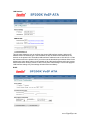
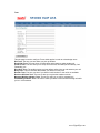
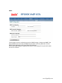
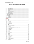
The web interface has two privilege levels: Administrator and User. Both privilege levels are
password protected by default. The user names for the Administrator and User are “admin” and
“user” respectively. And the default password for both privilege levels is “signalsys”. The major
difference between an Administrator and a User is Administrator has full control over the VoIP
device while User only has limited control. Here is a screen shot of the login prompt.
www.SignalSys.com
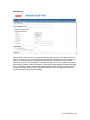
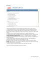
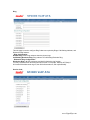
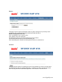
2.1 Home
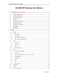
This page is the first page displayed when the device is logged in by an Administrator or a User.
As the screen shots shown above, user level privilege doesn’t have access to the configuration
page of SIP, CODECS, Download and Configuration. It shows how long the device has been
running since its last reboot, the IP address the device is currently using, whether or not the
device is password protected, and also displays the main application and downloader application
www.SignalSys.com
firmware versions. In addition, MAC address of the WAN port, and serial number of the device, if
it has one, are also displayed in this page.
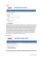
2.2 WAN
This page and its sub-pages are available on device that supports routing/bridging and allows
viewing and configuration of the WAN interface status/settings. Please note that any actions
/modifications which alter the topology of the Ethernet Bridge will result in the spanning tree
protocol to relearn. During this relearn period (may take up to one minute), HTTP access will be
unavailable on all bridged interfaces (including the LAN interface). Note that user level privilege
doesn’t have access to MAC Spoofing sub-page.
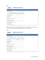
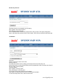
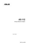
WAN Status
This page displays the current status of the WAN interface, including the IP address and other
network settings the interface is currently using. If the interface is configured for PPPoE, a button
is available to allow the administrator to DISCONNECT an active WAN PPPoE session or to
initiate (CONNECT) a PPPoE session (if currently disconnected).
www.SignalSys.com
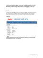
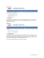
WAN Settings
This sub-page allows the user to configure the Ethernet WAN interface. First, select whether the
device is to act as a router or a bridge between the WAN and LAN interfaces. Select whether you
wish for the WAN interface to be configured dynamically (via a DHCP server on the network
if Ethernet, or via PPP if using PPPoE), or statically configured. If you wish to statically assign the
WAN interface settings, enter the IP address, subnet mask, default gateway IP address and DNS
server IP address. It is also recommended that the network domain name be provided as well, to
ensure correct DNS operation. Press "Save WAN Settings" to save and apply the new values.
Any new settings will take effect immediately.
www.SignalSys.com
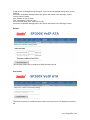
PPPoE
On this sub-page you can specify whether the WAN interface is to use PPPoE, and configure the
PPPoE client. First, select whether PPPoE is enabled or disabled. If enabled, enter the username
and password required for the login (authentication) process. Setting the idle-timeout will result in
the PPP connection being torn down if the client detects inactivity on the connection over the
specified timeout period. Leaving this field blank will result in the connection being permanently
up (i.e. without timeout). Setting the echo-timeout will result in the PPP connection to send the
echo request to server in specific time and the echo-count is used for disconnecting this PPP
connection if the device does not receive the response of echo request. If the PPPoE server
(service provider) requires any special Service Name or AC Name to be set, you can specify
these tags here. Press "Save PPPoE Settings" to save and apply the WAN interface PPPoE
client settings. Any new settings will take effect immediately.
MAC Spoofing
This sub-page allows the user to set the Ethernet hardware/MAC address to be used by the WAN
interface. This is typically done to mimic ('spoof' or 'clone') the MAC address of one of the devices
www.SignalSys.com
connected on the private LAN interface. Enter the MAC (12 hex digits) address to assign to the
WAN interface and press "Save MAC Spoofing Settings" to save and apply the new setting.
Note that only administrator level privilege has access to this sub-page.
2.3 LAN
This page allows configuration of the device's local network settings. Sub-pages are available for
the following on the left of page: the LAN interface status, configuration of the LAN interface
settings, and configuration of DHCP server settings, and Port Forwarding (NAPT) Settings.
LAN Status
This page displays the current status of the LAN interface, including the IP address and other
network settings the interface is currently using.
www.SignalSys.com
LAN Settings
This sub-page allows the user to configure the private LAN interface settings. Assign an IP
address to the LAN Ethernet port. This IP address is also the default router address for the
devices on the private LAN. The default LAN interface IP address is set to 192.168.123.1. Enter
the subnet mask for the private LAN. If you wish to set the broadcast and multicast limits for the
bridge/router, enter these values as percentages of the LAN interface Ethernet bit rate. Leaving
these values blank will imply values of 100%. Press "Save LAN Settings" to save and apply the
LAN interface settings. Any new settings will take effect immediately.
DHCP
www.SignalSys.com
This sub-page allows configuration of the private LAN DHCP server. The DHCP server settings
do not apply if the device is operating in bridge only mode. Specify whether the device's internal
DHCP server feature is enabled or disabled. Also indicate the IP address range to use for DHCP
assignments to the LAN. Specify the domain name (optional) that is provided to LAN clients via
DHCP. Two optional static DNS server IP addresses can be entered that will be provided to LAN
clients via DHCP. These are in addition to the DNS servers automatically provided by WAN
connections. Press "Save DHCP Settings" to save and apply the DHCP server settings. Any new
settings will take effect immediately. In addition, up to 8 static DHCP address assignments can be
configured. To add a static IP assignment, enter the LAN device's name (must be unique in the
private network) and/or MAC address. Specify the static IP to be assigned and press the "Add"
button. To remove an existing entry, press the "Remove" button next to the entry to be removed.
To view the current active DHCP client binding table (the internal list of devices for which the
server has provided an IP address lease), press "View DHCP Table". A popup window will
appear displaying the list of bindings. Press "Update" to update the binding information. Press
"Close" to close the binding table window. To clear the device's internal DHCP client binding
table, press "Clear client binding table". Be aware that doing this will destroy the DHCP server's
knowledge of the LAN clients it has provisioned, and may result in client problems when a client
tries to renew its lease.
Port Forwarding (NAPT)
This page allows the user to customize the devices port forwarding feature. The port forwarding
feature does not apply if the device is operating in bridge only mode. Port forwarding provides
WAN access to the internal LAN, by specifying that traffic over certain ports are to be directed at
particular LAN hosts. This feature is available only in router mode. Up to 8 ports forwarding
entries ("Pinholes") can be configured. To add a port forwarding entry, configure the Port Range
to be forwarded, the Protocol to be forward (TCP, UDP or both), and destination LAN IP Address,
press the "Add" button to add the entry. To remove an existing entry, click the "Remove" button
next to that entry you wish to remove. Note that certain port numbers are reserved by the CPE for
its own internal use. These ports may not be used for port forwarding to the LAN. Ports which
www.SignalSys.com
may be reserved by the device include those used by VoIP call signaling, RTP packets, HTTP
and SNMP. All reserved (unavailable) ports will be displayed on this page.
2.4 SIP Server
This page allows configuration of the SIP server and endpoint settings. Enter the address and
port value of the SIP server. The address may be an IP address or the name of the server. If no
SIP server address is entered, the device will attempt to self provision a SIP server using a DNS
query. For this to be successful, ensure that the DNS settings on the device include a DNS server
address that is configured with the SIP server address and will respond to the query, and the
appropriate domain name of the network. If you wish to specify a special SIP domain name, you
may enter the domain name here. If no domain name is entered, the SIP domain name will be set
to that of the network (i.e. that which is obtained via DHCP, or specified on the LAN settings
page). The currently provisioned SIP Server and Domain are displayed beside "SIP Server
Settings" for informational purposes. Select whether or not to send a Registration Request to the
SIP server by checking the box next to "Send Registration Request". For the endpoint, set the
dial plan to be used by all lines (refer to section 4.0 for details on the dialplan representation), and
select the transport method to be used for SIP signaling (either UDP or TCP). For each line on
the endpoint, enter the Line Phone Number, Caller-ID Name, signaling port value, authentication
Username and Password, and select if AEC is to be performed on this line. Press "Save SIP
Settings" to save the new values.
www.SignalSys.com
Extensions
This page allows specification of the SIP signaling stack behavior under certain scenarios.
1. Support PRACK method: If you wish for the SIP stack to implement reliable transmission of
provisional responses according to RFC 3262 (using the PRACK method) ,check the option.
2. Encode SIP URI with user parameter: include the user parameter “user=phone” in the SIP URI
headers.
3. Session Timer use UPDATE method: Session timer use update instead of reinvite.
4. Call Hold using C=0.0.0.0: using the call hold method described in RFC2543. If unchecked, the
call hold would follow RFC3263 method.
5. Enable Global Number support (E.164): add prefix "+" for dialed numbers in sip invitation.
6. Send NOTIFY for REFER request: send out NOTIFY request to transferor for unattended and
attended call transfer.
7. Send Message Waiting Indicator (MWI) SUBSCRIBE command: send SUBCRIBE after
registered to server to check if there are any messages to be read.
8. Send INVITE with Timer header: encode Timer header in all INVITE requests for ringing
timeout.
9. Enable SIP session timer: If you wish for the SIP stack to implement a session timer according
to “draft-sipsession-timer”, select the option.
10. SIP T1 Timer, SIP T2 Timer, and SIP T4 Timer: please refer to RFC3261.
Press "Save SIP Extension Settings" to save the new values.
www.SignalSys.com
User 1
This sub-page and the next User2 sub-page allow the user to configure the device with phone
number, caller ID, username and password specified by the service provider.
User 2
www.SignalSys.com
OOB Signaling
This sub-page allows configuration of the out-of-band signaling options for SIP. Select whether
OOB telephone event signaling is to be done using the SIP INFO message, or to be done via
RFC2833 RTP signaling.
ToS/DiffServ
This sub-page is used to configure the Type-of-Service/Diffserv byte values that are to be used in
the IP header of all transmitted SIP signaling packets and RTP packets. The ToS/DiffServ byte
values are entered as two-digit hexadecimal values. If no special ToS/DiffServ value is to be used
for a particular traffic type, enter "00" or leave the setting empty.
Press "Save ToS/DiffServ Settings" to save these new settings.
www.SignalSys.com
Tone
This sub-page is used to configure Tones which applies in order to acknowledge users.
Dial Tone: The tone you hear when you pick up handset
Recall Dial Tone: The tone when you hold callee and prepare to make another call.
Confirm Tone: The tone after you’ve set up some service, like DND (Do Not Disturb), Call
Forwarding, etc.
Ring Back Tone: The audible ringing you hear before callee picks up and answers your call.
Busy Tone: The tone indicates the number you dialed is in busy now.
Reorder Tone: The tone you hear if you dial an invalid number or the call is not available.
Receiver-Off-Hook Tone: The tone to alert you to place the handset on-hook.
Message-Waiting-Indicator Tone: The tone to notify you to call for message box.
Call-Waiting-Indicator Tone: The tone to make you aware of the second incoming call while
you’re in conversations.
www.SignalSys.com
Ring
This sub-page is used to configure Ring Cadences required by Rings, Call-Waiting-Indicator, and
Distinctive Ring features.
- Ring Configuration:
Default Ring: Default ring cadence when the phone rings.
Call-Waiting Reminder Ring: Ring cadence of Call-Waiting Reminder Ring.
- Distinctive Ring Configuration:
Distinctive Ring 1-8: Ring cadences provided for distinctive ring function.
You may customize them according the fixed format. For example, ON(500),OFF(500),R
Will cause 500 milliseconds ring on, then 500 milliseconds off, and repeat steadily.
Service Code
www.SignalSys.com
This sub-page is used to configure Service Code, you can subscribe for service by setting
through keypad.
Service Code Configuration:
Conditional Call Forwarding: 70#
Call Forward On: 72#
Call Forward Off: #72#
Do Not Disturb On: 74#
Do Not Disturb Off: #74#
Call Transfer: 98#
Call Return: 69#
Speed Dial: 68
Note: Do NOT change the service code values unless there is a conflict between the
settings of your VoIP device and the settings provided by your service provider.
2.5 CODECS
If the device is running one of the four VoIP applications, this page is available for configuring the
audio CODEC parameters, as well as the Jitter Buffer settings for the CODEC decoders.
Enter which CODECs are to be supported. For some protocols (e.g. H.323 and SIP), the G711U
and G711A protocols are always supported by default. For MGCP and H.248, it is possible to
remove these CODECs from the devices list of supported "capabilities". Select which complex
codec is to be supported. Due to memory limitations, it is not possible to select more than one
complex codec. Select the packetization period to be used for each selected CODEC. For MGCP,
a range of packetizations may be provided for each CODEC (to be advertised in the device's
"capabilities" set). Select whether Silence Suppression is to be supported for each CODEC.
The Jitter Buffer settings apply to all active CODEC decoders. You may choose between an
adaptive jitter buffer and a fixed jitter buffer. For an adaptive jitter buffer, choose the maximum
allowable playout delay (in milliseconds). For a fixed jitter buffer, choose the fixed playout delay
www.SignalSys.com
(in milliseconds). Finally, select whether or not a decoder should automatically switch from an
adaptive jitter buffer to a fixed jitter buffer upon fax/modem tone detection. Adaptive jitter buffers
are sometimes detrimental to fax transmission over G711 CODECs if they have to adapt too
rapidly or too extensively due to inconsistent and widespread packet delays. In these adverse
network conditions, a fixed jitter buffer provides superior performance when handling incoming
fax transmissions over G711 CODECs. Press "Save CODEC Settings" to save the new CODEC
parameters.
2.6 System Security
The password needed to access the VoIP device via web interface can be set in the sub-page.
First enter the old password, then enter the new password and confirm new password. Click on
the “Change Password” button to save the change. The VoIP device will log the user out and
redirect the user to the login page.
www.SignalSys.com
Set Security Timeout
This field will active, the password must be setting.
Click "System" item on the top menu.
Click "Security" on the left menu.
In HTTP Authentication Timeout field, input timeout value you want. Then press change time
button. After Http Authentication timeout value expired, it will redirect to password protected page.
Localization
Timezone:
Find the current time from a list of cities.
Country Caller ID:
The caller ID can find out who's calling you and keep track of how often they call.
Users should set the country field according to their geographical location, otherwise the Caller ID
function might not work properly.
Timezone setting:
Click "System" on the top menu.
Click "Localization" on the left menu.
In NTP Server field, enter a NTP server IP address.
If you want to use the default NTP server, this field should be blank.
In Time Zone drop down menu, select one time zone.
www.SignalSys.com
In Adjust clock for daylight savings checkbox, if your country has daylight savings time, you can
enable it.
Press Save Localization Settings button, then system will redirect to the web page of reset.
Country Caller ID setting:
Click "System" on the top menu.
Click "Localization" on the left menu.
In Country drop down menu, select one country.
Press Save Localization Settings button, then system will redirect to the web page of reset.
Handset
This sub-page allows user to configure the flash hook time interval.
Port Number
This allows the device to use different port number for the http server. The default port number is
80.
www.SignalSys.com
SNMP
This sub-page is used for configuring the device's SNMP manager. Configure the SNMP Trap
Host IP address and community, the SNMP read and write community parameters, and the
SNMP System Description and System Object ID parameters.
Press "Save SNMP Settings" to apply the new values. These settings will only take effect when
the device is rebooted.
www.SignalSys.com
Service Access
If the device is a multi-interface device (bridge/router), then this sub-page is available to
enable/disable access to certain system level network services on the device's interfaces. From
this page, an administrator can choose to allow or disallow HTTP, SNMP and Telnet access from
devices on the LAN or WAN or both. Care must be taken while configuring the HTTP access, as
once you have saved you will no longer be able to access the device's web pages if you have
disabled HTTP on the interface you are currently accessing the device on.
Press "Save Service Access Settings" to save and apply the new access settings.
2.7 Download
This page provides two options for downloading a new firmware application image to the device.
If you wish to download the new firmware image using TFTP, enter the filename of the ROM
image and enter the IP address of the TFTP server on which this file resides. To initiate the TFTP
download process, press "Start TFTP Download." If the ROM image is stored on the same local
machine you are using to access the device’s web pages, you can choose to download the ROM
file to the device using an HTTP post. Enter the filename of the ROM image or press "Browse" to
help locate the file. To initiate the HTTP download process, press "Start HTTP Download." If the
main application is executing at the time, the device will automatically reboot itself into the
downloader mode and begin the download process. If the downloader application is executing at
the time, the download process will begin. The download status will be displayed when the image
download process is complete.
www.SignalSys.com
Download
HTTP Download method:
When using http to upgrade firmware, it will check firmware version before starting download
process. In Filename field, press Browsing Button. Press Start HTTP Download button to start
downloading file. If firmware version doesn't fit in with old version, it won't allow updating.
2.8 Configuration Backup
Backup configuration values of system settings to a file from the device:
Click “Configuration” item on the top menu.
Click “Backup” item on the left menu.
Press Backup Configure File button to save configuration file.
www.SignalSys.com
Restore
This page is used to restore configuration values of system settings from a previously saved
configuration file, or default factory values that stored inside the device.
Restore configuration from a file:
Click “Configuration” item on the top menu.
Click “Restore” item on the left menu.
Press Browsing button to select file by backup from local machine.
Press Start Download button to process downloading file.
After downloading file is finished, the web system will redirect to restart device.
2.9 Reset
This page provides options for resetting the device. Select whether you wish to reset the device
and start executing the main (default) application, or whether you wish to reset the device and
start executing the internal downloader application. Press "Reset" to reset the device
www.SignalSys.com
2.10 Logout
This sub-page shows the user that s/he has log out from the device.
3.0 IVR
To use IVR, one should pick up the phone, and then dial four consecutive asterisks (****.) And
hang up the phone will stop IVR.
CODE STATUS USER INPUT
**** Menu Enter choice code.
100# Network status None.
110# DHCP setting
1# to enable
2# to disable
or # back to menu
120# IP address setting
Use “*” to instant of “.”, and “#” to end.
Ex: 172*16*230*227#
Or # back to menu.
130# Gateway setting Use “*” to instant of “.”, and “#” to end.
Or # back to menu.
140# Net mask setting Use “*” to instant of “.”, and “#” to end.
Or # back to menu.
4.0 DIAL PLANS
The SIP code will allow provisioning (via web browser) of the dial plan. A dial plan gives the unit a
map to determine when a complete number has been entered and should be passed to the SIP
server for resolution into an IP address. Dial plans are expressed using the same syntax as used
by MGCP NCS specification.
The formal syntax of the dial plan is described by the following notation:
Digit ::= "0" | "1" | "2" | "3" | "4" | "5" | "6" | "7" | "8" | "9"
Timer ::= "T" | "t"
Letter ::= Digit | Timer | "#" | "*" | "A" | "a" | "B" | "b" | "C" | "c"
| "D" | "d"
Range ::= "X" | "x" -- matches any digit
| "[" Letters "]" -- matches any of the specified letters
Letters::= Subrange | Subrange Letters
Subrange::= Letter -- matches the specified letter
| Digit "-" Digit -- matches any digit between first and last
Position::= Letter | Range
StringElement::= Position -- matches any occurrence of the position
| Position "." -- matches an arbitrary number of occurrences including 0
String ::= StringElement | StringElement String
StringList::= String | String "|" StringList
DialPlan::= String | "(" StringList ")"
A dial plan, according to this syntax, is defined either by a (case insensitive) string or by a list of
strings. Regardless of the above syntax a timer is only allowed if it appears in the last position in
a string (12T3 is not valid). Each string is an alternate numbering scheme. The unit will process
the dial plan by comparing the current dial string against the dial plan, if the result is underqualified (partial matches at least one entry) then it will do nothing further. If the result matches or
is over-qualified (no further digits could possibly produce a match) then send the string to the SIP
server and clear the dial string. The Timer T is activated when it is all that is required to produce a
match. The period of timer T is 4 seconds. For example a dial plan of (xxxT|xxxxx) will match
www.SignalSys.com
immediately if 5 digits are entered, it will also match after a 4 second pause when 3 digits are
entered.
4.1 Sample Dial Plans
Simple Dial Plan
This allows dialing of 7 digital numbers (e.g. 5551234) or an operator on 0. Dial plan is
(0T|xxxxxxx)
4.2 Non-Dialed Line Dial Plan
As soon as handset is lifted the unit contacts the SIP server (used for systems where DTMF
detection is done in-call). Dial plan is (x.) i.e. match against 0 (or more) digits. Note: the dot ‘.’
4.3 Complex Dial Plan
Local operator on 0, long distance operator on 00, four digit local extension number starting with
3,4 or 5, seven digit local numbers are prefixed by an 8, two digit star services (e.g. 69), ten digit
long distance prefixed by 91, and international numbers starting with 9011+variable number of
digits. Dial plan for this is:
(0T|00T|[3-5]xxx|8xxxxxxx|*xx|91xxxxxxxxxx|9011x.T)
General Troubleshooting
5.1 LED
LED “Power”: ON/OFF (indicates power connection)
LED “LAN”: ON/OFF (indicates LAN connection)
LED “WAN”: ON/OFF (indicates WAN connection)
LED “Status”: ON/OFF (indicate Registration status)
LED “Phone”: ON/OFF (indicates phone in use)
5.2 Mass Deployment
If the “Mass Deployment” is selected, the device will take approximate 20 seconds to startup.
The LED “Phone” is ON when the router is in “Mass Deployment”.
6. Make Phone Calls
6.1 Make a call
If you have your own dial plan, just dial the phone number. If you have no dial plan or using
default dial plan, dial the phone number. If the “# used as quick dial” is checked, you may dial the
phone number followed by #.
6.2 3-Way Conference
While two parties are in the conversation, either party can add the third party in the 3-way conference by
flash hook (hang up once while holding handset) and dial 7. After you hear a dial tone, please dial
telephone number to add third party for conference. To drop the third party, flash and dial 8.
6.3 Call Waiting
During the conversation, when you hear the call waiting tone, flash and dial “*”. It will switch you to the
incoming call. Flash and “*” again, it will be switched to the previous conversation.
6.4 Call Forwarding
Pick up the phone and dial *2. After hearing the dial tone, dial the forwarding phone number and #. Then,
hang-up the phone. The incoming calls will be forwarded.
To set call forwarding off, pick up the phone and dial *3.
www.SignalSys.com
APPENDIX
A. Determining the IP Address
This section provides instructions on how to determine the IP address of a unit, or how to boot up
into a ’safe’ mode that allows the IP address to be reconfigured. Instructions differ depending on
the platform type.
A.1 General Instructions
The following general instructions can be followed to determine the IP address of a unit.
Several mechanisms are available:
• If the device is thought to be using DHCP to obtain an IP address, check the DHCP
server log, leases file, or binding table (if available). Look for the MAC address of the
unit. The MAC address is a 6-octet string and can be found on a barcode label on the
device.
• Use a packet sniffer attached to the same network as the device. Set the sniffer to filter packets
based on the unit’s MAC address, and initiate some data packet transfer (e.g. make a VoIP call).
Analyze the captured packets to determine the device’s IP address.
• If the SNMP trap destination has been previously set, check your SNMP management server for
the IP address which is sent out as part of the Cold Start trap on system reset.
B. Forcing ’Safe’ Modes
The SP200X can be forced into a 'safe' downloader mode by performing the following steps in
order. In this description, the RESET button, which is the button at the back end of SP200X:
1. Power cycle the unit while holding down the RESET button. Release the RESET button in
less than 4 seconds.
2. To force the unit to use a fixed IP that is in the config file, press and immediately release the
RESET button again within 2 seconds of releasing it after step 1 above. After 2 seconds of button
inactivity, the device will start the downloader network stack in fixed IP mode. If no fixed IP
information exists in the configuration file, the device will default back to DHCP mode.
3. Finally, to force the unit to use 10.1.0.54 as the IP address, press and immediately release the
RESET button again a third time within 2 seconds of releasing it after step 3 above. The device
will now use 10.1.0.54 as the IP address.
REMINDER: There is a two second time-out after each press of the RESET button, after which
the downloader network stack will boot into the selected mode.
www.SignalSys.com
1 Presses = FIXED IP
2 Presses = 10.1.0.54
If the wrong network mode is started by mistake, the process can be easily restarted by holding
down the RESET button and power cycling the device again.
www.SignalSys.com