1
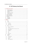
®
AX-112
Analog Telephone Adapter
User Guide
E2674/ June 2006
Copyright Information
E2674
First Edition
June 2006
Copyright © 2006 ASUSTeK COMPUTER INC. All Rights Reserved.
No part of this manual, including the products and software described in it, may
be reproduced, transmitted, transcribed, stored in a retrieval system, or translated
into any language in any form or by any means, except documentation kept by the
purchaser for backup purposes, without the express written permission of ASUSTeK
COMPUTER INC. (ASUS).
Product warranty or service will not be extended if: (1) the product is repaired,
modified or altered, unless such repair, modification of alteration is authorized in
writing by ASUS; or (2) the serial number of the product is defaced or missing.
ASUS provides this manual “as is” without warranty of any kind, either express
or implied, including but not limited to the implied warranties or conditions of
merchantability or fitness for a particular purpose. In no event shall ASUS, its
directors, officers, employees, or agents be liable for any indirect, special, incidental,
or consequential damages (including damages for loss of profits, loss of business,
loss of use or data, interruption of business and the like), even if ASUS has been
advised of the possibility of such damages arising from any defect or error in this
manual or product.
Specifications and information contained in this manual are furnished for
informational use only, and are subject to change at any time without notice,
and should not be construed as a commitment by ASUS. ASUS assumes no
responsibility or liability for any errors or inaccuracies that may appear in this
manual, including the products and software described in it.
Products and corporate names appearing in this manual may or may not be
registered trademarks or copyrights of their respective companies, and are used
only for identification or explanation and to the owners’ benefit, without intent to
infringe.
AX-112 Analog Telephone Adapter
Contact Information
ASUSTeK COMPUTER INC.
Company address:
General (tel):
Web site address:
General (fax):
General email:
15 Li-Te Road, Beitou, Taipei 11259
+886-2-2894-3447
www.asus.com.tw
+886-2-2894-7798
[email protected]
Technical support
General support (tel):+886-2-2894-3447
Online support:
http://support.asus.com
ASUS COMPUTER INTERNATIONAL (America)
Company address:
General (fax):
Web site address:
44370 Nobel Drive, Fremont, CA 94538, USA
+1-510-608-4555
usa.asus.com
Technical support
General support (tel):+1-502-995-0883
Online support:
http://support.asus.com
Notebook (tel):
+1-510-739-3777 x5110
Support (fax):
+1-502-933-8713
ASUS COMPUTER GmbH (Germany & Austria)
Company address:
General (tel):
Web site address:
General (fax):
Online contact:
Harkort Str. 25, D-40880 Ratingen, Germany
+49-2102-95990
www.asus.com.de
+49-2102-959911
www.asus.com.de/sales
Technical support
Component support: +49-2102-95990
Online support:
http://support.asus.com
Notebook support: +49-2102-959910
Support (fax):
+49-2102-959911
AX-112 Analog Telephone Adapter
Notices
Federal Communications Commission Statement
This device complies with Part 15 of the FCC Rules. Operation is subject
to the following two conditions:
• This device may not cause harmful interference, and
• This device must accept any interference received including
interference that may cause undesired operation.
This equipment has been tested and found to comply with the limits for
a Class B digital device, pursuant to Part 15 of the FCC Rules. These
limits are designed to provide reasonable protection against harmful
interference in a residential installation. This equipment generates, uses
and can radiate radio frequency energy and, if not installed and used
in accordance with manufacturer’s instructions, may cause harmful
interference to radio communications. However, there is no guarantee
that interference will not occur in a particular installation. If this equipment
does cause harmful interference to radio or television reception, which
can be determined by turning the equipment off and on, the user is
encouraged to try to correct the interference by one or more of the
following measures:
• Reorient or relocate the receiving antenna.
• Increase the separation between the equipment and receiver.
• Connect the equipment to an outlet on a circuit different from that
to which the receiver is connected.
• Consult the dealer or an experienced radio/TV technician for help.
Canadian Department of Communications Statement
This digital apparatus does not exceed the Class B limits for radio
noise emissions from digital apparatus set out in the Radio Interference
Regulations of the Canadian Department of Communications.
This class B digital apparatus complies with Canadian ICES-003.
AX-112 Analog Telephone Adapter
Conventions used in this guide
Symbols
To make sure that you perform certain tasks properly, take note of the
following symbols used throughout this manual.
DANGER/WARNING: Information to prevent injury to
yourself ��������������������������������
when trying to complete a task.
CAUTION: Information to prevent damage to the
components ������������������������������
when trying to complete a task
IMPORTANT: Instructions that you MUST follow to complete
a task.
�����
NOTE: Tips and additional information to help you complete
a task.
�����
AX-112 Analog Telephone Adapter
Table of Contents
1. Introduction...............................................................................7
Overview.................................................................................................7
Features . ...............................................................................................8
Hardware specifications . .......................................................................9
Package . ...............................................................................................9
2. Quick Installation....................................................................10
Connectors...........................................................................................10
Cable connection..................................................................................12
WAN IP assignment..............................................................................12
3. Configuration...........................................................................13
Status . .................................................................................................13
WAN ....................................................................................................13
SIP .....................................................................................................14
Advance setting ...................................................................................15
Management . ......................................................................................20
4. Operation.................................................................................22
IVR Operation ......................................................................................22
Call service features ............................................................................23
Life line/PSTN features . .....................................................................24
Conference/Transfer call .....................................................................24
LED indication . ....................................................................................24
5. Troubleshooting......................................................................25
AX-112 Analog Telephone Adapter
Chapter 1 - Introduction
English
1. Introduction
Overview
Thank you for buying an ASUS AX-112 Analog Telephone Adapter!
The ASUS AX-112 analog telephone adapter is a Session Initiation Protocol
(SIP) compliant Voice over Internet (VoIP) terminal adapter. It features high
audio quality, multiple telephone functions, and compact design. It can work
with SIP compliant devices and server to provide voice communication via the
Internet.
AX-112's compact design is specially-designed with WAN and LAN ports, and
with FXO and FXS ports. It supports Ethernet LAN to WAN bridge capability
and users can connect their PC or notebook to the Internet through the cable
on LAN port.
The FXO is designed with a bypass relay, which means that the FXO can pass
through connection to the phone set on FXS port. You can call via the internet
through:
• the phone set on FXS port; or
• pressing the control code on the phone key pad to switch to normal PSTN
line.
PSTN
NAT/Router
Internet
AX-112 Analog Telephone Adapter
Chapter 1 - Introduction
English
Features
•
•
•
•
•
•
•
•
•
•
•
•
•
•
Compact design for easy handling and installation
Supports SIP 2.0 (RFC3261), DHCP client, PPPoE, DNS, HTTP
Two RJ45 ports for WAN-LAN bridging
Two RJ11 jacks for one full function FXS port and one bypass FXO
port.
Supports most popular vocoders ; G.711u/A, G.723.1, G.729AB with 16ms
tail length line echo cancellation (G.168), silence suppression, VAD (Voice
Activity Detection), CNG (Comfortable Noise Generator)
Adaptive jitter buffer or user-configurable fixed jitter buffer length
Supports DTMF/FSK caller ID generation, and call transfer, call forwarding,
call waiting
DTMF operation mode: RFC2833, Info, in-band audio
Supports FAX pass through or T.38
Support standard encryption authentication, DIEGST with MD5
QoS Support 802.1Q VLAN, 802.1p, ToS, DiffServ
Supports Auto NAT traversal and STUN
Allows configuration by web browser or phone touch tone keypad
Firmware upgrade by TFTP or HTTP
AX-112 Analog Telephone Adapter
Chapter 1 - Introduction
Power
DC jack x 1
English
Hardware specifications
Power consumption <8W
Input voltage: 100-240 VAC
WAN port
RJ45, 10/100BaseT
Output voltage: 5VDC/2A
Auto MDI/MDIX
LAN port
RJ45, 10/100BaseT
Auto MDI/MDIX
FXS port
RJ-11 x1
On-hook voltage: 48VDC
Loop current: 25mA
FXO port
RJ-11 x1
LED
Red x 1, Green x 1
Dimension
9.8cm x 9.8cm x 2cm
Weight
100g
Ringer: REN 3, 55V/rms
No DAA function, with by pass relay only(life
line)
Green LED w/dimmer effect
Package contents
Check the following items in your ASUS AX-112 Analog Telephone Adapter
package:
AX-112 ATA x 1
RJ-45 Ethernet cable x 1, RJ11 phone cable x 1
5V/2A DC power adapter x 1
Quick Start Guide
AX-112 is able to operate SIP TA function by itself, and no other software
installation is needed. You may use IE to configure this device, or thru a
phone set plugged on the AX-112’s RJ11 jack. Please refer to Chapter 3
for configuration guide.
AX-112 Analog Telephone Adapter
Chapter 2 - Quick Installation
English
2. Quick Installation
2. 1 Connectors
There are five connectors on AX-112, and you can find them on the two
side panels. These two side panels can be distinguished by the arrow icon,
the upward arrow indicates the WAN side, while the other downward arrow
indicates the LAN side.
2.1.1 WAN side connectors
PWR
PWR
WAN
PSTN
(FXO)
WAN
DC power jack
Use the universal power adapter included in the package. The adapter is a
high quality switching power device which accepts 100~240VAC input, and
5VDC output with 2A rating. If you have to use a substitute power adapter,
use an adapter of good quality and with the correct rating. Incorrect voltage
adapter output may damage the AX-112, and poor quality adapter may induce
unacceptable ripple noise to the phone set.
RJ45 WAN
Normally, this port is connected to your broadband Ethernet port which could be
xDSL, cable modem or your office LAN. You have to assign an IP to the WAN port
of AX-112, or enable its DHCP client to get an IP from your DHCP server.
RJ11 line port
The line port is used for connecting to the PSTN line. It is also called as the Foreign
Exchange Office (FXO) port. This line port on AX-112 only has bypass function
without the DAA circuit. This means that it can relay the incoming call from PSTN
to the phone set connected to the phone port, but the VoIP call can not go through
by this line port.
10
AX-112 Analog Telephone Adapter
Chapter 2 - Quick Installation
English
2.1.2 LAN side connectors
LAN
LAN
PHONE (FXS)
LAN
Normally, you can only have one Ethernet cable at your desk. If you also have
to use your PC or notebook while the VoIP device is running, then an extra LAN
port is necessary for this purpose on AX-112. The LAN port has bridge capability
to WAN port and allows the connected device to be able to access the network
easily without other settings.
RJ11 phone port
AX-112 needs an ordinary phone set to work as an IP phone, and the RJ11
phone port is used for this purpose. Any ordinary analog phone set could be plug
into this jack. Then you may make the VoIP call, or switch the connection to the
PSTN (Public Switched Telephone Network) line and make a normal local phone
call. You can make the connection switch from the VoIP to the PSTN line through
pressing the special codes on the phone keypad. The default PSTN access code
is “*0” and it is user configurable.
Reset button
You may find the Reset button at the bottom of the case. Press the button, with a
small rod or pen, and hold for 5 seconds to restore the factory default settings.
Reset
AX-112 Analog Telephone Adapter
11
Chapter 2 - Quick Installation
English
2. 2 Hardware connection
• Use a standard Category 5 (CAT5) Ethernet cable with RJ45 jack to
connect the WAN port of AX-112 to the LAN port of your ADSL modem or
router.
• Use another Ethernet cable to connect your PC or notebook to the LAN
port of AX-112 if necessary.
• Use an ordinary phone cable with RJ11 jack to connect the phone-set to
AX-112’s phone port.
• Use another phone cable with RJ11 jack to connect the AX-112’s line port
to your PSTN jack if necessary. The PSTN jack is normally on the wall.
• Connect the power adapter, and then refer to the next section for how to
assign an IP address to the WAN port for future operation.
2. 3 WAN IP assignment
After you have correctly set up the hardware connection, the next step is
the WAN port IP assignment. You may assign a fixed IP address to AX-112
or enable its DHCP client to get an IP address from your DHCP server.
At the first stage of assigning an IP address to the WAN port, you may get the IP
address by using the phone-set and entering the proper DTMF code command.
AX-112 will the report the WAN address for you by voice. You may access the
WAN port’s IP address via IVR. Follow the instructions below:
1. Pick up the phone and dial “****”; and
2. After hearing the voice menu, dial “100#”. You should hear the WAN
status reported by voice.
By default, the AX-112’s WAN port is set to the DHCP client mode. If there is no
DHCP server in your network, you can assign a fixed IP address for AX-112 via
IVR. Refer to the Chapter 4 for more information on how to configure the IVR.
12
AX-112 Analog Telephone Adapter
Chapter 3 - Configuration
English
3. Configuration
In an Internet browser, enter the WAN IP address that you got either via the
DHCP server or the IVR). You will be taken to the AX-112’s web configuration
page, which consists of five menu items for future settings.
3. 1 Status
In this page, you will see all the system
status including WAN port status,
IP/MAC address, system uptime and
firmware version.
3. 2 WAN
You can either choose to statically
configure or to dynamically configure
the WAN interface (via a DHCP server
on the network, or via PPP if you are
using PPPoE),
If you wish to statically assign the WAN
interface settings: enter the IP address, the subnet mask, the default gateway
IP address, and the DNS server IP address. It is also recommended that the
network domain name be provided as well, to ensure correct DNS operation.
Press “Apply” to save and apply the new settings.
3.2.1 NTP server
To automatically obtain the time via the NTP server:
1.�������������������������������������������������������������������������������
Enter the NTP server address for the network (if this address is left blank, a
default public NTP server will be used, if accessible);
2. S���������������������
elect the time zone; and
���
3. Press the “Apply” button to save and apply the new settings.
AX-112 Analog Telephone Adapter
13
Chapter 3 - Configuration
English
3.2.2 MAC spoofing
This field allows the user to set the Ethernet hardware/MAC address to be used
by the WAN interface. This is typically done to mimic (‘spoof’ or ‘clone’) the MAC
address of one of the devices connected to the private LAN interface. To do this,
follow these steps:
1.�������������������������������������������������������������������������
Enter the 12 digits hardware address to assign to the WAN interface; and
2. Press the “Apply” button to save and apply the new settings.
3. 3 SIP
3.3.1 SIP proxy server
Enter the SIP server’s address and port
value. The address may either be an IP
address or the server’s name. If you wish
to specify a special SIP domain name,
you may enter the domain name here.
If no domain name is entered, the SIP
domain name will be set to that of the
network (i.e. that which is obtained via
DHCP, or specified on the LAN settings
page).
Select whether or not to send a Registration Request to the SIP server by
assigning a value (in seconds) for the “Registration Expiration”. Enter the line
phone number, the Caller-ID Name, the signaling port value, the authentication
username and the password.
There are two groups of SIP server IP and account data fields for user to enter,
AX-112 will try to register with the first one and if the first registration failed, it will
try the second SIP server IP, if you have entered the configuration data. If both
of the SIP servers IP failed to register, you will hear a busy tone when you pick
up the phone-set. Otherwise, you will hear a normal dialing tone if the registration
is successful.
3.3.2 Outbound proxy
If you need to use outbound proxy, assign the outbound proxy server IP and its
port number.
14
AX-112 Analog Telephone Adapter
Chapter 3 - Configuration
English
3.3.3 NAT traversal setting
Select the NAT traversal type. You may check the uPnP button if your NAT/Firewall
supports uPnP SIP ALG, or assign the STUN server IP if you are using STUN
service. You may also assign the RTP port if there is port enabling on your router
settings.
3.3.4 ToS/DiffServ settings
This sub-page is used to configure the Type-of-Service/Diffserv byte values. These
values are to be used in the IP header of all transmitted SIP signaling packets and
RTP packets. The ToS/DiffServ byte values are entered as a two-digit hexadecimal
value. If no special ToS/DiffServ value is to be used for a particular traffic type,
enter “00” or leave the setting empty.
3. 4 Advanced setting
There are five sub-pages in the advanced settings page. Basically, this page is for
the advanced users. Most of the time, the default settings should work for normal
application unless your service provider needs special configuration.
3.4.1 CODEC & Packet
CODEC configuration
Choose which codecs are to be supported. For SIP protocol, the G711U and
G711A protocols are always supported by default. You can select which complex
codec is to be supported in AX-112. But due to memory limitations, it is not possible
to select more than one complex codec at the same time.
You can also select to enable or disable the silent suppression function for each
codec type. To do this, just click on the checkbox beside a codec type.
AX-112 Analog Telephone Adapter
15
Chapter 3 - Configuration
English
Packetization period
Select the packetization period to be used for each selected CODEC. Each codec
has a different basic packetize period (usually it’s 30ms for G.723, 10ms for G.729).
You can select longer time period to increase the transmission efficiency. But,
longer packetization time will cause longer delay time.
3.4.2 DTMF & Gain & Dialling
DTMF
This field allows configuration of the
DTMF signaling options for SIP. Select
whether the OOB (Out-Of-Band)
telephone event signaling is to be done
using the SIP INFO message; or to be
done via RFC2833 RTP signaling; or
select in band audio which will directly
transmit out the DTMF tone.
Jitter buffer
The Jitter Buffer settings apply to all active CODEC decoders. You may choose
an adaptive jitter buffer or a fixed length jitter buffer. For an adaptive jitter buffer,
choose the maximum allowable play out delay (in milliseconds). For a fixed jitter
buffer, choose the fixed play out delay (in milliseconds). Finally, select whether
or not a decoder should automatically switch from an adaptive jitter buffer to
a fixed jitter buffer upon fax/modem tone detection. Adaptive jitter buffers are
sometimes detrimental to fax transmission over G711 CODECs if they have to
adapt too rapidly or too extensively due to inconsistent and widespread packet
delays. In these adverse network conditions, a fixed jitter buffer provides superior
performance when handling incoming fax transmissions over G711 CODECs.
Tx/Rx Gain
You can adjust the VoIP voice transmission and receive volume by adding or
decreasing the db value. The adjustable range is from –12db to +18db.
Actually , this is a very wide range for gain adjustment; the default value is 0 db
for both direction. To set the gain too high may cause echo, voice distortion or
DTMF tone will not be able to send the correct errors. Normally, it is reasonable
to make the adjustment between –6db to +6db range.
16
AX-112 Analog Telephone Adapter
Chapter 3 - Configuration
English
Phone default connect to
You can select the connection state of the phone set to VoIP FXS codec circuit
or to the PSTN port when the line is idle. It is set to ‘FXS’ by factory default for
normal usage. For one special case, when the caller ID signal from PSTN line
comes before the first ring, then you may select the phone set to be connected
to PSTN as default and ensure all the caller ID signal pass to the phone set.
When you select the option “Phone default connect to PSTN”, you must make
sure your PSTN line is properly connected to the RJ11 jack of the line port and it is
working properly. If your PSTN line is not working with proper voltage on line, the
phone set will not operate properly.
Dialing plan
A dialing plan gives the unit a map to determine when a complete number has
been entered. Dialing plans are expressed using the same syntax as used by
MGCP NCS specification. The formal syntax of the dialing plan is described by
the following notation:
Digit ::= “0” | “1” | “2” | “3” | “4” | “5” | “6” | “7” | “8” | “9”
Timer ::= “T” | “t”
Letter ::= Digit | Timer | “#” | “*” | “A” | “a” | “B” | “b” | “C” | “c”| “D” | “d”
Range ::= “X” | “x” --matches any digit | “[“ Letters “]” --matches any of the specified
letters
Letters::= Subrange | Subrange Letters
Subrange::= Letter --matches the specified letter | Digit “-” Digit --matches any digit
between first and last
Position::= Letter | Range
StringElement::= Position --matches any occurrence of the position | Position “.” -matches an arbitrary number of occurrences including 0
String ::= StringElement | StringElement String
StringList::= String | String “|” StringList
DialPlan::= String | “(“ StringList “)”
A dialing plan, according to this syntax, is defined either by a (case insensitive)
string or by a list of strings. Regardless of the above syntax a timer is only allowed
if it appears in the last position in a string (12T3 is not valid). Each string is an
alternate numbering scheme. The unit will process the dialing plan by comparing
the current dial string against the dialing plan, if the result is not qualified (partial
matches at least one entry) then it will do nothing further. If the result matches or
is over-qualified (no further digits could possibly produce a match) then sends
out the string and clear the dial string. The Timer T is activated when it is all that
is required to produce a match. The period of timer T is 4 seconds. For example
a dialing plan of (xxxT|xxxxx) will match immediately if 5 digits are entered, it will
also match after a 4 second pause when 3 digits are entered.
AX-112 Analog Telephone Adapter
17
Chapter 3 - Configuration
Simple dial plan
English
Allows dialing of 7 digit numbers (e.g. 5551234) or an operator on 0. Dial plan
is (0T|xxxxxxx) .
Complex dial plan
Local operator on 0, long distance operator on 00, four digit local extension number
starting with 3,4 or 5, seven digit local numbers are prefixed by an 8, two digit star
services (e.g. 69), ten digit long distance prefixed by 91, and international numbers
starting with 9011+variable number of digits. Dial plan for this is:
(0T|00T|[3-5]xxx|8xxxxxxx|*xx|91xxxxxxxxxx|9011x.T)
Quick dial key
This function lets you to select if you want to use the “#” or “*” key as end of
DTMF input key, it’s useful especially when the dialing number length is not
fixed. Pressing the “#” can notify AX-112 to stop waiting any more DTMF input
and sends the numbers out.
For system dialing plan, you may need to send the “#” and “*” key as part of the
dialing number. You may check the buttons to enable or disable this option.
Caller ID type
You can select the AX-112 output caller ID type to fit to different phone-set. AX112 can show the incoming call ID to your phone set LCD. There are four types
supported that you can choose from. Refer to the list below.
Bellcore(N.Amer,China)
ETSI FSK with Brief Ring
ETSI FSK With PR
NTT
(USA, CHINA , Belgium , Germany)
(France)
(UK)
(Japan)
Service code
This sub-page is used to configure the service code. After the service code
has been defined, you can subscribe to a call service by setting it through the
keypad. You must have defined the parameter of these fields before using
relative command by phone set. Click “Apply” to make save and apply the new
settings.
ASUS recommends that you change the service code values only if there is a
conflict with the setting of your service provider. Refer to Chapter 4: Operation
for more information.
18
AX-112 Analog Telephone Adapter
Chapter 3 - Configuration
Speed dial & phone book
English
AX-112 supports eight speed-dial and eight phone book entries for easy call
operation. You may enter the SIP extension number in the speed-dial fields. By
dialing the speed-dial prefix code (default is ‘*68n’) defined in the “Service Code”
with the speed dial index number (1~8), AX-112 will send out the call invitation
through the registered SIP server.
The phone book has almost the same function as the speed-dial. The difference
is, it needs a user ID, an IP address, and a port number to send out call invitation.
This means you can not send out call invitation to different IP addresses through
the registered SIP server. Click the “Apply” button to save and apply the new
settings.
Tone
The various tone patterns generated by the AX-112 are all configurable via the
standard configuration variable process. This section describes how to configure
the commonly used tones. The “language” for specifying the tone components is
quite simple. Basically, the language is a combination of frequency, duration and
amplitude and it is known as ABNF. Please refer to the following examples:
Example 1: European dialtone
425Hz @ -5dbm0, tone repeats indefinitely. In this case, the value of the ON time (i.e.
1000) is irrelevant, but MUST be greater than zero.
DIALTONE = 425@-5#ON(1000),R
Example 2: US ringback tone
440Hz @ -19dbm0 + 480Hz @ -19dbm0, with the following play out sequence being
repeated indefinitely: ON for 2s, OFF for 4s.
RINGBACK = 440@-19+480@-19#ON(2000),OFF(4000),R
Example 3: Custom tone with repeated states.
In this case, a tone of two frequencies (440Hz@-5dbm0 + 1200Hz@-5dbm0) is played
out according to the following timing sequence: ON for 500ms, OFF for 500ms, ON for
500ms, OFF for 500ms, ON for 500ms, OFF for 500ms, ON indefinitely (the value of
the last ON is irrelevant, but must be non-zero).
CUSTOM_1 = 440@-5+1200@-5#[ON(500),OFF(500)]3,ON(1000),R
AX-112 Analog Telephone Adapter
19
Chapter 3 - Configuration
English
3. 5 Management
3.5.1 Administration password
In the old password field, input the
old password, if you have it. In the
new password field, input the new
password. In the confirm password
field, input the password again for
confirmation. Click the “Apply” button
to save the changes. If you have set
the password, the system will redirect
to the password-protected web
page. Input password that you have
changed , then press “Authenticate”
button into the system.
3.5.2 Firmware upgrade
This page provides three options
for downloading a new firmware
application image to the device.
If you wish to download the new
firmware image using TFTP, enter
the filename of the ROM image and
enter the IP address of the TFTP
server on which this file resides.
Press “Start” to initiate the TFTP
download process. If the ROM image is stored on the same local machine you
are using to access the device’s web pages, you can choose to download the
ROM file to the device using an HTTP post or URL. Enter the filename of the
ROM image or press “Browse” to help locate the file. Press “Start” to initiate the
HTTP download process.
20
AX-112 Analog Telephone Adapter
Chapter 3 - Configuration
English
3.5.3 Configuration
To backup all the setting value in a file on your PC, just click the backup “Start”
button and then enter the file name to keep the data. To retrieve the setting value
from a file, click the restore “Start” button and enter the file name of the file you
want to retrieve.
3.5.4 Restore factory default
To restore AX-112’s factory default settings, click the “Start” button. You can also
press the reset button, located at the bottom of the case, for 5 seconds.
If you have made any changes to the configuration, reboot the AX-112 adapter.
AX-112 Analog Telephone Adapter
21
Chapter 4 - Operation
English
4. Operation
4. 1 IVR operation
To use the IVR, pick up the phone and dial four consecutive asterisks (****) to
enter the main IVR menu. To stop the IVR, just hang up the phone.
****
CODE
Menu
STATUS
USER INPUT
Enter choice code.
100#
Network status
None.
110#
WAN setting
1# to enable DHCP mode
2# to enable Static IP mode
3# to enable PPPoE mode
22
120#
IP address setting
# back to menu
Use “*” to instead of “.”, and “#” to
end. Or # back to menu.
130#
Gateway setting
Same as IP address setting
140#
Net mask setting
Same as IP address setting
AX-112 Analog Telephone Adapter
Chapter 4 - Operation
English
4.2 Call service features
AX-112 has a set of pre-defined service dial code for using the functions such
as conditional forwarding, call return, and PSTN mode switch. Refer to the
table for the functions’ description and usage.
FUNCTION
Conditional Call Forwarding
PRESS
KEY
(Default)
*70#
USAGE
Call Forward On
*72#
Enter the forwarding phone number right
after *70#, you will hear 3 short tone as
confirm.
Same as above
Call Forward Off
#72#
3 short tone will be played as confirm
Do Not Disturb On
*74#
Do Not Disturb Off
#74#
Same as above. Will reject all incoming
call.
3 short tone will be played as confirm
Call Transfer
*98#
Enter the destination phone number
right after *98#, and hang up phone after
hearing 3 short tone will transfer the call
(blind transfer).
Call Return
*69#
Auto redial the previous one missed
incoming call.
Speed Dial
*68n
There are 8 speed dial number entries
on web GUI, you have to predefine
the phone number in each field for
this function. The value ‘n’ indicates
the relative number of speed dial field
number from 1 to 8.
The relative setting fields on the web can not be left blank. You have to predefine
all the call service command in the web GUI in advance, or use the default setting,
before using service functions.
ASUS recommends that you change the service code values only if you have meet
conflict with the setting of your service provider.
AX-112 Analog Telephone Adapter
23
Chapter 4 - Operation
4.3 Life line / PSTN access
English
By default, when you pick up the phone set and dial a number, the number is
interpreted as a VoIP call. If you have connected the FXO to PSTN line on AX112, you can dial to the PSTN line instead of VoIP by the PSTN access code. The
PSTN’s default access code is “*0”, and it is user configurable on the web GUI.
4.4 Conference call / Transfer call
To transfer a call
Blind Transfer: Transferring a call to a thri party without notifying the recipient.
Dial “*98#nnnn” (nnnn is the phone number of recipient) and hang up.
Attendant Transfer: Transferring a call to recipient an ensuring the call is
successfully transferred.
Talking with A --> Press ‘Flash’ key -->(Dial tone present) --> Dial the new party
number of B -->Press “*98#” --> Transfer complete
To make 3-way conference call
Talking with A --> Press ‘Flash’ key -->(Dial tone present) --> Dial the new party
number of B --> Conference
4. 5 LED indication
There are two LEDs located on the center and inside the box, they are in red and
green color. There is no LED hole or lens to guide the light out of the plastic box,
instead, the light is directly penetrating out of the white upper case. Refer to the
table for the possible status of the LED lighting pattern.
LED Pattern
Red LED always on
Red LED blinking
Possible Status
Firmware upgrading
SIP server registration fail/IP not
defined
System error
Green LED always on
SIP server registration success
Green LED blinking
SIP server registration processing
Green LED on and off gradually every Call progression
two seconds
24
AX-112 Analog Telephone Adapter
Chapter 5 - Troubleshooting
English
5. Troubleshooting
5.1 General Troubleshooting
There is no LED activity at power on.
•Check that the power supply unit (PSU) is properly connected.
•Check if the ‘Phone default connect to’ option at ‘Advanced’ setting page. If it
were set to “PSTN’ and your PSTN line is not wired properly (without voltage
presented), then there will be no dialing tone at all. If you have no PSTN line
connected to the AX-112 line port, please set the ‘Phone default connect to’
option to “FXS”.
5.2 Network Troubleshooting
General network activity problems. The device does not appear to be
performing any network related functions.
•For Ethernet devices, make sure that the Ethernet connection is secure, and
the Ethernet cable quality is good.
• Try pinging the device’s IP address from any Unix or Windows machine
connected to the same network.
Input: ping www.xxx.yyy.zzz [Enter]
(where www.xxx.yyy.zzz is the IP address of the unit).
The automatic DNS discovery process for a VoIP server does not
appear to work.
•Ensure that the DNS server is capable of servicing DNS TXT or SRV
queries, and that it is configured to respond with the correct server
information when queried.
• If the device is configured via DHCP, ensure that the DHCP server has provided
the correct DNS server and the domain name information.
AX-112 Analog Telephone Adapter
25
Chapter 5 - Troubleshooting
The device’s Web pages are not accessible.
English
• Try pinging the device’s IP address.
• The unit is trying to acquire a DHCP IP address. Make sure that the Ethernet
cable connection is secure.
• Verify that the DHCP server on the network is functioning.
•If you do not have a DHCP server or want to use a fixed IP address instead,
you need to reconfigure the device to use a static network assignment.
•If the device network information has been statically assigned (i.e. not via
DHCP), ensure that the DNS server IP address is correct, and that the network
domain name has been provided and is correct.
The web browser complains often about errors on the page.
• Ensure that the web browser supports frames and that javascript is enabled.
Although the device’s internal web pages should be accessible from most
modern web browsers, we recommend using Microsoft IE 5.0 (or later version)
or Netscape4.0 (or later version) for optimal results.
The interface is configured for PPPoE, but is not working.
• If authentication is required, check that the username and password are
correct.
• The PPPoE server may require special Service Name or AC Name tags.
Check with the server if these tags are required and make sure the appropriate
values are configured.
I’ve forgotten the IP address of the device, and hence cannot reach it via my
web browser
•Please refer to Chapter 4.1 IVR Operation for how to use IVR to check your
WAN port status.
26
AX-112 Analog Telephone Adapter