1
co
m
ji.
er
en
eo
w
w
w
.n
FRONIUS IG 300 / 400 / 500
42,0410,1288
012006
GB Operating instructions
Inverter for mains-connected
photovoltaic systems
ji.
er
en
eo
.n
w
w
w
co
m
Dear Reader
Introduction
Thank you for choosing Fronius - and congratulations on your new, technically highgrade Fronius product! This instruction manual will help you get to know your new
machine. Read the manual carefully and you will soon be familiar with all the many
great features of your new Fronius product. This really is the best way to get the most
out of all the advantages that your machine has to offer.
w
w
w
.n
eo
en
er
ji.
co
m
Please also take special note of the safety rules - and observe them! In this way, you
will help to ensure more safety at your product location. And of course, if you treat your
product carefully, this definitely helps to prolong its enduring quality and reliability - things
which are both essential prerequisites for getting outstanding results.
ud_fr_st_et_00493
012004
ji.
er
en
eo
.n
w
w
w
co
m
Safety rules
DANGER!
co
m
“DANGER!” indicates an imminently hazardous situation which, if not
avoided, will result in death or serious injury. This signal word must be
limited to the most extreme situations. This signal word is not used for
hazards relating to property damage unless there is also a risk of personal
injury appropriate to this level.
WARNING!
ji.
“WARNING!” indicates a potentially hazardous situation which, if not
avoided, could result in death or serious injury. This signal word is not used
for hazards relating to property damage unless there is also a risk of personal injury appropriate to this level.
CAUTION!
en
er
“CAUTION!” indicates a potentially hazardous situation which, if not avoided, may result in minor or moderate injury. It may also be used to draw
attention to unsafe practices that may cause damage to property.
“NOTE!” indicates a situation which implies a risk of impaired results and
damage to the equipment.
eo
NOTE!
Important!
“Important!” indicates practical hints and other particularly useful information. It is not a signal word for a harmful or dangerous situation.
w
.n
Whenever you see any of the symbols shown above, pay close attention to
the contents of the manual!
w
w
General Remarks
This equipment has been manufactured in accordance with the state of the
art and general safety-engineering principles. Nevertheless, incorrect operation or misuse may still endanger
- the life and well-being of the operator or of third parties,
- the equipment and other tangible assets belonging to the owner/operator,
- working efficiently with the equipment.
All persons involved in any way with starting up, servicing and maintaining
the equipment must
- be suitably qualified
- have good knowledge of dealing with electrical installations and
- read this instruction manual thoroughly and follow the instructions to the
letter.
The instruction manual must be kept at the machine location at all times. In
addition to the instruction manual, it is important to comply with both the
generally applicable and local accident prevention and environmental protection regulations.
I
ud_fr_se_sv_00923
022005
General Remarks
(continued)
All the safety instructions and warning signs on the machine itself:
- must be kept in a legible condition
- must not be damaged
- must not be removed
- must not be covered, pasted or painted over
For information about where the safety instructions and warning signs are
located on the machine, please refer to the section of your machine’s instruction manual headed “General Remarks”.
Any malfunctions which might impair machine safety must be remedied
immediately before the machine is switched on.
Utilisation for
Intended Purpose
Only
co
m
Your safety is at stake!
The machine may only be used for jobs as defined by the “intended purpose”.
ji.
Utilisation for any other purpose, or in any other manner, shall be deemed
"not in accordance with the intended purpose". The manufacturer shall not
be liable for any damage resulting from such improper use.
en
er
Utilisation in accordance with the “intended purpose” also comprises
- thorough reading of and compliance with all the instructions, safety
instructions and warnings given in this manual
- performing all stipulated inspection and servicing work
- installation in accordance with the instruction manual
eo
Where appropriate, the following guidelines should also be applied:
- regulations of the power supply company for input to the grid
- information provided by the manufacturer of the solar modules
Operation or storage of the machine outside the stipulated range is deemed
“not in accordance with the intended use”. The manufacturer shall not be
liable for any damage resulting therefrom.
w
w
.n
Ambient
Conditions
w
Qualified Staff
Please refer to the technical data in your instruction manual for accurate
information about the permissible ambient conditions.
The servicing information provided in this instruction manual is only intended
for qualified staff. An electric shock can be fatal. Please do not carry out any
activities other than those referred to in the documentation. This also applies
even if you are suitably qualified.
All cables and other leads must be firmly attached, undamaged, properly
insulated and adequately dimensioned. Have loose connections, scorched,
damaged or under-dimensioned cables and wires repaired immediately by
an authorised specialist company.
ud_fr_se_sv_00923
022005
II
Qualified Staff
(continued)
Maintenance and repair may only be carried out by an authorised specialist
company.
There is no guarantee in the case of parts sourced from other suppliers that
these parts have been designed and manufactured to cope with the stresses
and safety requirements that will be placed on them. Use only original spare
parts (this also applies to standard parts).
Do not carry out any alterations, installations or modifications to the machine
without first getting the manufacturer’s permission.
co
m
Replace immediately any components that are not in perfect condition.
Safety Precautions at the Machine Location
Ensure when installing machines with cooling-air vents that the cooling air can flow freely
through the air vents without obstruction. Only operate the machine with the degree of
protection specified on the rating plate.
Care must be taken during installation to ensure that there is no occurrence
of electromagnetic interference with electrical and electronic equipment.
Electrical Installations
Electrical installations may only be executed in accordance with the relevant
national and regional standards and specifications.
eo
en
er
ji.
EMC Precautions
Danger of damage to electronic components due to electrostatic discharge.
Take appropriate protective measures when replacing and installing the
components.
w
.n
ESD Protective
Measures
w
w
Safety Precautions in Normal
Operation
Only operate the machine if all its protective features are fully functional. If
any of the protective features are not fully functional, there is a danger to:
- the life and well-being of the operator or other persons
- the equipment and other tangible assets belonging to the owner/operator
- working efficiently with the equipment.
Have any safety features that are not fully functional repaired by an authorised specialist company before switching the machine on again.
Never bypass or disable safety features.
III
ud_fr_se_sv_00923
022005
Equipment with the CE mark fulfils the basic requirements of the Guideline
Governing Low-Voltage and Electromagnetic Compatibility. (More detailed
information about this may be found in the Annex or in the section of your
documentation headed “Technical Data”.)
Disposal
Do not dispose of this device with normal domestic waste!
To comply with the European Directive 2002/96/EC on Waste Electrical and
Electronic Equipment and its implementation as national law, electrical
equipment that has reached the end of its life must be collected separately
and returned to an approved recycling facility Any device that you no longer
require must be returned to our agent, or find out about the approved collection and recycling facilities in your area.
Ignoring this European Directive may have potentially adverse affects on the
environment and your health!
Data security
The user is responsible for backing up data relating to changes made to
factory settings. The manufacturer will not accept liability if personal settings
are deleted.
Copyright
Copyright to this instruction manual remains the property of the
manufacturer.
en
er
ji.
co
m
Safety markings
w
w
w
.n
eo
The text and illustrations are all technically correct at the time of going to
print. The right to make modifications is reserved. The contents of the
instruction manual shall not provide the basis for any claims whatever on the
part of the purchaser. We should be most grateful for your comments if you
have any suggestions for improvement, or can point out to us any mistakes
which you may have found in the manual.
ud_fr_se_sv_00923
022005
IV
Contents
Protection of personnel .................................................................................................................................
Safety .......................................................................................................................................................
Housing unit .............................................................................................................................................
Galvanic (electrical) isolation ...................................................................................................................
Monitoring the mains network ..................................................................................................................
Mains connection .....................................................................................................................................
Photovoltaic generator .............................................................................................................................
3
3
3
3
3
4
4
co
m
Safety strategy .............................................................................................................................................. 5
Standards and regulations ....................................................................................................................... 5
Declaration of conformity ......................................................................................................................... 5
How a photovoltaic system works .................................................................................................................
General ....................................................................................................................................................
Current is generated on the roof ..............................................................................................................
Current is converted underneath the roof ................................................................................................
6
6
6
7
er
ji.
The FRONIUS IG in the photovoltaic system ................................................................................................ 8
General .................................................................................................................................................... 8
Converting DC to AC current .................................................................................................................... 8
Fully automatic operational management ................................................................................................ 8
Voltage transformation and galvanic isolation .......................................................................................... 8
Monitoring the mains network .................................................................................................................. 9
Display function and data communication ................................................................................................ 9
Plus points: ............................................................................................................................................. 10
eo
en
The FRONIUS IG ......................................................................................................................................... 11
Mode of operation ................................................................................................................................... 11
MIX system ............................................................................................................................................. 11
Startup phase ......................................................................................................................................... 12
FRONIUS IG 500 overview .................................................................................................................... 13
LED for operating status ........................................................................................................................ 14
Status LEDs on the power modules ....................................................................................................... 14
15
15
15
15
Navigating around the display .....................................................................................................................
Display illumination ................................................................................................................................
Menu level ..............................................................................................................................................
Choosing a display mode .......................................................................................................................
17
17
17
17
The display modes ......................................................................................................................................
Scrolling between display functions .......................................................................................................
Overview of display modes ....................................................................................................................
Overview of display values .....................................................................................................................
„Day“ / „Year“ / „Total“ display mode .......................................................................................................
18
18
18
18
24
The Setup Menu ..........................................................................................................................................
Overview of the menu items ...................................................................................................................
„Setup“ display mode .............................................................................................................................
Open the setup menu .............................................................................................................................
Move up and down the menu items .......................................................................................................
Setting the menu items ..........................................................................................................................
27
27
27
28
28
29
w
w
w
.n
The display ..................................................................................................................................................
General ..................................................................................................................................................
Description of the keys ...........................................................................................................................
Symbols .................................................................................................................................................
Supplementary information ......................................................................................................................... 39
Add-on system components ................................................................................................................... 39
String control system .............................................................................................................................. 39
1
Installation instructions ................................................................................................................................ 41
Opening the housing ................................................................................................................................... 42
FRONIUS IG .......................................................................................................................................... 42
Replacing the cylinder lock .................................................................................................................... 42
Installation ...................................................................................................................................................
Transporting by crane ............................................................................................................................
Selecting a location ................................................................................................................................
Fitting the base .......................................................................................................................................
IP 20 version: Fitting the exhaust pipe ...................................................................................................
IP 43 version: Fitting the hood and exhaust pipe ...................................................................................
Forced-air ventilation ..............................................................................................................................
42
42
42
43
44
44
45
co
m
Cleaning the air filter ................................................................................................................................... 46
General information ............................................................................................................................... 46
Cleaning the air filter .............................................................................................................................. 46
er
ji.
Connecting the solar modules and the mains .............................................................................................
Solar modules ........................................................................................................................................
Monitoring the mains network ................................................................................................................
Installations with several inverters ..........................................................................................................
Strain relief .............................................................................................................................................
AC leads and a pair of DC leads ............................................................................................................
AC leads and a two pairs of DC leads ....................................................................................................
External power supply to rack ................................................................................................................
Fasten strain-relief device ......................................................................................................................
External contactor control (if required by your power supply company) .................................................
47
47
47
47
48
48
48
49
49
49
en
Configuring the inverter ............................................................................................................................... 50
Factory configuration .............................................................................................................................. 50
Custom configuration ............................................................................................................................. 50
eo
LocalNet ......................................................................................................................................................
Add-on system components/plug-in card system ..................................................................................
Datalogger ..............................................................................................................................................
COM card ...............................................................................................................................................
Installing plug-in cards ...........................................................................................................................
Configuration ..........................................................................................................................................
Example .................................................................................................................................................
51
51
51
51
51
52
53
.n
Replacing fuses ........................................................................................................................................... 54
Replacing fuses ..................................................................................................................................... 54
w
w
w
Service codes displayed ..............................................................................................................................
Service display .......................................................................................................................................
General service codes ...........................................................................................................................
Total failure .............................................................................................................................................
Status diagnosis for power modules ......................................................................................................
Class 1 ...................................................................................................................................................
Class 2 ...................................................................................................................................................
Class 3 ...................................................................................................................................................
Class 4 ...................................................................................................................................................
Class 5 ...................................................................................................................................................
Customer service ...................................................................................................................................
55
55
55
55
56
57
58
59
60
62
64
Technical data ............................................................................................................................................. 65
FRONIUS IG 300 / 400 / 500 ................................................................................................................. 65
Standards and directives with which the equipment complies ............................................................... 66
Warranty and liability ...................................................................................................................................
Warranty requirements and liability ........................................................................................................
Scope of warranty ..................................................................................................................................
Warranty period ......................................................................................................................................
Proof for warranty purposes ...................................................................................................................
67
67
67
68
68
Disposal ...................................................................................................................................................... 68
Recycling ................................................................................................................................................ 68
2
Protection of personnel
Safety
co
m
WARNING! If the equipment is used or tasks are carried out incorrectly,
serious injury or damage may result. The tasks required to commission and
maintain your FRONIUS IG system must only be carried out by a trained
engineer, and in accordance with the technical regulations. It is essential that
you read the „Safety Regulations“ chapter before commissioning the equipment or carrying out maintenance work.
Housing unit
The connection area must be opened only by an authorised installation engineer.
Never open the connection area when the power is connected.
ji.
The power supply unit’s enclosure must only be opened by a trained FRONIUS service
technician, and only when the power is disconnected.
Galvanic (electrical) isolation
er
The FRONIUS IG is constructed and operated in the safest possible way, both in terms
of installation and operation. The DC and AC sides are completely galvanically (electrically) isolated from one another to ensure optimum levels of safety.
eo
en
The FRONIUS IG is used for galvanic isolation and for monitoring the mains network.
These functions include the passive and active measures for protecting both people and
equipment.
In the event of abnormal conditions in the mains network (e.g. mains disconnection or
interruption), the FRONIUS IG will immediately stop working and will cease feeding
current into the mains network.
.n
Monitoring the
mains network
The FRONIUS IG offers a number of facilities for monitoring the mains:
Voltage monitoring
Frequency monitoring
Over/undervoltage relay (optional)
w
w
w
This is a safe way of preventing dangerous voltages from developing on the AC leads
and is an important contribution to minimising dangers for maintenance engineers.
3
Photovoltaic
generator
Before you connect up the solar panels you should check that the voltage specified by
the manufacturer corresponds to the actual measured voltage.
When you measure the voltage, you should bear in mind that when the temperature is
low and the insolation is constant, the open-circuit voltage generated will be higher.
If the outside temperature is -10°C, the open-circuit voltage for the solar panels should
never rise above 530 V. The relevant temperature coefficients for calculating the theoretical open-circuit voltage at -10°C can be found in the data sheet for the solar panels.
co
m
If the open-circuit voltage for the solar panels rises above 530 V, this will result in complete destruction of the FRONIUS IG and all warranty rights shall be declared null and
void.
Only an authorised electrical engineer is permitted to connect this equipment to the
public mains network.
w
w
w
.n
eo
en
er
ji.
Mains connection
4
Safety strategy
Standards and
regulations
„WARNING! Risk of fatal injury from electrical voltage from the solar modules. In Italy, due to the country-specific ENEL DK5940 Directive in force, the
following inverter in the FRONIUS IG 400 and IG 500 series must be connected to the public grid using the operator’s own isolating transformer. The
transformer is supplied with a user manual (operating instructions), which
must be consulted when installing the device.“
co
m
Your FRONIUS IG meets all the relevant standards and regulations.
The most important of these are:
-
.n
Relevant declarations of conformity can be found in the appendix to these operating
instructions.
w
w
w
Declaration of
conformity
eo
-
ji.
-
er
-
Directive 89/336/EEC on Electromagnetic Compatibility
Directive 93/68/EEC on CE marking
General EMC standards
EN 61000-6-2, EN 61000-6-4
General safety standard
EN 50178
Overvoltage protection standard
EN 61000-4-5
Standard for flicker measurements
EN 61000-3-11, EN 61000-3-12
“Guidelines for the parallel operation of in-plant photovoltaic generation systems
with the low voltage grid of the electricity supply companies” published by the
German Electricity Industry Association (VDEW)
“Technical directives for the parallel operation of in-plant photovoltaic generation
systems with the low voltage grid of the electricity supply utilities” published by the
Austrian Electricity Plants Association
en
-
5
How a photovoltaic system works
The amount of solar energy radiated worldwide amounts to approx.
1,540,000,000,000,000,000 kWh per year (1,540 peta kWh / year). This is 15,000 times
more than the total electricity consumed. We would like to congratulate you on your
decision to make active use of the world’s largest energy pool. Incidentally, the photovoltaic effect was originally discovered in 1839 by the French physicist Alexandre-Edmond
Bequerel. The term ‘photovoltaic’ comes from the driving force behind this technology,
the light beam. The light beam consists of unimaginably small particles called photons.
Current is generated on the roof
For simplicity, our starting point will be an explanation of a pure silicon solar cell. If we
think back to our physics lessons at school we might recall that in its outer electron
sheath, silicon has four electrons around its atomic nucleus. These four electrons are
known as the ‘valency electrons’. The photons, i.e. the sunlight, penetrate the solar cells
and strengthen the valency electrons by adding energy. The electron finally detaches
itself from the silicon atom, leaving behind a positively-charged atom.
ji.
co
m
General
er
To ensure that the detached electrons all flow in the same direction to form a current, the
front and rear sides of the cell must have opposite polarities.
en
The silicon atoms on the front side are displaced by a small number of phosphorus
atoms with their extra valency electron. On the rear side of the cell, on the other hand, in
addition to the silicon atoms, boron atoms (which have only three valency electrons) are
also built up.
eo
The resulting imbalance between the positive and negative poles causes the electrons to
flow, thus producing an electrical current.
w
w
w
.n
When a number of these solar cells are packed together behind a pane of glass, they
form one of your solar modules.
6
Current is generated on the roof
(continued)
The efficiency and the voltage are increased by connecting solar modules together.
If solar modules are connected in series to
form a string, both the potential power and
the voltage are increased.
Voltage
module 1
+
Voltage
module 2
Mod.n
Total string voltage
Mod.2
Voltage
module 3
String
Mod.1
-
String 3
Mod.2
Mod.n
er
-
co
m
String 2
Mod.1
When a number of these strings are
connected in parallel, both the potential
power and the module current are increased while the voltage remains the same.
All the solar modules that are connected in
parallel and in series are described collectively as a ‘solar generator’.
ji.
String 1
+
Total string voltage = voltage
module 1, 2, ... n
Fig. 1 Solar modules connected in series
en
Fig. 2 Solar modules connected in parallel
The DC current generated in the solar modules cannot be fed into the public mains
network or used within the household unless it has first been converted in the inverter.
This is the primary function of the FRONIUS IG.
w
w
w
.n
eo
Current is converted underneath the roof
7
The FRONIUS IG in the photovoltaic system
Your FRONIUS IG is a state-of-the-art photovoltaic inverter. It acts as a highly sophisticated link between the solar modules and the public mains network.
General
As such, it is responsible for a number of important functions.
The FRONIUS IG converts the direct current (DC) generated by the solar modules into
alternating current (AC). This alternating current is fed synchronously into the mains
supply in your in-house network and the public mains network. The FRONIUS IG has
been developed specifically for use in photovoltaic systems that are linked to the mains.
Power cannot be generated independently from the public mains network.
Fully automatic
operational
management
The FRONIUS IG operates fully automatically. As soon after sunrise as the solar modules are producing sufficient power, the control module starts monitoring the mains
voltage and frequency. When insolation has reached a sufficient level your photovoltaic
inverter will start to feed current. Depending on the model, just a few watts of solar
energy can be sufficient for this purpose!
er
ji.
co
m
Converting DC to
AC current
en
The FRONIUS IG consistently works in a way that ensures the maximum power possible
is obtained from the solar modules.
.n
The FRONIUS IG is designed for use with solar modules with a wide range of voltage
input. This enables the widest possible variety of types of solar module to be used.
However, it is of the utmost importance to ensure that the stated values for maximum
DC voltage (the total voltage of the solar cells connected) are never exceeded.
w
Voltage transformation and
galvanic isolation
eo
This function is known as MPPT (maximum power point tracking), and is implemented
with maximum precision. As soon after dusk as the power available has fallen below the
level at which current can be fed into the mains, the FRONIUS IG disconnects itself
completely from the mains and stops running. Needless to say, it retains all its settings
and stored data.
w
w
The FRONIUS IG is constructed and operated in the safest possible way, in terms of
assembly and installation as well as operation.
8
Voltage transformation and
galvanic isolation
(continued)
The FRONIUS IG is equipped with an HF transformer (HF = high-frequency) which
ensures that the DC side is galvanically isolated from the mains network. Furthermore,
the HF design enables the transformer to be significantly smaller, which means space and more importantly weight - requirements are considerably reduced. Despite the fact
that FRONIUS IG implements complete galvanic isolation, its innovatively designed
circuitry enables it to achieve a high degree of efficiency.
Monitoring the
mains network
The FRONIUS IG is responsible for monitoring the mains. This responsibility includes
implementing measures to protect operators and equipment alike in the event of a mains
failure.
co
m
The FRONIUS IG is programmed to stop working immediately and to cease feeding
current into the mains network in the event of abnormal conditions in the mains network
(e.g. mains disconnection or interruption).
ji.
The FRONIUS IG has a number of different ways of detecting a mains disconnection:
Voltage monitoring
Frequency monitoring
Over/under-voltage relay (optional)
en
er
In this context it is important to note that the specific monitoring procedures applicable in
the country concerned are implemented by the FRONIUS IG itself, and do not involve
any additional electronic measuring equipment. This significantly reduces the time
required for installation and the associated costs.
The complexity of the technology in this new generation of photovoltaic inverters means
that a good deal of thought needs to go into the design of the display, which is, in effect,
the user interface. The display design is uncompromisingly oriented towards simple
operation and to making the system data available at all times.
eo
Display function
and data communication
.n
The FRONIUS IG already has a basic function for logging minimum and maximum
values on a daily and total basis; this is done directly at the display. The display also
provides the option of displaying the following weather data:
2 different temperature values (e.g. temperature at the solar modules, outside
temperature in the shade)
Insolation
w
w
w
In addition to the functions implemented in the FRONIUS IG, the wide range of data
communication elements enables a multitude of different data logging and display
options. The add-on system components required for this purpose are easy to install
(see operating instructions for FRONIUS IG DatCom). When add-on system components such as DatCom components are installed, functions such as remote system
monitoring via a modem, sending an SMS message to a mobile in the event of a malfunction, data display and comparison on a PC all become possible.
9
Plus points:
The more functions (described above) the inverter handles, the more simple and efficient the installation will be since there will be no need for extra peripherals. Because of
our experience and thanks to the state-of-the-art technology we have built in, the FRONIUS IG can manage all these tasks simultaneously.
The FRONIUS IG also meets a large number of the criteria for the protection of people,
other domestic equipment as well as itself.
These criteria include:
Monitoring the mains network
The quality of the current fed into the mains
Sensitivity to interference (e.g. from mobile phones)
w
w
w
.n
eo
en
er
ji.
co
m
The relevant certificates can be found in the appendix.
10
The FRONIUS IG
The FRONIUS IG is designed for fully automatic operation. Basically, no manual operation is needed in order to feed power into the mains.
Mode of operation
The FRONIUS IG starts automatically as soon after sunrise as the solar modules are
delivering sufficient power. From this time onwards, system data will be displayed on the
FRONIUS IG graphic display.
co
m
Whilst the FRONIUS IG is running it keeps the voltage of the solar modules constantly
within the range for obtaining maximum power.
The optimum voltage for the operational status of the solar modules at any given
time is known as the MPP voltage (MPP = maximum power point).
Sticking strictly to the MPP voltage at all times ensures that the solar modules
always operate as efficiently as possible (MPP tracking).
er
ji.
As soon after dusk as the power available to feed into the mains falls below a sufficient
level, FRONIUS IG disconnects completely from the mains.
FRONIUS IG does not take any power out of the public mains network overnight.
Stored data and settings are retained.
The system can also be switched off manually.
The MIX concept ensures that the power modules are comprehensively managed.
Instead of one large power module, there are several small power modules to convert
the current. When the insolation level is low, not all the power modules in the inverter will
be switched on. As a result, the power modules operate in a higher partial-load range
than would be the case with a single large power module. This enables the energy to be
converted much more efficiently. The other power modules switch on only as the output
increases.
eo
en
MIX system
w
w
w
.n
The name „Master Inverter X-Change (MIX)“ more or less explains how the device
works: One power module (the master) is responsible for coordination, and controls the
deployment of the other power modules. The control software assigns the master role to
the different power modules in turn. This work-sharing method reduces the number of
operating hours for individual power modules and improves results in partial-load situations.
Another advantage of the MIX system is that it is relatively failsafe. If one power module
fails, the others simply take on the work it was doing. This means that power losses will
only occur when the insolation level is high, and even then they will be limited.
In summary, the MIX system offers the following benefits:
Optimum efficiency by switching off unnecessary power modules
Power modules are used equally thanks to the intelligent management system
The system is failsafe as it consists of a large number of independent power modules
11
Once the FRONIUS IG has been switched on automatically it carries out a self-test
routine. After this, the public mains network is tested.
Startup phase
This test can take from just a few seconds up to several minutes depending on national
regulations. During start-up the LED will appear yellow.
(1) Segment test
All the display elements will be illuminated for approximately one second
co
m
(2) TEST
Self-test of the FRONIUS IG’s main components
The FRONIUS IG takes just a few seconds to run through a virtual checklist
The display will show “TEST” as well as the component currently being tested
(e.g. “LED”)
er
ji.
(3) Synchronisation with the mains
The display shows „WAITPS“: FRONIUS IG waits for all the power modules on
the mains to be ready. This procedure is dependent on the DC voltage.
Next, the display will show „SYNCAC“
en
-
.n
eo
(4) Startup test
Before the FRONIUS IG feeds power into the mains network for the first time,
the mains conditions are tested thoroughly in accordance with the relevant
national regulations.
“STARTUP” will appear on the display
Two of the previously flashing dividing marks disappear for every 10% of the total duration of the startup test that has been completed.
w
w
w
The startup test can take anything from just a few seconds up to several minutes depending on national regulations. Progress is indicated by a vertical bar which reduces in
size from top to bottom.
12
Startup phase
(continued)
(5) Feeding power into the mains
Once the tests have been completed the FRONIUS IG starts feeding power into
the mains
The LED is illuminated green and the FRONIUS IG is in operation
co
m
(6) Checking the roof fans
When power is starting to be fed into the mains, the fan controller is checked. This
involves the roof fans running for approx. 20 seconds.
FRONIUS IG 500
overview
ji.
WARNING! Risk of fatal injury from electrical voltage from the solar modules.
Before removing power modules or their covers:
Disconnect FRONIUS IG on both the AC and DC side
Wait 10 minutes to allow capacitors to discharge
For safety reasons, make sure that the lowermost power module is
inserted correctly in the FRONIUS IG.
er
(1) Connection area
(2) Power modules
(5)
(2)
(6) Display with key unit
(6)
w
w
w
(2)
(1)
(4) Optional modules, including fan
controller and display with LED for
operating status
(5) Module containing four roof fans
.n
(4)
eo
(3)
en
(3) Status LEDs on the power modules
(3)
13
The LED will change colour depending on the operating status
LED for operating status
(1) LED steady green:
Comes on after the FRONIUS IG’s automatic start-up phase and stays on as long
as power is being fed into the mains
The photovoltaic system is working correctly
(2) LED flashing green:
The photovoltaic system is working correctly
A message also appears on the display
co
m
NOTE! A message will appear if, for instance, there is an insulation fault even if
it does not have any adverse effect on the FRONIUS IG’s operation. However,
our advice is that, for safety reasons, the insulation fault is rectified as soon as
possible.
A status message is displayed. If a message such as “502”! is displayed (see chapter
entitled “Status diagnosis and repair”), the status concerned should be rectified and the
“Enter” key then pressed in confirmation.
ji.
(3) LED steady orange:
The FRONIUS IG will enter its automatic startup phase as soon after sunrise as the
photovoltaic modules are delivering sufficient power
en
er
(4) LED flashing orange:
A warning appears on the display
Or the FRONIUS IG has been switched to standby mode in the setup menu = power
feed-in is switched off manually
Power feed-in is resumed automatically after the next sunrise
When the orange LED is flashing, power feed-in can be started manually at any time
(see chapter entitled “The Setup Menu”)
eo
(5) LED steady red:
General status: The relevant service code is shown on the display
.n
A list of service codes, corresponding status messages, and causes and remedies for
particular statuses can be found in the chapter entitled “Status diagnosis and repair” in
the installation and service instructions.
w
w
(6) LED remains dark:
No connection to solar modules
No output from module due to absence of daylight
w
Status LEDs on
the power modules
(1) LED flashing green:
The power module is in the startup phase
(2) LED steady green:
The power module is in feed-in mode
(3) LED remains dark:
No slave is required due to the low level of insolation
14
The display
The FRONIUS IG is pre-configured and ready to use. There is no need to make any
initial settings before using it to feed power into the mains, which is a fully-automated
process.
General
The display unit’s power is supplied by the solar modules, which means that the display
unit can be used in the daytime.
co
m
Important! The FRONIUS IG’s display is not a calibrated measuring instrument. A slight
inaccuracy of a few percent is intrinsic to the system. A calibrated meter will be needed
to make calculations for the power supply company.
Description of
the keys
Key (A) and (B)
For scrolling
(B)
(C)
“Enter” key (D):
For confirming a choice
(D)
en
(A)
er
ji.
Key (C):
For switching to the menu level
(“Menu”) or exiting the setup menu
(“Esc”)
Symbols
(12)
(11)
w
w
w
(10)
(9)
(7)
(8)
.n
(5)
eo
(2)
(6)
(4)
(1)
(3)
(1) Symbols for keys (A) to (D)
(2) Symbols for display modes „Now“ to „Setup“
(3) Range for display value ... for displaying the value
(4) Range for display unit ... for displaying the associated unit
(5) Segment column ... always shows the amount of power being fed into the mains in
real time - irrespective of the display mode selected. Displayed as a percentage of
the maximum power that your photovoltaic inverter is capable of feeding in.
15
Symbols
(continued)
(6)
... appears when values are displayed which are directly associated with the public
mains network
(7)
... appears when values are displayed which are directly associated with the solar
module
(8)
... appears when values are displayed which are directly associated with the FRONIUS IG
(9)
... appears when values are displayed which are associated with environmental
conditions such as insolation and temperature (optional)
co
m
(10) ... appears when values are displayed which have been transmitted by the (optional) consumption sensor
(11) Max ... The value shown represents the maximum period of time in question (depending on which display mode is selected).
(12) Min ... The value shown represents the minimum period of time in question (depending on which display mode is selected).
w
w
w
.n
eo
en
er
ji.
Important! The minimum and maximum values displayed do not represent the absolute
extreme values because data is only recorded at 2-second intervals.
16
Navigating around the display
Press any key to light up the display. If no key is pressed for 30 seconds or more, the
display illumination will go off again. The setup menu also offers a choice between
display lighting permanently on or permanently off.
Display illumination
You can access the display mode you
want, or the setup menu, from the menu
level.
co
m
Menu level
Press key (C) to switch to the menu level
ji.
(C)
-
„Menu“ will appear on the display
The display is at menu level
-
Switching to menu level
Use keys (A) or (B) to choose your
preferred display mode (1) to (4)
Entering the chosen display mode:
Press „Enter“ key (D)
eo
en
er
(C)
Choosing a
display mode
(2)
(3)
(4)
.n
(1)
w
w
-
w
(A)
(A)
(B)
(D)
(B)
(D)
17
NOTE! The “Year” menu option is
supported only when the optional
datalogger is connected. This
add-on system component
includes a real-time clock.
Scrolling
between display
functions
(A)
(B)
(A)
-
(B)
co
m
(A)
(B)
Choose your preferred display mode (see above)
Use keys (A) and (B) to scroll between the available display functions
er
ji.
The display modes
The following display modes are available:
Overview of
display modes
en
„Now“ display mode ... Displays real-time values
„Day“ display mode ... Displays values for power fed into the mains during that day
eo
„Year“ display mode ... Displays values for power fed into the mains during the current
calendar year - only in conjunction with an optional datalogger
Overview of
display values
.n
„Total“ display mode ... Displays values for power fed into the mains since the FRONIUS IG was originally commissioned.
The table below provides an overview of the display values available.
*
Optional - If the necessary option card is not present, then the letters „N.C.“ are
displayed (not connected)
w
w
w
Those display values listed without a footnote will be displayed in a „standard“ setup
(factory setting).
18
Overview of
display values
(continued)
„Day“ / „Year“ / „Total“ display mode
„Now“ display mode
Energy fed into the mains
(kWh / MWh)
Mains voltage 1)
(V)
Return
(Currency can be selected)
Current fed into the mains 1)
(A)
CO2 reduction
(kg / t)
Mains frequency
(Hz)
Maximum power fed into the mains
(W)
Module voltage 2)
(V)
Maximum mains voltage
(V)
Module current
(A)
Minimum mains voltage
(V)
co
m
Power fed into the mains
(W)
* Module temperature
(°C; or alternatively °F)
Maximum module voltage
(V)
* Recorded by the consumption meter
Energy (kWh / MWh)
eo
* Time
(HH:MM)
* Minimum module temperature
(°C; or alternatively °F)
en
* Ambient temperature
(°C; or alternatively °F)
* Insolation
(W/m²)
* Maximum ambient temperature
(°C; or alternatively °F)
* Minimum ambient temperature
(°C; or alternatively °F)
* Maximum insolation
(W/m²)
.n
Service hours completed by the
FRONIUS IG
(HH:MM)
Value displayed is applicable to the mains phase of the master power module. Use
the „Enter“ key to call up the submenu for the other mains phases (L1, L2, L3).
w
w
1)
* Maximum module temperature
(°C; or alternatively °F)
er
* Recorded by the consumption meter
Power (W)
ji.
Insulation resistance
(MOhm)
w
Value for phase 1 (L1)
=
Value for phase 2 (L2)
Value for phase 3 (L3)
~
Return to main menu
2)
Displayed value applies to the master power module.
19
Overview of
display values
(continued)
Display of real-time values
-
Select „Now“ display mode (see chapter entitled „The Display“)
The first display function of the “Now” display mode will appear
*
Optional - If the necessary option card is not present, then the letters “N.C.” are
displayed.
(A)
(B)
You can access the next value by
pressing key (B)
Use key (A) to scroll back
Mains voltage (volts) ... from the
master power module phase ...
Measured value applies to the threephase mains circuit
(Example: 231 V * 1.73 = 400 V)
eo
en
er
ji.
~
co
m
Power fed in ... Power (in watts)
currently being fed into the mains
Mains frequency
(hertz)
.n
Module voltage ... Voltage (in volts)
currently present at the solar modules
w
w
w
Current fed in ... Current (in amperes) currently being fed into the
mains ... from the master power
module phase
The voltage displayed whilst power is being fed into the mains corresponds to what is
known as MPP voltage (MPP = maximum power point). The FRONIUS IG always
maintains the module voltage within the range that allows the maximum possible power
to be obtained from the solar modules. This ensures that your photovoltaic system is
always operating at maximum efficiency.
20
Overview of
display values
(continued)
Module current ... Current that is
being supplied at present by the solar
modules ... (amperes)
The FRONIUS IG always maintains the module voltage within the range that allows the
maximum possible power to be obtained from the solar modules. This results in the
optimum module current.
Module temperature ... Temperature
at the solar modules (°C; can be
changed to °F in the setup menu;
temperature sensor no. 1; sensor card
option)
co
m
*
ji.
Insulation resistance of the photovoltaic system (MOhms)
er
The insulation resistance is the resistance between the positive or negative poles in the
photovoltaic system and the earth potential. If an insulation resistance > 500 kOhms is
shown, this means that the photovoltaic system is adequately insulated.
en
WARNING! An insulation resistance of < 500 kOhm may be due to an inadequately insulated DC lead or defective solar modules. In the event that the
insulation resistance is too low, it is essential that you consult your FRONIUS
service agent.
eo
Important! Only an insulation resistance of less than 500 kOhms indicates a fault. If the
insulation resistance displayed is greater than this, it can be assumed that there is no
such fault.
.n
In the case of an insulation resistance of less that 10 MOhms, the display differentiates
between the negative potential and earth (polarity sign „-“) and the positive potential and
earth (polarity sign +“).
w
w
Example of display for negative potential
(polarity sign „-“)
Short circuit between DC lead and
earth
w
Example of display for positive potential
(polarity sign „+“):
Short circuit between DC+ lead and
earth
*
21
Power taken out of the mains ...
Current consumption (in watts; optional sensor card)
*
Ambient temperature (°C; °C; can
be changed to °F in the setup menu;
temperature sensor no. 2; sensor
card option)
*
Insolation ... Insolation power coming
down on each square metre (watts/
m²; optional sensor card)
*
Time (optional datalogger) ... if the
time is changed on a FRONIUS IG or
an add-on system component, it will
also be changed in any other devices
that are connected via LocalNet.
co
m
Overview of
display values
(continued)
Example of display for positive potential
(polarity sign „+“):
Short circuit between DC+ lead and
earth
*
Power taken out of the mains ...
Current consumption (in watts;
optional sensor card)
*
Ambient temperature (°C; °C; can
be changed to °F in the setup menu;
temperature sensor no. 2; sensor
card option)
*
Insolation ... Insolation power coming
down on each square metre (watts/
m²; optional sensor card)
w
w
w
.n
eo
en
er
ji.
Example of display for negative potential
(polarity sign „-“)
Short circuit between DC lead and
earth
22
Overview of
display values
(continued)
=
~
=
~
Fan controller malfunction
Fan controller ready for operation
co
m
Inlet air temperature (°C)
The roof fan speed and the code for the
fan concerned are displayed alternately.
RPM = revolutions per minute
FL = “front left”
FR = “front right”
BL = “back left”
BR = “back right”
en
er
ji.
=
~
BL
BR
FL
FR
=
~
Figure 3 - Code for roof fan
w
w
w
.n
eo
=
~
=
~
23
Overview of
display values
(continued)
*
„Day“ / „Year“ /
„Total“ display
mode
Time (optional datalogger) ... if the
time is changed on a FRONIUS IG or
an add-on system component, it will
also be changed in any other devices
that are connected via LocalNet.
„Day“ display mode ... Displays values for power fed into the mains during that day
Return (currency can be selected)
CO2 reduction (kg)
Maximum power fed into the mains (watts)
Maximum mains voltage (volts)
Minimum mains voltage (volts)
Energy taken out of the mains (kWh)
Service hours completed by the FRONIUS IG
er
ji.
-
co
m
Important! Switch-on time represents the beginning of the working day for the FRONIUS IG. If the DC-in lead is disconnected, the following values will be reset after the unit
has been restarted.
en
The above instruction does not apply if an optional datalogger is being used. If the
optional datalogger is available, the totalled display values apply in any case to the whole
day of feeding power into the mains.
eo
„Year“ display mode ... Displays values for power fed into the mains during the current
calendar year - only in conjunction with a data logger
.n
„Total“ display mode ... Displays values for power fed into the mains since the FRONIUS
IG was originally commissioned.
Select „Day“ / „Year“ / „Total“ display mode (see chapter entitled „The Display“)
The first display function of the selected display mode will appear
*
Optional - If the necessary sensor card is not present, the letters “N.C.” are displayed.
w
w
-
w
Energy fed in ... Energy fed into the
mains over the period of time in
question (kWh / MWh)
(A)
(B)
There may be discrepancies with values displayed on other measuring instruments
because of differences in methods of measurement. As far as adding up the energy fed
in is concerned, the only binding display values are those produced by the calibrated
measuring device provided by the electricity supply company.
-
You can access the next value by pressing key (B)
Use key (A) to scroll back
24
„Day“ / „Year“ /
„Total“ display
mode
(continued)
Return ... amount of money earned
during the period of time in question
(currency can be selected in the Setup
menu)
Important! As with energy fed in, here too there may be discrepancies with other
measured values.
The chapter entitled „Setup Menu“ describes how to select a currency and charge rate.
The factory setting is 0.48 Euro per kWh.
co
m
CO2 reduction ... CO2 emissions
saved over the period of time concerned
(kg/t)
ji.
Amount of CO2 (in kg/t), which would be emitted in the production of the same amount of
current in a caloric power plant. The factory setting is 0.53 kg / kWh (source: DGS - the
German Society for Solar Energy).
en
er
Maximum power fed in ... largest
amount of power (W) fed into the
mains over the period of time in
question
Maximum mains voltage ... largest
mains voltage (V) measured during
the time in question ... from the
master power module phase ...
Measured value applies to the threephase mains circuit
(Example: 231 V * 1.73 = 400 V)
Max
Minimum mains voltage ... smallest
mains voltage (V) measured during
the time in question ... from the
master power module phase ...
Measured value applies to the threephase mains circuit
(Example: 220 V * 1.73 = 380 V)
Min
w
w
.n
eo
~
w
Maximum module voltage ... highest
module voltage (V) measured during
the time in question
*
25
Energy recorded by the consumption meter ... energy consumed during
the time in question (kWh / MWh;
optional consumption sensor)
*
Maximum module temperature ...
highest temperature measured at the
solar modules during the time in
question (°C; can be changed to °F in
the setup menu; temperature sensor
no. 1; sensor card option)
*
Module temperature ... lowest
temperature measured at the solar
modules during the time in question
(°C; can be changed to °F in the setup
menu; temperature sensor no. 1;
sensor card option)
*
Maximum ambient temperature ...
highest temperature measured during
the time in question (°C; can be
changed to °F in the setup menu;
temperature sensor no. 2; sensor
card option)
ji.
NOTE! The temperature sensor
should be mounted on the rear
side of the solar modules.
co
m
„Day“ / „Year“ /
„Total“ display
mode
(continued)
Minimum ambient temperature ...
lowest temperature measured during
the time in question (°C; can be
changed to °F in the setup menu;
temperature sensor no. 2; sensor
card option)
eo
en
er
*
*
Maximum insolation ... highest level
of insolation during the time in question,
(W/m²; optional sensor card)
w
.n
Service hours ... Number of service
hours completed by the FRONIUS IG
(HH:MM)
Although the FRONIUS IG does not operate during the night, the data required by the
optional sensor card is logged and stored 24 hours a day.
w
w
The service hours are shown in hours and minutes up to 999 hours and 59 minutes
(„999:59“). After that, only the hours are shown.
26
The Setup Menu
Overview of the
menu items
The brief overview shows the menu items for changing the FRONIUS IG’s initial settings.
Standby
Enter
Contrast
0 ... 7
AUTO
Cash
ON
Currency
IG no.
OFF
co
m
LightMode
Charge rate / kWh
DatCom
Time
Date
SIGCD_TEST
Time
en
State_FAN
Error
er
OKCom
ji.
01 ... 99
(100. FRONIUS IG = 00)
Fan status display
State_PS
eo
Status display for power modules
w
„Setup“ display
mode
MainCtrl
PS00 .... PS14
Fan Control
.n
Version
w
w
The setup menu allows the FRONIUS IG’s initial settings to be changed easily to bring it
in line,as closely as possible, with your preferences and requirements.
27
Open the setup
menu
(1)
(2)
(3)
(4)
-
(5)
-
Move to the menu level (see chapter
entitled „Navigating around the
display“)
Use keys (A) or (B) to choose „Setup“
mode (5)
Enter „Setup“ mode (5): Press „Enter“
key (D)
(A)
(A)
(B)
(D)
-
The first menu item, „Standby“, is
shown.
er
ji.
(D)
co
m
(B)
eo
en
Move up and
down the menu
items
(B)
-
(A)
(A)
(B)
(B)
Choose your preferred display mode (see above)
Use keys (A) or (B) to move between the available menu items
w
w
w
.n
(A)
28
Setting the menu
items
-
„Standby“ ... Use the „Enter“ key (D)
to switch on / switch off standby
mode.
(D)
The „Standby“ menu item provides the facility to put the FRONIUS IG into standby mode
manually.
The power electronics are switched off in standby mode. No power is fed into the mains.
The LED flashes orange.
co
m
The following messages appear alternately on the display:
-
LED steady green: Switch on „Standby“ = manually switch off power feed into mains:
Press „Enter“ key (D)
LED flashing orange: Switch off “Standby” = resume feeding power into mains
Press “Enter” key (D)
w
w
w
.n
-
en
-
The orange flashing LED goes off after dusk
After sunrise the following day the feeding of power into the mains is resumed
automatically (LED will show steady green after the startup phase)
While the LED is flashing orange, the feeding of power into the mains can be
resumed at any time (switch off „Standby“ mode)
eo
-
er
ji.
„STANDBY“ „ENTER“
29
(C)
(D)
„Contrast“ ... Adjusts contrast on the
LCD display.
-
To initiate contrast adjustment: Press
„Enter“ key (D)
Since the contrast is temperature-dependent, when the ambient conditions change
it may be necessary to adjust the contrast.
(D)
Choose a setting from „0“ to „7“
- press key (A) or (B):
co
m
-
-
Settings Minimum contrast (0) to maximum contrast (7):
accept: Press „Enter“ key (D)
restore previous setting: Press “Esc”
key (C)
(C)
(A)
(D)
ji.
...
en
(D)
.n
eo
(C)
er
(B)
w
w
w
(C)
30
-
„Menu mode“ ... cannot be selected
(C)
-
„Light mode“ ... Initial setting for
display illumination.
-
To initiate „light mode“ adjustment:
Press „Enter“ key (D)
1.
The display illumination is switched off
if no keypress is detected for 30
seconds
Accept: Press „Enter“ key (D)
Restore previous setting: Press „Esc“
key (C)
(D)
To change between the settings
Auto 1., On 2. and Off 3. - press
key (A) or (B):
(C)
(D)
ji.
(A)
co
m
(D)
-
(B)
The display illumination remains
permanently switched on while power
is being fed into the mains
Accept: Press „Enter“ key (D)
Restore previous setting: Press „Esc“
key (C)
(C)
(A)
.n
(C)
-
(D)
eo
(B)
en
er
2.
3.
-
The display illumination is permanently switched off:
Accept: Press „Enter“ key (D)
Restore previous setting: Press „Esc“
key (C)
(D)
w
w
w
Important! This setting relates only to the display’s background illumination There is no
need to switch off the display itself as it uses only a small amount of energy (less than
one mW (1/1000 W)).
(C)
(D)
(D)
1
2
31
-
„Cash“ ... Sets the currency and
charge rate for the energy fed into the
mains
-
To initiate „Cash“ adjustment: Press
„Enter“ key (D)
1
2
(A)
(D)
(B)
(C)
1.
Enter currency (factory setting: EUR)
-
First digit flashing
Use key (A) or (B) to select a letter for
the first character
Press „Enter“ key (D) to confirm
Next digit flashing
-
(D)
...
(A)
(B)
(C)
(D)
ji.
(D)
The procedure for entering the other
digits is the same as for the first digit
(described above)
Accept currency: Press „Enter“ key
(D)
Restore previous setting: Press „Esc“
key (C)
co
m
...
-
er
2.Enter charge rate per kWh in the chosen
currency (factory setting: 0.48 EUR/kWh)
(A)
(D)
(B)
(C)
(D)
-
First digit flashing
Use key (A) or (B) to select a number
for the first digit
Press “Enter” key (D) to confirm
Next digit flashing
The procedure for entering the other
digits is the same as for the first digit
(described above)
w
.n
eo
...
...
en
-
(A)
(B)
(C)
(D)
w
(D)
w
(A)
(B)
(C)
(D)
Important! The range for this value is
from 000.1 to 99.00.
32
Decimal point flashing
Use key (A) or (B) to move the decimal point to the right position
Accept the charge rate setting: Press
„Enter“ key (D)
Restore previous setting: Press „Esc“
key (C)
(C)
(D)
-
„IG no.“ ... Sets the number (=
address) of the FRONIUS IG in a
system with several interconnected
photovoltaic inverters
-
To initiate „IG no.“ adjustment: Press
„Enter“ key (D)
(D)
(A)
(B)
(C)
-
(D)
First digit flashing
Use key (A) or (B) to select a number
for the first digit
Press “Enter” key (D) to confirm
Next digit flashing
ji.
(D)
co
m
Enter address (01 ... 99) (factory setting:
01)
The procedure for entering the second digit is the same as for the first
digit (described above)
(A)
(D)
Accept the IG no.: Press „Enter“ key (D)
Restore previous setting: Press „Esc“ key (C)
eo
-
(B)
en
er
-
.n
NOTE! If several FRONIUS IGs are interconnected with a datalogger and data
communication is to be performed, then each FRONIUS IG should be assigned
a different address.
Important! If your version does not have a display unit, information on how to set the
address can be found in the chapter entitled “Installation”, section entitled “Design
without display: Set address”.
w
w
w
It is important to assign a different address to each FRONIUS IG to enable the datalogger to distinguish between the individual inverters. If there are two FRONIUS IGs with
the same address in the system, then data communication with the datalogger will not be
possible. A different address should be assigned to any FRONIUS IGs on which status
message 504 appears.
33
(A)
(B)
(A)
If a successful data connection has been
established, then the status „OKCOM“ is
displayed.
Use arrow key (B) to initiate the signal
card test
(B)
If DatCom is not installed or if the data
connection is not working correctly,
then „Error“ will be displayed.
er
ji.
(B)
(D)
co
m
(C)
(D)
-
Start signal card test by pressing
„Enter“ button (D)
(C)
Signal card not installed
.n
eo
(D)
en
(D)
(C)
Important! If no acoustic signal is heard, the signal lines should be checked.
w
w
w
Signal card active
The signal card emits an acoustic signal in confirmation.
34
Important! The „Time“ menu option is
only supported when the optional datalogger is connected.
(C)
(D)
-
“Time” ... Setting time and date
To initiate time adjustment: Press
“Enter” key (D)
1.
Setting date
(e.g.: 03.10.2003)
-
First digit flashing
Use key (A) or (B) to select a number
for the first digit
Press „Enter“ key (D) to confirm
Next digit flashing
(A)
(B)
(C)
-
(D)
er
ji.
(D)
co
m
(D)
(C)
w
(A)
(B)
(C)
-
(D)
.n
(D)
(B)
eo
(A)
en
-
(D)
The procedure for entering the other
digits is the same as for the first digit
(described above)
Accept the date setting: Press „Enter“
key (D)
Restore previous setting: Press „Esc“
key (C)
2.
Setting the time (e.g.: 15:47)
-
First digit flashing
Use key (A) or (B) to select a number
for the first digit
Press „Enter“ key (D) to confirm
Next digit flashing
-
w
w
(D)
(A)
(B)
(C)
(D)
35
The procedure for entering the other
digits is the same as for the first digit
(described above)
Accept the time setting and start the
clock: Press „Enter“ key (D)
Restore previous setting: Press „Esc“
key (C)
1.
=
~
(C)
(A)
(B)
(D)
(B)
(C)
2.
-
Fan controller ready for operation
Press „Enter“ key (D)
3.
-
Start fan controller test
Press „Enter“ key (D)
(C)
(D)
ji.
(D)
co
m
(D)
-
„State Fan“ ... Queries status for the
fan controller
Initiating „State Fan“ setting: Press
„Enter“ key (D)
.n
eo
(C)
en
er
4a. The fan controller is tested.
This involves the roof fans running for
approx. 20 seconds.
0
No fan defective / lacking power supply
1
BR
2
BL
3
BR and BL
4
FR
5
FR and BR
6
FR and BL
7
FR, BL and BR
8
FL
9
FL, BR
10
FL, BL
w
w
w
4b. If a fault is detected on the fan controller or one or more roof fans:
„Safety / Stop“ is displayed instead of
„Test / Run“
A defect on a fan means that the fan
controller cannot be tested until later
The number „1-15“ indicates which
roof fans are defective or have no
power supply
11
FL, BL and BR
12
FL, FR
13
FL, FR and BR
14
FL, FR and BL
15
All roof fans defective / lacking power supply
BL
BR
FL
FR
Fig. 4 - Code for roof fan
36
-
„STATE_PS“ ... Status display for the
power modules
Press „Enter“ key (D)
(D)
(D)
-
(D)
-
In this case, for instance, the first
power module (PS00) is set to „Standby“
„Standby“ means no power is being
fed into the mains
Press „Enter“ key (D)
co
m
(D)
Displays the most recently stored
service code (e.g. „Status 406“)
Important! The display alternates
between „Charge status“ and the most
recently stored service code.
ji.
Alternate
(C)
-
The display for the first power module
(PS00) appears again
Use the arrow key (B) to switch to the
desired power module PS00 to PS14
(B)
-
w
.n
(B)
eo
en
(C)
Press “Esc” key (C)
er
-
-
In this case, for instance, the second
power module (PS01) is set to „Run“
„Run“ signifies that power is being
successfully fed into the mains
Press „Enter“ key (D)
(D)
(D)
w
-
Displays the most recently stored
service code (e.g. „Status——“)
w
Important! The display alternates
between „Charge status“ and the most
recently stored service code.
Alternate
2x
Exit: Press “Esc” key (C) twice
(C)
Important! Due to the low level of insolation early in the morning and in the evening, the
status messages 306 (power low) and 307 (DC low) are displayed routinely at these
times of day. These status messages do not indicate any kind of fault.
37
-
„Version“ ... Shows the version
number and serial number of the IG
control unit and the power module.
-
To view/change the version: Press
„Enter“ key (D)
1.
Show version number of IG control
unit: Press „Enter“ key (D)
Press „Esc (C)“ key to exit
Switch to screen for displaying IG
control unit’s serial number: Press key
(A) or (B)
Press “Esc (C)” key to exit
To switch between the MAINC1., PS01 2. and FANCTRL 3.
TRL
displays, press key (A) or (B):
(C)
(A)
(A)
ji.
Display
Version number
(C)
(B)
er
(B)
(D)
2.
-
eo
(D)
To show the power module’s version
number: Press „Enter“ key (D)
Press „Esc (C)“ key to exit
To switch to displaying the power
module’s serial number: Press key (A)
or (B)
Press “Esc (C)” key to exit
Display
Version number
.n
(A)
(A)
(B)
(C)
Display
Serial number
w
(B)
en
Display
Serial number
(C)
co
m
(D)
-
w
3.
w
(C)
(D)
-
Display
Model number
(A)
(B)
(C)
Display
Version number
38
Show model number of fan controller:
Press „Enter“ key (D)
Press „Esc (C)“ key to exit
To switch to displaying the fan
controller’s version number: Press
key (A) or (B)
Press „Esc (C)“ key to exit
Supplementary information
Add-on system
components
The FRONIUS IG supports many different add-on system components such as:
Facility for the FRONIUS IG to communicate with external add-on system components, e.g. other FRONIUS IGs
Datalogger (for using a PC to record and manage data from your photovoltaic
system), including datalogger and modem interface
Various large-format displays (FRONIUS IG Public Display)
Actuators / relays / alarms (FRONIUS IG signal card)
Sensors (temperature / insolation / consumption meter)
co
m
These add-on system components are supplied in the form of plug-in cards (similar to
those for a PC).
To increase flexibility, all add-on system components can also be supplied in an external
version with a separate housing.
ji.
FRONIUS developed LocalNet to make these add-on system components flexible and
capable of being used in a wide variety of different applications. LocalNet is a data
network which enables more than one FRONIUS IG to be linked up with the add-on
system components.
en
er
The LocalNet is a bus system. Just a single cable is all that is required for one or more
FRONIUS IGs to communicate with all the add-on system components. This results in
the expense of cabling being kept to an absolute minimum.
eo
Further information can be found in the chapter entitled “LocalNet” in the installation and
servicing instructions.
The string control system, which is available as an optional extra, combines 5 strings of
solar modules to form a single measuring channel. The string control system compares
the current on each measuring channel with the average value for all the measuring
channels. If the difference between these two values is unacceptably large, an error
message will appear. Users/operators have the option of specifying how great a deviation from the mean is permissible.
.n
String control
system
w
w
w
The „FRONIUS IG.access“ supports the sending out of error messages by e-mail or
SMS for the string control system as well as other components of the package. As a
result, a dirty or defective solar module can be tracked down immediately.
The string control system also bundles together all the solar module strings to form a
single positive and negative pole. Spaces are provided to accommodate push-fit fuses.
Assuming that the fuses installed have the correct rating, each separate string will be
protected against excess current.
39
40
ji.
er
en
eo
.n
w
w
w
co
m
w
w
w
.n
eo
en
er
ji.
co
m
Installation instructions
41
Opening the housing
FRONIUS IG
WARNING! Danger due to mains voltage and DC voltage from solar modules.
The connection area should only ever be opened by an authorised electrical
engineer. The power modules must only be opened by a trained FRONIUS
service technician, and only when the power is disconnected.
co
m
CAUTION! Failure to connect an appropriate earth lead may result in serious
injury or damage. The screws on the power modules provide suitable a protective earth for the housing, and the screws may not be replaced under any
circumstances unless a reliable earth connection is put in place.
Replacing the
cylinder lock
ji.
The door on the FRONIUS IG 500 is fitted with a cylinder lock as standard. A different
lock cylinder can be fitted if required.
en
er
Installation
Transporting by
crane
eo
.n
The FRONIUS IG is available in IP 20 or IP 43 versions. The IP 20 version is intended
exclusively for installation in closed rooms but is also suitable for operation in containers.
In addition, the IP 43 version can also be used in agricultural premises and protected
outdoor locations. If used in either of these cases, ensure that the FRONIUS IG
is not exposed to direct sunlight
is protected from the rain
w
w
w
Selecting a
location
WARNING! Falling equipment can cause serious or even fatal injury. When
moving the FRONIUS IG by crane it is essential that all four of the dedicated
attachment points are used.
To make the most of the benefits provided by both protection versions, you should also
comply with the following requirements:
-
Do not increase mains impedance unnecessarily by using an AC lead with too small
a cross section between the FRONIUS IG and the in-house distribution point.
The ambient temperature should not fall below -20 °C nor should it exceed +50 °C.
The airflow within the inverter is from front to back (cold air taken in at the front, hot
air emitted at the rear).
Under certain operating conditions, the FRONIUS IG may emit a certain amount of
noise, therefore it is not advisable to install it in the immediate vicinity of living
quarters.
The FRONIUS IG should not be installed in an area that is excessively dusty.
The FRONIUS IG must not be installed in areas in which dust containing conductive
particles (e.g. iron filings) may form.
When installing the FRONIUS IG care should be taken to ensure that the display
unit remains below eye level. This ensures that the display will always be easy to
read
42
Selecting a
location
(continued)
-
Do not set up the FRONIUS IG in places where
water jets, hoses, etc. are in use
the device may be directly exposed to a water jet
Do not use the FRONIUS IG near
abnormal quantities of dust
corrosive vapours, acids or salts
places where there is an increased risk of accidents, e.g. from farm animals
(horses, cattle, sheep, pigs, etc.)
-
co
m
The FRONIUS IG must never be used in the following locations:
stables or adjoining areas
storage areas for hay, straw, chaff, animal feed, fertilisers
storage or processing areas for fruit, vegetables or winegrowing products
rooms used in the preparation of grain, green fodder or animal feeds
greenhouses
Fitting the base
ji.
WARNING! If one of these devices topples over or falls it could cause serious
or even fatal injury. The FRONIUS IG should be positioned with a firm footing
on a solid, level surface.
er
Important! The optional base must be used if the surface on which the FRONIUS IG is
to be installed does not allow cables to be routed in from below. The FRONIUS IG IP 43
version must be installed on the base.
en
To make servicing easier, we recommend that you install the FRONIUS IG 50 cm from
the wall.
2
eo
1
1
w
.n
1
w
2
1
3
2
5
4
w
2
4
3
2
2
1
3
4
4
43
IP 20 version:
Fitting the exhaust pipe
CAUTION! Insufficient ventilation of the FRONIUS IG can reduce the amount
of power fed in. Keep all ventilation openings completely free of obstructions. At
the FRONIUS IG installation location, the amount of fresh air supplied should
be at least 750 m³ an hour.
In all other air outlet situations, an exhaust air guide with a straight, bevelled pipe is
sufficient.
A non-return valve must be used in order to prevent the ingress of cool outside air.
The fall of the pipe towards the outside of the building must be at least 2°.
*)
**)
2
1
1
co
m
2
1
*
3
2
ji.
outd
er
oor
eo
en
Figure 2 shows an exhaust air guide with pipe bent downwards. We recommend this
version where the air exits in the following situations:
On the west side of the building
In locations that are exposed to adverse weather conditions
In other areas that are subject to water spray
1
CAUTION! Insufficient ventilation of the FRONIUS IG can reduce the amount
of power fed in. Keep all ventilation openings completely free of obstructions. At
the FRONIUS IG installation location, the amount of fresh air supplied should
be at least 750 m³ an hour.
2
2
2
2
w
w
w
IP 43 version:
Fitting the hood
and exhaust pipe
.n
Important! The maximum pipe length must not exceed 5 m. The diameter of the pipe
bend supplied (folded spiral seam version) is 224 mm.
1
1
44
IP 43 version:
Fitting the hood
and exhaust pipe
(continued)
*)
3
**)
1
2
*
outd
**
oor
co
m
3
In all other air outlet situations, an
exhaust air guide with a straight,
bevelled pipe is sufficient.
A non-return valve must be used in
order to prevent the ingress of cool
outside air. The fall of the pipe towards the outside of the building must
be at least 2°.
ji.
Figures 2 and 3 show an exhaust air guide with a bent pipe. We recommend this version
where the air exits in the following situations:
On the west side of the building
In locations that are exposed to adverse weather conditions
In other areas that are subject to water spray
er
Important! The maximum pipe length must not exceed 5 m. The diameter of the torch
neck supplied (folded spiral seam version) is 224 mm.
The housing and power modules are equipped with temperature-controlled, speedregulated fans. This has a number of benefits:
Heat sinks can be smaller - compact housing
Cooler components - improved efficiency and longer service life
Speed regulation of the fan and the design with ball bearings means that energy
consumption and noise pollution are kept to an absolute minimum
In the event that the heat cannot be dissipated even when fans are working at
maximum speed (e.g. in switch cabinets that do not have an appropriate heat
dissipation system), a process known as power derating is initiated in order to
protect the FRONIUS IG.
A power derating system briefly restricts the output from the FRONIUS IG in
order to prevent the temperature from exceeding the permissible value.
Your FRONIUS IG will continue to operate without any down times for as long
as possible.
Even if the FRONIUS IG very frequently operates under maximum load, the
fans can be expected to have a service life of around 20 years.
w
w
w
.n
eo
en
Forced-air ventilation
45
Cleaning the air filter
General information
The frequency with which the air filter must be cleaned depends on the air quality at the
installation site.
Cleaning the air
filter
2
2
1
en
er
1
ji.
1
co
m
Important! If cooling air has to be drawn in from outside the installation area, we recommend the „air supply“ option. This applies equally to IP 20 and IP 43.
4
1
eo
3
1
.n
1
3
w
w
w
2
46
Connecting the solar modules and the mains
To enable suitable solar modules to be chosen and to use the FRONIUS IG as efficiently
as possible, it is important to bear the following points in mind:
Solar modules
-
If insolation is constant and the temperature is falling, the open-circuit voltage will
increase. Ensure that an open-circuit voltage of 530 V is not exceeded.
-
co
m
If the open-circuit voltage for the solar panels rises above 530 V, this will result in
complete destruction of the FRONIUS IG and all warranty rights shall be declared
null and void.
More exact values for dimensioning the solar modules at the chosen installation
location can be provided by suitable calculation programs like the FRONIUS configurator (which can be downloaded from www.fronius.com).
Monitoring the
mains network
er
ji.
CAUTION! If the line to the mains is not connected up correctly, this may
result in serious damage. Ensure that the lead to the mains is securely connected.
en
Your FRONIUS IG is connected to the mains network as follows:
3 phases (L1, L2, L3)
Neutral conductor (N)
Earth (PE)
eo
Make sure that the phases are connected in the correct order, otherwise the overvoltage/
undervoltage relay will not be able to issue an enable signal.
w
w
.n
WARNING! To make sure that the mains monitoring system operates as
efficiently as possible, make the resistance in the leads to the connection
point as low as possible.
w
Installations with
several inverters
WARNING! Danger due to mains voltage and DC voltage from solar modules.
The connection area should only ever be opened by an authorised electrical
engineer, and only when the power is disconnected.
For larger photovoltaic systems, several FRONIUS IGs can simply and easily be connected in parallel.
47
Open the strain relief device, remove it if
necessary and route the following cables
through it:
AC cable
DC cable
Cables for LocalNet/DatCom if they
are installed (additionally secure these
with cable ties)
Cables for external power supply to
the rack, if installed
1
3
1
2
1
AC leads and a
pair of DC leads
-
2
co
m
Strain relief
AC cable cross section: 35 mm²
er
ji.
The copper brackets on the DC side
provide enough space for up to 8 DC
cables. The fitting screws are supplied
with the FRONIUS IG.
L1 L2 L3
N PE PE
en
AC
+
-
DC
eo
1
NOTE! Do not exceed the following torques when tightening the
screws:
AC terminals: 6 Nm
Securing the DC cables to
the copper brackets: 30 Nm
(M12 screws)
2
-
3
w
w
AC cable cross section: 35 mm²
DC cable cross section: 70 mm²
If two pairs of DC cables are connected to
the FRONIUS IG, they should be connected directly (without using the copper
brackets).
w
AC leads and a
two pairs of DC
leads
.n
L1, L2, L3, N, PE
NOTE! Do not exceed the following torques when tightening the
screws:
AC terminals: 6 Nm
DC terminals: 7 Nm
L1 L2 L3
N PE PE
+
AC
-
1
2
DC
-
L1, L2, L3, N, PE
After connecting the cable, replace
the cover
Important! If required, request a sealing cover for the over/undervoltage relay and have
it fitted by your power supply company.
48
External power
supply to rack
An additional connection terminal allows
an external power supply to be provided to
the following components:
Roof fan
Optional rack
Data communication with the power
modules and add-on system components
4
1
1
2
Fasten strainrelief device
co
m
For this purpose, the two brackets should
be removed from the connection terminal.
Secure the following cables using the
strain-relief device:
AC cable
DC cable
Cables for LocalNet/DatCom if they
are installed (additionally secure these
with cable ties)
Cables for external power supply to
the rack, if installed
Fully close the strain relief device’s
cover to prevent insects and vermin
from getting inside
Tighten wing nuts
1
er
ji.
5
4
3
To control the mains contactor externally,
connect a switch (230 V, 1 A) to the
terminals shown. These terminals allow
you to disconnect the FRONIUS IG from
the mains supply.
1
w
w
External contactor control (if
required by your
power supply
company)
.n
eo
en
2
4
Important! For further details,
please see the accompanying
overall circuit diagram.
w
1
Cross section of cable for external switch:
1 mm² to 10 mm²
2
3
NOTE! Do not exceed the following torques when tightening the screws:
- AC terminals: 1.5 Nm
49
Configuring the inverter
Factory configuration
Your FRONIUS IG has been pre-configured in the factory, and is ready for use.
Once the FRONIUS IG has been connected to the solar modules (DC) and the public
mains network (AC), all you need do is close the disconnectors.
co
m
RS 232 installation option
LED
-
en
-
If the solar modules are producing sufficient power, the LED will show steady
orange and the startup procedure will begin to appear on the display unit
When the LED lights up orange, this indicates that the FRONIUS IG is about to start
up automatically
Once the FRONIUS IG has completed its automatic startup, the LED will show
steady green
Provided that power continues to fed into the mains, the LED will remain steady
green to confirm that the FRONIUS IG is functioning correctly.
ji.
-
Optional rack with display and LED
er
Fig.5
eo
If, when you use your FRONIUS IG for the first time, events do not occur as described
above and if the FRONIUS IG does not start feeding power into the mains, consult the
chapter on “Troubleshooting”.
The options for custom configurations are described in the chapter entitled „Operating
Scheme“, „The Setup Menu“ section in the operating instructions.
Settings for connecting several inverters via LocalNet (e.g. enumerating the connected
bus subscribers/add-on system components) can be found in the chapter entitled „LocalNet“.
w
w
w
.n
Custom configuration
50
LocalNet
Add-on system
components/
plug-in card
system
The FRONIUS IG supports many different add-on system components such as:
Datalogger (for using a PC to record and manage data from your photovoltaic
system), including datalogger and modem interfaces
Various large-format displays (FRONIUS IG Public Display)
Actuators / relays / alarms (FRONIUS IG signal card)
Sensors (temperature / insolation / consumption meter)
String control
co
m
NOTE! To analyse data, you will need FRONIUS IG.access Version 5.0 or later
These add-on system components are supplied in the form of plug-in cards (similar to
those for a PC). To increase flexibility, certain add-on system components can also be
supplied in an external version with a separate housing. The FRONIUS IG can accommodate four plug-in cards internally.
er
ji.
FRONIUS developed LocalNet to make these add-on system components flexible and
capable of being used in a wide variety of different applications. LocalNet is a data
network which enables one or more FRONIUS IGs to be linked up with the add-on
system components.
The nucleus of the LocalNet is formed by the datalogger. It coordinates the data traffic
and makes sure that even large volumes of data are distributed quickly and reliably.
COM card
To incorporate the FRONIUS IG into the LocalNet, the following add-on system component needs to be installed in a slot in the FRONIUS IG:
eo
en
Datalogger
w
w
.n
The COM card, which is installed in the FRONIUS IG at the time of manufacture; this
allows the FRONIUS IG to establish a data interface with the LocalNet and the add-on
system components to which it is connected.
w
Installing plug-in
cards
NOTE! A COM card is still required even if the datalogger is to be used to log
data from only one photovoltaic inverter. In this case, the COM card acts also as
a link between the internal network of the FRONIUS IG and the LocalNet
interface of the datalogger.
When installing add-on system components in the form of plug-in cards, proceed as
follows:
WARNING! Danger due to mains voltage and DC voltage from solar modules.
The connection area and options area should only ever be opened by an
authorised electrical engineer, and only when the power is disconnected.
NOTE! Be sure to follow the general ESD regulations when fitting plug-in cards.
51
Installing plug-in
cards
(continued)
1
2
4
2
3
2
3
1
2
1
1
co
m
1
Important! Route the cable for the plug-in card up as far as the option rack. There is a
passage in the cable channel for feeding in the cable.
4
2
2
The LocalNet automatically detects different add-on system components (datalogger,
sensor card etc.).
w
Configuration
.n
eo
1
1
1
en
2
er
ji.
3
w
w
In order to distinguish between several identical add-on system components, each one
of them must be assigned a unique number.
Likewise, in order for each FRONIUS IG to be defined unambiguously in the LocalNet,
they must also be assigned a separate number each.
This procedure is described in the chapter entitled „The Setup Menu“ in the operating
instructions.
52
Example: Logging and archiving data from the inverter and sensor using a datalogger
card and sensor box.
Example
Within the FRONIUS IG, the plug-in cards communicate via its internal network. External
communication (LocalNet) is implemented using the COM cards. Each COM card has
two RS-485 interfaces as its input and output. RJ45 plug connectors are used to connect
to these cards.
The first FRONIUS IG with COM card can be up to 1,000 m away from the last FRONIUS IG with COM card.
PC IN
OUT
PC
COM card
(5)
Example of data communication via the LocalNet
Configuration of a FRONIUS IG with datalogger card
(Figure: FRONIUS IG 2)
Configuration of all FRONIUS IGs, each with a COM card
eo
-
(6)
OUT
en
-
(6)
er
(6)
(5) Terminal plug
(6) Data cable
IN
OUT
ji.
(5)
Fig.6
IN
OUT
RS-232
IN
co
m
COM card
Datalogger
COM card
Sensor box in
external housing
The datalogger has two RS-232 interfaces for connecting to a PC and a modem.
.n
NOTE! It makes no difference which card is installed in which slot
However, the following point should be borne in mind:
The FRONIUS IG may contain only one COM card
A network may contain only one datalogger
w
w
w
More detailed information on the individual add-on system components can be found in
the relevant operating instructions or on the internet at www.fronius.com.
53
Replacing fuses
Replacing fuses
WARNING! Danger due to mains voltage and DC voltage from solar modules.
The connection area should only ever be opened by an authorised electrical
engineer, and only when the power is disconnected.
co
m
Criteria for selecting fuses:
1. IN = 20 A
2. UN = 600 V DC and AC
3. Fuse dimensions: 10.3 x 35 - 38 mm
Explanation:
IN: Nominal current rating of fuse
UN: Nominal voltage rating of fuse
Undo two screws on each of the two bottom-most power modules
Remove these two power modules
ji.
1.
2.
er
NOTE! When replacing defective fuses, make sure that new fuses comply with
the criteria for fuse selection.
F4.14
F4.11
F4.8
F4.2
F4.13
2
F4.12
F4.9
F4.6
F4.3
4
F3.14
F3.13
F3.12
F3.11
F3.10
F3.9
F3.8
3
2
F3.7
F3.6
F3.5
F3.4
F3.3
F3.2
F3.1
1
F3.0
w
w
w
F4.0
.n
eo
F4.10
F4.7
F4.4
F4.1
1
F4.5
en
Important! Each power module has both an AC fuse (F4.x) and a DC fuse (F3.x). The
overview circuit diagram shows how fuses are assigned to the appropriate power modules.
54
Service codes displayed
Service display
The FRONIUS IG is able to perform a system self diagnosis that automatically detects
many faults that may occur and shows them on the display unit. This system means that
you are promptly made aware of malfunctions in the FRONIUS IG, the photovoltaic
system or any installation or operating faults.
If the system self diagnosis has detected a specific fault, the associated service code will
be shown on the display.
co
m
NOTE! Service codes may sometimes appear briefly as a result of the FRONIUS IG’s control response. If the FRONIUS IG then continues working with no
sign of any problem, this means that there was no fault.
General service
codes
er
ji.
If the open-circuit voltage of the solar modules is still too low, then the message „DCLOW“
will appear on the display unit.
en
If the open-circuit voltage of the solar modules increases to over 170 V, the FRONIUS IG
will start synchronising with the mains (display „SYNCAC“).
.n
eo
If there is still insufficient power at the solar modules, then the message „POWERLOW“
will appear on the display unit.
w
After waiting for a short while, FRONIUS IG will resume mains synchronisation (Display:
„SYNCAC“).
w
w
Total failure
If the display fails to come on even some time after sunrise, check the open-circuit
voltage of the solar modules.
If the open-circuit voltage of the modules (at the FRONIUS IG connections) is less than
170 V, it is reasonable to assume that there is a fault elsewhere in the photovoltaic
system.
If the open-circuit voltage of the solar modules (at the FRONIUS IG connections) is more
than 170 V, this may indicate a basic fault in the FRONIUS IG. In this event, always notify
a FRONIUS-trained service engineer.
55
Status diagnosis
for power modules
Display during normal operation
Fault on one of the two power modules:
Service code display (e.g. „Status
515“)
Alternate
(D)
-
Press “Enter” key twice
-
The status display for the power
modules is shown, „Status PS“
Press „Enter“ key
(D)
2x
(D)
co
m
Important! The service code and „Enter“
are displayed alternately.
er
ji.
-
(D)
w
w
w
.n
eo
en
Important! The procedure from this point on is described in the chapter entitled „The
Setup Menu“, „STATE_PS“.
56
Class 1
Service codes in service class 1 generally only arise momentarily, and are caused by the
public mains network.
The initial response of the FRONIUS IG in this case is to disconnect itself from the
mains. The mains is subsequently checked for the stipulated monitoring period. If no
further problem has been detected by the end of this period, then the FRONIUS IG will
resume feeding power into the mains.
co
m
A list of service codes, associated designations, descriptions and corrective actions can
be found in the table below.
Code
Designation
Manifestation
101
Mains voltage in all
phases outside the permissible range
Following careful testing
and when the mains voltage
passes into the permissible
range, the FRONIUS IG will
resume feeding power into
the mains.
Check mains voltage
Mains voltage in phase
1 outside the permissible range
Following careful testing
and when the mains voltage
passes into the permissible
range, the FRONIUS IG will
resume feeding power into
the mains.
Check mains voltage
w
w
w
104
114
124
If this service code keeps
recurring, contact your
system engineer
Following careful testing
and when the mains voltage
passes into the permissible
range, the FRONIUS IG will
resume feeding power into
the mains.
Check mains voltage
Following careful testing
and when the mains voltage
passes into the permissible
range, the FRONIUS IG will
resume feeding power into
the mains.
Check mains voltage
Mains frequency in all
phases outside the permissible range
Following careful testing
and when the mains frequency passes into the permissible range, the FRONIUS IG will resume feeding
power into the mains.
Check mains frequency
Mains frequency in
phase 1 outside the
permissible range
Following careful testing
and when the mains frequency passes into the permissible range, the FRONIUS IG will resume feeding
power into the mains.
Check mains frequency
Mains frequency in
phase 2 outside the
permissible range
Following careful testing
and when the mains frequency passes into the permissible range, the FRONIUS IG will resume feeding
power into the mains.
Check mains frequency
Mains voltage in phase
3 outside the permissible range
.n
131
Mains voltage in phase
2 outside the permissible range
eo
121
If this service code keeps
recurring, contact your
system engineer
ji.
en
er
111
Remedy
57
If this service code keeps
recurring, contact your
system engineer
If this service code keeps
recurring, contact your
system engineer
If this service code keeps
recurring, contact your
system engineer
If this service code keeps
recurring, contact your
system engineer
If this service code keeps
recurring, contact your
system engineer
Code
Designation
Manifestation
Remedy
134
Mains frequency in
phase 3 outside the
permissible range
Following careful testing
and when the mains frequency passes into the permissible range, the FRONIUS IG will resume feeding
power into the mains.
Check mains frequency
No AC network
Following careful testing
and when the mains conditions are within the permissible range again, the FRONIUS IG will resume feeding
power into the mains.
Check mains connections and fuses
107
If this service code keeps
recurring, contact your
system engineer
If this service code keeps
recurring, contact your
system engineer
108
Islanding detected
Following careful testing
and when the mains conditions are within the permissible range again, the FRONIUS IG will resume feeding
power into the mains.
If this service code keeps
recurring, contact your
system engineer
109
General mains fault
No power is fed into the
mains
If this service code keeps
recurring, contact your
system engineer
er
ji.
co
m
Class 1
(continued)
en
Class 2
eo
Class 2 service codes can only occur in connection with the optional overvoltage/undervoltage relay.
.n
Class 2 service codes are also related to the mains parameters. Therefore, some of the
testing methods overlap with those for service class 1. The FRONIUS IG will react in
exactly the same way as with class 1 service codes.
Designation
Manifestation
Remedy
210
Mains contactor open
No power is fed into the
mains
If this service code keeps
recurring, contact your
system engineer
w
Code
w
w
The overvoltage/undervoltage relay has tripped
58
Class 3
Class 3 service codes include conditions that may occur while feeding power into the
mains, but generally do not cause the process to be interrupted for any length of time.
The FRONIUS IG disconnects automatically from the mains, the mains are then monitored as specified, and the FRONIUS IG then attempts to resume feeding power in.
Designation
Manifestation
Remedy
301
Overcurrent (AC)
Short-term interruption to
feed-in of power into mains
due to excess current
Fault is rectified automatically
co
m
Code
FRONIUS IG resumes its
boot routine
Overcurrent (DC)
Excess temperature on
AC side
If this service code keeps
recurring, contact your
system engineer
Short-term interruption to
feed-in of power into mains
due to excess temperature
After a 2-minute coolingoff period, FRONIUS IG
resumes its boot routine
Cooling-air slots relocated
Uncover cooling-air slots
en
Excess temperature on
DC side
eo
304 *
Fault is rectified automatically
FRONIUS IG resumes its
boot routine
er
303 *
Short-term interruption to
feed-in of power into mains
due to excess current
ji.
302
If this service code keeps
recurring, contact your
system engineer
If this service code keeps
recurring, contact your
system engineer
Short-term interruption to
feed-in of power into mains
due to excess temperature
After a 2-minute coolingoff period, FRONIUS IG
resumes its boot routine
Cooling-air slots relocated
Uncover cooling-air slots
.n
If this service code keeps
recurring, contact your
system engineer
w
w
w
* Under certain circumstances, service codes 303 and 304 may be displayed briefly. If
service codes 303 and 304 are displayed briefly, this does not necessarily indicate a
fault.
59
Class 4
Some of the Class 4 service codes necessitate intervention by a FRONIUS-trained
service technician.
Code
Designation
Manifestation
Remedy
401
Communication with
power module not possible
The power module will automatically attempt to connect again and, if possible,
will resume feeding power
into the mains
If a service code appears
frequently:
402
Communication with
EEPROM not possible
The power module will automatically attempt to connect again and, if possible,
will resume feeding power
into the mains
If a service code appears
frequently: Notify FRONIUS-trained service
engineer
403
EEPROM defective
The power module will automatically attempt to connect again and, if possible,
will resume feeding power
into the mains
If a service code appears
frequently: Notify FRONIUS-trained service
engineer
406
AC temperature sensor
defective
Power module disconnected from mains for safety reasons
If a service code appears
frequently: Notify FRONIUS-trained service
engineer
407
DC temperature sensor
defective
Power module disconnected from mains for safety reasons
If a service code appears
frequently: Notify FRONIUS-trained service
engineer
408
Feeding DC into the
mains
Power module disconnected from mains for safety reasons
If a service code appears
frequently: Notify FRONIUS-trained service
engineer
No +15 V supply for the
electronic control system
Power module not connected to the mains
If a service code appears
frequently: Notify FRONIUS-trained service
engineer
Service plug has not
been connected in its
original position
2-pin plug inserted in wrong
socket
If a service code appears
frequently: Notify FRONIUS-trained service
engineer
w
w
w
410
co
m
ji.
er
en
eo
.n
409
60
Notify FRONIUS-trained
service engineer
Designation
Manifestation
Remedy
412
Fixing voltage mode
has been selected instead of MPP voltage
mode, and the fixing
voltage has been set
at too low a value.
Fixing voltage is lower than
actual MPP voltage
If a service code appears
frequently: Notify FRONIUS-trained service
engineer
413
Control problems
Because the mains conditions have changed significantly, the power module is
disconnected briefly from
the mains.
If a service code appears
frequently: Notify FRONIUS-trained service
engineer
414
EEPROM defective
Memory component erased
If a service code appears
frequently: Notify FRONIUS-trained service
engineer
416
Communication with
IG-Ctrl not possible
LED is steady orange, power module then attempts a
restart
If a service code appears
frequently: Notify FRONIUS-trained service
engineer
417
Two power modules
have the same PCB
number
Power module locked out,
critical error indicated by red
LED
If a service code appears
frequently: Notify FRONIUS-trained service
engineer
419
Two or more power
modules with identical
software serial number
detected
421
PCB number has been
set incorrectly
Power module locked out,
critical error indicated by red
LED
If a service code appears
frequently: Notify FRONIUS-trained service
engineer
425
Communication with
the power module is not
possible
LED is steady orange, power module then attempts a
restart
If a service code appears
frequently: Notify FRONIUS-trained service
engineer
Earthing fault detected
Earth current at the solar
modules
Check cabling on the DC
side and fuse on the
FRONIUS IG
Transformer not connected
FRONIUS IG is not connected to the mains
If a service code appears
frequently: Notify FRONIUS-trained service
engineer
Jumper short circuit
FRONIUS IG is not connected to the mains
If a service code appears
frequently: Notify FRONIUS-trained service
engineer
ji.
er
w
w
w
439
440
Power module locked out,
critical error indicated by red
LED
en
.n
434
co
m
Code
eo
Class 4
(continued)
61
If a service code appears
frequently: Notify FRONIUS-trained service
engineer
Class 4
(continued)
Code
Designation
Manifestation
Remedy
441
Failure of a power-module fan
Power module is restarted
after a cooling-down period
If a service code appears
frequently: Notify FRONIUS-trained service
engineer
442
No phase master found
Power cannot be fed into
the mains symmetrically
because of a mains fault
Disconnect DC side
The FRONIUS IG is locked
out
If a service code appears
frequently: Notify FRONIUS-trained service
engineer
co
m
The red LED indicates a critical error
ji.
Class 5
Designation
501
Faulty fan
Description
en
Code
er
Class 5 service codes do not generally interfere with feeding power into the mains. A
service code is displayed until it is acknowledged by pressing a key (however, the
FRONIUS IG continues to operate normally in the background).
Press any key
The error message disappears from the display
Ventilation slots blocked
eo
Insulation value too low
.n
502
Communication with
LocalNet not possible
w
w
Excessive temperature in
device despite the fact that
little power is being delivered
Contact your system engineer
While automatically measuring the insulation, the FRONIUS IG has detected an
insulation fault to earth
Check the insulation of
your photovoltaic system
FRONIUS IG address has
been assigned twice
Change FRONIUS IG
address (see chapter
entitled „The Setup
Menu“)
The LocalNet components
required are in the FRONIUS IG: However, no communication is possible
w
504
Remedy
Uncover ventilation slots
Service code appears
again: Contact your system engineer
The status message
goes off once the FRONIUS IG address has
been changed
505
EEPROM defective
Some items of data from the
service menu are lost
Fault rectified automatically
506
EEPROM defective
Some items of data from the
„Total“ menu are lost
Fault rectified automatically
507
EEPROM defective
Some items of data from the
„Day“/“Year“ menu are lost
Fault rectified automatically
508
FRONIUS IG address
contains an error
The address for data communication is no longer
stored
Redefine address
62
Designation
Description
Remedy
509
No power fed into mains
for a 24-hour period
e.g.: Solar modules covered with snow
e.g.: Remove snow from
solar modules
510
EEPROM defective
SMS settings have been
reset to their defaults
Reconfigure SMS if necessary
511
EEPROM defective
Sensor card settings have
been reset to their defaults
Reconfigure measuring
channels if necessary
512
Too many power modules on the system
Too many power modules
have been detected on the
system
Notify FRONIUS-trained
service engineer
514
No communication with
one of the power modules
Warning message issued by
one of the power modules,
while the other power modules are operating normally
Notify FRONIUS-trained
service engineer
515
Faulty plug connections
DC/AC or DC/DC temperature sensor faulty, service
jumper installed on the „Service“ slot or „+15 V secondary“ not connected
Check plug connections
516
Status messages are
received from a power
module
The power modules cannot
all be activated
517
Master has been changed
ji.
co
m
Code
w
w
eo
w
531
Transformer not connected/
plugged in
Jumper short circuit
Intermediate circuit voltage
logging fault
Analyse the messages
Further information can
be found in the chapter
entitled „The Setup
Menu“,
under
„STATE_PS“. If the service code remains on the
display for a long time:
Notify FRONIUS-trained
service engineer
Check for possible faults
- listed under „Description“.
Notify FRONIUS-trained
service engineer
Supply voltage to roof
fans outside permissible range
Roof fans not working, possible power derating
Notify FRONIUS-trained
service engineer
Excess temperature in
fan controller
Roof fans not working, possible power derating
Notify FRONIUS-trained
service engineer
Check ventilation slots on
the option rack
Uncover ventilation slots
if necessary
.n
530
en
er
Class 5
(continued)
532
Intake air temperature
sensor defective
Temperature sensor defective or not connected
Notify FRONIUS-trained
service engineer
533
Fan controller temperature sensor defective
Roof fans not working, possible power derating
Notify FRONIUS-trained
service engineer
534
Fan controller’s selftest routine found fan
voltage to be out of range
Roof fans not working, possible power derating
Notify FRONIUS-trained
service engineer
63
Class 5
(continued)
Code
Designation
Description
Remedy
535
Fan controller’s selftest routine has detected a fan fault
Target speed of one or more
roof fans has not been
achieved
Use „FAN STATUS“ on
the Setup menu to find
out which fan is affected
Roof fans not working, possible power derating
Fault detected on a fan
during operation
Target speed not
achieved during operation
537
Large differences in
speed between the
fans
Target speed of one or more
roof fans has not been
achieved
Use „FAN STATUS“ on
the Setup menu to find
out which fan is affected
Roof fans not working, possible power derating
Target speed of one or more
roof fans has not been
achieved
Use „FAN STATUS“ on
the Setup menu to find
out which fan is affected
co
m
536
Roof fans not working, possible power derating
540
Overcurrent detected
on fan controller
Target speed of one or more
roof fans has not been
achieved
Notify FRONIUS-trained
service engineer
Communication error
with fan controller
Target speed of one or more
roof fans has not been
achieved
er
541
ji.
Roof fans not working, possible power derating
Notify FRONIUS-trained
service engineer
en
Roof fans not working, possible power derating
Important! If a fault occurs frequently or for a long period and the fault is not listed in the
tables, consult your FRONIUS dealer or FRONIUS-trained service agent.
w
w
w
.n
eo
Customer service
64
Technical data
FRONIUS IG 300 /
400 / 500
Input data
FRONIUS IG 300
Recommended power supply
20-34 kWp
MPP voltage range
FRONIUS IG 400
FRONIUS IG 500
28-42 kWp
40-52 kWp
210 - 420 V
Max. input voltage
(at 1000 W/m²/- 10°C in an open circuit)
123 A
164 A
205 A
FRONIUS IG 300
FRONIUS IG 400
FRONIUS IG 500
Nominal output power (Pnom)
24 kW
32 kW
40 kW
Max. output power
24 kW
32 kW
40 kW
Output data
Nominal mains voltage
3NPE x 400 V, +10/-15 % *
Nominal output current
3 x 34,8 A
<5%
1
er
Power factor
FRONIUS IG 300
FRONIUS IG 400
FRONIUS IG 500
94,3 %
94,3 %
94,3 %
93,3 %
93,4 %
93,5 %
en
General data
Overnight internal consumption
9W*
49 W
eo
Internal consumption while in operation
Cooling system
66 W
IP 20 / IP 43
.n
Dimensions l x w x h
IP 20 with base (200 mm)
to upper edge of exhaust pipe
IP 43 with base (200 mm)
w
600 x 600 x 2557 mm ***
1112.5 x 600 x 2444.5 mm ***
Weight
w
83 W
Controlled forced-air ventilation
Protection class
(internal housing/external housing)
w
3 x 58 A
50 +/-0.2 Hz *
Distortion factor
Euro efficiency
3 x 46.4 A
ji.
Nominal frequency
Maximum efficiency
co
m
Max. input current
530 V
225 kg
245 kg
Permissible ambient temperature
(with 95% rel. humidity)
265 kg
-20 - 50 °C **
Protective equipment
FRONIUS IG 300
DC insulation measurement
FRONIUS IG 400
FRONIUS IG 500
Warning when R ISO < 500 kOHM
DC overvoltage protection
integrated
Protection against reversed polarity
integrated
Manifestation of DC overload
Operating point repositioned
*)
The values shown are defaults: Your FRONIUS IG has been configured specifically to suit
the requirements in your country
**)
If the ambient temperature rises to above 35 °C or thereabouts (depending on voltage at
the solar module), the AC output power is reduced (power derating).
***)
Please visit www.fronius.com for detailed drawings.
65
The FRONIUS IG complies with the „Guidelines for connection and parallel operation of
in-plant generation systems with the low-voltage grid“ published by the German Electricity Industry Association (VDEW). It also complies with the „Technical guidelines for
parallel operation of in-plant generation systems“ published by the Austrian association
of electricity companies.
Standards and
directives with
which the equipment complies
The equipment also complies with all the requisite and relevant standards and directives
that form part of the relevant EU directive, and therefore is permitted to display the CE
mark.
co
m
In the country-specific versions, the standard measurement and safety procedures
integrated into the FRONIUS IG ensure that, in the event of a mains failure (switch-off by
the energy supplier or damage to lines), the feeding in of power is immediately interrupted.
en
er
ji.
More specifically, the FRONIUS IG complies with the following standard and directives:
General EMC standards
EN 61000-6-2, EN 61000-6-4
General safety standard
EN 50178
Overvoltage protection standard
EN 61000-4-5
Standard for flicker measurements
EN 61000-3-11, EN 61000-3-12
Directive 89/336/EEC on Electromagnetic Compatibility
Directive 93/68/EEC on CE marking
„Guidelines for the parallel operation of in-plant photovoltaic generation systems
with the low voltage grid of the electricity supply companies“ published by the
German Electricity Industry Association (VDEW)
„Technical guidelines for the parallel operation of in-plant photovoltaic generation
systems with the low voltage grid of electricity supply companies“ published by the
Austrian Electricity Plants Association
w
w
w
.n
eo
This ensures that approval of the equipment by the distribution network operator and the
electricity supply company is a straightforward process (see Annex for CE declarations).
66
Warranty and liability
FRONIUS guarantees that your inverter will function correctly throughout this warranty
period. If a fault should occur during the warranty period for which FRONIUS is responsible, FRONIUS will rectify the fault at their factory free of charge. FRONIUS cannot
provide compensation for power that has not been fed into the mains in the event of
down-time.
Warranty requirements and liability
If you wish to make a claim under the warranty, contact your FRONIUS dealer.
co
m
Claims under the warranty will not be accepted if
Your solar inverter and its accessories have been used incorrectly
Installation has been carried out improperly or not in accordance with standards
and, in particular, by non-approved electrical engineers
The system has been operated improperly
The FRONIUS IG is operated using defective protective equipment
Unauthorised modifications to the FRONIUS IG and accessories
Damage by foreign bodies and force majeure
er
ji.
To uphold a warranty claim, repairs and servicing must be carried out by FRONIUS or by
FRONIUS-trained on-site service engineers. If equipment or components need to be
returned to FRONIUS, use the original or similar packaging.
en
These services are carried out at the expense of the dealer or the installer, as is installation of the repaired equipment.
Scope of warranty
eo
The statutory warranty applies only to the FRONIUS IG and the optional add-on system
components included in the scope of supply. Other photovoltaic system components are
not covered by the warranty.
In addition, the warranty does not cover any damage to the FRONIUS IG caused by
other photovoltaic system components.
w
w
w
.n
Extensions to the warranty period apply exclusively to the FRONIUS IG, but not to addon system components in the form of plug-in cards.
67
Warranty period
60 months from the date of installation
Exception: The optional add-on system components included in the scope of supply. For
these, the warranty period is 24 months from the date of installation.
The warranty can be extended up to 10 years from the production date.
Purchase date on the invoice, date the unit was provided/commissioned, and report from
the power supply company
co
m
Proof for warranty purposes
Disposal
If you decide in the future to replace your inverter, FRONIUS will take back the old unit
and arrange for it to be recycled in an appropriate way.
w
w
w
.n
eo
en
er
ji.
Recycling
68
EU-KONFORMITÄTSERKLÄRUNG 2005
EC-DECLARATION OF CONFORMITY 2005
DECLARATION DE CONFORMITE DE LA CE, 2005
Wels-Thalheim, 2005-11-14
Manufacturer
La compagnie
co
m
Die Firma
FRONIUS INTERNATIONAL GMBH
Günter Fronius Straße 1, A-4600 Wels-Thalheim
Hereby certifies on it´s sole
responsibility that the following
product:
IG 300 / 390 / 400 / 500
IG 300 / 390 / 400 / 500
IG 300 / 390 / 400 / 500
Solar-Wechselrichter
Photovoltaic-inverter
Onduleur solaire
auf das sich diese Erklärung
bezieht, mit folgenden Richtlinien
bzw. Normen übereinstimmt:
which is explicitly referred to by this
Declaration meet the following
directives and standard(s):
qui est l’objet de la présente
déclaration correspondent aux
suivantes directives et normes:
Richtlinie 73/23/ EWG
Elektrische Betriebsmittel
Niederspannungsrichtlinie
Directive 73/23/ EEC
Electrical Apparatus
Low Voltage Directive
Directive 73/23/ CEE
Outillages électriques
Directive de basse tension
Directive 89/336/EEC
Electromag. compatibility
Directive 89/336/CEE
Èlectromag. compatibilitè
Richtlinie 93/68/ EWG
CE Kennzeichnung
Directive 93/68/ EEC
CE marking
Directive 93/68/ CEE
Identification CE
Europäische Normen
EN 50 178
EN 61 000-6-2
EN 61 000-6-4
European Standard
EN 50 178
EN 61 000-6-2
EN 61 000-6-4
Norme européenne
EN 50 178
EN 61 000-6-2
EN 61 000-6-4
Die oben genannte Firma hält
Dokumentationen als Nachweis der
Erfüllung der Sicherheitsziele und
die wesentlichen Schutzanforderungen zur Einsicht bereit.
Documentation evidencing
conformity with the requirements of
the Directives is kept available for
inspection at the above
Manufacture´s.
En tant que preuve de la satisfaction
des demandes de sécurité la
documentation peut être consultée
chez la compagnie susmentionnée.
w
w
2005
er
en
eo
w
.n
Richtlinie 89/336/EWG
Elektromag. Verträglichkeit
se déclare seule responsable du fait
que le produit suivant:
ji.
erklärt in alleiniger Verantwortung,
daß folgendes Produkt:
ppa. Mag.Ing.H.Hackl
Fronius IG 300
Fronius IG 390
Fronius IG 400
Fronius IG 500
4,200,504
4,200,503
4,200,501
4,200,502
43,0006,0203
43,0004,2838
42,0300,2659
40,0005,0179
w
w
43,0001,1228,Z
w
.n
eo
en
er
ji.
co
m
43,0001,3283
FRONIUS IG 300 / 390 / 400 / 500
Ersatzteilliste / Spare parts list / Listes de pièces de rechange / Lista de repuestos / Lista de pecas sobresselentes / Lista dei Ricambi
el_fr_se_ns_01168
1/2
012006
* Bitte wenden sie sich an den Fronius Technischen Support
* please consult your Fronius technical support
4,240,001,Z - COM-CARDA
43,0003,0922
4,070,887,Z - FANCONTROL
co
m
IG CTRL *
er
4,070,762,Z - SDI SPM
ji.
43,0004,2839
42,0407,0577
en
42,0201,1960
43,0001,1116
eo
4,070,758,Z - POWER19B
4,070,986 - UESP3
.n
4,070,987 - UESP1
43,0008,0153
43,0008,0151
41,0007,0203
w
41,0007,0202
w
43,0008,0152
41,0009,0232
UE
SP
1
P3
41,0009,0228
41,0007,0198
UE
SP
3
41,0009,0229
41,0009,0227
N
PE
w
38,0004,0155
41,0007,0200
41,0009,0226
41,0009,0197
41,0007,0206
41,0009,0236
43,0001,1238
41,0009,0235
43,0001,1237
FRONIUS IG 300 / 390 / 400 / 500
Ersatzteilliste / Spare parts list / Listes de pièces de rechange / Lista de repuestos / Lista de pecas sobresselentes / Lista dei Ricambi
el_fr_se_ns_01168
2/2
012006
Fronius Worldwide - www.fronius.com/addresses
A
Fronius International GmbH
4600 Wels-Thalheim, Günter-Fronius-Straße 1, Austria
E-Mail: [email protected]
http://www.fronius.com
USA Fronius USA LLC Solar Electronics Division
10421 Citation Drive, Suite 1100, Brighton, MI 48116
E-Mail: [email protected]
http://www.fronius-usa.com
w
w
w
.n
eo
en
er
ji.
co
m
Under http://w w w.fronius.com/addresses you w ill find all addresses of our sales branches and partner firms!
ud_fr_se_so_00913
012007


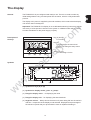

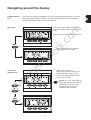
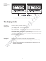


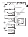
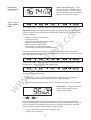

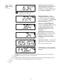
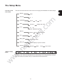
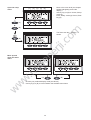


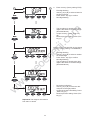
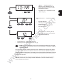
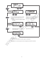

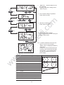
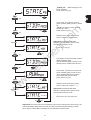
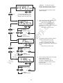


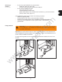
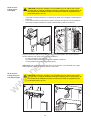
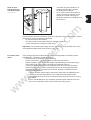

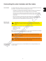
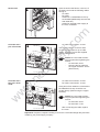

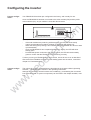
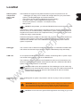
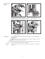
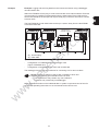


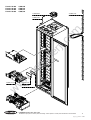
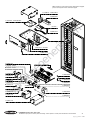

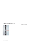
![FRONIUS IG US [42,0410,1089]](http://vs1.manualzilla.com/store/data/005774043_1-689bd6c2a055f0ab88c64924d7fd22c0-150x150.png)