1
Check the Power Budget
Verify your power budget
requirements
Calculating your power
usage
Your I/O configuration choice can be
affected by the power requirements of the
I/O modules you choose. When determining the types and quantity of I/O
modules you will be using, it is important
to remember there is a limited amount of
power available from the power supply.
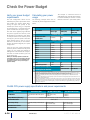
The following example shows how to
calculate the power budget for the DL405
system.
The chart on the opposite page indicates
the power supplied and used by each
DL405 device. The adjacent chart shows
an example of how to calculate the power
used by your particular system. These two
charts should make it easy for you to
determine if the devices you have chosen
fit within the power budget of your system
configuration.
A
Base Number
0
Device Type
B
5 VDC (mA)
External 24 VDC
Power (mA)
CURRENT SUPPLIED
CPU/Expansion Unit
/Remote Slave
D4-440 CPU
C
3700
400
CURRENT REQUIRED
SLOT 0
SLOT 1
SLOT 2
SLOT 3
SLOT 4
SLOT 5
SLOT 6
SLOT 7
D4-16ND2
+150
+0
D4-16ND2
+150
+0
F4-04DA
+120
+100
D4-08ND3S
+100
+0
D4-08ND3S
+100
+0
D4-16TD2
+100
+0
D4-16TD2
+100
+0
D4-16TR
+1000
+0
D4-08B
+80
+0
D4-HPP
+320
+0
E Maximum Current Required
2820
100
F Remaining Current Available
3700-2820=880
400-100=300
If the I/O you have chosen exceeds the
maximum power available from the power
supply, you can resolve the problem by
shifting some of the modules to an expansion base or remote I/O base (if you are
using remote I/O).
Warning: It is extremely important to calculate the
power budget correctly. If you exceed the power budget, the system may operate in an unpredictable manner which may result in a risk of personal injury or
equipment damage.
The example is constructed around a
single 8-slot base using the devices shown.
It is recommended you construct a similar
table for each base in your DL405 system.
D
OTHER
BASE
Handheld Programmer
1. Using a chart similar to the 3one above, fill in column 2.
2. Using the tables on the opposite page, enter the current supplied and used by each device (columns 3 and 4). Pay special attention to the current supplied by the CPU, Expansion Unit, and Remote Slave since they differ. Devices which fall into the "Other" category (Row D) are devices such
as the Base and the Handheld programmer, which also have power requirements, but do not plug directly into the base.
3. Add the current used by the system devices (columns 3 and 4) starting with Slot 0 and put the total in the row labeled "maximum current
required" (Row E).
4. Subtract the row labeled "Maximum current required" (Row E), from the row labeled "Current Supplied" (Row B). Place the difference in the row
labeled "Remaining Current Available" (Row F).
5. If "Maximum Current Required" is greater than "Current Supplied" in either column 3 or 4, the power budget will be exceeded. It will be unsafe to
use this configuration and you will need to restructure your I/O configuration. Note the auxiliary 24 VDC power supply does not need to supply all
the external power. If you need more than the 400mA supplied, you can add an external 24VDC power supply. This will help keep you within your
power budget for external power.
DL405 CPU power supply specifications and power requirements
Specification
Part Numbers
AC Powered Units
D4-450, D4-440, D4-430, D4-EX (expansion
unit)
Voltage Withstand (dielectric)
Insulation Resistance
24 VDC Powered Units
D4-440DC-1,
D4-EXDC (expansion unit)
D4-450DC-1
125 VDC Powered Units
D4-440DC-2
D4-450DC-2
1 minute @ 1,500 VAC between primary, secondary, field ground, and run relay
> 10M at 500VDC
Input Voltage Range
85-132 VAC (110 range) 170-264 VAC (220
range
20-28 VDC (24 VDC)
with less than 10% ripple
90-146 VDC (125 VDC)
with less than 10% ripple
Maximum Inrush Current
Maximum Power
20 A
20 A
20 A
50 VA
38 W
30 W
6–26
PLC Products
01737-824600
Power Requirements
PLC
Overview
DL05/06
PLC
Power Supplied
CPUs/Remote Units/
Expansion Units
5 VDC Current
Supplied in mA
24V Aux Power
Supplied in mA
CPUs/Remote
Units/Expansion Units
5V Current Supplied
in mA
24VAux. Power
Supplied in mA
D4-430 CPU
D4-440 CPU
D4-440DC-1 CPU
D4-440DC-2 CPU
D4-450 CPU
D4-450DC-1 CPU
D4-450DC-2 CPU
3700
3700
3700
3700
3100
3100
3100
400
400
NONE
NONE
400
NONE
NONE
D4-EX
D4-EXDC
D4-EXDC-2
D4-RS
D4-RSDC
H4-EBC
H4-EBC-F
4000
4000
3700
3700
3700
3470
3300
400
NONE
NONE
400
NONE
400
400
Power-consuming
Device
I/O Bases
5V Current
Consumed
External 24VD
Current Required
Power-consuming
5V Current
Device
Consumed
Analog Modules (continued)
External 24VDC
Current Required
D4-04B-1
D4-06B-1
D4-08B-1
80
80
80
NONE
NONE
NONE
F4-16AD-1
F4-16AD-2
F4-04DA
F4-04DA-1
F4-04DA-2
F4-04DAS-1
F4-04DAS-2
F4-08DA-1
F4-08DA-2
F4-16DA-1
F4-16DA-2
F4-08RTD
F4-08THM-n
F4-08THM
100
100
100
75+20per circuit
90
60 per circuit
60 per circuit
100+20 per circuit
150
100+20 per circuit
25 max.
NONE
50
60
D4-08ND3S
D4-16ND2
D4-16ND2F
D4-32ND3-1
D4-32ND3-2
D4-64ND2
100
150
150
150
150
300 max.
NONE
NONE
NONE
NONE
NONE
NONE
DL405
PLC
Field I/O
75
75
120
70
90
60
60
90
80
90
80
80
120
110
Remote I/O
100
150
NONE
NONE
150
90
NONE
NONE
H4-ERM
H4-ERM-F
D4-RM
320
450
300
DC Output Modules
D4-08TD1
F4-08TD1S
D4-16TD1
D4-16TD2
D4-32TD1
D4-32TD1-1
D4-32TD2
150
295
200
400
250
250
350
D4-64TD1
800
35
NONE
125
NONE
140
140 (15V)
120 (4A max
including loads)
NONE
AC Output Modules
D4-08TA
D4-16TA
250
450
NONE
NONE
Relay Output Modules
D4-08TR
F4-08TRS-1
F4-08TRS
D4-16TR
550
575
575
1000
NONE
NONE
NONE
NONE
Analog Modules
PLC Products
100
120
90
Motors
Steppers/
Servos
Motor
Controls
530
670
500
235
NONE
Encoders
NONE
NONE
NONE
NONE
Pushbuttons/
Lights
Process
65
CoProcessors
F4-CP128-1
F4-CP128-T
305
350
Comm.
NONE
NONE
TB’s &
Wiring
Specialty Modules
Power
H4-CTRIO
D4-INT
D4-HSC
F4-16PID
F4-08MPI
D4-16SIM
F4-4LTC
400
100
300
160
225
150
280
NONE
NONE
NONE
NONE
170
NONE
75
Enclosures
Appendix
Part Index
Programming
85
270
75
AC Drives
Relays/
Timers
D4-HPP-1 (Handheld Prog.)
F4-04AD
F4-04ADS
F4-08AD
Other HMI
Limit
Switches
Communications and Networking
H4-ECOM
H4-ECOM-F
D4-DCM
F4-MAS-MB
FA-UNICON
C-more
HMIs
Photo
Sensors
NONE
NONE
NONE
AC/DC Input Modules
D4-16NE3
F4-08NE3S
Software
Proximity
Sensors
AC Input Modules
D4-08NA
D4-16NA
DL205
PLC
DL305
PLC
Power Consumed
DC Input Modules
DL105
PLC
320
NONE
DV-1000
150
NONE
C-more Micro-Graphic
210
NONE
Operator Interface
6–27
Dimensions and Installation
It is important to understand the installation requirements for your DL405 system.
This will help ensure that the DL405 products operate within their environmental
and electrical limits.
With 32-pt. or 64-pt. solder
With-32 pt. or 64-pt. ribbon
With programming or OI cable
With 8 or 16 I/O
Plan for safety
This catalog should never be used as a
replacement for the user manual. The user
manual, D4-USER-M, contains important
safety information that must be followed.
The system installation should comply with
all appropriate electrical codes and standards.
Base dimensions
and mounting
orientation
With 8 or 16 I/O
Specification
Use the diagrams to the right to make sure
the DL405 system can be installed in your
application. To ensure proper airflow for
cooling purposes, DL405 bases must be
mounted horizontally. It is important to
check these dimensions against the conditions required for your application. For
example, it is recommended that you leave
1.5" depth for ease of access and cable
clearance. However, your distance may be
greater or less. Also, check the installation
guidelines for the recommended cabinet
clearances.
Rating
Storage Temperature
Ambient Operating Temperature
Ambient Humidity
Vibration Resistance
Shock Resistance
Noise Immunity
Atmosphere
-4°F - 158°F (-20°C to 70°C)
32°F - 140°F (0° to 60°C)
30% - 95% relative humidity (non-condensing)
MIL STD 810C, Method514.2
MIL STD810C, Method516.2
NEMA(ICS3-304)
No corrosive gases
See
the Enclosures section
of this catalog for an enclosure that may be suitable for
your application
DL405 base
Note: there is a minimum of 2" (50mm) clearance required
between the panel door or any devices mounted in the panel
door and the nearest DL405 component.
Base
D4-04B-1
D4-06B-1
D4-08B-1
6–28
PLC Products
Price
<--->
<--->
<--->
A
B
C
11.53"
293mm
10.82"
275mm
10.50"
267mm
14.44"
367mm
13.74"
349mm
13.42"
341mm
17.36"
441mm
16.65"
423m
16.32"
423mm
01737-824600
Base Configurations
PLC
Overview
DL05/06
PLC
Four, six, and
eight-slot bases
DL105
PLC
6-slot base
4-slot base
DL205
PLC
The DL405 product family offers four, six,
and eight-slot I/O bases.
Expansion units
The expansion units are only necessary
when you want to use local expansion.
They are installed in the CPU slot of the
expansion bases. They appear very
similar to CPUs, but they only contain a
power supply. One of the most often
asked questions for the DL405 family is,
“Does the CPU consume an I/O slot?”
The answer is no. The CPU has a special
slot in the base and does not consume
any of the available I/O slots. The same
is true for Expansion Units
• D4-EX 110/220 VAC power supply <--->
• D4-EXDC 24 VDC power supply
<--->
• D4-EXDC-2 125 VDC power supply <--->
DL305
PLC
CPU, Expansion Unit, or
Remote Slave Slot
I/O Slot
DL405
PLC
Base Expansion Cable
8-Slot base
Field I/O
Expansion
Connectors
Software
C-more
HMIs
Other HMI
AC Drives
Specialty modules in expansion bases
No! Must use
D4-450 CPU
No! Both bases must be
“-1” type
Motors
Yes! Uses D4-450
and “-1” bases.
Steppers/
Servos
and the Remote Slave Units
• D4-RS 110/220 VAC power supply <--->
An expansion cable is required to connect
each of the expansion bases to the CPU
base
• D4-EXCBL 3.08 ft (1m) cable
<--->
• D4-EXCBL-2 1.54 ft (0.5m) cable
<--->
Motor
Controls
D4-04B
D4-04B-1
Proximity
Sensors
D4-04B-1
D4-450 and –1 bases
Specialty
module
Specialty
module
D4-04B-1
Specialty
module
Photo
Sensors
Limit
Switches
In the past, a DL405 system has been
limited to only accepting specialty
modules in the local CPU base. The –1
bases must be used with the D4-450 CPU
to remove this limitation. The part
numbers for the bases are D4-04B-1,
D4-06B-1, and D4-08B-1. (Note: you
cannot simply add a –1 base to an
existing system to gain specialty modules
in expansion bases. Instead, you must
replace the CPU base and all other
expansion bases as well.) You can add
the –1 bases in an older system, but they
are subject to the limitations of the
regular bases.
Encoders
Pushbuttons/
Lights
Process
Relays/
Timers
Comm.
TB’s &
Wiring
Power
Enclosures
Appendix
Part Index
PLC Products
6–29