1
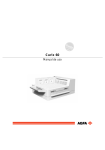
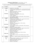
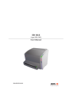
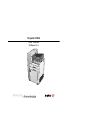
Drystar 5500
User manual
Software 2.x
This product is registered in China under the registration number:
For more information on Agfa products and Agfa HealthCare products, please visit www.agfa.com, your
Point of Knowledge.
© Agfa-Gevaert N.V. 2004.
No parts of this document may be reproduced, copied, adapted or transmitted in any form or by any means
without the written permission of Agfa-Gevaert N.V.
Agfa-Gevaert N.V. makes no warranties or representation, expressed or implied, with respect to the accuracy, completeness or usefulness of the information contained in this document and specifically disclaims
warranties of suitability for any particular purpose. Agfa-Gevaert N.V. shall under no circumstances be liable
for any damage arising from the use or inability to use any information, apparatus, method or process disclosed in this document.
Agfa-Gevaert N.V. reserves the right to make changes to this document without prior notice.
Agfa-Gevaert N.V., Septestraat 27, B-2640 Mortsel, Belgium.
Drystar 5500 is a trademark of Agfa-Gevaert N.V., Belgium.
Agfa and Agfa-Rhombus are trademarks of Agfa-Gevaert AG, Germany.
2
2901B EN 20040413
Table of contents
Chapter 1: Introducing the Drystar 5500 .......................................................... 5
Drystar 5500 features....................................................................................... 6
Safety precautions ........................................................................................... 8
Security precautions....................................................................................... 12
Safety compliance.......................................................................................... 13
Privacy and security ....................................................................................... 15
Operating modes ........................................................................................... 17
Control modes (local and remote)................................................................... 19
The user interface .......................................................................................... 20
Switching on the Drystar 5500 ........................................................................ 26
Switching off the Drystar 5500 ........................................................................ 28
Chapter 2: Basic operation (operator mode) ................................................. 29
Overview of operator functions ....................................................................... 30
Managing the print queue............................................................................... 31
Assigning emergency priority.......................................................................... 33
Deleting print jobs .......................................................................................... 34
About Drystar 5500 consumables ................................................................... 36
Loading films.................................................................................................. 38
Chapter 3: Advanced operation (key-operator mode)................................... 47
Overview of key-operator functions ................................................................ 48
Preventive maintenance schedule .................................................................. 49
Cleaning the exterior ...................................................................................... 50
Cleaning the printhead resistor line ................................................................ 51
Troubleshooting checklist ............................................................................... 54
Appendix A: Equipment information sheet.................................................... 55
Specifications ................................................................................................. 56
Options and accessories ................................................................................ 59
2901B EN 20040413
3
4
2901B EN 20040413
Chapter
Introducing the Drystar 5500
This chapter introduces the Drystar 5500 to the user and
draws attention to important safety precautions.
!
Drystar 5500 features
!
Safety precautions
!
Security precautions
!
Safety compliance
!
Privacy and security
!
Operating modes
!
Control modes (local and remote)
!
The user interface
!
Switching on the Drystar 5500
!
Switching off the Drystar 5500
1
Drystar 5500 features
The Drystar 5500 is a dry digital printer for producing diagnostic images. It
can print multiple format (8x10” up to 14x17”) blue-based and clear-based
film and offers crisp, dense grayscale images. The Drystar 5500 is designed
for high-throughput and as a central printer.
" The Drystar 5500 is a Dicom-only network printer.
The Drystar 5500 offers the following features:
# Dry technology for printing diagnostic quality hard copies in full daylight offers
important advantages: no chemistry, no wet processing, simple cleaning
procedures, no time-consuming adjustments, no darkroom and no chemical
disposal costs. The consumables can be loaded in full daylight.
# With its compact design, the Drystar 5500 needs little work space and allows
easy customer access. Maintenance and service activities are reduced to the
minimum.
# The direct thermal printing system provides grayscale images with laser-like
quality: 508 dots per inch resolution, each pixel with 12 bit contrast resolution
and an optical density ranging from 0.2 up to 3.1 (if an X-Rite 310
densitometer is used).
# The built-in image spooling on hard disk assures a high throughput. Printing
time is kept to a minimum.
# Multiple film formats (8x10”, 10x12”, 11x14”, 14x14”, and 14x17”) can be
used. Any combination of two film formats can be used “online”. Both input
trays can be adjusted for all film formats.
# The input trays of the Drystar 5500 are equipped with an RF-tag reader,
which automatically traces the films used in the printer and protects the
printer when detecting non-identified media.
# Number of input trays.
The Drystar 5500 is delivered with 2 input trays. Both input trays can use multiple
format (8x10” up to 14x17”) films.
6
Introducing the Drystar 5500
2901B EN 20040413
# Number of output trays
The Drystar 5500 is delivered with 4 output trays, which can be assigned to
modalities in any combination.
Network features
# The modular design offers optimal application to your specific networking
requirements.
In a network configuration, the Drystar 5500 is fully compatible with Agfa’s
diagnostic imaging systems, including the ADC Compact and ADC Quality System
software, the Paxport and the entire line of Impax Review Systems, Storage
Stations and Transmitting Stations.
# The functionality of the Drystar 5500 is completely controlled via the network.
# You can control the working of the Drystar 5500 via the local keypad or via a
remote PC featuring a browser functionality.
Customizable features
# Number of output trays.
The Drystar 5500 is delivered with 4 output trays and a sorter.
# Consumables.
The Drystar 5500 can handle Drystar DT2 B and Drystar DT2 C consumables, both
in multiple formats (8x10” up to 14x17”).
Software license information
# The Drystar 5500 printer uses software developed by the Apache Software
Foundation (http://www.apache.org/licenses/LICENSE).
2901B EN 20040413
Introducing the Drystar 5500
7
Safety precautions
" The Drystar 5500 must only be operated according to its specifications
and its intended use. Any operation not corresponding to the
specifications or intended use may result in hazards, which in turn may
lead to serious injuries or fatal accidents (for example electric shocks).
AGFA positively will not assume any liability in these cases.
" All images created using any image technology can show artifacts which
could be mixed up with diagnostic relevant information. If there is any
doubt that the diagnostic information could not be absolutely true,
additional investigations must be performed to get a clear diagnostic.
When operating or maintaining the Drystar 5500, always observe the
following safety guidelines:
• Have electrical or mechanical defects repaired by skilled personnel only!
• Do not override or disconnect the integrated safety features.
• Ventilation openings may not be covered.
• Always switch off the Drystar 5500 and disconnect the power cord from the
outlet before carrying out any maintenance work.
" Film jam removal or Cleaning the printer thermal head can be done
without switching the power off. Nevertheless, care should be taken and
the following instructions should be respected:
8
Introducing the Drystar 5500
2901B EN 20040413
Always take into account the markings provided on the inside and outside of
the printer. A brief overview of these markings and their meaning is given
below.
Safety warning, indicating that the Drystar 5500 manuals should be
consulted before making any connections to other equipment. The
use of accessory equipment not complying with the equivalent
safety requirements of this printer may lead to a reduced level of
safety of the resulting system. Consideration relating to the choice of
accessory equipment shall include:
• Use of the accessory equipment in the patient vicinity,
• Evidence that the safety certification of the accessory equipment
has been performed in accordance with the appropriate IEC 601-1
and IEC 601-1-2 harmonized national standard.
In addition all configurations must comply with the medical electrical
systems standard IEC 601-1-2. The party that makes the
connections acts as system configurator and is responsible for
complying with the systems standard.
If required contact your local service organization.
Caution hot:
Keep hands clear from the thermal printhead.
In order to reduce the risk of electric shock, do not remove any
covers.
Type B equipment:
Indicates that the Drystar 5500 complies with the limits for type B
equipment.
2901B EN 20040413
Introducing the Drystar 5500
9
Supplementary protective earth connector:
Provides a connection between the Drystar 5500 and the potential
equalization busbar of the electrical system as found in medical
environments. This plug should never be unplugged before the
power is turned off and the power plug has been removed.
Intergrounding connector:
Provides a connection between the printer and other equipment
which might exhibit minor ground potential differences. These
differences may degrade the quality of communication between
different equipment. Never remove connections to this terminal.
Protective earth (ground):
Provides a connection between the printer and the protective earth
of the mains. Do not remove this connection, because this will have
a negative influence on the leakage current.
Power Button:
Note that the power cord has to be disconnected from the wall outlet
in order to disconnect the unit entirely from the mains.
Precautions for use in USA only:
Make sure that the circuit is single-phase center-tapped, if the printer
is connected to a 240 V/60 Hz source instead of a 120 V/60 Hz
source.
10
Introducing the Drystar 5500
2901B EN 20040413
Transport after installation
Before moving the printer, always switch off the machine. The user has to be
very cautious concerning stability, when moving the printer. When doing this,
he has to take into account the condition and the structure of the subsoil,
obstructions and slopes. Also the user has to make sure that the brakes are
loose. The appliance can only be transported with all covers closed. The
appliance may not be transported continuously from one location to the other.
To prevent injuries, lock the brakes when the Drystar 5500 is in place at
the right location.
Waste disposal and environmental regulations
In most countries Drystar film is considered industrial waste and
consequently it is not allowed to dispose of it as household waste. Please
consult your local waste disposal regulations. Agfa recommends to have
waste Drystar film hauled away by a licensed company.
After its life span, do not dispose of the Drystar 5500 without consideration of
local waste disposal regulations. Please consult your local service
organization.
2901B EN 20040413
Introducing the Drystar 5500
11
Security precautions
CAUTION: U.S. Law restricts this device to sale to or on the order of a
licensed physician.
Printed images should be treated as patient records and should only be
viewed by authorized personnel.
It is good practice not to delete images from the modality, until they are
correctly printed.
12
Introducing the Drystar 5500
2901B EN 20040413
Safety compliance
EMC issues
• USA: This equipment has been tested and found to comply with the limits for a
class A digital device, pursuant to part 15 of the FCC rules. These limits are
designed to provide reasonable protection against harmful interference when the
equipment is operated in a commercial environment. This equipment generates,
uses, and can radiate radio frequency energy and, if not installed and used in
accordance with the Reference manual, may cause harmful interference to radio
communications. Operation of this equipment in a residential area is likely to
cause harmful interference in which case the user will be required to correct the
interference at its own expense.
If required, contact your local service organization.
• Canada: This class A digital apparatus meets all requirements of the Canadian
Interference-Causing Equipment Regulations.
• EC: This is a class A product. In a domestic environment this product may cause
radio interference in which case the user may be required to take adequate
measures.
Compliances
This equipment complies with:
• the Medical Devices Directive 93/42/EEC
• the standards UL2601-1 of Underwriters Laboratories
• CSA 22.2 No. 601.1-M90 of the Canadian Standards Association
• FDA 510k
• FDA Part 820 Good manufacturing Practice for Medical devices
• IEC 601-1 and IEC 601-1-2
• EN 60601-1:1990 + A1:1993 + A2:1995
• EN 60601-1-2:2001
• GB4943-2001
• GB9254-1998
• GB17625.1-2003
2901B EN 20040413
Introducing the Drystar 5500
13
Label
The Drystar 5500 carries the CE, TÜV and the CUL label.
To find the label location
14
1
Open the front door.
2
The label is visible inside the printer:
Introducing the Drystar 5500
2901B EN 20040413
Privacy and security
Within the healthcare industry, several standardization efforts are ongoing as
a response to Privacy and Security legislation and regulations. The purpose
of this standardization for hospitals and vendors is to enable information
sharing, interoperability and to support the workflow of hospitals in a multiple
vendor environment.
In order to allow hospitals to comply with HIPAA regulations (Health
Insurance Portability and Accountability Act) and to meet the IHE standards
(Integrated Healthcare Enterprise) some security features are included in the
user interface of the Drystar 5500 (available via the web pages only: under
‘Security tools’. Refer to ‘Controlling the Drystar 5500 via a remote PC (with
browser)’ on page 141 of the Drystar 5500 Reference manual):
• Product Authentication: HIPAA supported products that communicate with
DICOM use the Transport Layer Security (TLS) protocol. The TLS protocol uses
public key certificates for client and server authentication (X.509).
• Product Accountability: HIPAA supported products require some level of user
and system activity to be recorded. As a consequence of these actions, audit
records are be sent to and observed at an Audit Record Repository (ARR).
• Product User Authentication: 'User Authentication' of HIPAA products involves
password protection for access to User, Key operator, Service Security/
Administrator and other user interfaces that allow access to protected health
information (PHI). These interfaces include all user keypads, front panels
displays and network connections.
The last two functions are available when access to the Administrator is
granted (i.e. when the Administrator password has been correctly entered).
2901B EN 20040413
Introducing the Drystar 5500
15
Node authentication, certificates and Certification Authority
Each device - connected to a network - will receive a unique identifier: the
X.509 certificate, a digital passport. Any device on the network is only allowed
to communicate with another node of which it is holding the certificate in a
‘communication allowed’ table.
A Certification Authority (CA) is responsible for creating a certificate. The CA
can be the hospital, Agfa or a third party.
This CA distributes the certificate to the hospital security responsible or
service technician, who for his part:
• Imports the device certificate, created by the CA.
Imports the certificates of all peer devices with which communication is authorized,
i.e. creates the list of ‘communication allowed’ device certificates.
16
Introducing the Drystar 5500
2901B EN 20040413
Operating modes
The Drystar 5500 can be operated in five modes: operator mode, keyoperator mode, service mode, specialist mode, and administrator mode.
Operator mode
The operator mode groups all basic functions which are aimed at
radiographers without special technical skills:
• Producing diagnostic usable hardcopies;
• Loading consumables;
• Ensuring normal operation of the printer.
All functions of the operator mode are described in both User and Reference
manuals. Refer to Chapter 2, ‘Basic operation (operator mode)’.
Key-operator mode
The key-operator mode groups advanced functions which are aimed at
technically skilled operators such as X-ray operators, network managers and
service and hospital technicians.
The key-operator mode can be accessed via the Key-operator key on the
keypad and is menu-driven. The key-operator functions are described in the
Reference manual only. Refer to Chapter 3, ‘Advanced operation (keyoperator mode)’.
Service mode
The service mode functions are reserved for trained service personnel. The
service mode is password protected.
Specialist mode
The specialist mode functions are reserved for trained service personnel of
the Agfa Customer Support Center. The specialist mode is password
protected and is only accessible by browser via a remote PC.
2901B EN 20040413
Introducing the Drystar 5500
17
Administrator mode
The Administrator mode functions are reserved for the System Administrator.
The Administrator mode is password protected and is only accessible by
browser via a remote PC. Refer to ‘Privacy and security’ on page 15.
18
Introducing the Drystar 5500
2901B EN 20040413
Control modes (local and remote)
You can control the working of the Drystar 5500 via the local keypad or via a
network remote PC.
The table below gives an overview of the operating modes you can access
locally or via the remote PC.
Local
Password
protected
Remote
Password
protected
Operator mode
No
–––
–––
Key-operator mode
No
Key-operator mode
Yes
Service mode
Yes
Service mode
Yes
–––
–––
Specialist mode
Yes
–––
–––
Administrator mode
Yes
The manual describes the controlling of the Drystar 5500 via the keypad. The
menus for controlling the Drystar 5500 via a remote PC are structured in the
same way. Refer to ‘Controlling the Drystar 5500 via a remote PC (with
browser)’ on page 141 of the Drystar 5500 Reference manual.
2901B EN 20040413
Introducing the Drystar 5500
19
The user interface
The Drystar 5500 interfaces with the user via the following controls:
• Power button;
• Unlock button;
• a keypad and a display;
• a status indicator LED;
• audio signals.
Overview of user interface controls:
1
2
3
4
5
6
7
1
Unlock button
2
Power button
3
Display
4
Keypad cover
5
Status indicator LED
6
Film input tray (Upper input tray)
7
Film input tray (Lower input tray)
Never try to open the printer when the Drystar 5500 is busy printing a
film. Always follow the instructions on the display!
20
Introducing the Drystar 5500
2901B EN 20040413
The status indicator LED
At the right side of the display, a LED indicates the status of the Drystar 5500.
Color / Light
Status
Action
Constant
Ready (stand-by)
Proceed
Blinking
Busy or in keyoperator mode
Wait
Blinking
Warning status
Constant
Error status
Green
Red
Check the display for messages.
Refer
to
‘Controlling
the
Drystar 5500 via a remote PC
(with browser)’ on page 141 of the
Drystar 5500 Reference manual.
The control buttons
Two control buttons have been provided
Unlock button
• To safely unlock the printer for accessing the
input trays or opening the covers.
Power button
• To power on or off the printer.
Do NOT press the Power button without first following the procedure to
stop printing when the Drystar 5500 is busy printing a film. Refer to
‘Switching off the Drystar 5500’ on page 28.
2901B EN 20040413
Introducing the Drystar 5500
21
Audio signals
The Drystar 5500 gives status information via beeps. The length of the beep
indicates the response of the system to a key command.
• A short beep means that Drystar 5500 has accepted the key command and is
starting the operation.
• A long beep means that you have pressed a non-active key or that the
Drystar 5500 has rejected the key command.
" Certain conditions can cause an interval beep. An interval beep
accompanies an error or warning message. Refer to ‘Troubleshooting
checklist’ on page 164 of the Drystar 5500 Reference manual.
The keypad
To access the keypad, push the keypad cover backward.
The keypad is located under the keypad cover.
The Drystar 5500 keypad features the following keys:
22
Introducing the Drystar 5500
Emergency
key
To rearrange the print queue: emergency jobs can
be placed at the top of the queue to be printed with
priority. Refer to ‘Assigning emergency priority’ on
page 33.
Delete key
To delete print jobs. Jobs that are deleted will not be
printed. Refer to ‘Deleting print jobs’ on page 34.
Keyoperator key
To access the advanced functions of the keyoperator mode. Refer to Chapter 3, ‘Advanced
operation (key-operator mode)’.
2901B EN 20040413
Service key
To access service-level functions. Reserved for
trained service personnel.
Escape key
To quit the current function or exit a menu without
saving modifications.
Confirm key
(In key-operator mode)
• To select a menu;
• To accept an entry in a menu.
Up key
• To move the cursor to the previous entry field.
• To scroll upwards.
• To increment the number in a(n) (alpha)numerical
entry field.
Down key
• To move the cursor to the next entry field.
• To scroll downwards.
• To decrement the number in a(n)
(alpha)numerical entry field.
Left key
• To scroll backwards through multiple choices
within a field.
• To move the entry position in a(n)
(alpha)numerical entry field from right to left.
• To toggle between values in a field.
Right key
• To scroll forwards through multiple choices within
a field.
• To move the entry position in a(n)
(alpha)numerical entry field from left to right.
• To toggle between values in a field.
" You can press and hold down an arrow key to scroll quickly through a list
or a menu.
2901B EN 20040413
Introducing the Drystar 5500
23
The display
The Drystar 5500 control panel has a backlit LCD display with 8 lines of
40 characters each. Its lay-out depends on the operating mode.
Operator mode
In operator mode, appropriate information is displayed, in accordance with
the status of the printer.
The operator basic screen looks as follows, indicating that the Drystar 5500 is
ready for operation and that no job is currently being executed.
READY
During printing, calculation and other processes, as the printer is busy with at
least one job, the Print queue screen is displayed:
Modality name
10:21:34 PRINTING
film 15 of 22
62%
Modality name
Modality name
Modality name
Modality name
10:21:34
10:23:12
10:24:45
10:31:01
CALCULATING
WAITING
WAITING
WAITING
• The progress indicator keeps the user informed of the progress of a process
(e.g., calculation of a bitmap, printing of a film, copying files). The line is
gradually filled from left to right, from 0% to 100% as the process proceeds.
" On the print queue screen the modality name defined during installation
will be used to refer to the corresponding modality. In case there is also a
nickname (daily used name) defined during installation, the nickname is
used.
Refer to ‘Managing the print queue’ on page 31.
24
Introducing the Drystar 5500
2901B EN 20040413
Key-operator mode
In key-operator mode, operation is menu driven. The menu displays the
key-operator functions and the active keys.
1
2
3
4
5
6
7
8
1
Stop Printing
Show settings
Change settings
Print image
Save configuration
Restore configuration
Calibration
Installation
Key-Operator
Main Menu
quit
ok
select
1
Key-operator main menu functions
2
Active keys
2
Data entry
When entering numerical or alphanumerical data, always adhere to the
following principles:
• Only (alpha)numerical data can be entered.
• During the data entry, the field is displayed in reverse mode.
• Increment the number in a(n) (alpha)numerical entry field by pressing the Up
key. Transition from 9 to 0 of one figure will also increment the next figure to the
left, respecting the valid limits of the range.
• Decrement the number in a(n) (alpha)numerical entry field by pressing the Down
key. Transition from 0 to 9 of one figure will also decrement the next figure to the
left, respecting the valid limits of the range.
• Move the entry position in a(n) (alpha)numerical entry field from right to left by
pressing the Left key.
• Move the entry position in a(n) (alpha)numerical entry field from left to right by
pressing the Right key.
• Press and hold down a key to repeat arrow key actions.
• To accept an entry in a menu, press the Confirm key.
• A short beep acknowledges and terminates the entry.
• The Drystar 5500 will sound a long beep if you press a key that is not to be used
at that moment.
2901B EN 20040413
Introducing the Drystar 5500
25
Switching on the Drystar 5500
" Before switching on the Drystar 5500, read the safety instructions. Refer
to ‘Security precautions’ on page 12.
Follow the procedure below to ensure proper startup of the Drystar 5500 and
to check that everything is working correctly.
1
Check that the power cord is plugged in and then switch on the printer by
pressing the Power button.
On the display, the following message is displayed. After a short while, a progress
indicator will show the proceeding of the self test.
Please WAIT
Self test proceeding
62%
2
The printer is ready for operation:
• If, on the front panel display, the READY message is shown, the status indicator
LED is constant green.
READY
" It takes 13 minutes (starting up of the Drystar 5500 and heating up of the
printhead) before you can start printing. When you send print jobs to the
Drystar 5500 during this period, the display will inform you that the printer
is warming up.
26
Introducing the Drystar 5500
2901B EN 20040413
• If, on the front panel display, the Print queue screen is shown, the status
indicator LED is green and blinking.
3
Modality name
10:21:34 PRINTING
film 15 of 22
62%
Modality name
Modality name
Modality name
Modality name
10:21:34CALCULATING
10:23:12 WAITING
10:24:45 WAITING
10:31:01 WAITING
Make sure that the printer is loaded with appropriate consumables.
" Refer to page 38 for detailed information on loading films.
" If the job status holds a warning or error indication: refer to
‘Troubleshooting checklist’ on page 164 of the Drystar 5500 Reference
manual.
2901B EN 20040413
Introducing the Drystar 5500
27
Switching off the Drystar 5500
When you want to switch off the printer, it is recommended to follow the
procedure as described below, to make sure that any pending jobs are
correctly finished.
1
Make sure that the pending jobs are correctly finished. If necessary, follow
the procedure to stop printing. Refer to ‘Stopping the printing process’ on
page 51 of the Drystar 5500 Reference manual.
2
Press the Power button to switch off the Drystar 5500.
" In case the printer is ready, it shuts down immediately. Otherwise it can
take 20 seconds to power down.
28
Introducing the Drystar 5500
2901B EN 20040413
Chapter
Basic operation
(operator mode)
This chapter will inform on how to manage the print queue,
how to print films with priority and how to load new films.
!
Overview of operator functions
!
Managing the print queue
!
Assigning emergency priority
!
Deleting print jobs
!
About Drystar 5500 consumables
!
Loading films
2
Overview of operator functions
This section focuses on the basic operating principles of the Drystar 5500.
After reading this chapter, the operator should be able to produce diagnostic
usable hardcopies. No special technical skills are required.
All basic operator functions can be activated directly by pressing a single key
on the keypad.
Function / Task
30
Description
Page
‘Managing the print queue’
Jobs that have been received are
put in a print queue, waiting to be
printed.
31
‘Assigning emergency priority’
To rearrange the order in which
jobs are waiting to be printed. Jobs
that have emergency priority are
placed on top of the print queue.
33
‘Deleting print jobs’
To remove print jobs from the print
queue. Print jobs that are deleted
will not be printed.
34
‘Loading films’
Instructions for loading new films
on the printer.
38
Basic operation (operator mode)
2901B EN 20040413
Managing the print queue
You can always check the status of the print jobs.
As long as the jobs are not yet submitted for printing (i.e. they are still in the
‘waiting’ status), you can assign emergency priority and delete individual print
jobs.
" Keep in mind that one print job can hold several films to be printed. In
accordance with the acquisition modality used, and the actual settings,
films can be grouped in a folder to be submitted as one print job for the
Drystar 5500. Refer to the User manual of the acquisition modality for
more information.
Checking the print queue
If jobs have been transmitted from the network to the Drystar 5500, they are
put in the print queue on a first in, first out schedule. New jobs that are added
to the queue get the ‘waiting’ status.
As soon as the last film of a job is ejected in the output tray, the next job that
has been calculated will be put in printing status.
Example of the Print queue screen:
Modality name
10:21:34
PRINTING
film 15 of 22
62%
Modality name
Modality name
Modality name
Modality name
2901B EN 20040413
10:21:34
10:23:12
10:24:45
10:31:01
CALCULATING
WAITING
WAITING
WAITING
Basic operation (operator mode)
31
• The first line shows information on the job that is currently being printed:
modality name, a nickname (if defined), time of receipt of the job and the job
status.
• The second line shows how many films are to be printed for the current job, and
also what film from that total is currently being printed.
• On the third line you can watch the progress of the printing process. The
progress indicator is gradually filled from left to right, from 0% to 100% as the
process is completed. If no job is being printed, the progress indicator will show
the proceeding of the calculation process of the next job.
The other lines give information on the jobs that are still waiting in the print
queue. A description of the possible status of each job is listed in the table
below:
Status
Description
Printing
Printing of this job is in
progress.
Calculating
The necessary calculations
are being made before
printing of the job can be
started.
Action
Wait.
Waiting
The job has been put in the
print
queue,
but
no
processing is yet being
done.
Wait.
• To put emergency jobs on top of
the queue, refer to ‘Assigning
emergency priority’ on page 33.
• To remove jobs from the queue,
refer to ‘Deleting print jobs’ on
page 34.
Media size
indication
No compatible media are
loaded for the print job.
Make sure the correct media are
loaded.
" On the print queue screen the modality name defined during installation
will be used to refer to the corresponding modality. In case there is also a
nickname (daily used name) defined during installation, the nickname is
used.
" If the job status holds a warning or error indication: refer to ‘Error
messages while the printer starts up’ on page 186 of the Drystar 5500
Reference manual.
32
Basic operation (operator mode)
2901B EN 20040413
Assigning emergency priority
You can assign emergency priority to jobs that need to be printed with
urgency. Jobs that are marked for priority handling are placed at the top of the
print queue for immediate processing. Emergency jobs will be printed before
other jobs that were received previously. However, any pending jobs that are
already being calculated or scheduled for printing will be finished first.
1
On the keypad, press the Emergency key.
The Emergency printing screen is displayed:
Modality
Modality
Modality
Modality
Modality
Modality
Modality
!
name
name
name
name
name
name
name
10:23:02
10:23:34
10:24:02
10:24:34
10:25:34
10:26:34
10:27:34
EMERGENCY
PRINTING
quit
ok
select
" Only the jobs that have the ‘waiting’ status are displayed. Print jobs which
already have an emergency status are blinking.
You can press the Escape key to return to the previous menu without making changes in
the job order (‘Quit’).
2
Press the Down and Up keys to scroll through the jobs and press the Confirm
key to select the job that must be printed with emergency priority.
Printing will be resumed in accordance with the changed queue order.
2901B EN 20040413
Basic operation (operator mode)
33
Deleting print jobs
You can remove jobs from the print queue if they are in the ‘waiting status’.
Any pending jobs that are already being calculated or scheduled for printing
will be finished. Such jobs can not be deleted.
1
On the keypad, press the Delete key.
The Delete print job screen is displayed:
Modality
Modality
Modality
Modality
Modality
Modality
Modality
!
name
name
name
name
name
name
name
10:23:02
10:24:34
10:24:54
10:25:34
10:26:34
10:27:34
10:28:34
DELETE
PRINT JOB
quit
ok
select
" Only the jobs that have the ‘waiting’ status are displayed.
" The modality name defined during installation will be used to refer to the
corresponding modality. In case there is also a nickname (daily used
name) defined during installation, the nickname is used.
You can press the Escape key to return to the previous menu without deleting print jobs
(‘Quit’).
2
34
Press the Down and Up keys to scroll through the jobs and press the Confirm
key to select the job that must be deleted.
Basic operation (operator mode)
2901B EN 20040413
The Confirm delete screen is displayed.
Delete selected job ?
Modality name
10:23:02
DELETE
PRINT JOB
cancel
confirm
You can press the Escape key to return to the previous menu without deleting print jobs
(‘Cancel’).
3
Press the Confirm key to delete the print job.
Printing will be resumed. The job that has been deleted will not be printed.
2901B EN 20040413
Basic operation (operator mode)
35
About Drystar 5500 consumables
The Drystar 5500 can handle blue-transparent and clear-transparent films.
Available film formats are 8x10”, 10x12”, 11x14”, 14x14”, and 14x17”.
Both input tray can use all film formats.
The key-operator can adjust the film size setting for both input trays. Refer to
‘Changing the configuration settings’ on page 61 of the Drystar 5500
Reference manual.
Labeling the input trays
The following film types can be used:
Drystar DT2 B
8x10” up to 14x17”
Drystar DT2 C
8x10” up to 14x17”
Drystar DT2 B
8x10” up to 14x17”
Drystar DT2 C
8x10” up to 14x17”
Upper input tray
Lower input tray
36
Basic operation (operator mode)
2901B EN 20040413
Appropriate labels have been applied on the input tray(s) by the service
personnel at installation of the printer, indicating the type of new film to be
loaded when the tray is empty.
2901B EN 20040413
Basic operation (operator mode)
37
Loading films
This section describes how to load the Drystar 5500 with appropriate films.
The Drystar 5500 can be loaded with 8x10”, 10x12”, 11x14”, 14x14” and
14x17” films.
" The Drystar 5500 can be loaded with new films in full daylight. Loading
films is easy and can be done in no time. Follow the procedures as
described in this section.
The Drystar 5500 will inform you in several ways that a film tray is empty:
• An audible signal (5 long beeps),
• the Status indicator LED is flashing (red color),
• the Unlock button LED is flashing,
• the display screen shows a message informing you that either the upper or lower
input tray is empty.
The film loading procedure is identical for both input trays. In the examples
below, we will assume that the lower input tray is to be loaded.
" The procedure is slightly different, depending on the fact wether the
Drystar 5500 is printing/calculating or in the ready state.
" When the printer is in the ready state, go to Step 5.
Make sure not to load more than one film pack in an input tray. Loading
more than one film pack in an input tray may damage the Drystar 5500.
38
Basic operation (operator mode)
2901B EN 20040413
When the Drystar 5500 is printing or calculating:
1
The display shows the following message:
LOWER INPUT TRAY EMPTY
PRESS THE UNLOCK BUTTON TO
START LOADING PROCEDURE
INPUT TRAY IS LOCKED
2
Press the Unlock button to initiate the loading sequence.
3
Wait while the printer is finishing printing any current jobs.
Modality name
10:21:34
PRINTING
film 15 of 22
62%
LOADING SEQUENCE IS INITIATED
Blinking
Finishing current print job
DO NOT OPEN THE INPUT TRAY YET !
When the filmpath is cleared, the following message is displayed:
LOWER INPUT TRAY EMPTY
INPUT TRAY IS UNLOCKED
OPEN INPUT TRAY
4
Blinking
Go to step 7.
2901B EN 20040413
Basic operation (operator mode)
39
When the Drystar 5500 is in the ready state:
5
The display shows the following message:
LOWER INPUT TRAY EMPTY
PRESS THE UNLOCK BUTTON TO
START LOADING PROCEDURE
6
Press the Unlock button to initiate the loading sequence.
From here on, the procedure is identical for the two cases.
7
The printer is ready to receive a new film pack when the following message
appears:
LOWER INPUT TRAY EMPTY
INPUT TRAY IS UNLOCKED
OPEN INPUT TRAY
Blinking
" You have 3 seconds to open the input tray. If you do not open the tray
within that time, the first screen (step 1 or 5 respectively) is presented
again, or printing is resumed when a job is received for which media is
available.
40
Basic operation (operator mode)
2901B EN 20040413
8
Open the empty input tray.
The display shows the following message:
Remove protective sheet from tray
LOAD NEW FILM PACK
Blinking
Close input tray
9
Remove the white (protective) film sheet.
2901B EN 20040413
Basic operation (operator mode)
41
10 Take film pack, and open it.
" Verify that the film type on the film pack corresponds with the sticker on
the tray! If you do use an other film type, you are advised to change the
label on the tray.
" You can put the film pack onto a table to make manipulation easier.
Before you do this, make sure that the table is dust-free!
11 Remove the sticker from the film pack.
42
Basic operation (operator mode)
2901B EN 20040413
12 Remove the plastic film bag partially.
13 Slide the film pack into the input tray, and remove the plastic film bag
completely.
2901B EN 20040413
Basic operation (operator mode)
43
14 Tear the plastic tape from around the film pack.
15 Close the input tray.
" The Drystar 5500 resumes printing as soon as the tray is closed.
" Loading instructions are also available on the input tray cover.
44
Basic operation (operator mode)
2901B EN 20040413
Checking the correct position of a film in the input tray
" You can verify that the film is properly loaded by watching the lower right
corner of the films in the input tray. The rounding of this corner should be
smaller than the other three corners. This is also indicated on the sticker
at the right side of the input tray cover.
" When a new film is loaded, the Film Identification tag is read and the
printer settings are automatically adjusted. The Film Identification tag is
located on the protective sheet on the backside of the film pack. The
figure below shows the film pack upside down.
2901B EN 20040413
Basic operation (operator mode)
45
46
Basic operation (operator mode)
2901B EN 20040413
Chapter
Advanced operation
(key-operator mode)
This chapter gives an overview of functions for the
advanced user:
!
Overview of key-operator functions
!
Preventive maintenance schedule
!
Cleaning the exterior
!
Cleaning the printhead resistor line
!
Troubleshooting checklist
3
Overview of key-operator functions
The key-operator menus make it possible to use the Drystar 5500 advanced
functions. The functions are described in detail in the Drystar 5500 Reference
manual.
For general information on the functions of the keys on the Drystar 5500,
refer to ‘The user interface’ on page 20.
Overview
The Drystar 5500 features the following functions on the main menu level of
the key-operator mode:
Menu item
Function
Page
Stop Printing
To halt the printing procedure
51
Show settings
To consult the current settings of the printer.
52
Change settings
To change the current settings of the printer.
61
Print Image
To print one of the standard Drystar 5500 test
images. To load and print images from a
diskette.
96
Save configuration
To make a backup of the printer settings.
102
Restore
configuration
To restore the backup of the printer settings.
105
Calibration
To calibrate the printer.
188
Installation
To install the software with the installation
wizard.
119
Refer to the indicated page of the Drystar 5500 Reference manual for an
explanation of the function and the appropriate procedures.
48
Advanced operation (key-operator mode)
2901B EN 20040413
Preventive maintenance schedule
Maintenance and cleaning involve only some minor user tasks. Refer to the
following pages for the appropriate cleaning procedure.
Interval
What to do?
Page
Ad hoc
‘Cleaning the exterior’
50
When image quality tends to
degrade. An appropriate warning
message is displayed.
‘Cleaning the printhead resistor
line’
51
When image quality tends to
degrade. An appropriate warning
message is displayed
(refer
to the Drystar 5500
Reference manual).
‘Printhead profile calibration’
116
Safety guidelines
To prevent damage to the printer while performing maintenance, observe
the following safety precautions:
• Do not lubricate the printer.
• Do not attempt to disassemble the printer.
• Do not touch the resistor line of the printhead.
• Always switch off the Drystar 5500 and disconnect the power cord from the
outlet before carrying out any maintenance work.
" Film jam removal or cleaning the printer head can be done without
switching the power off.
2901B EN 20040413
Advanced operation (key-operator mode)
49
Cleaning the exterior
1
Switch off the Drystar 5500 by following the procedure as described in
‘Switching off the Drystar 5500’ on page 28.
2
Remove the power plug from the socket.
3
Wipe the exterior of the printer with a clean, soft, damp cloth.
Use a mild soap or detergent if required but never use an ammonia–based cleaner.
Be careful not to get any liquid in the power cord port.
4
50
Plug in the printer and switch it on by following the procedure as described in
‘Switching on the Drystar 5500’ on page 26.
Advanced operation (key-operator mode)
2901B EN 20040413
Cleaning the printhead resistor line
ning
Printhead cleaning must be done when image quality problems occur.
For more information on maintaining image quality: refer to ‘Maintaining
image quality and resolving Image quality problems’ on page 188 of the
Drystar 5500 Reference manual.
To clean the printhead:
1
Press the Key-operator key to enter the key-operator mode.
2
On the Key-operator Main menu, press the Down key six times, followed by
the Confirm key to select ‘Calibration’.
1 Stop printing
2 Show settings
3 Change settings
4 Print image
5 Save configuration
6 Restore configuration
7 Calibration
8 Installation
Key-operator
Main menu
quit
ok
select
The ‘Select Calibration’ screen appears:
SELECT CALIBRATION
1 Film
2 Printhead profile
3 Printhead cleaning
3
Key-operator
Calibration
quit
ok
select
Press the Down key two times to select ‘Printhead cleaning’ and press the
Confirm key. The printer will automatically shut down.
2901B EN 20040413
Advanced operation (key-operator mode)
51
4
The ‘Printhead cleaning’ screen will give instructions on what to do:
Printhead cleaning
1. Open TPH Compartment
2. Clean printhead
3. Close the door after cleaning
5
Open the drum compartment door by pulling its handle.
6
Locate and check on sight the printhead resistor line.
" Be careful not to touch the printhead resistor line.
52
Advanced operation (key-operator mode)
2901B EN 20040413
7
Clean the printhead resistor line.
Gently pass over the resistor line a few times with a lint free cloth, slightly
moistened with Isopropyl alcohol or Ethanol. Do this only in one direction, i.e.
from left to right, without lifting the cloth.
" Do not apply any pressure on the printhead because this pressure may
cause damage on the interconnections underneath the printhead.
8
Close the drum compartment door.
After you have cleaned the printhead resistor line and you have closed the drum
compartment door, the printer will restart automatically.
" If residue dust is present as part of the cleaning procedure it will
disappear after a few prints.
2901B EN 20040413
Advanced operation (key-operator mode)
53
Troubleshooting checklist
The table below lists some general problems which can occur when working
with the Drystar 5500. Refer to the appropriate pages of the Drystar 5500
Reference manual.
• The Drystar 5500 does not print.
Action
Check the Drystar 5500
Remove a jammed film
Resolve error messages
Refer to
Page
‘The Drystar 5500 does not print’
166
‘Film input tray feed jams’
169
‘Film transport jams in the front
section’
172
‘Film transport jams in the print
section’
173
‘Film transport jams in output
section’
177
‘Unauthorized opening of the
printer’
185
‘Check the display messages.’
166
• The quality of the printed images is bad (printing remains possible).
Action
Resolve film quality problems
Resolve warning messages
Refer to
Page
‘White dots or lines appear in the
transport direction’
191
‘Low frequency banding’
191
‘Scratches appear on film’
191
‘Warning messages’
192
Have electrical or mechanical defects repaired by skilled personnel only!
54
Advanced operation (key-operator mode)
2901B EN 20040413
Appendix
Equipment information sheet
A
Specifications
Product description
Type of product
Printer
Commercial name
Drystar 5500
Original seller/manufacturer
Agfa-Gevaert N.V.
Labeling
TÜV-Certification Mark
ULC-listing Mark
Dimensions
Dimensions (approx. values in cm)
• Unpacked: width 75, length 70,
height 141
• Packed: width 90, length 83,
height 160
Weight
• Unpacked: approx. 190 kg
• Packed: approx. 235 kg
Hard disk capacity
18 GByte
Floppy disk capacity
2HD 1.44 Mbyte floppy disks
RAM memory
2x256 MB
Floppy disk container
Four 2HD 1.44 Mbyte floppy disks
Electrical connection
Operating voltage
100-120 V; 220-240 V AC
Mains fuse protection
56
220-240 V operation
16/15 A slow blow, max.
100-120 V operation
16/15 A slow blow, max.
Mains frequency
50/60 Hz
Equipment information sheet
2901B EN 20040413
Network connectivity
Ethernet / connectors
RJ45 twisted pair for 10/100Base-TX;
Serial RS232 connection
Network protocols (TCP/IP services)
FTP, Telnet, HTTP, SNMP, SMTP, LPD
Image formats
Dicom (Default)
TIFF
Postscript
Optional
Power consumption
During operation
350 W
Maximum
700 W
In standby
140 W
Protection against
Electrical shocks
Class 1 (grounded)
Ingress of water
IPXØ
Environmental conditions (operation)
Room temperature
Between +10°C and +30°C
Relative humidity
Between 10% and 80%
Atmospheric pressure
70 kPa - 106 kPa
Environmental conditions (transport and storage)
Room temperature
Between -25°C and 55°C (storage)
Between -25°C and 70°C (transport)
Relative humidity
Between 10% and 100%
Note: Films may not become wet!
Atmospheric pressure
70 kPa - 106 kPa
Noise emission (method of measurement in accordance with DIN 45635 part 19)
During operation
Max. 55 dBA
In standby
Max. 45 dBA
2901B EN 20040413
Equipment information sheet
57
Consumables
Drystar DT2 B and Drystar DT2 C
8x10” up to 14x17” film sizes
Film throughput
14x17”
> 100/h
Access time
1 film 14x17”
Max. 90 sec.
4 films 14x17”
Max. 200 sec.
Print technology
Direct thermal printing
Reliability
58
Estimated product life
(if regularly serviced and maintained
according to Agfa instructions)
> 5 years and > 150 000 films
Service interventions
Max. 2 interventions / 3 years
Earthquake kit (standard)
Meets the CA requirements
Equipment information sheet
2901B EN 20040413
Options and accessories
Mobile installation kit
The default mobile installation kit allows you to use the printer in a van. Safe
transportation is ensured by a mechanical system blocking the printhead.
Connectivity with Agfa equipment
• Paxport
• MG3000
• Drystar 2000
• Drystar 3000
• Drystar 4500
• ADC 70
• ADC Compact
• ADC Compact Plus
• ADC Solo
• Impax
• DR-Thorax
Connectivity with non-Agfa equipment
Drystar 5500 is a Dicom printer and can therefore be connected to all
modalities supporting Dicom. Although, to ensure optimal operation and
image quality, Agfa has made the effort to test and release the Drystar 5500
with most of the modalities on the market. For the complete list or if you want
to check on a specific modality, contact your Agfa representative.
2901B EN 20040413
Equipment information sheet
59
Printed in Belgium
Published by Agfa-Gevaert N.V., B-2640 Mortsel-Belgium
2901B EN 20040413