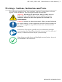
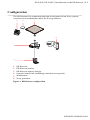
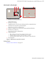
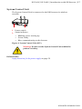
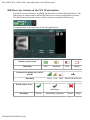
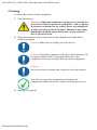
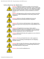
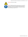
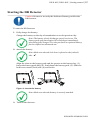
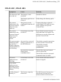
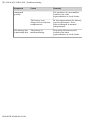
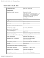
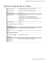
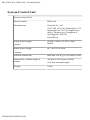
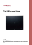
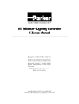
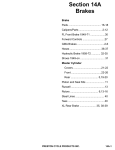
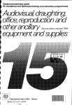
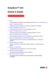
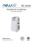
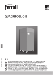
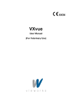
1
DX-D 40C, DX-D 40G
FXRD-1417WA
FXRD-1417WB
User Manual
0290A EN 20140626 1622
2 | DX-D 40C, DX-D 40G | Contents
Contents
Legal Notice
..........................................................................4
Introduction to this Manual
................................................... 5
Scope
.........................................................................6
Documentation by the manufacturer
..............6
Warnings, Cautions, Instructions and Notes
...............7
Disclaimer
................................................................. 8
Introduction to the DR Detector
.............................................9
Intended Use
........................................................... 10
Intended User
.......................................................... 10
Configuration
.......................................................... 11
Equipment Classification
......................................... 12
Non-medical equipment
.............................. 12
Options and Accessories
...........................................13
Recommended grid specifications
................13
Operation Controls
.................................................. 14
DX-D 40C, DX-D 40G
................................... 15
DR Detector Battery Charger
........................16
System Control Unit
.....................................17
DR Detector Switch on the NX Workstation
....
18
System Documentation
............................................19
Documentation by the manufacturer
............19
Training
...................................................................20
Product Complaints
................................................. 21
Compatibility
...........................................................22
Compliance
............................................................. 23
Documentation by the manufacturer
............23
Connectivity
............................................................ 24
Wireless Communication
............................. 25
Wired communication
................................. 26
Installation
.............................................................. 27
Environment of Use
..................................... 27
Messages
................................................................. 29
Labels
...................................................................... 30
DR Detector identification label
................... 31
Documentation by the manufacturer
............32
Cleaning and Disinfecting
........................................ 33
Cleaning
...................................................... 34
Use of protective plastic bag
.........................35
Disinfecting
................................................. 36
Approved disinfectants
................................ 37
Safety directions for disinfection
..................38
Maintenance
............................................................40
Daily inspection
........................................... 41
Half-yearly inspection
..................................42
0290A EN 20140626 1622
DX-D 40C, DX-D 40G | Contents | 3
Regular Inspection and Maintenance
........... 43
Replacement Parts Support
..........................44
Repair
..........................................................45
Environmental Protection
........................................ 46
Safety Directions
......................................................48
DR Detector Battery
..................................... 51
Safety directions for the power supply
......... 53
Safety directions for the System Control Unit
...
55
Getting started
.....................................................................56
Starting the DR Detector
..........................................57
Basic Workflow DR Detector
.................................... 59
Step 1: retrieve the patient info
....................60
Step 2: select the exposure
...........................60
Step 3: prepare the exposure
........................61
Step 4: check the exposure settings
.............. 62
Step 5: execute the exposure
........................63
Positioning the DR Detector
......................... 64
Guidelines for Pediatric Applications
....................... 67
Stopping the DR Detector
........................................ 69
Advanced Operating
............................................................ 70
Detector Status Indicators
........................................71
Charging a battery
................................................... 72
Problem solving
...................................................................73
Artifact in DR Detector images
................................. 74
DX-D 40C, DX-D 40G
.............................................. 75
Technical Data
.....................................................................77
DX-D 40C, DX-D 40G
............................................... 78
DX-D 40C, DX-D 40G Battery
................................... 80
DX-D 40C, DX-D 40G Battery Charger
......................81
System Control Unit
.................................................82
Remarks for HF-emission and immunity
.............................. 83
Documentation by the manufacturer
....................... 83
0290A EN 20140626 1622
4 | DX-D 40C, DX-D 40G | Legal Notice
Legal Notice
0434
Vieworks Co., Ltd. #107-108, 601-610, Suntechcity 2, 52 Sagimakgol-ro
(307-2, Sangdaewon-dong), Jungwon-gu, Seongnam-si, Gyeonggi-do,
462-736, South Korea
For more information on Agfa products and Agfa HealthCare products, please
visit www.agfa.com.
Agfa and the Agfa rhombus are trademarks of Agfa-Gevaert N.V., Belgium or
its affiliates. DX-D 40G and DR 40C are trademarks of Agfa HealthCare N.V.,
Belgium or one of its affiliates. All other trademarks are held by their
respective owners and are used in an editorial fashion with no intention of
infringement.
Agfa HealthCare N.V. makes no warranties or representation, expressed or
implied, with respect to the accuracy, completeness or usefulness of the
information contained in this document and specifically disclaims warranties
of suitability for any particular purpose. Products and services may not be
available for your local area. Please contact your local sales representative for
availability information. Agfa HealthCare N.V. diligently strives to provide as
accurate information as possible, but shall not be responsible for any
typographical error. Agfa HealthCare N.V. shall under no circumstances be
liable for any damage arising from the use or inability to use any information,
apparatus, method or process disclosed in this document. Agfa HealthCare
N.V. reserves the right to make changes to this document without prior notice.
The original version of this document is in English.
Copyright 2014 Agfa HealthCare N.V
All rights reserved.
Published by Agfa HealthCare N.V.
B-2640 Mortsel - Belgium.
No part of this document may be reproduced, copied, adapted or transmitted
in any form or by any means without the written permission of Agfa
HealthCare N.V.
0290A EN 20140626 1622
DX-D 40C, DX-D 40G | Introduction to this Manual | 5
Introduction to this Manual
Topics:
•
•
•
Scope
Warnings, Cautions, Instructions and Notes
Disclaimer
0290A EN 20140626 1622
6 | DX-D 40C, DX-D 40G | Introduction to this Manual
Scope
This manual contains information for the safe and effective operation of the
DX-D 40C and DX-D 40G wireless DR Detectors and peripheral equipment,
further referred to as the DR Detector.
Documentation by the manufacturer
For complete safety directions and technical documentation, refer to the
ViVIX-S 1417W User Manual that is delivered with the product.
0290A EN 20140626 1622
DX-D 40C, DX-D 40G | Introduction to this Manual | 7
Warnings, Cautions, Instructions and Notes
The following samples show how warnings, cautions, instructions and notes
appear in this document. The text explains their intended use.
Warning: Warnings are directions which, if they are not
followed, can cause fatal or serious injuries to a user,
engineer, patient or any other person or can lead to a
mistreatment.
Caution: Cautions are directions which, if they are not followed,
can cause damage to the equipment described in this manual or
any other equipment or goods and can cause environmental
pollution.
Instruction: This sign is typically used in combination with the
warning sign when providing a specific instruction. If it is followed
exactly, it should avoid the subject of the warning.
Note: Notes provide advice and highlight unusual points. A note is
not intended as an instruction.
0290A EN 20140626 1622
8 | DX-D 40C, DX-D 40G | Introduction to this Manual
Disclaimer
Agfa assumes no liability for use of this document if any unauthorized changes
to the content or format have been made.
Every care has been taken to ensure the accuracy of the information in this
document. However, Agfa assumes no responsibility or liability for errors,
inaccuracies or omissions that may appear in this document. To improve
reliability, function or design Agfa reserves the right to change the product
without further notice. This manual is provided without warranty of any kind,
implied or expressed, including, but not limited to, the implied warranties of
merchantability and fitness for a particular purpose.
Caution: In the United States, Federal law restricts this device to
sale by or on the order of a physician.
0290A EN 20140626 1622
DX-D 40C, DX-D 40G | Introduction to the DR Detector | 9
Introduction to the DR Detector
Topics:
•
•
•
•
•
•
•
•
•
•
•
•
•
•
•
•
•
•
•
Intended Use
Intended User
Configuration
Equipment Classification
Options and Accessories
Operation Controls
System Documentation
Training
Product Complaints
Compatibility
Compliance
Connectivity
Installation
Messages
Labels
Cleaning and Disinfecting
Maintenance
Environmental Protection
Safety Directions
0290A EN 20140626 1622
10 | DX-D 40C, DX-D 40G | Introduction to the DR Detector
Intended Use
The DR Detector is a wired and wireless radiographic digital X-ray imaging
device commonly referred to as flat panel detector. It is designed for all
general radiography applications. The DR Detector will be used in a
radiological environment by qualified staff to capture the X-ray images and
send these images to the imaging processing software.
The DR Detector is not intended for mammography applications.
Intended User
This manual is written for trained users of Agfa products. Users are considered
as the persons who actually handle the equipment as well as the persons
having authority over the equipment. Before attempting to work with this
equipment, the user must read, understand, note and strictly observe all
warnings, cautions and safety markings on the equipment.
Only a physician or a legally certified operator should use this product.
0290A EN 20140626 1622
DX-D 40C, DX-D 40G | Introduction to the DR Detector | 11
Configuration
The DR Detector is a component that can be integrated in an X-ray system,
connected to a workstation and to the X-ray generator.
3
2
1
6
4
5
1.
2.
3.
4.
5.
6.
DR Detector
DR Detector battery
DR Detector battery charger
System Control Unit (including a wireless access point)
Workstation
X-ray generator
Figure 1: DR Detector configuration
0290A EN 20140626 1622
12 | DX-D 40C, DX-D 40G | Introduction to the DR Detector
Equipment Classification
Per EN/IEC60601-1, Medical Electrical Equipment, General Requirements for
Safety 3rd Edition, the DR Detector, including the battery pack, is classified as
following.
Class I
equipment
Internally powered
Type B
equipment
A Type B piece of equipment is one that provides a
particular degree of protection against electric shock
particularly regarding allowable leakage current and
reliability of the protective earth protection.
Water ingress
This device does not have protection against ingress of
water.
Flammable
anesthetics
This device is not suitable for use in the presence of a
flammable anesthetic mixture with air, or in presence of a
flammable anesthetic mixture with oxygen or nitrous
oxide.
Operation
Continuous operation.
Applied Parts
The DR Detector tube side is an applied part.
Non-medical equipment
Following components are classified as non-medical equipment:
• DR Detector battery charger
• System Control Unit
• Workstation
0290A EN 20140626 1622
DX-D 40C, DX-D 40G | Introduction to the DR Detector | 13
Options and Accessories
•
•
•
•
DR Detector battery
DR Detector battery charger
Handle with screws
Click-on grid
Recommended grid specifications
Size
14 inch x 17 inch
Ratio
10:1 or 6:1
Line pairs per inch
215
SID range
1 m - 1.8 m
Orientation
Longitudinal
0290A EN 20140626 1622
14 | DX-D 40C, DX-D 40G | Introduction to the DR Detector
Operation Controls
Topics:
•
•
•
•
DX-D 40C, DX-D 40G
DR Detector Battery Charger
System Control Unit
DR Detector Switch on the NX Workstation
0290A EN 20140626 1622
DX-D 40C, DX-D 40G | Introduction to the DR Detector | 15
DX-D 40C, DX-D 40G
1
2
4
3
5
6
7
1. DR Detector battery lock lever
Unlock the battery.
2. DR Detector battery
Supplies power to the detector during wireless communication.
3. Antenna of the wireless network adapter
Operation in wireless configuration.
4. Effective imaging area border and center position indication
5. DR Detector connector
Operation in wired configuration.
6. Status indicators
• Blue indicator shows data communication status.
• Orange indicator shows if the detector is ready.
• Green indicator shows power on/off status of the detector.
7. On/off switch
Figure 2: DR Detector operation controls
Related Links
Detector Status Indicators on page 71
0290A EN 20140626 1622
16 | DX-D 40C, DX-D 40G | Introduction to the DR Detector
DR Detector Battery Charger
The battery charger has three slots to insert a battery.
Figure 3: DR Detector Battery Charger
Warning: Do not use the battery charger within the patient’s
vicinity.
Related Links
Safety directions for the power supply on page 53
0290A EN 20140626 1622
DX-D 40C, DX-D 40G | Introduction to the DR Detector | 17
System Control Unit
The System Control Unit is connected to the DR Detector via wireless
network.
1
2
1. Power switch
2. Status indicator
• Blinking green: starting up
• Green: ready
• Blue: communicating to the detector
Figure 4: System Control Unit (SCU)
Warning: Do not use the System Control Unit within the
patient’s vicinity.
Related Links
Safety directions for the power supply on page 53
0290A EN 20140626 1622
18 | DX-D 40C, DX-D 40G | Introduction to the DR Detector
DR Detector Switch on the NX Workstation
The DR Detector Switch is available in the title bar of the NX application. The
DR Detector Switch shows which DR Detector is active and shows its status.
The DR Detector Switch can be used to activate another DR Detector.
It is positioned in the title bar of the NX application.
Battery status icon
Meaning
Full
Medium
Low
Empty
Connection status icon (wifi/
wired)
Meaning
Good Low
Bad Wired DR Detector
Panel status icon
(blinking)
Meaning
0290A EN 20140626 1622
Ready
Initializing exposure
Error
Sleep
DX-D 40C, DX-D 40G | Introduction to the DR Detector | 19
System Documentation
The documentation consists of a User manual (this document) and related
documentation:
•
•
•
•
•
•
NX User Manual (4420).
NX Key User Manual (4421).
NX Getting Started Sheets (4424).
NX Problem Solving Sheets (4425).
DX-D DR Detector Calibration Key User Manual (0134).
DX-D System User Documentation (if applicable).
The documentation shall be kept with the system for easy reference. Technical
documentation is available in the product service documentation which is
available from your local support organization.
Documentation by the manufacturer
For complete safety directions and technical documentation, refer to the
ViVIX-S 1417W User Manual that is delivered with the product.
0290A EN 20140626 1622
20 | DX-D 40C, DX-D 40G | Introduction to the DR Detector
Training
The user must have received adequate training on the safe and effective use of
the system before attempting to work with it. Training requirements may vary
from country to country. The user must make sure that training is received in
accordance with local laws or regulations that have the force of law. Your
local Agfa or dealer representative can provide further information on
training.
The user must note the following information in the previous section of this
manual:
• Intended Use.
• Intended User.
• Safety Directions.
0290A EN 20140626 1622
DX-D 40C, DX-D 40G | Introduction to the DR Detector | 21
Product Complaints
Any health care professional (for example a customer or a user) who has any
complaints or has experienced any dissatisfaction with the quality, durability,
reliability, safety, effectiveness, or performance of this product must notify
Agfa.
If the device malfunctions and may have caused or contributed to a serious
injury, Agfa must be notified immediately by telephone, fax or written
correspondence to the following address:
Agfa Service Support - local support addresses and phone numbers are listed
on www.agfa.com
Agfa - Septestraat 27, 2640 Mortsel, Belgium
Agfa - Fax +32 3 444 7094
0290A EN 20140626 1622
22 | DX-D 40C, DX-D 40G | Introduction to the DR Detector
Compatibility
The system must only be used in combination with other equipment or
components if these are expressly recognized by Agfa as compatible. A list of
such equipment and components is available from Agfa service on request.
Changes or additions to the equipment must only be carried out by persons
authorized to do so by Agfa. Such changes must comply with best engineering
practice and all applicable laws and regulations that have the force of law
within the jurisdiction of the hospital.
0290A EN 20140626 1622
DX-D 40C, DX-D 40G | Introduction to the DR Detector | 23
Compliance
Documentation by the manufacturer
For complete safety directions and technical documentation, refer to the
ViVIX-S 1417W User Manual that is delivered with the product.
0290A EN 20140626 1622
24 | DX-D 40C, DX-D 40G | Introduction to the DR Detector
Connectivity
Topics:
•
•
Wireless Communication
Wired communication
0290A EN 20140626 1622
DX-D 40C, DX-D 40G | Introduction to the DR Detector | 25
Wireless Communication
Wireless communication is established between the internal wireless module
of the DR Detector and the NX workstation via the wireless access point. The
DR Detector is compliant with IEEE 802.11n (2.4 GHz/5 GHz). The available
frequency band varies depending on local radio laws and system
requirements. The frequency band (channel) of the DR Detector is selected at
installation.
Note: Use of multiple pieces of equipment that use the same
frequency band (channel) may interfere with each wireless
communication and cause a decline in transmission speed.
Note: Before introducing other wireless equipment to the same
environment where the DR Detector is set up, consult the system
engineer or qualified personnel at the medical site.
Note: Do not place obstacles in the way of the wireless access point.
Otherwise, the properties of wireless communication, such as the
throughput and operable distance, may decrease.
Note: Transmitting the image data to the NX workstation takes a
number of seconds. After making an exposure, stay with the
detector in the direct neighbourhood (maximum 8 m) of the
wireless access point until the image is available on the NX
workstation.
0290A EN 20140626 1622
26 | DX-D 40C, DX-D 40G | Introduction to the DR Detector
Wired communication
The use of accessories and cables other than those specified or sold by the
manufacturer as replacement parts, may result in increased radiation
emissions or decreased stability of the equipment.
Accessory equipment connected to the analog and digital interfaces must be
certified according to the respective IEC standards. All combinations of
equipment must be in compliance with IEC 60601-1-1 system requirements.
Any person who connects additional equipment to the signal input or signal
output ports, configures a medical system and is therefore responsible for
ensuring that the system complies with the requirements of the system
standard IEC 60601-1.
0290A EN 20140626 1622
DX-D 40C, DX-D 40G | Introduction to the DR Detector | 27
Installation
Installation and configuration is performed by an Agfa trained and authorized
service engineer. Contact your local support organization for more
information.
On a configuration with multiple DR Detectors of the same type, it is required
to apply labeling to the DR Detector containing a unique nickname for each
DR Detector. The nicknames must be configured on the NX Workstation. The
DR Detector Switch shows which DR Detector is active and shows its status, by
means of the nickname of the DR Detector.
An identical label is attached to the bucky of the X-ray system to identify the
dedicated workspace of each DR Detector.
Environment of Use
The equipment is mainly for use in X-ray exposure rooms, hospital wards and
mobile medical examination vehicles. To use it in other places, consult your
sales representative or local Agfa dealer.
Warning: Do not install or store the equipment in any of the
locations listed below. Doing so may result in failure or
malfunction, equipment falling, or fire or injury:
•
•
•
•
•
•
•
•
•
•
•
Close to facilities where water is used
Where it will be exposed to direct sunlight
Close to the air outlet of an air-conditioner or ventilation equipment
Close to a heat source such as a heater
Where the power supply is unstable
In a dusty environment
In a saline or sulfurous environment
Where temperature or humidity is high
Where there is freezing or condensation
In areas prone to vibration
On an incline or in an unstable area
Note: Do not use the detector near devices generating a strong
magnetic field. Doing so may produce image noise or artifacts.
Note: Do not use this equipment in combination with peripherals
such as defibrillators or large electric motors as these may cause
power-supply noise or power supply voltage variations. Doing so
may prevent normal operation of this equipment and peripherals.
0290A EN 20140626 1622
28 | DX-D 40C, DX-D 40G | Introduction to the DR Detector
Note: This product may malfunction due to electromagnetic waves
caused by portable personal telephones, transceivers, radiocontrolled toys, etc. Be sure to avoid having objects such as these,
which affect this product, brought near the product.
Caution: Sudden heating of the room in cold areas will cause
condensation to form on the equipment. In this case, wait until
the condensation evaporates before use. If the equipment is
used while condensation is formed on it, problems may occur.
When an air-conditioner is used, be sure to raise/lower the
temperature gradually so that a difference in temperature in the
room and in the equipment does not occur, to prevent
condensation.
Warning: Do not use non-medical equipment in the patient’s
vicinity.
Figure 5: Patient’s vicinity
Related Links
DR Detector Battery Charger on page 16
System Control Unit on page 17
DR Detector Switch on the NX Workstation on page 18
0290A EN 20140626 1622
DX-D 40C, DX-D 40G | Introduction to the DR Detector | 29
Messages
Under certain conditions the DR Detector shows a dialog box containing a
message in the middle of the screen of the NX workstation. This message
informs the user that either a problem has occurred or that a requested action
cannot be performed. The user must read these messages carefully. They will
provide information on what to do from then on. This will be either
performing an action to resolve the problem or to contact the local service
organization. Details on the contents of messages can be found in the service
documentation which is available to local service personnel.
0290A EN 20140626 1622
30 | DX-D 40C, DX-D 40G | Introduction to the DR Detector
Labels
Symbol
Explanation
The system identification can be accessed by removing
the battery.
Topics:
•
•
DR Detector identification label
Documentation by the manufacturer
0290A EN 20140626 1622
DX-D 40C, DX-D 40G | Introduction to the DR Detector | 31
DR Detector identification label
Label
1
Meaning
Writable label to identify and dedicate a DR Detector to an Xray system bucky.
0290A EN 20140626 1622
32 | DX-D 40C, DX-D 40G | Introduction to the DR Detector
Documentation by the manufacturer
For complete safety directions and technical documentation, refer to the
ViVIX-S 1417W User Manual that is delivered with the product.
0290A EN 20140626 1622
DX-D 40C, DX-D 40G | Introduction to the DR Detector | 33
Cleaning and Disinfecting
All appropriate policies and procedures should be followed to avoid
contamination of the staff, patients and equipment. All existing universal
precautions should be extended to avoid potential contaminations and to
avoid patients coming into (close) contact with the device. The user is
responsible for selecting a disinfection procedure.
Topics:
•
•
•
•
•
Cleaning
Use of protective plastic bag
Disinfecting
Approved disinfectants
Safety directions for disinfection
0290A EN 20140626 1622
34 | DX-D 40C, DX-D 40G | Introduction to the DR Detector
Cleaning
To clean the exterior of the equipment:
1. Stop the system
Warning: When the equipment is going to be cleaned, be
sure to turn OFF the power of each device, and to unplug
the power cord from the AC outlet. Never use anhydrous
or high solvency alcohols, benzine, thinner or any other
flammable cleaning agent. Otherwise, it may result in
fire or electric shock.
2. Wipe the exterior of the system with a cloth slightly moistened with a
neutral detergent.
Caution: Make sure no liquid gets in the device.
Caution: Clean the equipment with only a little moisture. Do
not spray disinfectants or detergents directly on the
equipment. Do not pour liquid directly on the equipment.
Caution:
Do not use abrasvie brush and scraper to clean the product.
Note: Do not open the equipment for cleaning. No
components inside the device require cleaning by the user.
3. Start up the system.
0290A EN 20140626 1622
DX-D 40C, DX-D 40G | Introduction to the DR Detector | 35
Use of protective plastic bag
Warning: Liquids ingressing the DR Detector may cause
malfunction and contamination.
If there is a chance that the detector comes in contact with liquids (bodily
fluids, disinfectants,...), the DR Detector must be wrapped in a protective
plastic bag while performing the examination.
It is considered good clinical practice to use a single-use protective bag in all
cases where contact of the device or contaminants is expected, to avoid
contamination of others.
0290A EN 20140626 1622
36 | DX-D 40C, DX-D 40G | Introduction to the DR Detector
Disinfecting
To disinfect the device, use only disinfectants and disinfection methods that
are approved by Agfa and that correspond to the national regulation and
guidelines. If you plan to use other disinfectants, approval of Agfa is needed
before use, as most disinfectants can damage the device. UV disinfection is
also not allowed.
Perform the procedure following the instructions for use, the disposal
instructions and the safety instructions of the selected disinfectants and tools
and of the hospital.
0290A EN 20140626 1622
DX-D 40C, DX-D 40G | Introduction to the DR Detector | 37
Approved disinfectants
Refer to the Agfa website for specifications on the disinfectants that have been
found compatible with the cover material of the device and can be used on the
outer surface of the device.
http://www.agfahealthcare.com/global/en/main/products_services/
product-info/technology/disinfectants_dx_d_systems.jsp
0290A EN 20140626 1622
38 | DX-D 40C, DX-D 40G | Introduction to the DR Detector
Safety directions for disinfection
Warning: When the equipment is going to be cleaned, be
sure to turn OFF the power of each device, and to unplug the
power cord from the AC outlet. Never use anhydrous or high
solvency alcohols, benzine, thinner or any other flammable
cleaning agent. Otherwise, it may result in fire or electric
shock.
Warning: All appropriate policies and procedures should be
followed to avoid contamination of the staff, patients and
equipment.
Warning: Make sure that the equipment is properly
decontaminated and disinfected before shipment.
Warning: The selection and description of the appropriate
disinfection procedure and policy is the responsibility of the
user.
Warning: All applicable instructions of the applied
disinfecting product have to be followed (e.g. use, dilution,
shelf life, storage, material compatibility, interaction with
cleaning compounds, safe use, and disposal).
Warning: Before disinfecting the equipment, assure that the
equipment is clean.
Warning: Do not pour liquid directly on the equipment.
Always use a low-linting cloth dampened (not dripping)
with the solution.
Warning: Be sure that all surfaces are thoroughly dry before
returning the equipment to use. Disinfecting solution may
cause skin irritation to the patient.
Warning: Use in well-ventilated areas.
0290A EN 20140626 1622
DX-D 40C, DX-D 40G | Introduction to the DR Detector | 39
Warning: Do not reuse wipes.
Caution: Disinfecting solution or wipes may cause eye and skin
irritation. Wear gloves and wash hands with soap and water
following use. Consult the manufacturer’s Material Safety Data
Sheets (MSDS) and recommendations on the product label for
additional information prior to use.
0290A EN 20140626 1622
40 | DX-D 40C, DX-D 40G | Introduction to the DR Detector
Maintenance
Always consult the Agfa Service documentation and an Agfa trained and
authorized service engineer for complete maintenance schedules.
In order to ensure that the equipment is used safely and normally, be sure to
inspect the equipment before use. If any problem is found during the
inspection and cannot be corrected, please contact your sales representative
or local dealer.
Topics:
•
•
•
•
•
Daily inspection
Half-yearly inspection
Regular Inspection and Maintenance
Replacement Parts Support
Repair
0290A EN 20140626 1622
DX-D 40C, DX-D 40G | Introduction to the DR Detector | 41
Daily inspection
Warning: For safety reasons, be sure to turn OFF the power to
each piece of equipment before performing the following.
Otherwise, an electric shock may result.
Cable
1. Ensure that cables are not damaged and cable jackets are not torn.
2. Ensure that the power cord plugs are securely connected to both the
equipment AC inlet and the AC outlet.
Detector
1. Ensure that there are no loose screws or breaks.
2. Ensure that there is no dust or foreign matter on the battery bay
connector.
3. Ensure that there are no breaks or short-circuits in the battery bay
connector.
After turning on the power
Start the NX workstation before performing a test exposure.
0290A EN 20140626 1622
42 | DX-D 40C, DX-D 40G | Introduction to the DR Detector
Half-yearly inspection
To indicate when the half-yearly calibration is due, a message is displayed on
the NX workstation.
Perform calibration half-yearly or when exposure conditions have changed
significantly. For details, refer to the DX-D DR Detector Calibration Key
User Manual (0134).
0290A EN 20140626 1622
DX-D 40C, DX-D 40G | Introduction to the DR Detector | 43
Regular Inspection and Maintenance
In order to ensure the safety of patients, operating personnel and third parties,
and to maintain the performance and reliability of the equipment, be sure to
perform regular inspection at least once a year. Clean up the equipment, make
adjustments, or replace consumables. There may be cases where overhaul is
recommended depending on the conditions. Contact your sales representative
or local dealer for regular inspections or maintenance.
Caution: Clean the plug of the power cord periodically by
unplugging it from the AC outlet and removing dust or dirt from
the plug, its periphery and AC outlet with a dry cloth. If the cord
is kept plugged in for a long time in a dusty, humid or sooty
place, dust around the plug will attract moisture. This could
cause insulation failure resulting in a fire.
0290A EN 20140626 1622
44 | DX-D 40C, DX-D 40G | Introduction to the DR Detector
Replacement Parts Support
Parts required to maintain the functioning of the product will be stocked for
seven years after discontinuance of production, to allow for repair.
0290A EN 20140626 1622
DX-D 40C, DX-D 40G | Introduction to the DR Detector | 45
Repair
The product can only be repaired in the factory.
0290A EN 20140626 1622
46 | DX-D 40C, DX-D 40G | Introduction to the DR Detector
Environmental Protection
Disposal of this product in an unlawful manner may have a negative impact on
health and on the environment. Therefore, when disposing of this product, be
absolutely sure to follow the procedure which is in conformity with the laws
and regulations applicable in your area.
• WEEE end user information
On August 13, 2005, the European Directive on Waste Electrical and
Electronic Equipment (WEEE) 2002/96/EC, amended by Directive
2003/108/EC came into force.
The directive on Waste Electrical and Electronic Equipment (WEEE) aims to
prevent the generation of electric and electronic waste and to promote the
reuse, recycling and other forms of recovery. It therefore requires the
collection of WEEE, recovery and reuse or recycling. This directive has to be
implemented into national law by the individual European countries by
August 13, 2005.
Due to the implementation into national law, specific requirements can be
different within the European Member States.
This symbol on the products, and/or accompanying documents means that
used electrical and electronic products should not be treated as, or mixed with
general household waste
For more detailed information about take-back and recycling of this product
please contact your local Agfa service organization and/or Agfa dealer. By
ensuring this product is disposed of correctly, you will help prevent potential
negative consequences for the environment and human health, which could
otherwise be caused by inappropriate waste handling of this product. The
recycling of materials will help to conserve natural resources.
• Battery Notice
This wheeled bin symbol on the products, and/or accompanying documents
means that the used batteries should not be treated as, or mixed with general
household waste.
This wheeled bin symbol on batteries or its packaging may be used in
combination with a chemical symbol. In cases where a chemical symbol is
available it indicates the presence of respective chemical substances. If your
equipment or replaced spare parts contain batteries or accumulators please
dispose of them separately according to local regulations.
0290A EN 20140626 1622
DX-D 40C, DX-D 40G | Introduction to the DR Detector | 47
For battery replacements please contact your local sales organization.
0290A EN 20140626 1622
48 | DX-D 40C, DX-D 40G | Introduction to the DR Detector
Safety Directions
Warning: Strictly observe all warnings, cautions, notes and
safety markings within this document and on the product.
Warning: Safety is only guaranteed when an Agfa certified
field service engineer has installed the product.
Warning: All Agfa medical products must be used by trained
and qualified personnel.
Warning: Improper changes, additions, maintenance or
repair of the system can lead to personal injury and damage
to the equipment. Safety is only guaranteed when changes,
additions, maintenance or repairs are carried out by an Agfa
certified field service engineer.
Warning: Do not use or store the equipment near flammable
chemicals such as alcohol, thinner, benzine, etc. If
chemicals are spilled or evaporate, it may result in fire or
electric shock through contact with electric parts inside the
equipment. Also, some disinfectants are flammable. Take
care when using them.
Warning: Do not connect the equipment with anything
other than specified. Doing so may result in fire or electric
shock.
Warning: Never disassemble or modify the equipment.
Doing so may result in fire or electric shock. Also, since the
equipment incorporates parts that may cause electric shock
as well as other hazardous parts, touching them may cause
death or serious injury.
Warning: Never remove or modify files on the workstation
that are associated to the equipment software. Only use the
tools provided with the product.
Warning: Do not place anything on top of the equipment.
The object may fall and cause an injury. Also, if metal
objects such as needles, staples or clips fall into the
0290A EN 20140626 1622
DX-D 40C, DX-D 40G | Introduction to the DR Detector | 49
equipment, or if liquid is spilled, it may result in fire or
electric shock.
Warning: Do not hit or drop the equipment. The equipment
may be damaged if it receives a strong jolt, which may result
in fire or electric shock if the equipment is used without
being repaired.
Warning: Have the patient take a fixed posture and do not
let the patient touch parts unnecessarily. If the patient
touches connectors or switches, it may result in electric
shock or malfunction of the equipment.
Warning: To avoid electric shocks and burns caused by use
of the wrong type of fire extinguisher, make sure that the
fire extinguisher at the site has been approved for use on
electrical fires.
Caution: Excessive ambient temperature may impact
performance of DR Detectors and cause permanent damage to
the equipment. If ambient temperature and humidity is outside
the range of 10 - 35 °C and 30 - 85% RH, do not operate the
system or use air conditioning. Warranty will be void if it is
obvious that operating conditions are not met.
Caution: Turn OFF the power to each piece of equipment for
safety when not being used.
Caution: Handle the equipment carefully. Do not submerge the
equipment in water. The internal image sensor may be damaged
if something hits against it, or if it is dropped, or receives a
strong jolt.
Caution:
Do not place excessive weight on the detector. Otherwise, the
internal image sensor may be damaged. Load limit - Uniform
load: 150 kg over the whole area of the detector surface. Load
limit - Local load: 100 kg on an area 40 mm in diameter.
0290A EN 20140626 1622
50 | DX-D 40C, DX-D 40G | Introduction to the DR Detector
Caution: Be sure to use the detector on a flat surface so it will
not bend. Otherwise, the internal image sensor may be
damaged. Be sure to securely hold the detector while using it in
upright positions. Otherwise, the detector may fall over,
resulting in injury to the user or patient, or may flip over,
resulting in damage to the inner device.
Caution:
Should any of the following occur, immediately turn OFF the
power to each piece of equipment, unplug the power cord from
the AC outlet, and contact your sales representative or local
dealer:
• When there is smoke, an odd smell or abnormal sound
• When liquid has been spilled into the equipment or a metal
object has entered through an opening
• When the equipment has been dropped and is damaged
Caution: Observe great care when handling the DR Detector.
The detector is shock sensitive and drops should be avoided.
Warranty will be void if it is obvious that operating conditions
are not met.
Instruction:
If the DR Detector has been dropped:
1. Perform a calibration of the DR Detector. For instructions, refer
to the DX-D DR Detector Calibration Key User Manual
(document 0134).
2. Perform a flat field exposure and check the image for visible
artifacts. Typical flat field exposure settings are 75 kV, 10 µGy,
large focus and using 1.5 mm Cu filter without grid.
Caution: Damaged grid. Reduced image quality. Please handle
the grids with special care.
Topics:
•
•
•
DR Detector Battery
Safety directions for the power supply
Safety directions for the System Control Unit
0290A EN 20140626 1622
DX-D 40C, DX-D 40G | Introduction to the DR Detector | 51
DR Detector Battery
Safety Directions
Warning:
Do not use any charger other than that specifically provided
for use with the equipment.
Use only a power adapter complying with IEC 60601-1 or
IEC 60950-1.
Make sure to turn off the detector before detaching a battery
pack. Press and hold the power button for about 3 seconds.
All status LED lamps are off and then the detector is turned
off.
When the detector is not to be used for some time, remove
the battery pack. Otherwise, over discharge may occur
resulting in the shortened battery life.
Securely plug the power cord of the charger into the AC
outlet. If contact failure occurs, or if dust/metal objects
come into contact with the exposed metal prongs of the
plug, fire or electric shock may result.
Stop charging the battery when status LED of the charger
turns to green as exceeding the specified charging time.
Otherwise, the battery pack is overcharged and it causes
smoke. If the battery pack is overheating, it can be exploded
and a fire may occur.
Always check the remaining amount of the battery pack
during use of the detector. If performance of the battery
pack has some problems, consult your local Agfa
representative.
Do not use the battery pack as a power source for
equipment other than DX-D 40C or DX-D 40G detectors. Be
sure to use only the dedicated battery pack for the DX-D 40C
or DX-D 40G detector.
The battery charger is designed for the dedicated battery
pack. Do not use the battery charger other than the
dedicated one. Otherwise, a battery explosion or a battery
leak may occur, resulting in fire or electrical shock.
Do not operate the battery charger using any type of power
supply other than the one indicated on the rating label.
Do not handle the product with wet hands.
Do not attempt to disassemble, alter, or apply heat to the
product.
0290A EN 20140626 1622
52 | DX-D 40C, DX-D 40G | Introduction to the DR Detector
Avoid dropping or subjecting the product to severe impacts.
To avoid the risk of injury, do not touch the internal parts of
the battery if it has been cracked or otherwise damaged.
Stop using the battery pack immediately if it emits smoke, a
strange smell, or otherwise behaves abnormally.
Do not let the battery pack and battery charger come into
contact with water or other liquids and do not allow them to
get wet.
Do not clean with substances containing organic solvents
such as alcohol, benzene, thinner, or other chemicals.
Otherwise, fire or electrical shock may result.
Do not allow dirt or metal objects (such as hair pins, clips,
staples or keys) to contact the terminals. Otherwise, battery
explosion or leakage of electrolyte may occur, resulting in
fire, injury or pollution of surrounding area. If the battery
leaks and the electrolytes come into contact with your eyes,
mouth, skin or clothing, immediately wash it away with
running water and seek medical attention.
Do not leave, store, or place the product in a location near
heat sources, or in a place subject to direct sunlight, high
temperature, high humidity, excessive dust, or mechanical
shock. Otherwise, battery leakage, overheating or damage
to the product may occur, resulting in electrical shock,
burns, injury or fire.
Do not attempt to use a battery pack that has deteriorated.
Using a battery pack that has exceeded its life cycle may lead
to overheating, fire or explosion.
The Lithium ion/polymer battery is recyclable.
Battery slowly discharges even if not in use. The battery
pack may have expired if it discharges immediately after
being fully charged. You can purchase an optional battery
pack to replace an exhausted one. The battery pack is a
consumable item. If a fully charged battery is consumed
quickly, use a new and fully charged battery pack.
Be sure to charge the battery periodically (once a year) if it
is not used for an extended period of time. The battery pack
cannot be charged if it has been over discharged.
Before discarding the battery pack, cover the terminals with
adhesive tape or other insulators. Contact with other metal
materials may cause fire or explosion.
Attach the insulating tape to the pin on battery when
discarding battery back. Otherwise the battery may cause
fire or explosion if it meets other metal material.
0290A EN 20140626 1622
DX-D 40C, DX-D 40G | Introduction to the DR Detector | 53
Safety directions for the power supply
Warning: Do not operate the equipment using any type of
power supply other than the one indicated on the rating
label. Otherwise, it may result in fire or electric shock.
Warning: Do not use any power cords other than the one
provided with this equipment. Otherwise, it may result in
fire or electric shock.
Warning: Do not handle the equipment with wet hands. You
may experience an electric shock that could result in death
or serious injury.
Warning: Do not place heavy objects such as medical
equipment on cables and cords, or do not pull, bend, bundle
or step on them to prevent their sheath from being
damaged, and do not alter them neither. Doing so may
result in fire or electric shock.
Warning: Do not supply power to more than one piece of
equipment using the same AC outlet. Doing so may result in
fire or electric shock.
Warning: Do not connect a multiple portable socket-outlet
or extension cord to the system. Doing so may result in a fire
or electric shock.
Warning: Securely plug the power cord into the AC outlet. If
contact failure occurs, or if dust or metal objects come into
contact with the exposed metal prongs of the plug, fire or
electric shock may result.
Warning: Be sure to turn off the power to each piece of
equipment before connecting or disconnecting the cords.
Otherwise, you may get an electric shock that could result in
death or serious injury.
Warning: Be sure to hold the plug or connector to unplug
the power cord. If you pull the power cord, the core wire
may be damaged, resulting in fire or electric shock.
0290A EN 20140626 1622
54 | DX-D 40C, DX-D 40G | Introduction to the DR Detector
Caution: When using the power supply, care must be taken to
ensure that there is either a mains plug or an all-cable
disconnecting device in the internal installation fitted near the
device and that it is easily accessible in case of emergency.
Caution: The System Control Unit and the X-ray generator must
be grounded to a common protective earth. Always connect the
three-core power cord plug to a grounded AC power outlet.
0290A EN 20140626 1622
DX-D 40C, DX-D 40G | Introduction to the DR Detector | 55
Safety directions for the System Control Unit
Warning: Do not block the ventilation ports to prevent
overheating. Overheating can cause system malfunction and
damages.
Warning: Ensure continuous power supply to the system,
with voltage and current according to the product
specifications. If power failures are frequent, an
uninterrupted power supply (UPS) should be installed to
avoid loss of data.
0290A EN 20140626 1622
56 | DX-D 40C, DX-D 40G | Getting started
Getting started
Topics:
•
•
•
•
Starting the DR Detector
Basic Workflow DR Detector
Guidelines for Pediatric Applications
Stopping the DR Detector
0290A EN 20140626 1622
DX-D 40C, DX-D 40G | Getting started | 57
Starting the DR Detector
Caution: Be sure to use only the dedicated battery pack for the
DR Detector.
To start the DR Detector:
1. Fully charge the battery.
Charge the battery on the day of examination or on the previous day.
Note: The battery slowly discharges even if not in use. The
battery pack may have expired if it discharges immediately
after being fully charged. You can purchase an optional battery
pack to replace an exhausted one.
2. Attach the battery.
Note: Make sure that the lock lever is placed to the (unlock)
side.
Align the claw on the battery pack and the groove on the battery bay (1).
Insert the battery pack fully (2). Push down the battery pack (3). Slide the
lock lever toward (lock) side (4) and lock it.
1
1
3
2
4
4
Figure 6: Attach the battery
Note: Make sure that the battery is securely attached.
3. Turn on the detector.
0290A EN 20140626 1622
58 | DX-D 40C, DX-D 40G | Getting started
Note: Before operating the detector, start up the NX
workstation.
Press and hold the power button for 1 second.
Figure 7: Power button
After startup the green status indicator is lit, indicating the power status.
4. Turn on the System Control Unit using the power switch.
The status indicator is green.
The green and orange status indicators on the DR Detector are lit. The DR
Detector is ready.
Before exposure make sure to check the equipment daily and confirm that it
works properly.
Related Links
Detector Status Indicators on page 71
0290A EN 20140626 1622
DX-D 40C, DX-D 40G | Getting started | 59
Basic Workflow DR Detector
Topics:
•
•
•
•
•
•
Step 1: retrieve the patient info
Step 2: select the exposure
Step 3: prepare the exposure
Step 4: check the exposure settings
Step 5: execute the exposure
Positioning the DR Detector
0290A EN 20140626 1622
60 | DX-D 40C, DX-D 40G | Getting started
Step 1: retrieve the patient info
At the NX workstation:
1. When a new patient comes in, define the patient info for the exam.
2. Start the exam.
Step 2: select the exposure
1. At the NX workstation, select the thumbnail for the exposure in the Image
Overview pane of the Examination window.
The selected DR Detector is activated.
The DR Detector Switch shows the active DR Detector and shows its
status.
• Red (flashing): starting up
• Green (constant): ready for exposure
2. At the X-ray generator console, select the exposure settings suitable for the
exposure.
0290A EN 20140626 1622
DX-D 40C, DX-D 40G | Getting started | 61
Step 3: prepare the exposure
In the examination room:
1. Position the DR Detector.
When using the bucky, check that the identification labels on the DR
Detector and on the bucky match. Do not use a DR Detector that is
dedicated to another bucky.
2. Position the patient.
Apply radiation protective measures for the patient if needed.
3. Check if the X-Ray system position is suitable for the exposure.
4. Position the X-Ray tube with respect to the DR Detector and the patient.
5. Set the correct distance between DR Detector and X-Ray tube.
6. Switch on the light on the collimator. Adapt collimation if required.
Take care that the collimated area is not larger than the detector.
Warning: Monitor the patient position (hands, feet, fingers,
etc.) with special care to avoid injury to the patient caused
by unit movements. Patient hands must be kept away from
mobile components of the unit. Intravenous tubing,
catheters and other patient connected lines should be
routed away from moving equipment.
0290A EN 20140626 1622
62 | DX-D 40C, DX-D 40G | Getting started
Step 4: check the exposure settings
On the DR Detector Switch:
1. Check if the DR Detector Switch displays the name of the DR Detector
that's being used
2. If a wrong DR Detector is displayed, select the right DR Detector by
clicking the drop down arrow on the DR Detector Switch.
3. Check the DR Detector Status icon.
On the X-ray system:
1. Check if the exposure settings displayed on the console are suitable for the
exposure.
2. Check if no error messages are displayed on the X-ray system.
Automatic exposure detection
The DR detector detects X-ray exposure to automatically perform the image
acquisition.
Before performing the exposure, the DR detector must be ready. Check the
status of the DR detector in the DR Detector Switch.
Warning: The center of the DR Detector must be in the
exposed area. Positioning the center of the DR Detector
outside the exposed area can cause failure to trigger the
image acquisition.
Warning: Do not hit or drop the equipment. If it receives a
strong jolt, image acquisition can be triggered without X-ray
exposure.
Warning: Specific exposure conditions (use of grid,
thickness of the exposed object) can cause failure to trigger
the image acquisition or horizontal artifacts in the acquired
image.
Caution: Excessive ambient temperature may impact
performance of DR Detectors and cause permanent damage to
the equipment. If ambient temperature and humidity is outside
the range of 10 - 35 °C and 30 - 85% RH, do not operate the
system or use air conditioning. Warranty will be void if it is
obvious that operating conditions are not met.
0290A EN 20140626 1622
DX-D 40C, DX-D 40G | Getting started | 63
Step 5: execute the exposure
Press the exposure button to execute the exposure.
Instruction: Make sure the generator is ready for exposure
before you press the exposure button.
Warning: The radiation indicator on the control console
lights up during exposure release.
Warning: Do not select another thumbnail until the
preview image is visible in the active thumbnail.
At the NX workstation:
• While the acquisition is ongoing, the thumbnail status indicator is
flashing green. The image is acquired from the DR detector and
displayed in the thumbnail.
• If collimation is applied, the image is automatically cropped at the
collimation borders.
0290A EN 20140626 1622
64 | DX-D 40C, DX-D 40G | Getting started
Positioning the DR Detector
When performing an exposure, keep in mind the following detector
orientation aids:
• tube side
• patient orientation marker
1
2
Figure 8: Detector orientation aids
1. Tube side of the detector
2. Location red patient orientation marker
The detector orientation and the patient orientation are exposure settings on
the NX workstation. The detector orientation is displayed on the NX
workstation as cassette orientation.
The user is responsible for the correct and clear marking on the left or right
side of the image to eliminate possible errors.
Below some examples to illustrate the importance of the detector orientation
marker.
Table 1: Skull AP portrait
R
AP
1
R
2
Figure 9: Skull AP portrait
1. Detector orientation (Portrait)
0290A EN 20140626 1622
3
DX-D 40C, DX-D 40G | Getting started | 65
2. Patient orientation (AP)
3. Result on monitor
Table 2: Chest PA Landscape
PA
R
R
R
1
2
3
Figure 10: Chest PA landscape
1. Detector orientation (Landscape)
2. Patient orientation (PA)
3. Result on monitor
Table 3: Table with bucky
Table with bucky, portrait
Table with bucky, landscape
Note: NX is configured for a specific patient orientation, either
head left (default) or head right.
0290A EN 20140626 1622
66 | DX-D 40C, DX-D 40G | Getting started
Table 4: Wallstand bucky
Wallstand with left loading bucky, portrait
Wallstand with left loading bucky,
landscape
Wallstand with right loading bucky,
portrait
Wallstand with right loading bucky,
landscape
0290A EN 20140626 1622
DX-D 40C, DX-D 40G | Getting started | 67
Guidelines for Pediatric Applications
Caution: Children are more radiosensitive than adults. Adopting
the Image Gently campaign guidelines and reducing dose for
radiographic procedures while maintaining acceptable clinical
image quality will benefit patients.
Please review the following link and reduce pediatric technique factors
accordingly: http://www.pedrad.org/associations/5364/ig/
As a general rule, next recommendations shall be observed in pediatrics:
• X-Ray Generator must have short exposures times.
• ΑΕC must be used carefully, preferably use manual technique setting,
applying lower doses.
• If possible, use high kVp techniques.
Positioning the pediatric patient: Pediatric patients are not as likely as adults
to understand the need to remain still during the procedure. Therefore it
makes sense to provide aids to maintaining stable positioning. It is strongly
recommended the use of immobilizing devices such as bean bags and restraint
systems (foam wedges, adhesive tapes, etc.) to avoid the need of repeating
exposures due to the movement of the pediatric patients. Whenever possible
use techniques based on the lowest exposure times.
Shielding: We recommend you provide extra shielding of radiosensitive
organs or tissues such as eyes, gonads and thyroid glands. Applying a correct
collimation will help to protect the patient against excessive radiation as well.
Please review the following scientific literature regarding pediatric
radiosensitivity: GROSSMAN, Herman. “Radiation Protection in Diagnostic
Radiography of Children”. Pediatric Radiology, Vol. 51, (No. 1): 141--144,
January, 1973:
http://pediatrics.aappublications.org/cgi/reprint/51/1/141.
Technique factors: You should take steps to reduce technique factors to the
lowest possible levels consistent with good image acquisition.
For example if your adult abdomen settings are: 70--85 kVp, 200--400 mA,
15--80 mAs, consider starting at 65--75 kVp, 100--160 mA, 2.5--10 mAs for a
pediatric patient. Whenever possible use high kVp techniques and large SID
(Source Image Distance).
Summary:
• Image only when there is a clear medical benefit.
• Image only the indicated area.
• Use the lowest amount of radiation for adequate imaging based on size of
the child (reducing tube output -- kVp and mAs).
• Try to use always short exposure times, large SID values and immobilizing
devices.
0290A EN 20140626 1622
68 | DX-D 40C, DX-D 40G | Getting started
• Avoid multiple scans and use alternative diagnostic studies (such as
ultrasound or MRI) when possible.
0290A EN 20140626 1622
DX-D 40C, DX-D 40G | Getting started | 69
Stopping the DR Detector
To stop the DR Detector:
1. Turn off the detector.
Press and hold the power button (approx. 3 seconds).
All the status indicator lights are off.
2. While holding down the battery pack, slide the lock levers toward
(unlock) (1), put your fingers on the battery edge that lifts up, and then
pull the edge to remove the battery pack (2).
2
1
1
Figure 11: Remove the battery
Note: When the detector will not be used for some time, remove
the battery. Otherwise, overdischarge may occur, leading to a
shorter battery life.
Note: When not in use, keep the detector, handle unit with grid
in a designated location or in a location where they are safe
and cannot fall down.
0290A EN 20140626 1622
70 | DX-D 40C, DX-D 40G | Advanced Operating
Advanced Operating
Topics:
•
•
Detector Status Indicators
Charging a battery
0290A EN 20140626 1622
DX-D 40C, DX-D 40G | Advanced Operating | 71
Detector Status Indicators
Table 5: Detector status
Status
Green status
indicator
Orange status Blue status
indicator
indicator
(Power)
(Active)
(Data)
Power on
Detector ready
Detector sleep mode
Data communication
ongoing
Wireless data
communication setup
ongoing
Power off
Figure 12: Lights off
Figure 13: Lights on
Figure 14: Flashes
Note: When two or more status indicator lights are flashing, an
error has occurred.
0290A EN 20140626 1622
72 | DX-D 40C, DX-D 40G | Advanced Operating
Charging a battery
To charge a battery using the battery charger:
1. Connect the power supply to the mains power and to the power socket of
the battery charger.
2. Insert the battery in an empty slot of the battery charger.
The battery charger automatically detects the battery and starts charging
the battery.
The battery status can be read from the indicator lights.
The charge level of the battery is monitored and it is kept at maximum
level until the battery is removed from the battery charger.
Related Links
Safety Directions on page 51
0290A EN 20140626 1622
DX-D 40C, DX-D 40G | Problem solving | 73
Problem solving
Topics:
•
•
Artifact in DR Detector images
DX-D 40C, DX-D 40G
0290A EN 20140626 1622
74 | DX-D 40C, DX-D 40G | Problem solving
Artifact in DR Detector images
Details
An artifact is visible in the images produced by a DR
Detector.
Cause
Exposure conditions have changed significantly since
latest calibration.
Brief Solution
Perform calibration of the DR Detector.
For details, refer to the DX-D DR Detector Calibration
Key User Manual (0134).
0290A EN 20140626 1622
DX-D 40C, DX-D 40G | Problem solving | 75
DX-D 40C, DX-D 40G
Symptom
Cause
The detector will The battery is not
not turn on.
attached.
Remedy
Attach the batter.
The battery pack is not
charged.
Fully charge the battery pack.
The status
indicator of the
System Control
Unit does not
light up.
The power cord is
unplugged from the AC
outlet.
Connect the plug to the AC
outlet firmly. If it still does not
work, replace the System
Control Unit.
The status
indicator of the
System Control
Unit does not
light up in
green.
A hardware error has
occurred.
Turn off the System Control
Unit and turn it on again. If it
still does not work, replace the
System Control Unit.
The green status An error has occurred
indicator lights
during registration of
up and the
the DR Detector.
orange and blue
status indicators
are flashing.
Check the network connection
on the System Control Unit.
All status
indicators are
flashing.
Check the network
configuration of the
workstation.
An error has occurred
during data
communication.
Check if the System Control
Unit is turned on.
A hardware error has
occurred.
Turn off the DR Detector and
turn it on again.
The battery capacity
decreases.
The DR Detector battery can
deteriorate because of its
characteristics and structure.
Check if the wireless network
communication is stable.
Two status
indicators are
flashing and the
third is flashing
slowly.
A fully charged
battery is
0290A EN 20140626 1622
76 | DX-D 40C, DX-D 40G | Problem solving
Symptom
Cause
consumed
quickly.
For purchase of consumables,
contact your sales
representative or local dealer.
The battery was
charged or used in low
temperatures.
The battery bay The battery is
is unusually hot. malfunctioning.
0290A EN 20140626 1622
Remedy
In low temperatures the battery
capacity decreases. Use a
battery charged in normal
temperatures.
Stop using the battery and
consult your sales
representative or local dealer.
DX-D 40C, DX-D 40G | Technical Data | 77
Technical Data
Topics:
•
•
•
•
DX-D 40C, DX-D 40G
DX-D 40C, DX-D 40G Battery
DX-D 40C, DX-D 40G Battery Charger
System Control Unit
0290A EN 20140626 1622
78 | DX-D 40C, DX-D 40G | Technical Data
DX-D 40C, DX-D 40G
Commercial name
DX-D 40C, DX-D 40G
Manufacturer
Manufacturer DR Detector
Vieworks Co., Ltd.
#107-108, 601-610, Suntechcity 2, 52
Sagimakgol-ro (307-2, Sangdaewondong), Jungwon-gu, Seongnam-si,
Gyeonggi-do, 462-736
South Korea
Original manufacturer model name
DX-D 40C
FXRD-1417WA
DX-D 40G
FXRD-1417WB
Electrical connection DR Detector
Rated power supply
DC +24 V, Max. 0.5 A
(powered by battery pack)
Power consumption
max. 12 W
Wireless connection
IEEE 802.11a/b/g/n (2.4 GHz/5 GHz)
Environmental conditions (during normal operation)
Room temperature
between +10 °C and +35 °C
Humidity (non condensing)
between 30% and 85% RH
(non-concensing)
Atmospheric pressure
between 700 hPa and 1060 hPa
Altitude
max. 2000 m
Environmental conditions (during storage)
Temperature (ambient)
between -15 °C and +55 °C
Humidity (non condensing)
between 10% and 90%
(non-concensing)
Atmospheric pressure
0290A EN 20140626 1622
between 500 and 1060 hPa
DX-D 40C, DX-D 40G | Technical Data | 79
Altitude
max. 2000 m
Warming-up time
30 minutes
Dimensions
Dimensions
approx. 384 x 460 x 15.5 mm
width x length x height
Weight (incl. battery)
< 3.4 kg
Maximum load
100 kg on an area of 40 mm in
diameter
Vibration tolerance
0.7 G
Shock tolerance
1.6 G
Maximum total load
150 kg over the whole detector
surface
Image acquisition time
6.5 s
Estimated product life (if regularly
serviced and maintained according
to Agfa instructions)
Up to five (5) years
The minimal total dose that the panel
shall absorb during its lifetime is 74
Gy at RQA5
DR 40C
DR 40G
Conversion screen
CsI:TI
Gadox:Tb
Pixel size
140 µm
Active pixel matrix
2560 x 3072
Effective pixel matrix
2548 x 3060
Detector type
amorphous silicium
Active area size
358 mm x 430 mm
Effective area size
356 mm x 428
mm
2560 x 3072
358 mm x 430
mm
0290A EN 20140626 1622
80 | DX-D 40C, DX-D 40G | Technical Data
DX-D 40C, DX-D 40G Battery
Product name
DX-D 40C, DX-D 40G Battery
Model number
FXRB-01A
Type of product
Rechargeable lithium polymer battery pack
Manufacturer
Vieworks Co., Ltd.
#107-108, 601-610, Suntechcity 2, 52 Sagimakgolro (307-2, Sangdaewon-dong), Jungwon-gu,
Seongnam-si, Gyeonggi-do, 462-736
South Korea
Dimensions
Dimensions (length x
width x height)
144.4 mm x 143.4 mm x 7.0 mm
Weight
220 g
Battery output
Output voltage
DC +7.4 V
Capacity
4000 mAh
Lifecycle
Preventive
maintenance
frequency.
No preventive maintenance required.
Estimated product life
Estimated product life: 500 charge cycles
0290A EN 20140626 1622
DX-D 40C, DX-D 40G | Technical Data | 81
DX-D 40C, DX-D 40G Battery Charger
Type of product
Lithium polymer battery pack charger
Product name
DX-D 40C, DX-D 40G Battery Charger
Model number
FXRC-01A
Manufacturer
Vieworks Co., Ltd.
#107-108, 601-610, Suntechcity 2, 52
Sagimakgol-ro (307-2, Sangdaewon-dong),
Jungwon-gu, Seongnam-si, Gyeonggi-do, 462-736
South Korea
Charging time
2 hours
Simultaneous charging 3 batteries
Dimensions
Dimensions (width x
height x depth)
192.0 mm x 167.5 mm x 223.4 mm
Weight
1200 g
Electrical connection
Rated Power Supply
DC +24V, 2.7 A Max
Lifecycle
Preventive
maintenance
frequency.
No preventive maintenance required.
0290A EN 20140626 1622
82 | DX-D 40C, DX-D 40G | Technical Data
System Control Unit
System Control Unit
Model number
FXRS-03A
Manufacturer
Vieworks Co., Ltd.
#107-108, 601-610, Suntechcity 2, 52
Sagimakgol-ro (307-2, Sangdaewondong), Jungwon-gu, Seongnam-si,
Gyeonggi-do, 462-736
South Korea
Rated power supply
(input)
Rated power supply
AC100 to 240V, 50/60 ㎐, Max.
200VA
DC +24V 3.3A, 80W
(output)
Wireless connection
IEEE 802.11a/b/g/n (2.4 GHz/5 GHz)
Dimensions (width x height x
depth)
300 mm x 235.8 mm x 58 mm
Weight
2.5 kg
0290A EN 20140626 1622
(105 mm antenna height)
DX-D 40C, DX-D 40G | Remarks for HF-emission and immunity | 83
Remarks for HF-emission and immunity
Documentation by the manufacturer
For complete safety directions and technical documentation, refer to the
ViVIX-S 1417W User Manual that is delivered with the product.
0290A EN 20140626 1622