1
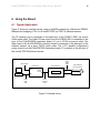
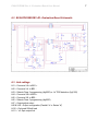
Silvertel
EVALPOE30W Rev 4
Evaluation Board User
Manual
Rev 4.0 – April 2012
EVALPOE30W Rev 4 - Evaluation Board User Manual
1
1 Table of Contents
1 2 3 4 Table of Contents
1 Table of Figures
1 Introduction
2 Board Description
2 4.1 Input Selection and Classification........................................................................ 2 4.2 PD Output Selection ............................................................................................ 4 4.3 Output adjustment ............................................................................................... 4 4.4 Minimum Load ..................................................................................................... 5 5 Typical Set-up
5 6 Using the Board
6 6.1 Typical Application .............................................................................................. 6 6.2 EVALPOE30W REV 4R - Evaluation Board Schematic ...................................... 7 6.3 Link settings ........................................................................................................ 7 2 Table of Figures
Figure 1: Board Layout .................................................................................................... 3 Figure 2: Basic set-up ..................................................................................................... 5 Figure 3: Example set-up ................................................................................................ 6 EVALPOE30W Rev 4 - Evaluation Board User Manual
3
2
Introduction
This manual is intended to be a guide to using the “EVALPOE30W Rev 4R” evaluation
board with Silvertel Powered Device (PD) modules.
The EVALPOE30W evaluation board can be powered using the spare pair in the CAT5e
cable (pins 4 & 5 and pins 7 & 8), or over the data pair through on-board magnetics.
4 Board Description
The EVALPOE30W Rev 4R evaluation board will work with the following products: Ag5000
Ag5100
The input data and power is supplied to the board through connector J1. The data is
passed through to the peripheral equipment via J2, with the power form the PD module
is supplied via J3 to J7 (see Figure 1 & 4).
The EVALPOE30W on-board bridge rectifiers will ensure that the correct input polarity
is applied to the PD.
When using the Ag5000, there are two LED’s (LED1 and LED2) that indicates which
input is applying the power (the silk screen on the PCB shows which pair SPARE or
DATA). Because the Ag5100 has a common input, when the main power is applied from
the PSE both LED will be ON.
Before using the EVALPOE30W evaluation board, it is important to setup the input and
output configuration jumpers for the product that is going to be use.
4.1 Input Selection and Classification
Links LK3 and LK6 (see Figure 1) are used to setup the input configurations for each
module.
EVALPOE30W Rev 4 - Evaluation Board User Manual
3
Ag5000 - For Class 3 programming, LK3 should be fitted between the “b” and centre
pins, LK6 should be fitted, for Class 0 remove both links.
Ag5100 - LK3 should be fitted between the “a” and centre pins, LK6 should be removed.
The Ag5100 is internally set to Class 4, when an IEEE802.3at PSE is connected to J1,
the PSE should recognize this and apply a two event classification. If the classification
conforms to the specification, the Ag5100 will recognize this and LED5 will turn ON.
Non IEEE802.3at compliant PSE (including IEEE802.3af PSE’s) will only apply a single
event classification and LED5 will remain OFF.
Figure 1: Board Layout
LK1, LK2, LK4 and LK5 are in series with each input pin, these links can be removed if
you need to measure the input current (see Figure 4 for more information).
EVALPOE30W Rev 4 - Evaluation Board User Manual
4
4.2 PD Output Selection
Both the Ag5000 and Ag5100 have two DC outputs that must be connected in parallel
or in series, the EVALPOE30W board output connections are shown in Table 1: Output
0V 1
VOUT 1
0V 2
VOUT 2
Connections
J6
J5
J4
J3
J7 (Outer)
J7 (Centre)
Table 1: Output Connections
The outputs cannot be run independently so the EVALPOE30W board has output
selector links LK8 and LK9. For parallel outputs both of these links must be in position
“a” - VOUT1 connected to VOUT 2 and 0V 1 connected to 0V 2. For series outputs both
links must be in position “b” – VOUT 1 connected to 0V 2.
The DC10 connector J7 delivers a nominal 12V when the outputs are in parallel and
24V when the outputs are in series (see Table 1 for connections).
4.3 Output adjustment
The primary output (VOUT 1 – 0V 1) has an ADJ pin, which allows the output voltage to
be increased or decreased from its nominal value. The secondary output (VOUT 2 – 0V
2) will track the adjusted primary output voltage.
The EVALPOE30W board has an adjust link LK7 and two resistors R9 (100K) and R10
(0R) which allows the output to be adjusted to its maximum and (Ag5100) minimum
values.
To reduce the output voltage (to its minimum) connect a link to LK7 position “a”, to
increase the output voltage (to its maximum) connect a link in position “b”. If the output
voltage needs to be set to a different value (within the adjustment range) then connect a
resistor instead of a (0R) link.
EVALPOE30W Rev 4 - Evaluation Board User Manual
5
4.4 Minimum Load
The PD module requires a minimum load of 200mA to maintain normal operation. The
EVALPOE30W board if fitted with a 200mA load which can be applied by fitting LK10. If
the external load connected to the board always exceeds 200mA, then this link does not
need to be fitted.
5
Typical Set-up
Figure 2 shows the basic set up using the POE evaluation board with a High Power
Midspan or Endspan.
The equipment required: ¾
¾
¾
¾
¾
Midspan or Endspan PSE (Power Sourcing Equipment)
Peripheral (or Test) Equipment
CAT5e cables
Output power cable
Mains cable
Mains Supply
Midspan / Endspan
POE Eval Board
Data & Power
PC or Switch
Data
Peripheral Equipment
J2
J1
J3 – J7
Figure 2: Basic set-up
Data
Power
EVALPOE30W Rev 4 - Evaluation Board User Manual
6
6 Using the Board
6.1 Typical Application
Figure 3 shows an example set-up using an Ag5000 powered by a Microsemi PD8001
Midspan and supplying +12V to a Vivotek PZ6122 (or PZ6112) ethernet camera.
The PC ethernet port is connected to the data input of the PD8001 (PSE) via a short
Cat5e patch cable. The Data & Power output from the POE30U-560 is connected to the
input of the EVALPOE30W evaluation board (J1) via a CAT5e crossover cable. The
data output of the EVALPOE30W evaluation board is connected to the data port of the
ethernet camera via a short CAT5e patch cable. The +12V (parallel configuration)
power output from the EVALPOE30W evaluation board (J7) connects to the dc input of
the Vivotek PZ6122 ethernet camera.
CAT5e
Patch
Cable
Mains Supply
EVALPOE30W
POE30U-560
J2
Mains
Data &
Power
PC
J1
Ag5000
Data
CAT5e
Patch
Cable
CAT5e
Crossover
Cable
Figure 3: Example set-up
J7
Data
+12V
Vivotek PZ6122
Ethernet Camera
EVALPOE30W Rev 4 - Evaluation Board User Manual
6.2 EVALPOE30W REV 4R - Evaluation Board Schematic
6.3 Link settings
LK1 – Connects VA+ to BR1 +
LK2 – Connects VA- to BR1 LK3 – Selects Class 3 programming (Ag5000) or “at” PSE detection (Ag5100)
LK4 – Connects VB+ to BR2 +
LK5 – Connects VB- to BR2 LK6 – Selects Class 3 programming (Ag5000)
LK7 – Output adjust select
LK8 & LK9 – Output configuration (Parallel “a” or Series “b”)
LK10 – On-board 200mA load
LK11 – “at” Opto output link
7