1
EVALPOE30W Rev 4 - Evaluation Board User Manual
3
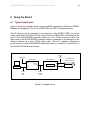
Ag5000 - For Class 3 programming, LK3 should be fitted between the “b” and centre
pins, LK6 should be fitted, for Class 0 remove both links.
Ag5100 - LK3 should be fitted between the “a” and centre pins, LK6 should be removed.
The Ag5100 is internally set to Class 4, when an IEEE802.3at PSE is connected to J1,
the PSE should recognize this and apply a two event classification. If the classification
conforms to the specification, the Ag5100 will recognize this and LED5 will turn ON.
Non IEEE802.3at compliant PSE (including IEEE802.3af PSE’s) will only apply a single
event classification and LED5 will remain OFF.
Figure 1: Board Layout
LK1, LK2, LK4 and LK5 are in series with each input pin, these links can be removed if
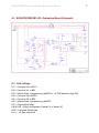
you need to measure the input current (see Figure 4 for more information).