1
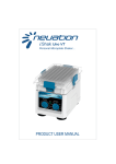
Shak BL Uno VT Personal Microplate Shaker... CONTENTS 1. Introduction.....................................................................1 2. Intended Use....................................................................1 3. Features........................................................................... 1 4. Technical Specification.....................................................2 5. Accessories...................................................................... 2 6. Types of Clamps............................................................... 3 7. Installation....................................................................... 4 8. Installing plate using O - Ring.......................................... 7 9. Installing Foam.................................................................8 10. Operation.......................................................................9 11. Tips for Efficient Operation..........................................10 12. Remote Operation.......................................................11 13. Safety Precautions.......................................................16 14. Warranty Statement.................................................... 17 15. Product Disposal..........................................................19 1.INTRODUCTION The compact personal microplate shaker is designed for accurate & even mixing of samples in a microplate. It is optimized to accept all standard plates and its 2.0 mm orbital motion allows thorough mixing across each well. The speed can be set from 300 to 1800 rpm. 2.INTENDEDUSE Personal Microplate Shaker is used for mixing liquids in a microtube. It can be used in areas of biochemistry, medicine, biotechnology and microbiology laboratories research. 3.FETAURES Exceptionally small footprint Uniformly shakes the microplate Accepts all standard microplates Replaceable clamps to hold different microplates Simple tool free clamp replacement Adjustable speed from 300 to 1800 RPM Anti-spill operation even at higher speeds Rubber suction cups for firm grip & stable operation Adjustable time from 1 to 99 minutes & continuous mode Model with USB Mode USB port for remote terminal control capability Remote operation with data logger 1 4.TECHNICALSPECIFICATION Orbital Motion Maximum Speed Variable Speed Run Time Maximum Volume LED Indicator 2.0 mm Diameter Orbital motion 1800 RPM 300 RPM to 1800 RPM 1 min to 99 mins & continuous mode 384 x 60 μl Power ON LED indicator 1.4 Kg Weight Dimensions (L x W x H) Power Supply 127 x 85 x 86 (mm) 100 - 240 VAC, 50 - 60 Hz Power Requirement 15 W 5.ACCESSORIES 1. Replaceable clamps and O - Rings 2. Alternate clamps & extra adjustable clamp 3. Power adaptor 4. Product user manual & warranty card 5. USB Cable (for USB mode) 2 6.TYPESOFCLAMPS Three types of clamps are provided with personal microplate shaker. Type - A clamp (Universal Clamp), Type - B clamp & Adjustable clamp as shown in the below figure. Type - A clamps & Adjustable clamp are preinstalled and Type - B clamps are with accessories. Type - A (Fix Universal Clamp) Type - B (Fix Clamp) Adjustable Clamp USINGDIFFERENTTYPESOFCLAMPS 1. Type - A Clamps are universal clamps and are use for most standard plates. 2. Type - B Clamps are use for larger microplates which contains outside ribs. 3. Adjustable Clamp are use to place microplate easily and lock it after placing it. 3 7.INSTALLATION Gently take the shaker out from packaging box and place it on the flat and non slippery surface. Do not lift the shaker by the shaking platform. Check that the rubber suction cup attached to the table well. Plug in the power adaptor pin before connecting to power source. The instruction manual and accessories should be kept with the device and please keep all the packaging in safe storage for atleast 2 years for warranty purpose. The standard clamps are pre-installed and a set of alternate clamps are supplied with the unit. In case to remove or replace the clamps, gently pull the clamps up after unlocking to remove and push down in the grooves to fix it again. Fix Universal Clamps Fix Universal Clamps Adjustable Clamp Adjustable Clamp g kin loc Un ck Ba Removing Clamps e e Sid ck Ba Sid Installing Clamps Note: The front side of the shaker contain speed & time knobs and back side contains power switch & power ports. USB port is available in model with USB. A special adjustable clamp is provided on the back side. 4 7.INSTALLATION Now to place the microplate on the shaking platform between 4 clamps, gently open the adjustable clamp to 90° as shown in the below figure. Microplate cannot be placed/attached properly to shaker if clamps are not fitted to it. Rotate 90° BaFc rkonSit dSeide Bac k Si de Opening Adjustable Clamp After opening the adjustable clamp to 90°, place the microplate as shown in the next figure. Gently pull the microplate inside and lock the clamp by turning 90° to firmly tight the microplate on shaking platform. Note: The front side of the shaker contain speed & time knobs and back side contains power switch & power ports. USB port is available in model with USB. A special adjustable clamp is provided on the back side. 5 7.INSTALLATION ide tS on Fr Installing Microplate Rotate 90° lockin g Bac k Si de Bac k Si de Locking Clamp to firmly tight microplate Note: We recommend to place the adjustable clamp on the back side of shaker. 6 8.INSTALLINGPLATEUSINGO-RING After placing or attaching the microplate between 4 clamps, if microplate is not attached firmly or it moves on the shaking platform during operation, then to attach microplate firmly, O-Rings are needed to attach first. Below figure shows that microplate is not attached firmly. Now take out the O-Rings from the packaging box and attach it on the clamps as shown in below figure. 2 - O-Rings Attach as shown above Stretch O-Ring Attach on 2 vertical side as shown in figure 7 9.INSTALLINGFOAM Shaker Foam is use to shake samples using microtubes. It supports all standard microtubes and have the capacity of 20 microtubes. Tips for efficient operation The basic requirement to ensure a fast and efficient mixing result is the generation of vortex which allows to produce a flow of the total sample volume. Based on the density of the samples, speed of the shaker and volume should be maintain. Hence, Ideally larger volume should be mixed with a higher orbit and low speed. Smaller volume requires a lower orbit, but a much higher speed. Please see the below image to learn how to attach the shaker foam in the shaker platform. O-Ring Foam Placing foam on shaking platform The above image shows the image of Foam. Place this Foam on the shaking platform and use O-Ring to attach the foam. Tight the Foam by pushing the O-Ring on the back side of the champs as shown in above figure. Once the Foam is attached, place the microtubes for shaking. Note: Filling microtubes more than 60 % and shaking it at max speed can lead to spill. 8 10.OPERATION To start the operation, connect the power adaptor to adaptor port in the back side of the shaker. USB Port Power Switch Adaptor Port Back Side Front Side Before starting the shaker, set speed and time from the control panel given in front side of the shaker. Rotate speed knob to set speed and rotate time knob to set time. Speed value is shown in the multiple of Hundred (x100) & Time value in Minutes (Mins). For Example, speed display with 18 digit means 1800 RPM & Time display with 18 digit means 18 minutes. Speed value varies from 300 RPM to 1800 RPM and time value varies from 1 minute to 99 minutes plus continuous mode. Continuous mode is shown with the symbol “ “. After setting the required speed and time, start operation by turning ON the power switch from the back side. The power LED in front will glow as an indication that shaker is started. NOTE: One can change time & speed during operation. Operation starts with slow speed & steadily rise to set level. For remote operation, connect the USB cable to the back side of shaker. Once USB cable is connected, controls of shaker will be disabled & only the ON/OFF switch will function. To stop operation turns OFF the power switch from back side. NOTE: Remote operation is for the model having USB mode. 9 11.TIPSFOREFFICIENTOPERATION Orbital shaking is undoubtedly a simple way for mixing of assay components but simply putting the samples on a microplate doesn’t guarantee complete blending is reached after the mixing process. A wide variety of well microplates are commercially available. The basic requirement to ensure a fast and efficient mixing result is the generation of vortex which allows to produce a flow of the total sample volume. The adjustment of the optimal mixing speed for microplates is dependent on the size of the well and the filling volume. The below table is a short summary for recommended mixing speeds for different microplates. Mixing speeds (rpm) for different microplates depending on filling volume/well (%) Filling Volume in % 96 Standard well 96 Deep well 384 Standard well 50 % 1400 - 1800 RPM 800 - 1200 RPM 75 % 1200 - 1600 RPM 600 - 1000 RPM 1600 - 1800 RPM 1800 RPM Hence, Ideally larger volume should be mixed with a higher orbit and low speed. Smaller volume requires a lower orbit, but a much higher speed. Note: Overfilling of wells can lead to spillage. 10 12.REMOTEOPERATION For remote operation the shaker needs to be connected to a computer. 12.1SYSTEMREQUIREMENT For remote operation, the following are the minimum system requirement: 1. Windows 7 with i3 Processor or more and Windows XP Service Pack 3 2. Microsoft .NET framework 4 and Microsoft Office Excel 2007 or 2010. 12.2INSTALLINGSOFTWARE Software CD is provided with the shaker kit. Install the software by running the setup file. The software Installation guide is provided in the software CD. After installation, software icon will appear on the desktop. 12.3CONNECTINGUSBCABLE Connect one side of USB cable to the back side of shaker and another side to computer USB port. NOTE: Remote operation is for the model having USB mode. 11 12.REMOTEOPERATION 12.4UNDERSTANDING&OPERATINGGUI After installing the GUI software, open GUI software by double clicking the software icon. The following GUI window will open on the computer screen. 12.4.1COMPORTCONNECTINGANDDISCONNECTING Once you connect the USB cable, the COM PORT for the shaker is detected automatically. Now click on the CONNECT button to connect shaker and computer for remote operation. After connection, the TEXT BOX will show “COM, iShak Connected”. Note: If any other device is connected after connecting Shaker then the COM PORT of software gets update. So, Select the shaker COM PORT from the COM PORT drop down box and click connect to reconnect the shaker. 12 12.REMOTEOPERATION The following change of image will appear in GUI screen. 12.4.2PRESETPROGRAMSELECTION Depending on the number of wells and total volume every microplate requires specific speed and time value for proper and anti-spill mixing. The GUI offers pre-defined shaking speed and time for the 3 common microplate use in this shaker. Select the pre-set program of specific microplate and then click on the start button to start operation. 12.4.3OPERATINGTHESHAKER To operate the shaker set the speed and time, then click on the START button to start operation. To stop operation, click on the STOP button. 13 12.REMOTEOPERATION 12.4.4SETTINGPROGRAMANDITSSELECTION User can save upto 4 user defined programs. To set program, click on the speed and time up/down scroll button of specific program and set the desired value. After setting desired speed and time value, click on the SAVE button to save the programs. To start the operation as per set program, click on the specific program button and then click on the start button to start the operation. 12.4.5PROGRAMSAMPLENOTEANDDETAILS User can write the details of sample used for shaking for their reference. User can also write any other specific information which is worth mentioning according to user. The data entered here will save in the data logger file for future reference. Click on the CLEAR button to clear the sample note and details. 14 12.REMOTEOPERATION 12.5DATALOGGER The remote operation comes with data logger features. All operations performed through the GUI will be saved in a excel sheet. With the help of data logger user can view and take a print out of previously performed operation. User can access the data logger file from the desktop. The data logger file will generate automatically on desktop of user’s computer once operation is performed. The following type of operation details will saved in an excel sheet. NOTE: The GUI software will not operate if data logger file is open. Be sure to close the log sheet before remote operation. 15 13.SAFETYPRECAUTION 1. Do not lift the shaker by holding the microplate or shaking platform. 2. Unplug the power adaptor before cleaning. 3. Always operate the unit on a leveled & stable surface to avoid any kind of accident. 4. Spill if it occurs, it should be removed promptly. Do not immerse the unit in liquid for cleaning. 5. The shaker can be cleaned with a damped cloth using water or m i l d detergents (after unplugging). Keep the unit clean for long life. Do not use shaker in hazardous atmosphere or with hazardous material for which the unit is not designed. 6. Do not operate the unit if it shows signs of electrical or mechanical damage. 7. The equipment will restart, both in case of mains interruption and in the case of any fault or mechanical interruption. So the care should be taken based on the sample used for mixing. 16 14.WARRANTYSTATEMENT This products is warranted to be free from defects in material and workmanship for a period of two (2) years from date of purchase. Your product will be duly repaired upon prompt notification in compliance with the following conditions : This warranty is valid only if the product is used for its intended purpose and within the guidelines specified in this instruction manual. This warranty does not cover damage caused by accident, neglect, misuse, improper service, natural forces or other causes not arising from defects in original material or workmanship. This warranty does not cover any incidental or consequential damages, commercial loss or any other damages from the use of this product. The warranty is invalidated by any non-factory modification, which will immediately terminate all liabilities on us for the products or damages caused by its use. The buyer and its customer shall be responsible for the product or use of products as well as any supervision required for safety. If requested the products must be returned to the distributor in well packed and insured manner and all shipping charges must be paid. Some states do not allow limitation on the length of implied warranties or the exclusion or limitation of incidental or consequential damages. This warranty gives you specific legal rights. This warranty is given expressly in lieu of all other warranties, expressed or implied. 17 14.WARRANTYSTATEMENT The purchaser agrees that there is no warranty of merchantability or of fitness for any intended purpose and that there are no other remedies or warranties, expressed or implied, which extend beyond the description on the face of the agreement. This warranty is only applicable to the original purchaser. The software is made available with the kit. It is designed to work on Windows XP SP3, Windows 7. The software should be used as explained in the user manual. The warranty does not cover the software failures due to issues in user system (computer or laptop). Products received without proper authorization will not be entertained. All items returned for service should be sent postage prepaid in the original packaging or other suitable carton, padded to avoid damage. We will not be responsible for damage incurred by improper packaging. All items returned for service should be set postage prepaid in the original packaging or other suitable carton, added to avoid damage. This warranty is valid only if the warranty is registered with the supplier within 30 days from the date of purchase. 18 15.PRODUCTDISPOSAL In case the product is to be disposed of, the relevant legal regulations are to be observed. Information on the disposal of electrical and electronic devices in the European Community The disposal of electrical devices is regulated within the European Community by national regulations based on EU Directive 2012/19/EU on waste electrical and electronic equipment (WEEE). According to these regulations, any devices supplied after 13.06.05 in the business to business sphere, to which this product is assigned, may no longer be disposed off in municipal or domestic waste. They are marked with the following symbol to indicate this. As disposal regulations within the EU may vary from country to country, please contact your supplier if necessary. 19