1
Wearable Honeypot
Presented as a record of progress in this MQP to
Professor Krishna Venkatasubramanian
Professor Thomas Eisenbarth
By,
Mudassir Ali
Acknowledgment
For a project that is extremely different and new to me, I believe I learned a lot because
of my partner, Andrew Leonard. His presence in this project was a great benefit to me in many
different aspects. The time and effort Andrew spent explaining and guiding me through this
project is something that I am very thankful and grateful for. His help gave me the necessary
background needed to understand some choices that were made in this project. Without his
support, I would not be able to keep up with everyone else on this team. Aside from the project,
I also learned a lot from Andrew himself. Our long nights were not just spent working on this
project but also utilized to expand my knowledge and understanding in the Computer Science
field. I would like to thank Andrew for being a great teacher, a fantastic partner and most
importantly, a great friend.
2
Abstract
Wearable embedded devices are in common use in the medical industry. In today’s
society security is needed in just about every electronic device. However, these devices don't yet
have many security standards. To prevent scenarios that involve unauthorized sources intruding
on a device, a honeypot could be used as a secure lightweight (in terms of resource usage)
addition to these medical devices. Honeypots typically have a monitoring component, this allows
a system designer to gain knowledge of exploits which can then be patched. This project seeks to
devise and implement a wearable honeypot to add security to a BAN (Body Area Network).
3
Table of Contents
Acknowledgment .......................................................................................................................................... 2
Abstract ......................................................................................................................................................... 3
Table of Figures ............................................................................................................................................. 5
Table of Tables .............................................................................................................................................. 5
1 Introduction ............................................................................................................................................... 6
2 Background ................................................................................................................................................ 7
2.1 Bluetooth ............................................................................................................................................ 8
2.2 Honeypots ........................................................................................................................................... 8
2.2.1 Honeypot Classification ............................................................................................................... 8
3 Related Works ............................................................................................................................................ 9
3.1 HoneyDroid ....................................................................................................................................... 10
3.2 HoneyDroid Extension ...................................................................................................................... 12
3.3 Mobile Honeynet .............................................................................................................................. 13
3.4 Mobile Communication Honeypot.................................................................................................... 14
4 Problem Statement .................................................................................................................................. 14
5 Motivations .............................................................................................................................................. 15
6 System Model .......................................................................................................................................... 15
6.1 BAN.................................................................................................................................................... 15
6.2 Threat Model..................................................................................................................................... 18
7 Wearable Honeypot ................................................................................................................................. 18
7.1 Message Mode .................................................................................................................................. 19
7.1.1 Synthesizing Accelerometer Data .............................................................................................. 21
7.1.2 Message Window ........................................................................................................................... 28
7.2 Honeypot Detection Mechanisms .................................................................................................... 30
7.2.1 Bluetooth & Disconnection Attacks ........................................................................................... 31
7.2.3 Targeting BS by Spoofing Motes ................................................................................................ 32
7.2.4 Spoofing Basestation to Target Motes....................................................................................... 37
8 Conclusion ................................................................................................................................................ 39
9 Future Works ........................................................................................................................................... 40
10 References ............................................................................................................................................. 40
Appendix ..................................................................................................................................................... 44
A.1 Bluetooth Background Info ............................................................................................................... 44
A.1.1 Device ID .................................................................................................................................... 44
A.1.2 Pairing ........................................................................................................................................ 44
A.1.3 Frequency Hopping .................................................................................................................... 45
A.1.4 Bluetooth Stack.......................................................................................................................... 45
A.1.5 Bluetooth Security ..................................................................................................................... 46
A.2 Development Issues .......................................................................................................................... 47
A.2.1 Issues with Banmqp implementation ........................................................................................ 47
A.2.2 Development Issues................................................................................................................... 48
A.2.3 Development Best Practices ...................................................................................................... 48
A.3 PRNGs ............................................................................................................................................... 49
A.3.1 RC4 ............................................................................................................................................. 49
A.3.2 Mersenne Twister ...................................................................................................................... 50
A.3.3 TinyMT ....................................................................................................................................... 51
4
Table of Figures
Figure 1: Wireless BAN................................................................................................................................ 6
Figure 2: Classification of Honeypots ........................................................................................................ 10
Figure 3: Design of HoneyDroid ................................................................................................................ 11
Figure 4: HoneyDroid Extension ................................................................................................................ 12
Figure 5: Mobile Communication Honeypot .............................................................................................. 14
Figure 6: Types of Messages in BAN Protocol .......................................................................................... 17
Figure 7: BAN Wearable Honeypot Overview ........................................................................................... 17
Figure 8: Wearable Honeypot Architecture ............................................................................................... 19
Figure 9: Original Walking Accelerometer Data ........................................................................................ 22
Figure 10: Original Standing Up From Sitting Accelerometer Data .......................................................... 22
Figure 11: Original Sitting Accelerometer Data ......................................................................................... 23
Figure 12: Original Sitting Down Accelerometer Data .............................................................................. 23
Figure 13- Modified Walking Accelerometer Data .................................................................................... 26
Figure 14: Modified Standing Up Form Sitting Accelerometer Data ......................................................... 26
Figure 15: Modified Sitting Accelerometer Data........................................................................................ 27
Figure 16: Accelerometer Data Compared With Randomized Data ........................................................... 27
Figure 17: Disconnection Attack ................................................................................................................ 31
Figure 18: Spoofed Mote Attacks ............................................................................................................... 33
Figure 19: Spoofed Base Station Attacks ................................................................................................... 37
Figure 20: Bluetooth Pairing Process.......................................................................................................... 44
Figure 21: Bluetooth Protocol Stack ........................................................................................................... 46
Table of Tables
Table 1: Honeypot Message Mode Specification ....................................................................................... 20
Table 2: Standard Diviation ........................................................................................................................ 23
Table 3: PRNG Operation Comparison Table ............................................................................................ 24
Table 4: Bluetooth and Disconnection Attacks........................................................................................... 31
Table 5: Spoofing Motes Already In Ban ................................................................................................... 33
Table 6: Spoofed Base Station Attacks ....................................................................................................... 37
5
1 Introduction
In this modern information age, wearable embedded devices (small sensors with
microcontrollers equipped with wireless communication) have become common use in the
medical industry [10]. More recently a consumer market has developed for these kinds of
devices [9]. Wearable embedded devices connected to a base station form a piconet (small
network) called a BAN (Body Area Network AKA Body Sensor Network). Currently, most
implementaions of BANs are used by the medical industry because by attaching multiple sensors
to someone, different medical stats can be gathered and then analyzed by a doctor in the
treatment of a patient [1]. With the advent of products such as the Apple Watch, BANs are
moving into broader consumer use. With small sensors, the user can usually maintain a normal
lifestyle even with all the monitoring. A BAN is shown below in Figure 1.
Node 3
Node 1
Node 2
Node 3
base station
Node 5
Figure 1: Wireless BAN
6
Our work is built on a Bluetooth-based BAN system built on the Shimmer platform, and
utilizes a BAN-PnP application-layer protocol [19]. The BAN has a basestation implemented as
an Android app; the motes (node on sensor network) on the sensor network are Shimmer motes
[1]. The BAN itself already provides a measurable hit to the performance of the motes [1]. This
illustrates the need for lightweight security protocols. This BAN is ideal for our purposes as it is
cross platform. It only requires a device to implement the BAN protocol on top of Bluetooth.
Most importantly this BAN is plug 'n play and base station firmware does not need to be updated
to accommodate new motes with previously unknown functionality [1]. Generally, these wireless
devices are short ranged, however this does not shield users from attackers.
Today security is needed in just about every electronic device, however BAN devices
don't yet have many security standards. To prevent unauthorized sources from intruding on a
device, a honeypot could be used as a lightweight addition to these medical devices. Honeypots
typically have a monitoring component. This allows a system designer to log and recreate
exploits so that they can be patched [15]. Most of the time, when no threats are present, the
honeypot requires little computation and therefore doesn’t use much battery power. Additionally,
when a threat is detected heavier weight security measures (i.e. thorough packet sniffing and
analysis) can be activated [14]. These heavier weight security measures would produce a
significant drain on battery power if they were always active. This project seeks to devise and
implement a wearable honeypot to add security to a BAN. Previous honeypots are mostly used in
enterprise environments. Recently, there have been groups working on mobile honeypots, which
are essentially mobile versions of enterprise honeypots. Our honeypot will be a new application,
however many design principles will remain the same as traditional honeypots.
In the honeypot for the sensor motes the Shimmer Platform will be used. For the motes
TinyOS is used "because it’s been around so long, the code has been well tested, and a strong
community has had the time to build up. With a better community comes better support and by
extension an easier time solving problems that will arise in development” [1]. For the base
station we are using an app on an Android based phone as this would likely be an item a patient
needing a BAN might have.
2 Background
To understand this project, a basic understanding of Bluetooth and honeypots is required.
Bluetooth is used as the means of communication within a BAN and operates at similar
7
frequencies to Wi-Fi [27]. This project aims to design a honeypot to detect attacks on a BAN,
which can be used to improve the security of the BAN.
2.1 Bluetooth
Bluetooth is a peer to peer communication protocol over a short range broadcast medium.
In a Bluetooth piconet there is one master and up to 7 slaves. The master initiates activities and
slaves respond to the master. To add a slave to the piconet a master must initiate pairing with a
slave. When communicating, the master hops between 7 channels and the slaves hop between
another 7 channels to send packets. Bluetooth operates in the 2.4-2.485 GHz data range [26].
Like TCP/IP, it has a stack to abstract out the hardware from the application programmer.
Bluetooth is also widely used, despite known vulnerabilities and demonstrated hacks [22].
2.2 Honeypots
A honeypot is best understood as a trap for attackers [14]. A honeypot is a system whose
main purpose is to be attacked and compromised [5]. They monitor what goes in and what goes
out of a system and are isolated, sometimes even running on a separate device. Some honeypots
act as a decoy server that tries to compromise the attack and make themselves easy targets [16].
Honeypots can log all the incoming and outgoing packets so any vulnerability can be looked
back on and analyzed for future study. There are scenarios where multiple different honeypots
are used within a system. This is referred to as a honeynet [13].
There are many advantages to a honeypot. One advantage is that a honeypot can record
illegitimate activity. They are usually encrypted environments, and don’t require known attack
signatures [15]. But like all things, the honeypot has some disadvantages too. For instance, there
are some types of honeypots that can be used to attack other systems. Also, a honeypot cannot
detect if other systems are being attacked. It only knows what is going in and out of its own
system. A honeypot may also be detected by the attacker.
2.2.1 Honeypot Classification
While there are different applications and implementations of honeypots, they fall into a
couple archetypes based upon purpose and implementation. Usually they’re either passive or
active. Passive honeypots collect data for analysis so exploits can become known and patched.
Active honeypots detect threats and then do something in response. Honeypots are usually high
interaction or low interaction. Low interaction honeypots recreate small subsets of a system, are
8
generally simple, and not resource intensive. High interaction honeypots recreate entire
subsystems resulting in higher security at the expense of maintenance costs. The extreme case of
a high interaction honeypot would be a pure honeypot. In a pure honeypot the entire system is a
honeypot, not a mix of simulated subsystems. In terms of purpose, there are two main types of
classification, enterprise and research honeypots. Research honeypots are typically passive
honeypots that collect extensive information about hacks and exploits and are generally used for
research, hence the name. The other kind is an enterprise honeypot. Typically enterprise
honeypots are low interaction, or made with multiple low interaction implementations. This is
for practicality purposes because they are easier to deploy and maintain. After all they are made
for production environments.
3 Related Works
Examples of enterprise Honeypots are Google Honeypot, Honeyd, Homemade honeypot,
ManTrap and BackOfficer Friendly [13]. The following infographic in Figure 6 visualizes our
taxonomy and classification of well-known honeypots and the mobile honeypots discussed in
Figure 2. Some of the mobile honeypots are in the early stages of design and therefore we
9
couldn’t thoroughly classify all of them...
Figure 2: Classification of Honeypots
3.1 HoneyDroid
One example of a mobile honeypot is the HoneyDroid [5]. This honeypot system deals
with 4 challenges: monitoring, audit logging, containment and visibility. The monitoring issue
involved how to monitor everything occurring in the system without causing the OS to be easily
compromised [5]. The goal in monitoring is to have a system that can monitor everything such
that they can recreate the exact event. The audit logging issue is about creating a secure, reliable
storage compartment of all the logs. In containment, the honeypot has to be designed such that
the attacker is able to easily stumble into it but becomes trapped in the honeypot and isn’t able to
make any further attacks [5]. The issue with visibility is that the honeypot needs to be exposed
enough so that the attacker can attack it, but not so visible that it's obvious and easy to get around
[5]. The design of the HoneyDroid is shown below in Figure 3:
10
Figure 3: Design of HoneyDroid
In this diagram the Event Monitor is placed in between the Android OS and Android’s
own form of Event Monitor that monitors calls and signals. In HoneyDroid the Android OS is
not able to have direct access to the hardware. Instead, HoneyDroid virtualizes everything thus
allowing everything to be monitored. This also allows them to take snapshots of the system. In
this system, the Android OS has no access to the snapshots either; the virtual modem is used to
fight against malware, leading to the containment functionality [5].
The log component receives information from different areas of the system. These logs
ensure integrity through time stamps. [5]. For visibility, this honeypot is given a public IP
address. It is planned for HoneyDroid to have automatic installation and execution privileges,
and give the honeypot access to the internet and allow the honeypot to spread the google account
name associated with the honeypot. [5].
HoneyDroid seems to be a great system to reference our honeypot. Monitoring, audit
logging, containment and visibility are key components needed for our specific system.
Specifications of where certain components are stationed may alter however the idea of time
stamping all components that enter and leave the honeypot, the ability to snapshot system
11
activities and the honeypot given a public IP all seems promising for our honeypot system.
However, while this honeypot contains many useful properties, it simply doesn't provide security
to Bluetooth.
3.2 HoneyDroid Extension
Extending from the HoneyDroid, lack of behavioral considerations and existing security
policy on the mobile device platform became additional challenges. The lack of behavioral
considerations means mobile users desire to give up security in return for free access to
applications. This means it’s hard to take into account user actions such as rooting their phones
or installing malicious applications. The second challenge involved how certain Android
functions limited the honeypot functionality. These Android functions include things that are
able to bypass the Android security such as SMS and MMS [4]. Figure 4 bellow illustrates the
framework for this mobile honeypot.
Figure 4: HoneyDroid Extension
In this scenario, this mobile honeypot is intended for threats coming from data networks
that are connected telecommunication cells [4]. The connection for the smart mobile honeypots
comes through from telecommunication stations, Wi-Fi and Bluetooth. The smart mobile
honeypots have 2 states: state 1 records data and connects to web server to send this data; state 2
involves threat monitoring, audit logging, containment and modeling functionalities.
State 1 has a honeypot that communicates with other honeypots. Specifically when data
is being sent from the device, it goes through a honeypot which communicates with other servers
with honeypots. Then when data is being sent back the honeypot records everything coming in
[4]. State 2 is a software implementation of threat monitoring, audit logging, containment and
user’s behavioral logging requirements. Thread monitoring is responsible for monitoring data
packets going in and out of the system. When a threat is detected, it will gather data focused
around that attack. The audit logging will be a copy of the gathered data and will be backed up
on another server. For containment, the honeypot will isolate the attack and not let it continue on
through the network. If there was an occurrence of a fast speeding threat, the mobile device will
12
be cut off from the network. Another module called User Behavioral Module will be monitoring
and tracking the user’s patterns [4].
The additions to the HoneyDroid seem plausible. However, for the BAN honeypot it is
assumed the user is not interested in lowering its security and rooting their Android device.
Communicating with other honeypot devices for stronger security is also not in the scope of this
project. This idea may be used for future works but is not useful for the design of our BAN
honeypot.
3.3 Mobile Honeynet
The implementation of Mobile Honeynet was based on 3 main questions:
1) Is it necessary that the probe runs on a mobile device
2) Is it necessary that the honeypot runs on a mobile OS
3) To which network is the mobile honeypot connected
This system made the assumption that there is no need to have a mobile honeypot on a
smartphone [7]. Instead a Linux operating system was used for 2 reasons. One, most
smartphones use Android OS and, two, it allows you to reuse existing honeypot tools. [7]. To
answer the third question, the mobile probe should connect to a real mobile network. If not, there
is a chance the attacker can detect differences.
The implementation of this mobile honeypot consisted of three other honeypots: Kippo,
Glastopf and Dionaea. Kippo is an SSH honeypot that has a trivial password. This allows the
attacker to gain access into the system. The attacker is given administrator privileges where the
attacker can execute common programs, download and install anything else they wanted. In the
background the honeypot records everything and uses it later for analysis. To prevent more
problems for the honeypot, executing newly installed programmers are prohibited.
The second honeypot, Glastopf provides uploads to web-based servers. This honeypot
monitors and watches this upload and logs everything that comes in and out of this uploaded file.
And finally, Dionaea is a honeypot that monitors all transport ports.
For our BAN honeypot, this honeynet system cannot be referenced. This honeynet system
regards the fact a mobile honeypot is needed and attempts to utilize other manufactured
honeypots. When implementing our own honeypot other manufactured honeypots cannot be
used.
13
3.4 Mobile Communication Honeypot
The final system had an interesting way of implementing their mobile honeypot. The
design is shown below in Figure 5. [7]
Figure 5: Mobile Communication Honeypot
As this figure shows the honeypot is broken down into four layers: access, networking
simulating wireless environment, data transmission, data analysis and system supervisor. Within
these layers mobile communication terminals, wireless link access module, data transmission
module and application processing center module [7].
This communication honeypot cannot be referenced when designing our BAN honeypot.
Even though this system is plausible, our BAN communicates through Bluetooth and does not
require the Internet.
4 Problem Statement
The challenge of this project is to develop an effective honeypot that doesn't greatly
diminish the performance of the devices in a BAN. Meanwhile it still must monitor effectively
14
enough to detect attacks on the BAN. Just running the BAN protocol has already affected mote
battery life [1]. The high level design goals of the Honeypot were as follows:
•
Obvious enough to be an attack target, but not obviously a honeypot.
•
Easily comprisable without allowing the BAN to be compromised.
•
Effectively detects attacks
•
Extensive logging with timestamps so attacks can be reconstructed from logs.
•
Shouldn’t be a large burden on the power requirements of the embedded sensors.
5 Motivations
Mobile honeypots are a new field and BAN honeypots don't yet exist. The basic
motivation behind this project is that wearable embedded devices do not have much security
[17]. Wearable embedded devices include modern pacemakers. Thus one of the chief
motivations of this project is to make these devices safe to use [14]. Wearable embedded devices
also have strict battery requirements meaning that any security measures would have to be
lightweight. In a passive state a honeypot doesn’t necessarily require a lot of computational
overhead. To make these devices safe in a practical way, the flexibility of a honeypot is
desirable; standard cryptographic routines are not desirable because they are computationally
expensive. Finally, there is a need to secure vital wearable embedded devices to be safe to use
and this will take more than just implementing standard security.
6 System Model
6.1 BAN
The system we are using is a plug and play BAN protocol. The BAN consists of a base
station (BS) and sensor nodes or motes. The BAN was designed as a link layer protocol with
these properties:
•
Does not inherently rely on static message identifiers,
•
Supports new sensors, motes, and commands without changes to the mote
firmware or base station application
15
•
Have a flexible base station learning language that can be expanded easily
through changes to a few Grammars and
•
Have a BAN platform that is flexible enough to support any type of research or
real world application.[1]
In creating this BAN protocol, a platform was needed. For a mobile device, the team
decided on the Android platform due to its wide usage across many different devices. For a
sensing platform, they decided on the Shimmer platform. Shimmer is designed specifically for
wearable applications and is used widely in medical fields. Much of Shimmer’s resources are
open source, making it useful to the goal of that protocol.
Shimmer’s sensors are separated into three groups including kinematic sensors,
biophysical sensors, and ambient sensors. Kinematic sensors record movement (i.e. velocity and
position), biomedical sensors record medical data (i.e. heart rate and body temperature), and
ambient sensors measure environmental properties (i.e. temperature and humidity). Shimmer
comes with the following sensor options: ECG, EMG, GSR, 9DoF, GPS, Strain Gauge, and
Accelerometer. Shimmer also includes LabView, Matlab, Android, and Windows applications as
base station platforms [12]. For the OS platform, Shimmer’s motes are TinyOS based. The
implementers of the BAN used TinyOS because it's a well-used library that's been around for a
long time and has a large support community [1].
The protocol itself is very good for generic use. The mote has six states: Idle,
Discoverable, Paired, Connected, Command & Inquiry and Streaming. The Base station, on the
other hand has a total of seven states: Idle, Discovery, Paired, Connected, Command & Inquiry,
Mote Data and Mote Response. As a general summary, the BAN is designed using a state
machine design pattern. Each state has one action. Some states allow a user to send commands,
request sensor data, receive sensor data, etc. Doing a different task means transitioning to a
different state. The protocol specifically forbids doing or requesting an action for a state other
than the one the mote is currently in [1]. The way this is implemented is through a set of
functions that allows the base station to ask each mote that connects how to use it. This allows
the motes to teach the base station all of its functionality. Thus, the base station has no prior
knowledge of what any of the motes can do. There are only 7 different kinds of messages in the
BAN protocol, they are detailed in Figure 6:
16
Figure 6: Types of Messages in BAN Protocol
This means that the BAN is completely extendable to include different motes without
updating the base station. The unused message types allow the protocol itself to be extended as
well. Figure 7 illustrates the communication architecture of the BAN.
Mote
Slave
Slave
Mote
Mote
Slave
Master
Normal BAN Communication
Figure 7: BAN Wearable Honeypot Overview
17
6.2 Threat Model
In addition to the protocol there are a few more assumptions. One assumption is that the
base station user is not the attacker as a BSN can contain important medical devices. The base
station can only pair with motes when the user initiates pairing. It is assumed that the user will
not knowingly pair with any attacker. In addition to the system here, we need to make
assumptions about an attacker.
There is an assumption that the attacker would have relatively high computational
abilities – in addition to the computational power of today's high end laptops it is relatively
cheap and simple to rent out compute time on servers from companies like Amazon. Specifically
Amazon Web Services has the Amazon Elastic Compute Cloud (Amazon EC2), which gives 750
computing hours on Linux and 750 hours on Windows server free then charges $0.105 (2 Cores
and 3.75 GiB RAM) to $1.68 an hour (32 cores and 60 GiB RAM) for compute time on compute
optimized servers [28]. The attacker can also spoof, launch man in the middle attacks, and has
the knowledge to decrypt encryption. With the short range of Bluetooth, we also assumed only
one adversary; however that one person can use multiple devices simulating multiple
adversaries.
7 Wearable Honeypot
The Wearable Honeypot system is meant to detect threats to a BSN. The basis for the
honeypot is a message mode. The message mode involves a message exchange between the BS
and specialized helper motes. The BS and the motes communicate in a pre-arranged way. This
message exchange acts as bait for an attacker to pay attention to the helper motes because it is
the most active part of the BAN. Initially just like with other motes, the base station will ask for
all information about the motes (sensors, types of data, commands, etc.) and then enter message
mode. In this mode the BS periodically sets and resets what the motes are sending to it. The data
the mote sends back is coordinated and known to the basestation. An attacker spoofing messages
would cause the expectations of this system to be violated. Using this approach many attacks can
be detected. The architecture of the honeypot is shown in Figure 8.
18
Figure 8: Wearable Honeypot Architecture
Because a honeypot is meant to detect threats, as a first step in designing the honeypot
system, a threat model was developed. The threat model was an outline of all possible adversary
attacks the honeypot will be on the lookout for. By examining the Bluetooth protocol and BAN
protocol, attacks were devised. This eventually became a honeypot model when corresponding
detection information was added. However, before that is presented, it is important to understand
message mode because the honeypot model depends on it.
7.1 Message Mode
As mentioned above, the detection mechanisms depend on a message coordination
scheme. There are two logical communication channels between the helper motes and the base
station, a high security channel and a low security channel. The high security channel is where
the message mode is coordinated by the basestation and the low security channel is for “normal”
BAN PnP communication. This message coordination scheme relies on simultaneously
synthesizing accelerometer data on the motes and BS, which involves a PRNG (Pseudo-random
Number Generator). Over the high security channel, the base station sends a coordination
message which tells the motes which kind of accelerometer data (sitting or walking) to
synthesize and how many data points to send back to the base station as supposed sensor data for
accelerometers. This way, the base station can know what messages to expect from motes and
19
when (these stream in and the average rate is monitored for sudden changes). Additionally, once
a mote receives a coordination message, it should only ever expect more of them and nothing
else. If a mote receives any other message it will send an encrypted message to the base station
indicating that an attacker was detected. If the base station receives any packets from helper
motes before they request data stream to be started, then this also allows attackers to be detected.
Table 1 presents packet description of the coordination message and an example mote return
packets. The base station coordination message packet is broken down into two parts: Header
and Body. The header specifies the packet size, sequence number and Message ID (1111 1110b).
The body specifies the type and the number of accelerometer values to send as well as initializes
the PRNG. The mote packet response also contains a header and body where the header
specifies packet size, sequence number and message ID while the body specifies Sensor ID and
message value.
Table 1: Honeypot Message Mode Specification
Honeypot Message Mode Specification
BS Coordination Message
// Header:
0000 0000
0001 1000 : packet size 24
0000 0000
0000 0111 : sequence number
1111 1110 : message ID
// Body
// 10 messages -- array of 10 16 bit values
0000 0001 : // Type of data, 1 for walking, 0 for sitting
0000 0010
1101 0000 : // Number of data points to send
// 4 32 bit integers to initialize PRNG
0000 0011
0100 0111
0101 0000
0101 0011 : 1
0000 0000
0110 0011
0111 0111
0010 1010 : 2
0011 1001
0110 0000
0000 0011
0110 0100 : 3
1010 0101
0111 0111
0111 1000
0000 0100 : 4
Example Mote "DATA" Response Packets
// First mote response
// Header:
0000 0000
0000 1000 : packet size 8
0000 0000
0000 1000 : sequence number
0000 0000 : message ID - mote data
// Body:
0000 0001 : Sensor ID
0110 0011
0100 0010 : Sensor data payload (message value)
// Second mote response
// Header:
0000 0000
0000 1000 : packet size 8
0000 0000
0000 1001 : sequence number
0000 0000 : message ID - mote data
// Body:
0000 0001 : Sensor ID
0110 0000
0000 0011: Sensor data payload (message value)
// Third mote response
// Header:
0000 0000
0000 1000 : packet size 8
0000 0000
0000 1010 : sequence number
0000 0000 : message ID - mote data
// Body:
0000 0001 : Sensor ID
0100 0111
0101 0000: Sensor data payload (message value)
20
In a situation where an attacker is detected, the message ID would alter to 1111 1101b and
transmit this sequence over the secure channel.
With this communication mechanism, the base station will know when it wasn't a
honeypot mote that sent the message. Additionally, the attacks themselves depend on a Python
library called Scapy [24]. Scapy is a packet manipulation program [24]. This Python library
supports Bluetooth frames and is ideal for our purposes because it makes spoofing simple. The
encryption of the application packets themselves uses the AES block cipher in the cipher block
chaining (CBC) mode.
7.1.1 Synthesizing Accelerometer Data
For the message mode, we needed to determine a method to send false yet realistic data
to attract the attacker’s attention yet not make it obviously fake. The idea we set upon was to
synthesize real sensor data. We settled on accelerometer data as the best option for this endeavor.
There are many devices with accelerometers and it isn’t abnormal for someone to have more
than one sensor monitoring accelerometer data. After that, exactly how we synthesize it became
the next issue. Mathematically synthesizing the data is very computationally intensive, so we
decided to start with a real data bank of accelerometer values for different activities.
7.1.1.1 Real Accelerometer Data
We found data collected and published for the purpose of activity recognition from
accelerometer data [29]. The activities were separated, graphed, and the standard deviations were
calculated in order to understand the data. Our honeypot is kept simple and uses two main
activities and two more as transitions between them. Walking and sitting are the main activities.
When transitioning from sitting to walking, one must first stand up from sitting, which we have
data for; when going from walking to sitting, one must sit down first. These provide a couple
seconds of realistic transition. There were more activities available (such as lying down, on all
fours and falling), however these activities that don’t generally happen in public. The graphs in
Figure 9 present the data points of the selected four activities.
21
Walking
5
X
Y
Z
4.5
Accelerometer Data
4
3.5
3
2.5
2
1.5
1
0.5
1
4
7
10
13
16
19
22
25
28
31
34
37
40
43
46
49
52
55
58
61
64
67
70
73
76
79
82
85
88
91
94
97
100
0
Number of Data Points
Figure 9: Original Walking Accelerometer Data
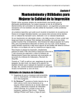
Figure 9 shows a fairly consistent data set of walking accelerometer values. Towards the
end it appears that the user may have been transitioning to another activity because it doesn’t
match the general pattern in the rest of the data. While calculating the standard deviation these
values were ignored.
4
Standing Up From Sitting
X
Y
Z
Accelerometer Data
3.5
3
2.5
2
1.5
1
0.5
0
-0.5
1 3 5 7 9 11 13 15 17 19 21 23 25 27 29 31 33 35 37 39 41 43 45 47 49 51 53 55 57 59 61 63 65 67 69 71 73
Number of Data Points
Figure 10: Original Standing Up From Sitting Accelerometer Data
Figure 10 shows accelerometer values for standing up from sitting. The data in this
section is fairly regular between points, however a little past halfway through there is a major
shift downward for the X and Y. From that point on it is fairly regular again. To accommodate
for this, the graph was divided in two and two different standard deviations were calculated.
22
X
Sitting
4
Y
Z
Accelerometer Data
3
2
1
1
4
7
10
13
16
19
22
25
28
31
34
37
40
43
46
49
52
55
58
61
64
67
70
73
76
79
82
85
88
91
94
97
100
0
-1
Number of Data Points
Figure 11: Original Sitting Accelerometer Data
Figure 11 shows the accelerometer data from sitting. As would be expected it is very regular.
Sitting Down
5
X
Y
Z
Accelerometer Data
4
3
2
1
1
4
7
10
13
16
19
22
25
28
31
34
37
40
43
46
49
52
55
58
61
64
67
70
73
76
79
82
85
88
91
94
97
100
0
-1
Number of Data Points
Figure 12: Original Sitting Down Accelerometer Data
Figure 12 shows the sitting down data. Due to the Y vector presenting a similar problem to
standing up from sitting down, all vectors were divided in two and two separate calculations
were made for both range and standard deviation. The smallest range and standard deviation
values for each vector were used for future calculations. Table 2 presents each activity’s vector
and their standard deviations.
Table 2: Standard Deviation
Activity
Walking
Vector
X
Standard Deviation
0.272615
23
Y
0.151893
Z
0.407375
Standing Up From Sitting
X
0.149059089
Y
0.109661235
Z
0.407219629
Sitting
X
0.185340687
Y
0.326012929
Z
0.450997835
Sitting Down
X
0.221174625
Y
0.363783609
Z
0.443966194
As one may notice, if we simply replay this data over and over, it would become obvious
that it is fake. There are some areas where data points are exaggerated. These would be most
obvious. However we interpreted those data values as noise when the test subject transitioned
from one activity to another. Using this assumption those values were ignored for the calculation
of the standard deviation for each dataset. However, even without the spikes, transmitting the
same values every 100 or so points will be obviously fake anyway. Therefore we need to modify
this data.
7.1.1.2 Pseudo-random Number Generator Selection
Initializing the PRNG requires determining a method to randomize the accelerometer
data. Several PRNG’s were researched; three in particular: RC4, Mersenne Twister and TinyMT.
Since the quality of randomness wasn’t as important as minimized computational load and
maximizing battery efficiency, first an analysis of the number of operations (assignment,
arithmetic operations, bitwise operations such as & and bitshift) required to generate random
numbers:
Table 3: PRNG Operation Comparison Table
Attribute
RC4 [31]
Mersenne Twister
[32]
2496 Bytes
TinyMT [30]
State Memory Size
256 Byte + 40 Byte
key
Operations until 1st
number
206 + 2844 = 3050
4364 + 8112 + 20 + 1
= 12478
101 + 41 = 142
Operations Until 2nd
Number
3050 + 2844 = 5894
12478 + 20 = 12498
142 + 41 = 183
16 bytes
24
Operations until Nth
number
206 + 2844N
+⌊(N/40)⌋*204
4364 + 8112 + 20N +
1 + ⌊(N/624)⌋*8112
101 + 41N
As you can see, the TinyMT PRNG is a clear choice given those criterion. Additionally it
is also of high quality. It has a period of 2127, and the floating point numbers are based upon
evenly distributed 32 bit integers [30]. Pseudo-code or implementations for each is included in
the appendix. Using TinyMT, we can add small random offsets to the original Data.
7.1.1.3 Modified Accelerometer Data
Utilizing the TinyMT PRNG as well as the calculated standard deviations of each
activity’s vector, multiple randomized number is tempered to within +- one standard deviation.
TinyMT can return a floating point r such that 0 <= r < 1. Equation 1 can be used to temper r to
the desired range.
𝑟𝑟` = (𝑟𝑟 − 0.5) ∗ 𝑠𝑠𝑠𝑠𝑠𝑠 ∗ 2
Equation 1
Where std is the standard deviation and r` is the tempered result.
These tempered offsets were then added to the original dataset creating a randomized,
realistically synthesized set of data. The random offsets were needed so the same data wouldn’t
be streamed over and over, and the spikes (noise) needed to be removed because a spike every
constant number of data points is also suspicious. The graphs presented in Figure 10 the
randomized vector of each activity and compares it with the original dataset:
25
6
Walking
Original Vector
Noise Canceled Vector
Offset Added Vector
5
4
3
2
1
1
4
7
10
13
16
19
22
25
28
31
34
37
40
43
46
49
52
55
58
61
64
67
70
73
76
79
82
85
88
91
94
97
100
0
Figure 13- Modified Walking Accelerometer Data
The resultant offset vector has more or less the same pattern as the original data, however
is clearly different than the original data. Meaning that this is plausibly walking data, and it never
repeats.
4.1
Standing Up From Sitting
Original Vector
Noise Canceled Vector
3.9
3.7
3.5
3.3
3.1
2.9
2.7
1 3 5 7 9 11 13 15 17 19 21 23 25 27 29 31 33 35 37 39 41 43 45 47 49 51 53 55 57 59 61 63 65 67 69 71 73
Figure 14: Modified Standing Up Form Sitting Accelerometer Data
Like before the resultant offset vector is clearly the same type of accelerometer data, however the
data values aren’t the same and don’t repeat.
26
Sitting
Original Vector
Noise Canceled Vector
Offset Added Vector
4.4
4.2
4
3.8
3.6
1
4
7
10
13
16
19
22
25
28
31
34
37
40
43
46
49
52
55
58
61
64
67
70
73
76
79
82
85
88
91
94
97
100
3.4
Figure 15: Modified Sitting Accelerometer Data
The sitting vector is very close, as the regular pattern from the original graph would suggest.
This zoomed in graph very tightly follows the original line (in most places, what looks like a
spike resulted from 3 offsets for X, Y and Z that were very closed to +standard deviation). This
very plausibly provides sitting data that doesn’t repeat.
Sitting
5.3
Down
Original Vector
Noise Canceled Vector
Offset Added
4.8
4.3
3.8
3.3
2.8
Figure 16: Modified Sitting Down Accelerometer Data
This graph we can conclude our offset vector does not repeat and stays consistent and in
range within the actual activity.
27
7.1.2 Message Window
Going message by message and monitoring message by message delays doesn’t result in
a very robust detection mechanism and would be prone to many false positives and false
negatives. This is because if one packet is dropped, that is a sign there may be an attacker. There
are also many attacks that would be missed. Instead of worrying about each message individually
a message window is considered.
For the message window there is a balance of keeping track of more messages and
therefore having more information in which to build detection mechanisms from and having
fewer messages in the window allowing for faster detection. The mote tries to send the
accelerometer data value every 250ms.
In a message window, we also have to consider the possibility of packets being lost due
to some temporary interference. With a message window of size n, k number of packets need to
be dropped before the base station determines this to be an attacker. If we have a small window
size n and a small k, the speed at which an attacker can be detected increases. For instance, to
allow 4 packets to be dropped a window of 8 messages minimum would be needed, to be safe
use a 10 message window.
Using this 10 message window, if we dropped 4 packets, we would know what that 5th
packet is supposed to be when it comes in. For our purposes 4 packets in a row are acceptable,
but the 5th one would mean there is an attacker. Figure 17 demonstrates this idea.
28
Figure 17 - Five Packets Dropped in A Row
This message window also protects from replay attacks, as the expected value is known, so an
attacker cannot resend an old one. Within the message window the average delay is kept track of.
If, within a window, the average delay get too far from 250ms, then an attacker would be
detected. If packets are dropped, the expected delays for the missing packets are taken out from
that delay. The attacker has a small chance spoofing an expected value in the window (1/4096 –
the incoming value is a 12-bit ADC reading from an accelerometer). If, by chance, the attacker
manages the expected packet, then there is no way of detecting this. But, if the attacker sends an
unexpected packet, then an attacker would be detected. Figure 18 demonstrates this idea.
29
Figure 18 - Attacker Window Insertion
In this situation, while the real packet may have been dropped (so the spoofed packet wouldn’t
be caught on the basis of delays) the spoofed packet would then be compared with the expected
message and the attacker would be detected.
7.2 Honeypot Detection Mechanisms
The Honeypot started threat model; to determine the detection mechanisms required, first
the attacks to detect had to be known. First, we first looked at the Bluetooth protocol itself. This
yielded many attacks (mostly disconnection attacks) without any consideration of the BAN
protocol. Then when it came to the BAN protocol itself, there were two main attack scenarios –
spoofing the base station and spoofing a mote already in the BAN. Given the master slave nature
of Bluetooth one cannot spoof a new mote and try to add it to the BAN, so attacks of this
principle were not considered.
30
7.2.1 Bluetooth & Disconnection Attacks
The Bluetooth protocol yields many attacks involving disconnecting the base station from
the motes. Doing this would limit the amount of communication and leave the motes vulnerable
and able to be completely hijacked, i.e. disconnected from base station. Then the attacker then
has the ability to pair with the mote and become its new master. The illustration in Figure 11
presents a visual explanation of this type of attack.
Figure 19: Disconnection Attack
Table 3 details the different types of disconnection attacks with a detailed description of
how these attacks would look like. The chart also presents our method of detecting these attacks.
Table 4: Bluetooth and Disconnection Attacks
Bluetooth and Disconnection Attacks (Type C)
Description of Attack Vectors
Attacker
Target
Spoofed
Mote/Spoofed
Base Station
Motes/Base
Station
1. Bluetooth eavesdropping.
Especially moment of pairing
will compromise all Bluetooth
level security.
Application
Packet/Modifications to BT
Frame
Best done with a Bluetooth
sniffing application like
Ubertooth. However, BT
addresses are not actually
globally unique which
means you can iterate
through the common
address and find a nondiscoverable device [22].
Detection Mechanism
There is generally no way to
detect eavesdropping.
31
Attacker
Spoofed
Mote/Base
station/Other
Target
Connected
Bluetooth devices
in BAN
2. An attack that jams all the
Bluetooth channels will cause
Bluetooth devices to think
they're disconnected and reinitiate the pairing process. [22]
Attacker
Spoofed Base
Station
Target
Motes in BAN
3. An attack that sends pairing
request packets over and over
without follow up.
Attacker
Spoofed Motes
Target
Base Station
4. Buffer overrun on the
Bluetooth frame. This can
overrun the Bluetooth receive
buffer causing the app to crash.
This is done by sending
signals on all available
Bluetooth frequencies.
When devices re-initiate
pairing, an attacker can pose
as both the base station and
motes and have legitimate
parties connect to the
attacker spoofs [22]. Thus
giving a true MIMA.
After entering a PIN, a
number is generated and
sent to the slave device to
initiate the pairing process.
Instantiate packet and send.
Whenever a Blue Tooth
device disconnects from a
base station, its address and
the time it disconnected is
stored in a shared data
structure. If there are only 2
motes and they disconnect
within 1 sec or else if all the
motes disconnected within 2
seconds, an attack is
detected.
With the default Bluetooth
library on Android you can't
access the part of the
Bluetooth stack to detect
this.
Using scapy, instantiate a
Bluetooth packet called
packet. Then use (Bluetooth
payload)
packet.payload.code =
application packet. Then
(packet length) packet.len =
smaller than actual packet
size.
With the default Bluetooth
library on Android you can't
access the part of the
Bluetooth stack to detect
this. The default library was
once vulnerable to this kind
of attack but a bug fix was
merged into the
Git repository in 2013. [25]
7.2.3 Targeting BS by Spoofing Motes
The second kind of adversary could be an attacker that is pretending to be a mote already
in the BAN. One reason an attacker may want to do this is to confuse the base station and send
false information around. This may cause behavior in the BAN that would be detrimental to the
user. The illustration in Figure 12 presents a visual representation of this kind of attack.
32
Address: 003C920B48F
Address: 003C920B48F
Mote
Mote
Address: 003C920B48F
Address: 003C920B48F
Attacker spoof mote responses
Figure 20: Spoofed Mote Attacks
Table 4 outlines different attacks based on spoofing motes and their detection
mechanisms.
Table 5: Spoofing Motes Already In Ban
Spoofing Motes Already in BAN (Type B)
Description of Attack Vectors
Attacker
Spoofed Mote
Target
Base Station
1. Buffer overrun attack on the
application packet. This means
the Bluetooth layer would be
unaffected, but when the
application packet gets handed
up it will be bigger than the
application expected and this
can overrun the buffer
allowing malicious code to be
inserted in adjacent memory to
that used by the app.
Application
Packet/Modifications to BT
Frame
Header:
0000 0000
0001 0110 ; packet size 22
0000 0000
0000 0111 ; sequence number
0000 0101 ; message ID
Body
0000 0001 ; sensor ID
Value mappings:
0000 0011 : Size
0000 0010 : type ID 2's comp integer
0000 0000
0000 0011 ; size of value name
0100 0111 ; G
0101 0000 ; P
0101 0011 ; s
0000 0000
0000 0011 ; SIZE OF equation
0111 0111 ; x
0010 1010 ; *
0011 1001 ; 9
0000 0000
0000 0011 ; size of value units
Detection Mechanism
The size of the messages are
known therefore any spoofed
message that is oversized would
be easily detectable.
33
Attacker
Spoofed Motes
Target
Base Station
2. Spoof Data Inquiry response
packets, i.e. try giving data
conversion equations that
divide by 0.
0110 0100 ; d
0110 0101 ; e
0110 0111 ; g
0000 0000 ; null pointer beyond buffer,
byte 23
0000 0000
0000 0000
0000 0000
Header:
0000 0000
0001 0110 ; packet size
0000 0000
0000 0111 ; sequence number
0000 0101 ; message ID
Body:
0000 0001 ; sensor ID
Value mappings:
0000 0011 : Size
0000 0010 : type ID 2's comp integer
0000 0000
0000 0011 ; size of value name
0100 0111 ; G
0101 0000 ; P
0101 0011 ; S
0000 0000
0000 0011 ; SIZE OF conversion equation
0111 0111 ; x
0010 1111 ; /
0011 0000 ; 0 – conversion equation
0000 0000
0000 0011 ; size of value units
0110 0100 ; d
0110 0101 ; e
0110 0111 ; g
It doesn't really matter what
is in the packets themselves.
3. Too many packets can make It may be a good idea to
it so a base station is too busy spoof source address in the
processing incoming packets Bluetooth frame, but that's
to control mote. DOS attacks not necessary for the attack.
such as this are known to drain
battery life significantly. [22]
Attacker
Spoofed Motes
Target
Base Station
Attacker
Spoofed Motes
Target
Base Station
4. Attacker transmits a
message of type Mote Data
sending data that is not
plausible. This may cause bad
information to be recorded by
the Base station.
Attacker
Spoofed Motes
Target
Base Station
5. Attacker transmits a
message of type Mote Data
sending data that is plausibly
correct. This will cause
plausibly incorrect information
to be recorded by the BAN
Cleanse input and conversion
equations. As part of cleansing
the conversion equations make
sure to check divide by 0 and
anything besides a
mathematical expression.
Two packets received in less
than 250 ms is obviously an
attacker because coordinated
messages only come every 250
ms.
0000 0000
0000 1000 ; packet size
0000 0000
0000 0111 ; sequence number
0000 0000 ; message ID
0000 0001; sensor ID
1111 1111 ;
1111 1111; sensor data payload
With the content of the
messages known, any such
message coming in with a
different value would be from
an attacker.
0000 0000
0000 1000 ; packet size
0000 0000
0000 0111 ; sequence number
0000 0000 ; message ID
0000 0001; sensor ID
0000 0000
1010 1111; sensor data payload
With the content of the
messages known, any such
message coming in with a
different value would be from
an attacker.
34
which can have differing
consequences depending on
the device.
Attacker
Spoofed Mote
Target
Base Station
6. Spoof packets with
incrementing sequence
numbers in header so base
station and mote’s sequence
numbers become out of sync
Attacker
Base Station
Target
Base Station
7. Spoof a mote response to a
Sensor Inquiry. Giving false
information about available
sensors will cause the BAN to
malfunction.
Packet 1:
0000 0000
0000 1000 ; packet size
0000 0000
0000 0111 ; sequence number
0000 0000 ; message ID
0000 0001; sensor ID
0000 0000
1010 1111; sensor data payload
Packet 2:
0000 0000
0000 1000 ; packet size
0000 0000
0000 1000 ; sequence number
0000 0000 ; message ID
0000 0001 ; sensor ID
0000 0001
1010 1110; sensor data payload
Packet 3:
0000 0000
0000 1000 ; packet size
0000 0000
0000 1001 ; sequence number
0000 0000 ; message ID
0000 0001 ; sensor ID
0000 0001
1010 1111 ; sensor data payload
Packet 1:
Header
0000 0000
0000 1000 ; packet size
0000 0000
0000 0111 ; sequence number
0000 0001 ; message ID
Body:
0000 0001: number of Sensors
Sensory mappings:
0000 0001 : sensor ID
0000 0011 :
0000 0010 : size of sensor name
0000 0000
0000 0100 : size of value name
0100 0111 : G
0101 1001 : Y
0101 0010 : R
0100 1111 : O - sensory name
In the base station
implementation they throw out
the sequence number.
Documentation says otherwise.
Therefore this needs to be
detected (by keeping track of
incoming sequence numbers).
The base station will know what
the helper mote's response is
supposed to be. If it differs an
attack is detected.
35
Attacker
Base Station
Target
Base Station
8. Spoof a Command Inquiry
response packet.
Attacker
Base Station
Target
Base Station
9. Spoof a Command Returns
Inquiry response packet.
Divide by 0 attacks or other
false info.
Attacker
Base Station
Target
Base Station
10. Spoof a Command Params
Inquiry response packet.
Packet 1:
Header
0000 0000
0000 1000 ; packet size
0000 0000
0000 0111 ; sequence number
0000 0010 ; message ID
0000 0000 : sensor ID 0 for general
request
0000 0001 : number of commands
//Command mappings
0000 0001 : command ID
0000 0000 :
0000 0100 : size of command name
0101 0011 : S
0101 1001 : Y
0100 1110 : N
0100 0011 : C – command name
Packet 1:
Header
0000 0000
0000 1000 : packet size
0000 0000
0000 0111 : sequence number
0000 0100 : message ID
Body
0000 0000 : sensor ID 0 for general
request
0000 0001 : command ID to ask about
Value mappings:
0000 0011 : Size
0000 0010 : type ID 2's comp integer
0000 0000
0000 1011 : size of return name
0111 0011 : s
0110 0101 : e
0110 1110 : n
0111 0011 : s
0110 1001 : i
0111 0100 : t
0110 1001 : i
0111 0110 : v
0110 1001 : i
0111 0100 : t
0111 1001: y
0000 0000
0000 0011 ; SIZE OF return conversion
equation
0111 0111 ; x
0010 1111 ; /
0011 0000 ; 0 – conversion equation
0000 0000
0000 0000 : size of value units
Packet 1:
Header
0000 0000
0000 1000 ; packet size
0000 0000
0000 0111 ; sequence number
0000 0011 ; message ID
Body
0000 0000 : sensor ID 0 for general
request
0000 0001 : command ID to ask about
0000 0001 : number of parameters
Param mappings
0000 0010 : Parameter size
0000 0010 : Type ID 2's comp
0000 0000
0000 0111 : Size of param name
The base station will know what
the helper mote's response is
supposed to be. If it differs an
attack is detected.
The base station will know what
the helper mote's response is
supposed to be. If it differs an
attack is detected.
The base station will know what
the helper mote's response is
supposed to be. If it differs an
attack is detected.
36
0111 0011 : s
0110 0101 : e
0111 0100 : t
0111 0100 : t
0110 1001 : i
0110 1110 : n
0110 0111 : g – param name
0000 0000
0000 0101 : size of restriction set
0011 0000 : 0
0010 0000 : (space)
0010 1101 : 0010 0000 : (space)
0011 0101 : 5
0000 0000 : size of parameter units
7.2.4 Spoofing Basestation to Target Motes
A third type of adversary is if the attacker was a spoofed base station. The base station,
being the master in this BAN, has a lot of power and capabilities. Figure 13 presents a better
understanding of this type of attack.
Figure 21: Spoofed Base Station Attacks
Table 5 shows different attacks that can be accomplished by spoofing the base station.
Table 6: Spoofed Base Station Attacks
37
Spoof Base Station (Type A)
Description of Attack
Vectors
Attacker
Spoofed Base
Station
Target
Mote
1. Learning mote commands
and then spoofing base
station packets to motes for
them to execute commands.
Attacker
Spoofed Base
Station
Target
Mote
2. Sending too many packets
can make it so a mote is too
busy processing incoming
packets to deal with
legitimate communications
with base station. DOS
attacks such as this are
known to drain battery life
significantly. [22]
Attacker
Spoofed Base
Station
Target
Motes
3. Spoof packets with
incrementing sequence
numbers in header so base
station and mote’s sequence
numbers become out of sync.
Attacker
Spoofed Base
Station
Target
Motes
4. Spoof a Sensor Inquiry.
Attacker
Spoofed Base
Station
Target
Motes
5. Spoof a Command
Inquiry.
Application
Packet/Modifications to BT
Frame
Detection Mechanism
0000 0000
0000 0101 ; packet size
0000 0000
0000 0111 ; sequence number
1111 1111 ; message ID
The helper motes should never
receive a command.
It doesn't really matter what is
in the packets themselves. It
may be a good idea to spoof
source address in the
Bluetooth frame, but that's not
necessary for the attack.
After an initialization with the
BAN PnP Protocol, the motes
should only receive Message
Mode messages. These
messages will be encrypted so
they will be easily
distinguishable from spoofed
packets.
Packet 1:
0000 0000
0000 0101 ; packet size
0000 0000
0000 0111 ; sequence number
0000 0000 ; message ID
Packet 2:
0000 0000
0000 0101 ; packet size
0000 0000
0000 1000 ; sequence number
0000 0000 ; message ID
Packet 3:
0000 0000
0000 0101 ; packet size
0000 0000
0000 1001 ; sequence number
0000 0000 ; message ID
Packet 1:
Header
0000 0000
0000 1000 ; packet size
0000 0000
0000 0111 ; sequence number
0000 0001 ; message ID
In the current implementation
the motes ignore this field.
Documentation suggested this
field was important and used.
Therefore this needs to be
detected (by keeping track of
incoming sequence numbers).
Packet 1:
Header
0000 0000
0000 1000 ; packet size
0000 0000
0000 0111 ; sequence number
0000 0010 ; message ID
0000 0000 : sensor ID 0 for general request
After an initialization with the
BAN PnP Protocol, the motes
should only receive Message
Mode messages. As this is not a
Message Mode message, the
attacker would be detected.
After an initialization with the
BAN PnP Protocol, the motes
should only receive Message
Mode messages. As this is not a
Message Mode message, the
attacker would be detected.
38
Attacker
Spoofed Base
Station
Target
Motes
6. Spoof a Command Params
Inquiry.
Attacker
Spoofed Base
Station
Target
Motes
7. Spoof a Data Inquiry.
Attacker
Spoofed Base
Station
Target
Motes
8. Spoof a Command Returns
Inquiry.
Packet 1:
Header
0000 0000
0000 1000 ; packet size
0000 0000
0000 0111 ; sequence number
0000 0011 ; message ID
0000 0000 : sensor ID 0 for general request
0000 0001 : command ID to ask about
After an initialization with the
BAN PnP Protocol, the motes
should only receive Message
Mode messages. As this is not a
Message Mode message, the
attacker would be detected.
Packet 1:
Header
0000 0000
0000 1000 ; packet size
0000 0000
0000 0111 ; sequence number
0000 0101 ; message ID
0000 0000 : sensor ID 0 for general request
After an initialization with the
BAN PnP Protocol, the motes
should only receive Message
Mode messages. As this is not a
Message Mode message, the
attacker would be detected.
Packet 1:
Header
0000 0000
0000 1000 : packet size
0000 0000
0000 0111 : sequence number
0000 0100 : message ID
0000 0000 : sensor ID 0 for general request
0000 0001 : command ID to ask about
After an initialization with the
BAN PnP Protocol, the motes
should only receive Message
Mode messages. As this is not a
Message Mode message, the
attacker would be detected.
With this honeypot model, we have all the information we need to implement the
honeypot.
8 Conclusion
The goal of this project was to design and implement a honeypot to add computationally
lightweight security to a BAN. The security added by the honeypot is an alarm system that
detects attacks. Incorporating the honeypot into a Body Area Network allows an attacker to be
attracted and detected. The testing and results will be presented in the second edition as they are
ongoing. Refer to the second edition of the “Wearable Honeypot” paper on the WPI library
database for full results.
39
9 Future Works
The project focused on making a honeypot. Future projects could expand the features and
detection mechanisms of the honeypot, as well as provide attacker response. Our system merely
raises the alarm. A better system would categorize and classify attacks to gain knowledge of
attacker abilities. These categorizations of attacks could be mapped to threat levels. Depending
on the threat level, an appropriate action could be taken to mitigate attacker harm.
10 References
[1] R. Danas, D. Lally, N. Miller, J. Synnot. ”Enhancing Plug and
Play Capabilities in Body Area Network Protocols." Worcester Polytechnic Institute.
Web. 10 March 2014. <http://www.wpi.edu/Pubs/E-project/Available/E-project-031014160634/>.
[2] Ho, Chiung Ching, and Choo-Yee Ting. "A Conceptual Framework for Smart Mobile
Honeypots." Academia.edu. Multimedia University: Faculty of Computing and
Informatics, n.d. Web. 8 Oct. 2014.
<https://www.academia.edu/3156352/A_Conceptual_Framework_for_Smart_Mobile_
Honeypots>.
[3] Juul, Niels Christian. "The Security Hole in WAP: An Analysis of the Network and Business
Rationales Underlying a Failure." International Journal of Electronic Commerce 7.4
(2003): 73-92. JSTOR. Web. 14 Oct. 2014.
<http://www.jstor.org/stable/10.2307/27751078?ref=no-xroute:c100b1dc45f58b201f79498b09ea5c00>.
[4] Liebergeld, Steffen, Matthias Lange, and Ravishankar Borgaonkar. "Next Generation Factory
Layouts: Research Challenges and Recent Progress." Interfaces 32.6 (2002): 58-76.
Cellpot: A Concept for Next Generation Cellular Network Honeypots. Web. 7 Oct.
2014. <http://www.internetsociety.org/sites/default/files/02_1-paper_0.pdf>.
[5] Mulliner, Collin, Steffen Liebergeld, and Matthias Lange. "Poster: HoneyDroid - Creating a
Smartphone Honeypot." Poster: HoneyDroid - Creating a Smartphone Honeypot
(2011): n. pag. Poster: HoneyDroid - Creating a Smartphone Honeypot. IEEE. Web. 8
Oct. 2014. <http://www.ieee-
40
security.org/TC/SP2011/posters/HoneyDroid__Creating_a_Smart_Phone_Honeypot.p
df>.
[6] Song, Yubo, Xiaoyun Zhu, Yelin Hong,, Haoyue Zhang, and Hangbo Tan. "A Mobile
Communication Honeypot Observing System." IEEE Xplore. Southeast University:
Information Science and Technology Department, 2012. Web. 7 Oct. 2014.
<http://ieeexplore.ieee.org/stamp/stamp.jsp?tp=&arnumber=6407408>.
[7] Wählisc, Matthias, André Vorbach, Christian Keil, Jochen Schönfelder, Thomas C. Schmidt,
and Jochen H. Schiller. "Deutsche Telekom AG Thomas C. Schmidt HAW Hamburg
Christian Keil." Design, Implementation and Operation of a Mobile Honeypot 1
(2013): 1-6. Arxiv. Web. 7 Oct. 2014. <http://arxiv.org/pdf/1301.7257v1.pdf>.
[8] Wählisch, Matthias, Sebastian Trapp, Christian Keil, Jochen Schönfelder, Thomas C.
Schmidt, and Jochen Schiller. "First Insights from a Mobile Honeypot." ACM
SIGCOMM Computer Communication Review 42.4 (2012): 305. Google Scholar.
Web. 9 Oct. 2014. <http://page.mi.fu-berlin.de/waehl/papers/wtkss-fimh-12.pdf>.
[9] Roose, Kevin "Here's How Apple Will Convince You to Buy a Smartwatch" NYMAG. 10
Sept. 2014. Web. < http://nymag.com/daily/intelligencer/2014/09/how-apple-willconvince-you-to-buy-a-smartwatch.html>
[10] "CodeBlue: Wireless Sensors for Medical Care | Harvard Sensor Networks Lab," [Online].
Available: http://fiji.eecs.harvard.edu/CodeBlue.
[11] Shimmer, Shimmer User Manual.
[12] Shimmer, "Wearable Sensor Technology | Shimmer | Wearable Wireless Sensing
Technology and Solutions.," [Online]. Available: <http://www.shimmersensing.com/>
[13] Riden, Jamie, and Christian Seifert. "A Guide to Different Kinds of Honeypots." Endpoint,
Cloud, Mobile & Virtual Security Solutions. Symantec, 2 Nov. 2010. Web. 15 Oct.
2014. < http://www.symantec.com/connect/articles/guide-different-kinds-honeypots>
[14] K.K. Venkatasubramanian, C. Shue. “Adaptive Information Security in Body SensorActuator Networks.” In Proc. of 2014 Usenix Summit on Health Information
Technologies Aug 2014.
[15] Peter, Eric, and Todd Schiller. "A Practical Guide to Honeypots." A Practical Guide to
Honeypots. N.p., 15 Apr. 2008. Web. 1 Oct. 2014.
<http://www.cs.wustl.edu/~jain/cse571-09/ftp/honey.pdf >
41
[16] Even, Loras R. "Intrusion Detection FAQ: What Is a Honeypot?" SANS:. N.p., 12 July 2000.
Web. 17 Sept. 2014. < http://www.sans.org/security-resources/idfaq/honeypot3.php>
[17] Pietro, Roberto Di and Mancini, Luigi. "Security and privacy issues of handheld and
wearable wireless devices." ACM. Web. 8 Oct 2014.
<http://cacm.acm.org/magazines/2003/9/6721-security-and-privacy-issues-of-handheldand-wearable-wireless-devices/fulltext>.
[18] Jovanov, Dr. Emil. "Wireless Body Area Networks for Health Monitoring." Dr. Aleksandar
Milenković. University of Alabama, n.d. Web. 16 Oct. 2014.
<http://www.ece.tufts.edu/ee/194HHW/papers/milenkovic_compcomm06.pdf>
[19] R. Danas, D. Lally, N. Miller, J. Synott, C. Shue, H. Ghasemzadeh, K. K.
Venkatasubramanian, “Designing User-specific Plug-n-Play into Body Area
Networks”, In Proc. of 4th ACM MobiHoc Workshop on Pervasive Wireless
Healthcare (MobileHealth), Aug 2014.
http://delivery.acm.org/10.1145/2640000/2633655/p13danas.pdf?ip=130.215.17.178&id=2633655&acc=ACTIVE%20SERVICE&key=7777
116298C9657D%2E71E5F5E88B9A3E17%2E4D4702B0C3E38B35%2E4D4702B0
C3E38B35&CFID=585865375&CFTOKEN=38887012&__acm__=1413581198_df4c
72dcfd2ddc8730f3e91f652d0416
[20] "THE PURPOSE OF CRYPTOGRAPHY." An Overview of Cryptography. November 16,
2014. Accessed November 24, 2014. http://www.garykessler.net/library/crypto.html.
[21] Kuperman, Benjamin. "Prevention and Detection of Stack Buffer Overflow Attacks."
Prevention and Detection of Stack Buffer Overflow Attacks. August 12, 2005. Accessed
November 20, 2014. https://engineering.purdue.edu/~vijay/papers/2005/bo-cacm.pdf.
[22] Chai, Elaina, Ben Deardorf, and Cathy Wu. "Hacking Bluetooth." Hacking Bluetooth.
December 9, 2012. Accessed December 1, 2014.
http://css.csail.mit.edu/6.858/2012/projects/echai-bendorff-cathywu.pdf.
[23] Gratton, Dean. "The Generic Object Exchange Profile." In BLUETOOTH PROFILES: The
Definition Guide. Upper Saddle River, New Jersy: Bernard M. Goodwin, 2003.
https://books.google.com/books?id=08eByqhzJ3wC&pg=PA356&lpg=PA356&dq=bluet
ooth+disconnect+request+packet&source=bl&ots=vXcYNZBERf&sig=e3Bq_o6XspjPM
-hym4s42
mQkWGD0&hl=en&sa=X&ei=626MVLj_ArSOsQT494C4CA&ved=0CCQQ6AEwAQ
#v=onepage&q&f=false
[24] "About Scapy." Scapy. August 1, 2007. Accessed November 30, 2014.
http://www.secdev.org/projects/scapy/.
[25] Dearman, Chris. "Git." Android / Platform/external/bluetooth/bluedroid /. July 2, 2013.
Accessed December 7, 2014.
https://android.googlesource.com/platform/external/bluetooth/bluedroid/
/f2fc54d237a24dc4db307cb56a513a8720809f95.
[26] Yen, Li-Hsing. "Introduction to Bluetooth." Introduction to Bluetooth. Accessed December
15, 2014.
[27] Bluetooth SIG. "Bluetooth Development Portal." Bluetooth Development Portal. January 1,
2014. Accessed December 15, 2014. https://developer.bluetooth.org/Pages/default.aspx.
[28] "Get Started with AWS." Amazon Web Service. January 1, 2014. Accessed December 18,
2014. http://aws.amazon.com/.
[29] Lustrek, Mitja, Bostjan Kaluza, Rok Piltaver, Jana Krivec, and Vedrana Vidulin.
"Localization Data for Posture Reconstruction." UCI Machine Learning Repository.
October 1, 2010. Accessed February 20, 2016. https://archive.ics.uci.edu/ml/machinelearningdatabases/00196/ConfLongDemo_JSI.txt.
[30] Saito, Mutsuo Saito, and Makoto Matsumoto Matsumoto. "Tiny Mersenne Twister
(TinyMT): A Small-sized Variant of Mersenne Twister." TinyMT. January 1, 2011.
Accessed February 15, 2015. http://www.math.sci.hiroshima-u.ac.jp/~mmat/MT/TINYMT/index.html.
[31] Denis, Tom St Denis. "Rc4.c." Google Git. November 16, 2006. Accessed February 14, \
2015. https://android.googlesource.com/platform/external/dropbear/ /donutrelease/libtomcrypt/src/prngs/rc4.c.
[32] Eppstein, David Eppstein. "Mersenne Twister." Pseudocode. February 12, 2015. Accessed
February 15, 2015. http://en.wikipedia.org/wiki/Mersenne_twister.
43
Appendix
A.1 Bluetooth Background Info
A.1.1 Device ID
Every Bluetooth device has a device ID or Bluetooth Address which is used to identify it.
The address is a 48-bit number just like an Ethernet MAC [26]. Unlike with an Ethernet MAC, a
Bluetooth address is used at all levels, not just the physical one. In a piconet all devices transmit
using the masters Bluetooth address. The Bluetooth address has 3 parts: 2 bytes for the Nonsignificant Address Portion (NAP), 1 byte for Upper Address Portion (UAP), and 3 bytes for the
Lower Addresss Portion (LAP). They are in that order MSB to LSB. While in discoverable mode
or in use, Bluetooth addresses are always discoverable [22].
A.1.2 Pairing
Before two devices can exchange data, they must be paired. Master devices initiate
pairing by the process shown in the Figure 14.
Figure 22: Bluetooth Pairing Process
44
The pairing process usually usual starts at with a user entering a PIN into a UI. The PIN
is the basis for confirming the identity of the devices. After sending a PIN a number of keys are
generated for Bluetooth security. The PIN is not transmitted over the wireless channel, instead it
is used to generate a random number that becomes the basis for the authentication key. The
initialization key is used to agree upon a link key, which depends on the type of communication
desired. The link key is then used to generate the encryption key used for built in Bluetooth
security [22]. The devices are officially paired at this point.
A.1.3 Frequency Hopping
When a Bluetooth piconet is established from a master, there 14 channels specified for
communication. The master transmits on the seven even channels and the slaves transmit using
the seven odd channels. Devices hop channels every 625 microseconds [27]. When
communicating, the master and all the slaves’ user the master's device ID to determine hopping
patter and the master's clock synchronizes the hopping pattern in the piconet. When a packet is
being transmitted, hopping halts. After one 625 microsecond cycle if the packet is transmitted,
then the frequency hops continue. Otherwise after 3 cycles if the packet is done channel hopping
resumes. The maximum transmission time of a packet is only allowed to be 5 of these cycles, at
which time frequency hopping must resume; frequency hopping may only resume after 1, 3, or 5
cycles [27].
A.1.4 Bluetooth Stack
The Bluetooth stack has 3 layers: Application, Middleware and Transport Layer. The
application layer contains all applications on a Bluetooth ready device. The Transport Layer
deals with both the physical and logical communication between two devices. The middle layer
provides Bluetooth services and decides how the application layer packets get handed to the
transport layer. This stack is depicted in Figure 15.
45
Applications
Application Layer
Data
Internet Protocol
Middleware Layer
1. L2CAP
2. Link Manager
Transport Layer
Service Discovery Protocol
RFCOMM
3. Baseband
4. RF
Figure 23: Bluetooth Protocol Stack
The Application layer and the Middleware layer are a set of programs that co-mingle on those
levels of the stack. For the transport layer however, L2CAP (Logical Link Control and
Adaptation) interfaces with the Link Manger which deals with the logical connection between
devices which sits on top of the Baseband which sits on RF both of which deal with the physical
communication. RF refers to the physical radio signals and the Baseband controls the time
domain multiplexing of the signal. The middleware layer provides services such as TCP/IP, Data
Transmission, Service Discover Protocol, and RFCOMM
A.1.5 Bluetooth Security
Bluetooth security is meant to provide authentication, confidentiality, and authorization.
That is verify the identity of communicating devices, maintaining communication privacy, and
resource control by permissions. It uses a PIN for authorization (this is how authentication key is
generated in pairing), verifying the link key is meant to verify the identity of the communication
partner, and the encryption key is meant to keep confidentiality.
A.1.5.1 Device ID
Bluetooth addresses are supposed to be globally unique like Ethernet MAC addresses.
This is particularly important because Bluetooth uses a broadcast medium so the communication
target must be uniquely identified. An attacker could compile a list of Bluetooth addresses, and
use software to change their address and iterate through the list listening for packets. When it
finds an address with packets, sniffing and packet injection become possible [22]. This kind of
spoofing of an attacker's own address can be very useful because using standard Bluetooth
46
devices, promiscuous sniffing is not possible. This is because most Bluetooth firmware
automatically filters out packets not meant for a particular machine [22]. Even in nondiscoverable mode Bluetooth devices will still receive packets addresses to them.
A.1.5.2 Pairing
There are security issues with the paring process. The simplest of which is if this initial
pairing communication is eavesdropped, then an attacker would have the authentication key, the
link key, and then encryption key rendering Bluetooth level security useless. Also, PINs, which
are used for authorization and to initiate pairing, are often left to their default values, making the
security measure often useless.
A.1.5.3 Frequency Hopping & Other
Frequency hopping provides some barrier to sniffing, but there are ways around it by
modifying firmware or with dedicated devices. Frequency jamming attack has been documented
to cause devices to re-initiate pairing allowing an attacker to have the legitimate devices pair
with fake ones that provide the foundation for man in the middle attacks [22]. Even with
frequency hopping piconets are susceptible to DOS attacks from inquiry scanning. Inquiry
scanning is how Bluetooth devices discover each other. Messages of this type are sent over many
frequencies.
A.2 Development Issues
A.2.1 Issues with Banmqp implementation
1. Problem: Basestation crashing when motes added to BAN because inside mote
constructor isStreaming = wasStreaming = false.
1. Fix: When variables initialized separately bug went away
1. Problem: Defined in his main menu where strings to hold sensor information that weren’t
defined in his other xml files.
1. Fix: Defined the strings
2. Problem: In his main menu there was a closing tag as well that wasn’t open on that same
row where those strings would have been displayed
1. Fix: Added the needed ending tag
3. Problem: Only had 8 sensor strings defined in the XML which means if you try to add
beyond the fourth row you hit some sort of max in the code
1. Fix: increasing max to what’s actually defined
4. Problem: NULL Items grabbed in a for each loop (if there is a null element in a data
structure, the for each construct shouldn’t process that)
47
1. Fix: Check for NULL in every for each loop
2. Note: There were also many null pointer exceptions pertaining to trying to process
elements in a data structure. Where the log came up null pointer checks were
placed.
A.2.2 Development Issues
1. Never edit the source code from the motes and the basestation simultaneously in the same
instance of Eclipse. This will cause Eclipse to throw tons and tons of errors.
2. On the motes whenever any configuration file is changed in any way or added to the project,
the run configuration must be redone. It will have all the same settings as before, but a new one
must be generated or the motes will not flash.
A.2.3 Development Best Practices
1. Git commit as often as possible.
2. The only simple method to get feedback from motes is the LED, use it.
3. To get feedback from the basestation application, usb connected android phones transmit
system activity over the USB, visible in Eclipse w/ ADT.
4. The Shimmer manual explains how to program nesC for TinyOS better than the official
documentation.
48
A.3 PRNGs
A.3.1 RC4
A.3.1.1 Flowchart
A.3.1.2 Source
[31]
49
A.3.2 Mersenne Twister
A.3.2.1 Flowchart
A.3.2.2 Source
// Create a length 624 array to store the state of the generator
int[0..623] MT
int index = 0
// Initialize the generator from a seed
function initialize_generator(int seed) {
index := 0
MT[0] := seed
for i from 1 to 623 { // loop over each element
MT[i] := lowest 32 bits of(1812433253 * (MT[i-1] xor (right shift by 30 bits(MT[i-1]))) + i) // 0x6c078965
}
}
// Extract a tempered pseudorandom number based on the index-th value,
// calling generate_numbers() every 624 numbers
function extract_number() {
if index == 0 {
generate_numbers()
}
50
int y := MT[index]
y := y xor (right shift by 11 bits(y))
y := y xor (left shift by 7 bits(y) and (2636928640)) // 0x9d2c5680
y := y xor (left shift by 15 bits(y) and (4022730752)) // 0xefc60000
y := y xor (right shift by 18 bits(y))
}
index := (index + 1) mod 624
return y
// Generate an array of 624 untempered numbers
function generate_numbers() {
for i from 0 to 623 {
int y := (MT[i] and 0x80000000)
// bit 31 (32nd bit) of MT[i]
+ (MT[(i+1) mod 624] and 0x7fffffff) // bits 0-30 (first 31 bits) of MT[...]
MT[i] := MT[(i + 397) mod 624] xor (right shift by 1 bit(y))
if (y mod 2) != 0 { // y is odd
MT[i] := MT[i] xor (2567483615) // 0x9908b0df
}
}
}
[32]
A.3.3 TinyMT
A.3.3.1 Flowchart
A.3.3.2 Source
#ifndef TINYMT32_H
#define TINYMT32_H
/**
* @file tinymt32.h
*
* @brief Tiny Mersenne Twister only 127 bit internal state
51
*
* @author Mutsuo Saito (Hiroshima University)
* @author Makoto Matsumoto (University of Tokyo)
*
* Copyright (C) 2011 Mutsuo Saito, Makoto Matsumoto,
* Hiroshima University and The University of Tokyo.
* All rights reserved.
*
* The 3-clause BSD License is applied to this software, see
* LICENSE.txt
*/
#include <stdint.h>
#include <inttypes.h>
#define TINYMT32_MEXP 127
#define TINYMT32_SH0 1
#define TINYMT32_SH1 10
#define TINYMT32_SH8 8
#define TINYMT32_MASK UINT32_C(0x7fffffff)
#define TINYMT32_MUL (1.0f / 4294967296.0f)
#if defined(__cplusplus)
extern "C" {
#endif
/**
* tinymt32 internal state vector and parameters
*/
struct TINYMT32_T {
uint32_t status[4];
uint32_t mat1;
uint32_t mat2;
uint32_t tmat;
};
typedef struct TINYMT32_T tinymt32_t;
void tinymt32_init(tinymt32_t * random, uint32_t seed);
void tinymt32_init_by_array(tinymt32_t * random, uint32_t init_key[],
int key_length);
#if defined(__GNUC__)
/**
* This function always returns 127
* @param random not used
* @return always 127
*/
inline static int tinymt32_get_mexp(
tinymt32_t * random __attribute__((unused))) {
return TINYMT32_MEXP;
}
#else
inline static int tinymt32_get_mexp(tinymt32_t * random) {
return TINYMT32_MEXP;
}
52
#endif
/**
* This function changes internal state of tinymt32.
* Users should not call this function directly.
* @param random tinymt internal status
*/
inline static void tinymt32_next_state(tinymt32_t * random) {
uint32_t x;
uint32_t y;
y = random->status[3];
x = (random->status[0] & TINYMT32_MASK)
^ random->status[1]
^ random->status[2];
x ^= (x << TINYMT32_SH0);
y ^= (y >> TINYMT32_SH0) ^ x;
random->status[0] = random->status[1];
random->status[1] = random->status[2];
random->status[2] = x ^ (y << TINYMT32_SH1);
random->status[3] = y;
random->status[1] ^= -((int32_t)(y & 1)) & random->mat1;
random->status[2] ^= -((int32_t)(y & 1)) & random->mat2;
}
/**
* This function outputs 32-bit unsigned integer from internal state.
* Users should not call this function directly.
* @param random tinymt internal status
* @return 32-bit unsigned pseudorandom number
*/
inline static uint32_t tinymt32_temper(tinymt32_t * random) {
uint32_t t0, t1;
t0 = random->status[3];
#if defined(LINEARITY_CHECK)
t1 = random->status[0]
^ (random->status[2] >> TINYMT32_SH8);
#else
t1 = random->status[0]
+ (random->status[2] >> TINYMT32_SH8);
#endif
t0 ^= t1;
t0 ^= -((int32_t)(t1 & 1)) & random->tmat;
return t0;
}
/**
* This function outputs floating point number from internal state.
* Users should not call this function directly.
* @param random tinymt internal status
* @return floating point number r (1.0 <= r < 2.0)
*/
inline static float tinymt32_temper_conv(tinymt32_t * random) {
uint32_t t0, t1;
union {
uint32_t u;
53
float f;
} conv;
t0 = random->status[3];
#if defined(LINEARITY_CHECK)
t1 = random->status[0]
^ (random->status[2] >> TINYMT32_SH8);
#else
t1 = random->status[0]
+ (random->status[2] >> TINYMT32_SH8);
#endif
t0 ^= t1;
conv.u = ((t0 ^ (-((int32_t)(t1 & 1)) & random->tmat)) >> 9)
| UINT32_C(0x3f800000);
return conv.f;
}
/**
* This function outputs floating point number from internal state.
* Users should not call this function directly.
* @param random tinymt internal status
* @return floating point number r (1.0 < r < 2.0)
*/
inline static float tinymt32_temper_conv_open(tinymt32_t * random) {
uint32_t t0, t1;
union {
uint32_t u;
float f;
} conv;
t0 = random->status[3];
#if defined(LINEARITY_CHECK)
t1 = random->status[0]
^ (random->status[2] >> TINYMT32_SH8);
#else
t1 = random->status[0]
+ (random->status[2] >> TINYMT32_SH8);
#endif
t0 ^= t1;
conv.u = ((t0 ^ (-((int32_t)(t1 & 1)) & random->tmat)) >> 9)
| UINT32_C(0x3f800001);
return conv.f;
}
/**
* This function outputs 32-bit unsigned integer from internal state.
* @param random tinymt internal status
* @return 32-bit unsigned integer r (0 <= r < 2^32)
*/
inline static uint32_t tinymt32_generate_uint32(tinymt32_t * random) {
tinymt32_next_state(random);
return tinymt32_temper(random);
}
/**
* This function outputs floating point number from internal state.
54
* This function is implemented using multiplying by 1 / 2^32.
* floating point multiplication is faster than using union trick in
* my Intel CPU.
* @param random tinymt internal status
* @return floating point number r (0.0 <= r < 1.0)
*/
inline static float tinymt32_generate_float(tinymt32_t * random) {
tinymt32_next_state(random);
return tinymt32_temper(random) * TINYMT32_MUL;
}
/**
* This function outputs floating point number from internal state.
* This function is implemented using union trick.
* @param random tinymt internal status
* @return floating point number r (1.0 <= r < 2.0)
*/
inline static float tinymt32_generate_float12(tinymt32_t * random) {
tinymt32_next_state(random);
return tinymt32_temper_conv(random);
}
/**
* This function outputs floating point number from internal state.
* This function is implemented using union trick.
* @param random tinymt internal status
* @return floating point number r (0.0 <= r < 1.0)
*/
inline static float tinymt32_generate_float01(tinymt32_t * random) {
tinymt32_next_state(random);
return tinymt32_temper_conv(random) - 1.0f;
}
/**
* This function outputs floating point number from internal state.
* This function may return 1.0 and never returns 0.0.
* @param random tinymt internal status
* @return floating point number r (0.0 < r <= 1.0)
*/
inline static float tinymt32_generate_floatOC(tinymt32_t * random) {
tinymt32_next_state(random);
return 1.0f - tinymt32_generate_float(random);
}
/**
* This function outputs floating point number from internal state.
* This function returns neither 0.0 nor 1.0.
* @param random tinymt internal status
* @return floating point number r (0.0 < r < 1.0)
*/
inline static float tinymt32_generate_floatOO(tinymt32_t * random) {
tinymt32_next_state(random);
return tinymt32_temper_conv_open(random) - 1.0f;
}
/**
55
* This function outputs double precision floating point number from
* internal state. The returned value has 32-bit precision.
* In other words, this function makes one double precision floating point
* number from one 32-bit unsigned integer.
* @param random tinymt internal status
* @return floating point number r (0.0 < r <= 1.0)
*/
inline static double tinymt32_generate_32double(tinymt32_t * random) {
tinymt32_next_state(random);
return tinymt32_temper(random) * (1.0 / 4294967296.0);
}
#if defined(__cplusplus)
}
#endif
#endif
/**
* @file tinymt32.c
*
* @brief Tiny Mersenne Twister only 127 bit internal state
*
* @author Mutsuo Saito (Hiroshima University)
* @author Makoto Matsumoto (The University of Tokyo)
*
* Copyright (C) 2011 Mutsuo Saito, Makoto Matsumoto,
* Hiroshima University and The University of Tokyo.
* All rights reserved.
*
* The 3-clause BSD License is applied to this software, see
* LICENSE.txt
*/
#include "tinymt32.h"
#define MIN_LOOP 8
#define PRE_LOOP 8
/**
* This function represents a function used in the initialization
* by init_by_array
* @param x 32-bit integer
* @return 32-bit integer
*/
static uint32_t ini_func1(uint32_t x) {
return (x ^ (x >> 27)) * UINT32_C(1664525);
}
/**
* This function represents a function used in the initialization
* by init_by_array
* @param x 32-bit integer
* @return 32-bit integer
*/
static uint32_t ini_func2(uint32_t x) {
return (x ^ (x >> 27)) * UINT32_C(1566083941);
}
56
/**
* This function certificate the period of 2^127-1.
* @param random tinymt state vector.
*/
static void period_certification(tinymt32_t * random) {
if ((random->status[0] & TINYMT32_MASK) == 0 &&
random->status[1] == 0 &&
random->status[2] == 0 &&
random->status[3] == 0) {
random->status[0] = 'T';
random->status[1] = 'I';
random->status[2] = 'N';
random->status[3] = 'Y';
}
}
/**
* This function initializes the internal state array with a 32-bit
* unsigned integer seed.
* @param random tinymt state vector.
* @param seed a 32-bit unsigned integer used as a seed.
*/
void tinymt32_init(tinymt32_t * random, uint32_t seed) {
random->status[0] = seed;
random->status[1] = random->mat1;
random->status[2] = random->mat2;
random->status[3] = random->tmat;
int i;
for (i = 1; i < MIN_LOOP; i++) {
random->status[i & 3] ^= i + UINT32_C(1812433253)
* (random->status[(i - 1) & 3]
^ (random->status[(i - 1) & 3] >> 30));
}
period_certification(random);
for (i = 0; i < PRE_LOOP; i++) {
tinymt32_next_state(random);
}
}
/**
* This function initializes the internal state array,
* with an array of 32-bit unsigned integers used as seeds
* @param random tinymt state vector.
* @param init_key the array of 32-bit integers, used as a seed.
* @param key_length the length of init_key.
*/
void tinymt32_init_by_array(tinymt32_t * random, uint32_t init_key[],
int key_length) {
const int lag = 1;
const int mid = 1;
const int size = 4;
int i, j;
int count;
uint32_t r;
uint32_t * st = &random->status[0];
57
st[0] = 0;
st[1] = random->mat1;
st[2] = random->mat2;
st[3] = random->tmat;
if (key_length + 1 > MIN_LOOP) {
count = key_length + 1;
} else {
count = MIN_LOOP;
}
r = ini_func1(st[0] ^ st[mid % size]
^ st[(size - 1) % size]);
st[mid % size] += r;
r += key_length;
st[(mid + lag) % size] += r;
st[0] = r;
count--;
for (i = 1, j = 0; (j < count) && (j < key_length); j++) {
r = ini_func1(st[i % size]
^ st[(i + mid) % size]
^ st[(i + size - 1) % size]);
st[(i + mid) % size] += r;
r += init_key[j] + i;
st[(i + mid + lag) % size] += r;
st[i % size] = r;
i = (i + 1) % size;
}
for (; j < count; j++) {
r = ini_func1(st[i % size]
^ st[(i + mid) % size]
^ st[(i + size - 1) % size]);
st[(i + mid) % size] += r;
r += i;
st[(i + mid + lag) % size] += r;
st[i % size] = r;
i = (i + 1) % size;
}
for (j = 0; j < size; j++) {
r = ini_func2(st[i % size]
+ st[(i + mid) % size]
+ st[(i + size - 1) % size]);
st[(i + mid) % size] ^= r;
r -= i;
st[(i + mid + lag) % size] ^= r;
st[i % size] = r;
i = (i + 1) % size;
}
period_certification(random);
for (i = 0; i < PRE_LOOP; i++) {
tinymt32_next_state(random);
}
}
/* This one was changed for our purposes
* main.c
58
*/
/**
* @file check32.c
*
* @brief Simple check program for tinymt32
*
* @author Mutsuo Saito (Hiroshima University)
* @author Makoto Matsumoto (The University of Tokyo)
*
* Copyright (C) 2011 Mutsuo Saito, Makoto Matsumoto,
* Hiroshima University and University of Tokyo.
* All rights reserved.
*
* The 3-clause BSD License is applied to this software, see
* LICENSE.txt
*/
#include <stdio.h>
#include <stdint.h>
#include <inttypes.h>
#include <stdlib.h>
#include "tinymt32.h"
int main(int argc, char * argv[]) {
tinymt32_t tinymt;
tinymt.mat1 = (uint32_t) 0xEFEFEFEF;
tinymt.mat2 = (uint32_t) 0x12345678;
tinymt.tmat = (uint32_t) 0xABCDEF12;
uint32_t seed = 0x1321FBCA;
tinymt32_init(&tinymt, seed);
tinymt32_generate_floatOC(&tinymt); // float between 0 and 1;
return 0;
}
[30]
59