1
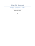
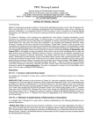
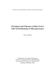
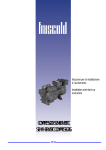
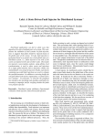
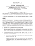
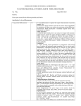
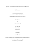
ISSN(Online) : 2319-8753 ISSN (Print) : 2347-6710 International Journal of Innovative Research in Science, Engineering and Technology (An ISO 3297: 2007 Certified Organization) Vol. 4, Issue 7, July 2015 Real Time Tracking and Health Monitoring of Soldiers using ZigBee Technology: a Survey Dineshkumar Jaiswar 1, Sanjna S. Repal 2 P.G. Student, Department of Electronics and Telecommunication Engineering, MCT’s RGIT College, Andheri (W), Mumbai, Maharashtra, India1 Assistant Professor, Department of Electronics and Telecommunication Engineering, MCT’s RGIT College, Andheri (W), Mumbai, Maharashtra, India2 ABSTRACT: Soldiers are very essential part of any nation’s security system. During, wars and search operations soldiers get injured and many of them become lost. As, soldiers health is important because they are the savior of our country who protects us from enemy attacks, terrorist activities and from many suspicious activities which can harm us as well as our nation too. This project gives an ability to track the location and monitor health of the soldiers in real time who become lost and get injured in the battlefield. It helps to minimize the time, search and rescue operation efforts of army control unit. This system enables to army base station to track the location and monitor health of soldiers using GPS module and wireless body area sensor networks (WBASNs), such as temperature sensor, heart beat sensor, etc.. The data coming from sensors and GPS receiver is transmitted wirelessly using ZigBee module. Also, a soldier can ask for help from control room and can communicate with other fellow soldier present within the wireless transmission and reception range. KEYWORDS: ZigBee, GPS, Temperature sensor, Heart beat sensor, ARM 7 microprocessor. I. INTRODUCTION In today’s word, the science and technology is growing rapidly with new inventions, innovations and with advance level of their implementations. These immerging advance technologies are firmly adopted by defense services to provide some safety systems to our soldiers. There are many parameters by which defense services can provide safety to the soldiers. In our project, we are trying to provide an embedded wireless system by which the Army base stations can monitor the heart beat count and body temperature of soldiers using wireless body area sensor networks (WBASNs) such as temperature sensor, heart beat sensor, etc. [1]. Base stations can also know the location of soldiers by tacking them through Global positioning system (GPS) and can guide them to any safe area. Also, the soldier can ask for his location from army control unit in case if he feels that he is lost or to plan any new strategies against enemies. In this project, all the processes are in real time because of the use of ARM 7 microprocessor. The sensed data and the tracked location of soldiers will be transmitted wirelessly using ZigBee module [2]. In military operations, one of the fundamental challenges is that the soldiers are not able to communicate with control room and sometimes not even with the other fellow soldiers. Once a troop or a soldier become lost during fight in battlefield due to some unfavorable environment or adverse fight conditions, then it becomes more difficult to search them and bring back to the army base station. In addition, every defence organization needs to design and develop some advance, small, portable and robust system to provide safety measures to their soldiers. There are many problems which are faced by soldiers during wars in battlefield, like: 1. 2. 3. Sometimes soldiers want to know their location when they become lost but they are not able to do so. Sometimes soldiers need some help during panic situations but they are not able to ask for help. Sometimes soldiers are not able to get help when they get injured during war. Copyright to IJIRSET DOI:10.15680/IJIRSET.2015.0407100 5560 ISSN(Online) : 2319-8753 ISSN (Print) : 2347-6710 International Journal of Innovative Research in Science, Engineering and Technology (An ISO 3297: 2007 Certified Organization) Vol. 4, Issue 7, July 2015 The system proposed by us is composed of two parts, one is small n portable unit for soldiers and other is for army control unit. The soldiers unit consists of an ARM 7 (advanced RISC machine) microprocessor, GPS tracking device, ZigBee transceiver, heart beat sensor, temperature sensor, etc. Where, GPS device is use to track the location of the soldiers with the help of satellite communication system. The heart beat sensor also called pulse rate sensor is use to sense the pulses or heart beats of human heart, and temperature sensor is used to sense the temperature of human body. All the processed and sensed data are transmitted through a ZIGBEE module, which is a low power, low data rate transceiver used to transmit and receive the data wirelessly [1] [2] [3]. In this project, our main aim to improve the communication between soldiers and army control room by using advance and highly efficient, powerful systems. This project helps in to solve above mentioned problems as follows: 1. 2. 3. By using GPS device, it is possible to provide proper information about the location of soldiers when it is needed. It will become possible to help the soldiers in panic situations when it is ask, by communicating with them, using ZigBee technology. It will become easy to provide medical assistance to soldiers when they get injured. II. LITERATURE REVIEW During, wars and military search operations, soldiers get injured and sometimes become lost. To find soldiers and provide health monitoring, army base stations need GPS device for locating soldiers, WBASNs to sense health related parameters of soldiers and a wireless transceiver to transmit the data wirelessly. Hock Beng Lim, Di Ma, Bang Wang, Zbigniew Kalbarczyk, Ravishankar K. Iyer, Kenneth L. Watkin [1] had discussed on recent advances in growing technology, and on various wearable, portable, light weighted and small sized sensors that have been developed for monitoring of the human physiological parameters. The Body Sensor Network (BSN) consists of many biomedical and physiological sensors such as blood pressure sensor, electrocardiogram (ECG) sensor, electro dermal activity (EDA) sensor which can be placed on human body for health monitoring in real time. In this paper, we describe an idea to develop a system for real time health monitoring of soldiers, consisting of interconnected BSNs. We describe the basic prototype of the system and present a blast source localization application. In this paper, we have completed only an initial design of individual sensor nodes and developed a basic prototype of the system to collect the sensed data. In future, we will try to develop an integrated data management system and a web portal which will enable users to have easy access of data. P.S. Kurhe, S.S. Agrawal [4] had introduced a system that gives ability to track the soldiers at any moment. Additionally, the soldiers will be able to communicate with control room using GPS coordinate information in their distress. The location tracking has great importance since World War II, when military forces realized its usefulness for navigation, positioning, targeting and fleet management. This system is reliable, energy efficient for remote soldier health monitoring and their location tracking. It is able to send the sensed and processed parameters of soldier in real time. It enables to army control room to monitor health parameters of soldiers like heart beat, body temperature, etc. using body sensor networks. The parameters of soldiers are measured continuously and wirelessly transmitted using GSM. In this paper, it is possible to transmit the data which is sensed from remote soldier to the base station’s PC by using wireless transmission device like GSM. The accuracy of this system may affected by some factors such as weather, environmental conditions around the soldier’s unit and GPS receiver. The future works in this system may include the optimization of the hardware components, by choosing a suitable and more accurate GPS receiver. By improving the routing algorithm can be make this system more powerful and energy efficient. Upgrading this system is easy which makes it open to an advanced future. Shruti Nikam, Supriya Patil, Prajkta Powar, V. S. Bendre [5] had presented an idea for the safety of soldiers. There are many instruments which can be used to view the health status of soldiers as well as ammunitions on them. The Bio sensor which consists of various types of small physiological sensors, transmission modules have great processing capabilities and can facilitates the low-cost wearable solutions for health monitoring. Copyright to IJIRSET DOI:10.15680/IJIRSET.2015.0407100 5561 ISSN(Online) : 2319-8753 ISSN (Print) : 2347-6710 International Journal of Innovative Research in Science, Engineering and Technology (An ISO 3297: 2007 Certified Organization) Vol. 4, Issue 7, July 2015 GPS module can be used to log the longitude and the latitude by which directions and location can be traceable easily. RF module can be used for high speed, short-range data transmission, for wireless communications between soldier-tosoldier that will help to provide soldiers health status and location data to control room. So by using these devices and modules, we are trying to implement the basic health observing system for soldier in low cost with high efficiency and high reliability. The GPS module tracks the position of soldiers anywhere on the globe and the bio-sensors monitor the vital health parameters of soldiers that provide safety and security to soldiers. By the use of ARM processor and low power hardware peripherals, overall power consumption of system will get reduced. And due to use of small sized modules, the system will be lightweight and can be carried out anywhere. Prof. Pravin Wararkar, Sawan Mahajan, Ashu Mahajan, Arijit Banerjee, Anchal Madankar, Ashish Sontakke [6] had proposed an idea of tracking the position of soldier as well as to give the health status of the soldier, which enables the army base station to plan the strategies according to current situation during war. Use of GPS tracking device and RF transceiver module provide the wireless system to monitor the health parameters and location tracking of soldiers. By using this system, the army base station will come to know the position of soldier and the health parameters such as body temperature and blood pressure of soldiers. The health monitoring and tracking system can be implemented by using RF module and GPS tracking system. By using GPS device, we will able to give proper location of soldier and also can monitor the heath parameters by temperature sensor and heart beat sensor. Thus, we can help the soldiers in panic condition from army control room by communicating with them during war. Rubina.A.Shaikh [10] had investigated for the care of critically ill patients. Considering in India, everyday many people get affected by heart attack, and many of them become more serious, because they did not get proper and timely help of doctors. This paper is based on monitoring the health of remote patients, when they get discharged from hospital. I have tried to design and develop an energy efficient and reliable health monitoring system which is able to send the parameters of patients in real time because of the use of ARM 7 microprocessor. This system enables the doctors to monitor health parameters like body temperature, heartbeat and ECG of patients from their clinic or hospital. The health parameters of patient are measured continuously and transmitted wirelessly through ZigBee transceiver. In this project, we will able to transmit and display the health data which is sensed from remote patients, on the doctor’s PC, using ZigBee module as a wireless transmission device. Additionally, if doctor will not present in clinic or hospital, then too, they will able to receive SMS on their mobile phone, in case of any health parameter increases beyond the normal range using GSM technology. But, to get the more accurate and correct ECG readings, the leads of the ECG sensor should be stick properly on the body of patient, fails to do so; ECG readings will not be accurate. III. PROBLEM STATEMENT In army search operations and wars, soldiers become lost and get injured. There are many developments which give ability to track the location of soldiers at any moment at any place. The aim of these projects is to provide medical monitoring for soldiers in real time. In these existing developments or systems, Bluetooth technology, radio frequency (RF) technology, GSM technology, etc. have been used for wireless transmission of position information and bio sensor’s data of soldiers. There are many shortcomings are present in these existing systems. Some of these existing systems use GSM technology to transmit data wirelessly [4] [8] [9]. The use of GSM technology is restricted in battlefield. Since, GSM protocol stack can be hacked easily by any professional hacker. So, it becomes very easy for enemies to take out the information which will be communicating through GSM module. Therefore, for nation’s security purpose, we have to keep our army control room’s communications and information confidential, private and safe from enemies and hackers. And to achieve this, Network Jammers (CDMA, GSM AND GPRS Jammers) are used in the battlefields. When military war held in hilly area, or in mountain region or in desserts, then usually GSM technology have no network access and it become useless for data transmission, which is a very serious drawback of GSM technology. Copyright to IJIRSET DOI:10.15680/IJIRSET.2015.0407100 5562 ISSN(Online) : 2319-8753 ISSN (Print) : 2347-6710 International Journal of Innovative Research in Science, Engineering and Technology (An ISO 3297: 2007 Certified Organization) Vol. 4, Issue 7, July 2015 So, for security, safety and communication without any network interruption, GSM technology is not safe enough to use in battlefield and in military search operations. In many of existing systems, Bluetooth devices and RF modules have been used to transmit the data wirelessly [5] [6] [7]. But these devices and modules have certain limitations and drawbacks. They are not cost efficient, not energy efficient as they consume more power to operate, and have very short transmission and reception range. To overcome these drawbacks and shortcomings of existing health monitoring and location tracking systems, we have proposed a new system which has capability to transmit the sensed data over a long distance wirelessly using ZigBee mesh technology. As the GSM technology is not useful according to security aspects, we will use ZigBee transceiver module for wireless data transmission and reception. A ZigBee module is a high level communication device use to create wireless personal area networks (WPANs) which is built from small and low power digital radios, and requires very low power to operate. ZigBee devices can transmit data over long distances by passing data through a mesh network of intermediate ZigBee devices to reach up to more distant ones. As ZigBee networks are secured by 128 bit symmetric encryption key, so the hacking of ZigBee modules is not possible for enemies and hackers as in GSM modules [12] [13] [14]. In some of projects, keypads have been provided to input some numerical data by soldiers, which are not so useful and make the system large in size. To overcome this part, we will use a panic button by which a soldier can request for help from control room or from another fellow soldier within the wireless transmission and reception range. IV. PROPOSED SYSTEM ARCHITECTURE The Architecture of our proposed system is composed of two parts: 4.1 Soldier’s Unit This unit consists of body area sensor networks such as temperature sensor and heart beat sensor. These sensors are used to sense the health parameters of soldiers. Temperature sensor will sense the body temperature of soldier and give that sensed data to microcontroller. The heart beat sensor will sense the pulse rate or heart beats of soldiers in beats per minute (BPM) and give it to the microcontroller to process. These sensed analog signals will be converted into digital signals using analog to digital converter and then compared with the normal condition signals. And if any discrepancy occurs between sensed signals and defined normal signals, then it will be considered as an emergency [4] [10] [11]. There will be a GPS modem is used to trace the location of soldiers at any moment from anywhere. The GPS receivers are space-based satellite navigation systems that provide location and time information in all weather conditions from anywhere on or near the earth. The data coming from GPS receiver will pass to microcontroller through IC MAX-232 which converts RS-232 voltage level data to TTL voltage level data and vice versa. The IC MAX-232 is a dual driver/receiver which converts typically RX, TX, CTS, and RTS signals. All the data coming from sensors and GPS modem are processed by ARM 7 microprocessor embedded in LPC 2148 microcontroller. A microprocessor is a single integrated circuit (IC), which is a multipurpose programmable device that takes digital data as input, processes it according to the instructions stored in its memory and provide results as output. The ARM (Advanced RISC machine) processors are based on reduced instruction set computing (RISC), which requires significantly fewer transistors than typical complex instruction set computing (CISC) based processors [4] [5] [8]. This makes them cost efficient, energy efficient and less heat emitting device. These reductions are desirable properties for light, portable and battery powered devices such as smart phones, laptops, tablets, notepads and other embedded systems. A ZigBee transceiver is used to transmit the data, coming from sensors and GPS receiver through microcontroller, to the army control room wirelessly [10] [11]. A ZigBee is low cost, low power, wireless mesh network standard Copyright to IJIRSET DOI:10.15680/IJIRSET.2015.0407100 5563 ISSN(Online) : 2319-8753 ISSN (Print) : 2347-6710 International Journal of Innovative Research in Science, Engineering and Technology (An ISO 3297: 2007 Certified Organization) Vol. 4, Issue 7, July 2015 especially designed and developed for long battery life devices in wireless controlling and monitoring applications. ZigBee devices have low latency which can further reduce the average current. Additionally, an alphanumeric LCD display is used to display the health parameters (i.e. body temperature and heart beats) and location information of soldier. Also a buzzer and a panic switch are provided. A soldier can press the panic switch to ask for help in panic situation from army control room and from another fellow soldier within the wireless range. The buzzer of other fellow soldier will sound when panic button is pressed by the soldier in panic condition. Figure 1: Block Diagram of Soldier’s Unit 4.2 Control Room’s Unit The army base station unit consists of a PC and a ZigBee transceiver. The ZigBee module will be connected to PC with the help of PL-2303 USB-to-Serial driver installed in that PC. The data coming from ZigBee module will be displayed on PC screen with the help of graphical user interface (GUI) coded using visual basic language. Figure 2: Block Diagram of Control Room’s Unit Copyright to IJIRSET DOI:10.15680/IJIRSET.2015.0407100 5564 ISSN(Online) : 2319-8753 ISSN (Print) : 2347-6710 International Journal of Innovative Research in Science, Engineering and Technology (An ISO 3297: 2007 Certified Organization) Vol. 4, Issue 7, July 2015 V. DESIGN DESCRIPTION The design description of our proposed system consists of two main sections: 5.1 Hardware Description The microcontroller we are using is the heart of our proposed system. It will access and analyze all the data coming from sensors and GPS receiver. In our project, ARM 7 microprocessor is used to process all the data in real time. To measure body temperature and heart beats of soldier, there will be a temperature sensor and heart beat sensor is used. Using signal conditioning processes, the analog output of sensors will be converted into strong electrical signal. As the processing is carried out on digital data, so these analog data will be converted into digital data by using ADC which is inbuilt in LPC2148 microcontroller. Therefore the output of the signal conditioning circuit will directly connected to the microcontroller. 5.1.1 LPC2148 Microcontroller The LPC2148 microcontrollers are based on a 32/16 bit ARM7TDMI-S CPU with real-time emulation and embedded trace support, that combines the microcontroller with embedded high speed flash memory ranging from 32 kB to 512 kB. A 128-bit wide memory interface and unique accelerator architecture enable 32-bit code execution at the maximum clock rate. For critical code size applications, the alternative 16-bit Thumb mode reduces code by more than 30 % with minimal performance penalty. Due to their tiny size and low power consumption, LPC2148 are ideal for applications where miniaturization is a key requirement, such as access control and point-of-sale. A blend of serial communications interfaces ranging from a USB 2.0 Full Speed device, multiple UARTs, SPI, SSP to I2C-Bus, and on-chip SRAM of 8 kB up to 40 kB, make these devices very well suited for communication gateways and protocol converters, soft modems, voice recognition and low end imaging, providing both large buffer size and high processing power. Various 32-bit timers, single or dual 10-bit ADC(s), 10-bit DAC, PWM channels and 45 fast GPIO lines with up to nine edge or level sensitive external interrupt pins make these microcontrollers particularly suitable for industrial control and medical systems [15]. The LPC2148 microcontroller has many features, some of which are describe as follows: 1. Fast General Purpose Parallel I/O (GPIO): The device pins that are not connected to a specific peripheral function are controlled by the GPIO registers. Pins may be dynamically configured as inputs or outputs. Separate registers allow setting or clearing any number of outputs simultaneously. The value of the output register may be read back, as well as the current state of the port pins. LPC2148 introduce accelerated GPIO functions over prior LPC2000 devices. Every physical GPIO port is accessible via either the group of registers providing an enhanced feature and accelerated port access or the legacy group of registers. The Accelerated GPIO functions: GPIO registers are relocated to the ARM local bus so that the fastest possible I/O timing can be achieved. Mask registers allow treating sets of port bits as a group, leaving other bits unchanged. All registers are byte and half-word addressable. Entire port value can be written in one instruction. Bit-level set and clear registers allow a single instruction set or clear of any number of bits in one port. Direction control of individual bits. All I/O default to inputs after reset. Backward compatibility with other earlier devices is maintained with legacy registers appearing at the original addresses on the APB bus. Copyright to IJIRSET DOI:10.15680/IJIRSET.2015.0407100 5565 ISSN(Online) : 2319-8753 ISSN (Print) : 2347-6710 International Journal of Innovative Research in Science, Engineering and Technology (An ISO 3297: 2007 Certified Organization) Vol. 4, Issue 7, July 2015 Separate control of output set and clear. 2. 10-Bit ADC: The LPC2148 contain two analog to digital converters. These converters are single 10-bit successive approximation analog to digital converters. While ADC0 has six channels, ADC1 has eight channels. Therefore, total number of available ADC inputs for LPC2148 is 14. Basic clocking for the A/D converters is provided by the APB clock. A programmable divider is included in each converter, to scale this clock to the 4.5 MHz (max) clock needed by the successive approximation process. A fully accurate conversion requires 11 of these clocks. Features of ADC: 10 bit successive approximation analog to digital converter (i.e. two in LPC2148). Input multiplexing among 6 or 8 pins (ADC0 and ADC1). Power-down mode. Measurement ranges 0V to VREF (typically 3V; not to exceed VDDA voltage level). 10 bit conversion time ≥ 2.44 µs. Burst conversion mode for single or multiple inputs. Optional conversion on transition on input pin or Timer Match signal. Global Start command for both converters. 5.1.2 ARM7 Microprocessor The LPC2148 is embedded with ARM7TDMI-S microprocessor. The TDMI-S stands for 16-bit Thumb + JTAG Debug + fast Multiplier + enhanced ICE + Synthesizable core. Where T: supports both ARM (32-bit) and Thumb (16-bit) instruction sets, D: Contains Joint Test Action Group (JTAG) Debug extensions, M: Enhanced 32x8 Multiplier block, I: Embedded In-Circuit Emulator (ICE) macro cell, S: Synthesizable (i.e. distributed as Register Transfer Level (RTL) rather than a hardened layout).The ARM7TDMI-S is a general purpose 32-bit microprocessor, which offers high performance and very low power consumption [15]. The ARM architecture is based on Reduced Instruction Set Computer (RISC) principles, and the instruction set and related decode mechanism are much simpler than those of micro programmed Complex Instruction Set Computers (CISC). This simplicity results in a high instruction throughput and impressive real-time interrupt response from a small and cost-effective processor core. Pipeline techniques are employed so that all parts of the processing and memory systems can operate continuously. Typically, while one instruction is being executed, its successor is being decoded, and a third instruction is being fetched from memory. The ARM7TDMI-S processor also employs a unique architectural strategy known as THUMB, which makes it ideally suited to high-volume applications with memory restrictions, or applications where code density is an issue. The key idea behind THUMB is that of a super-reduced instruction set. Essentially, the ARM7TDMI-S processor has two instruction sets: • The standard 32-bit ARM instruction set. • A 16-bit THUMB instruction set. The THUMB set’s 16-bit instruction length allows it to approach twice the density of standard ARM code while retaining most of the ARM’s performance advantage over a traditional 16-bit processor using 16-bit registers. This is possible because THUMB code operates on the same 32-bit register set as ARM code. THUMB code is able to provide up to 65% of the code size of ARM, and 160% of the performance of an equivalent ARM processor connected to a 16 bit memory system. Copyright to IJIRSET DOI:10.15680/IJIRSET.2015.0407100 5566 ISSN(Online) : 2319-8753 ISSN (Print) : 2347-6710 International Journal of Innovative Research in Science, Engineering and Technology (An ISO 3297: 2007 Certified Organization) Vol. 4, Issue 7, July 2015 5.1.3 Temperature Sensor LM35 The LM35 series devices are precision integrated-circuit temperature sensors, with an output voltage linearly proportional to the Centigrade temperature. The LM35 device has an advantage over linear temperature sensors calibrated in Kelvin, as the user is not required to subtract a large constant voltage from the output to obtain convenient Centigrade scaling. The LM35 device does not require any external calibration or trimming to provide typical accuracies of ± ¼ °C at room temperature and ± ¾ °C over a full −55°C to 150°C temperature range. Lower cost is assured by trimming and calibration at the wafer level. The low output impedance, linear output, and precise inherent calibration of the LM35 device makes interfacing to readout or control circuitry especially easy. The device is used with single power supplies, or with plus and minus supplies. As the LM35 device draws only 60 µA from the supply, it has very low self-heating of less than 0.1°C in still air. The LM35 device is rated to operate over a −55°C to 150°C temperature range, while the LM35C device is rated for a −40°C to 110°C range [16]. Figure 3: Full-Range Centigrade Temperature Sensor LM35 5.1.4 Heart Beat Sensor IC LM358 Heart beat sensor is designed to give digital output of heart beat when a finger is placed on it. This digital output will be interfaced to LPC2148 microcontroller directly to measure the heartbeats in Beats per Minute (BPM) rate. It works on the principle of light modulation by blood flow through finger at each pulse. The comparator IC LM358 is used in Heart Beat Sensor prototype. The LM358 consists of two independent, high gain, internally frequency compensated operational amplifiers which were designed specifically to operate from a single power supply over a wide range of voltages. The low-power, dual operational amplifiers are connected to a light detector. Out of two op-amps, one will act as an amplifiers and another will be used as comparator for the output of light detector [4] [9] [10] [11]. The LED used needs to be super bright as the maximum light must pass spread in finger and detected by light detector. Now, when the heart pumps a pulse of blood through the blood vessels, the finger becomes slightly more opaque and so less light reached to the detector. With each heart pulse, the detector signal varies. This variation is converted to electrical pulse. This signal is amplified and triggered through an amplifier which outputs +5V TTL/CMOS level signal. Copyright to IJIRSET DOI:10.15680/IJIRSET.2015.0407100 5567 ISSN(Online) : 2319-8753 ISSN (Print) : 2347-6710 International Journal of Innovative Research in Science, Engineering and Technology (An ISO 3297: 2007 Certified Organization) Vol. 4, Issue 7, July 2015 Figure 4: Heart Beat Measurement Principle 5.1.5 GPS MODULE SIM28M The concept of GPS is based on time and position. Far from North Pole and South Pole, a GPS unit can receive signals from 6 to 12 visible satellites at once. The satellites contain very stable atomic clocks that are synchronized to ground clocks and to each other also. The satellite locations are monitored precisely and any drift from true time which is maintained on the ground is corrected daily. The GPS satellites continuously transmit their current time and position. A GPS receiver monitors multiple satellites and solves equations using trigonometry to determine the exact position of the receiver and its deviation from true time. There has to be at least four satellites in view for the GPS receiver to solve the geometric equations. A GPS receiver can calculate its position many times in one second. A GPS receiver calculates its speed and direction by using its change in position and change in time. Generally, the messages received by GPS receiver are in NMEA (National Marine Electronics Association) message format and the most commonly used NMEA protocol is NMEA-0183 protocol. NMEA Message Prefix $GPGGA $GPGLL $GPGSA $GPGSV $GPMSS $GPRMC $GPVTG $GPZDA Description Direction Time, position and fix type data. Latitude, longitude, UTC time of position fix and status. GNSS DOP and Active satellites. GNSS Satellites in View. Signal-to-noise ratio, signal strength, frequency, and bit rate from a radiobeacon receiver. Time, date, position, course and speed data. Course and speed information relative to the ground. Precise Positioning Service (PPS) timing message (synchronized to PPS). Out Out Out Out Out Out Out Out Table 1: Format of NMEA Output Messages In this project, we are using SIM28M GPS receiver designed by SIMCom, which is use to track the location at anytime from anywhere. SIM28M is a stand-alone or A-GPS (Assisted Global Positioning System) receiver with built in low noise amplifier (LNA). Therefore, SIM28M can relax antenna requirement and don’t need for any external LNA. The SIM28M can track as low as -165dBm signal even without network assistance. The SIM28M has excellent low power consumption characteristics i.e. for acquisition 17mA and for tracking 16mA. SIM28M supports various location and navigation applications, including autonomous GPS, QZSS, SBAS ranging (EGNOS, GAGAN, MSAS, and WAAS), DGPS and A-GPS [17]. Copyright to IJIRSET DOI:10.15680/IJIRSET.2015.0407100 5568 ISSN(Online) : 2319-8753 ISSN (Print) : 2347-6710 International Journal of Innovative Research in Science, Engineering and Technology (An ISO 3297: 2007 Certified Organization) Vol. 4, Issue 7, July 2015 Key features of SIM28M: 22 tracking and 66 acquisition channels, up to 210 PRN channels. Small footprint: 10.1*9.7*2.5 mm, 18-pin LCC package. 12 multi-tone active interference cancellers and jamming elimination. Indoor and outdoor multi-path detection and compensation. Max NMEA update rate up to 10 Hz. Advanced software features: 1) EASY self-generated orbit prediction. 2) EPO/HotStill orbit prediction. 3) Always locate advanced location awareness technology. 4) Supports logger function. 5) Supports Active Interference Cancellation (AIC). Pulse-per-second (PPS) GPS time reference: 1) Adjustable duty cycle. 2) Typical accuracy: ±10 ns. Interface: UART0/UART1. Operating temperature: -40°C ~ +85°C. Accuracy 2.5m CEP (Circular Error Probable). RoHS (Restriction of Hazardous Substances Directive) compliant. The SIM28M module provides complete signal processing from antenna input to host port in NMEA messages format. It requires 2.8V~4.3V power supply. The host port is configurable to UART. The host data and I/O signal levels are 2.85V CMOS compatible. Figure 5: GPS Module SIM28M 5.1.6 ZigBee Module NORDIC nRF24L01+ ZigBee is based on an IEEE 802.15.4 standard which is a packet-based radio protocol. It is use to provide the communication which needs wireless applications that have low data rates and requires low power consumption. ZigBee has a defined rate of 250 Kbit/s, which is best suited for intermittent data transmissions from a sensor or input device. This module has worldwide 2.4GHz ISM (The industrial, scientific and medical radio bands) bands and ultra low power operation. The ZigBee standard provides wireless networking, security, and application support services that operate on the basis of IEEE 802.15.4 Medium Access Control (MAC) and Physical Layer (PHY) wireless standard. It uses a suite of technologies which enable the self-organizing, self-healing and scalable networks that is efficient enough to manage various data traffic patterns. Copyright to IJIRSET DOI:10.15680/IJIRSET.2015.0407100 5569 ISSN(Online) : 2319-8753 ISSN (Print) : 2347-6710 International Journal of Innovative Research in Science, Engineering and Technology (An ISO 3297: 2007 Certified Organization) Vol. 4, Issue 7, July 2015 ZigBee is a low-cost, low-power, and wireless mesh networking standard device. The low cost allows this technology to be widely accepted in wireless control and monitoring applications. The low power consumption provides longer life with smaller batteries and the mesh networking provides high reliability and larger range of data transmission. ZigBee technology has been developed to fulfill the need of advanced wireless networking between various low power devices, sensors and modules [12] [13] [14]. In our system, ZigBee module nRF24L01+ of Nordic Semiconductors is used. The nRF24L01+ is a single chip 2.4GHz transceiver with an embedded baseband protocol engine (Enhanced ShockBust™), suitable for ultra low power wireless applications. The nRF24L01+ is designed for operation in the world wide ISM frequency band at 2.400-2.4835GHz. To design radio system with the nRF24L01+, we simply need an MCU and a few external passive components. We can operate and configure the nRF24L01+ through a Serial Peripheral Interface (SPI).The register map, which is accessible through SPI, contains all configuration registers in the nRF24L01+ and is accessible in all operation modes of the chip. The embedded baseband protocol engine (Enhanced ShockBust™) is based on packet communication and support various modes from manual operation to advanced autonomous protocol operation. Internal FIFOs ensure a smooth data flow between the radio front end and the system’s MCU. Enhanced ShockBust™ reduces system cost by handling all the high speed link layer operations. The radio front end uses GSFK modulation. It has over configurable parameters like frequency channel, output power and air data rate. The nRF24L01+ supports an air data rate of 250 kbps, 1 Mbps and 2 Mbps. The high air data rate combined with two powers saving modes make the nRF24L01+ very suitable for ultra low power designs. The nRF24L01+ is drop in compatible with nRF24L01 and on air compatible with nRF2401A, nRF2402, nRF24E1 and nRF24E2. Intermodulation and wideband blocking values in nRF24L01+ are much improved in comparison to the nRF24L01 and the addition of the internal filtering to nRF24L01+ has improved the margins for meeting RF regulatory standards. Internal voltage regulators ensure a high Power Supply Rejection Ratio (PSRR) and a wide power supply [18]. Figure 6: NORDIC nRF24L01+ Plugin 5.1.7 IC MAX232 The MAX232 is a Maxim Integrated Product designed in 1987. It converts signal from RS-232 level to signal suitable for use in TTL/CMOS compatible logic circuits and vice-versa. The MAX232 IC is a dual driver/receiver that includes a capacitive voltage generator to supply TIA/EIA-232-F (RS-232) voltage levels from a single 5V supply. Each receiver converts TIA/EIA-232-F inputs to 5V TTL/CMOS levels. These receivers have a typical threshold of 1.3V, a typical hysteresis of 0.5V, and can accept ±30V inputs. Each driver converts 5V TTL/CMOS input levels into TIA/EIA-232-F levels. The TIA/EIA-232-F stands for Telecommunications Industry Association/Electronic Industries Alliance-232-F, which is more popularly referred to RS-232 where ‘RS’ stands for ‘Recommended Standard’. Copyright to IJIRSET DOI:10.15680/IJIRSET.2015.0407100 5570 ISSN(Online) : 2319-8753 ISSN (Print) : 2347-6710 International Journal of Innovative Research in Science, Engineering and Technology (An ISO 3297: 2007 Certified Organization) Vol. 4, Issue 7, July 2015 Figure 7: MAX232 Board 5.1.8 Alphanumeric LCD Display Alphanumeric displays are used in a wide range of applications, including palmtop computers, word processors, photocopiers, point of sale terminals, medical instruments, cellular phones, calculators, etc. The 16 x 2 intelligent alphanumeric dot matrix display is capable of displaying 224 different characters and symbols. We are using this LCD to display the health parameters measured by different sensors used and location information given by GPS module. Figure 8: Alphanumeric LCD Display 5.1.9 Panic Button A panic button or a switch will be providing in this system, so that a soldier can request for his help in panic situation by pressing it. As a soldier will press the panic button, the buzzer provided in the system will sound, of another fellow soldier’s unit and he will able to get help of that fellow soldier which is present within the ZigBee range. Figure 9: Panic Button 5.1.10 Buzzer A buzzer is used to generate sound signal when panic button is pressed to get help from another fellow soldier in panic situation. Copyright to IJIRSET DOI:10.15680/IJIRSET.2015.0407100 5571 ISSN(Online) : 2319-8753 ISSN (Print) : 2347-6710 International Journal of Innovative Research in Science, Engineering and Technology (An ISO 3297: 2007 Certified Organization) Vol. 4, Issue 7, July 2015 Figure 10: Buzzer 5.1.11 Power Supply In every electronic circuit, power supply is the most important part. An appropriate power supply is needed for proper working of components. The power supply must have capability to provide the necessary power for each component and also the protection from excess voltage supply. In this project, the following voltage regulators are used to provide necessary power supply: A constant voltage regulator LM7805 is used to supply 5V to all the peripherals except the main microcontroller which works on 3.3V. The LM7805 can add with adequate heat sink to deliver output current in excess of 1A. It has internal thermal overload protection and internal short circuit current limiting with output transistor safe operating area protection. A constant voltage regulator LM1117 is used to supply 3.3V for LPC2148 microcontroller. It is a low dropout regulator with a dropout of 1.2V at 800mA of load current. It offers current limiting and thermal protection. Figure 11: C.V.R. LM7805 and LM1117 Pin out Diagram 5.2 Software Description Software is a basic building block for the every system which designs the processing and operations. Following are the software’s used in designing of the proposed system. For programming of ARM7 microprocessor, embedded c language using Keil µVision4 software is used. The new Keil µVision4 IDE has been designed to enhance developer's productivity, also enabling faster and more efficient program development. µVision4 introduces a flexible window management system, enables us to drag and drop individual windows anywhere on the visual surface including support for Multiple Monitors. The Graphical user interface (GUI) coding needs VB.Net language. Visual Basic is a legacy third generation event driven programming language and integrated development environment (IDE) Microsoft. Microsoft intended Visual Basic to be relatively easy to learn and use. Visual Basic was derived from BASIC (Beginner’s All-purpose Symbolic Instruction Code) and enables the rapid application development (RAD) of graphical user interface (GUI) applications, access to databases using Data Access Objects, Remote Data Objects, or ActiveX Data Objects, and creation of ActiveX controls and objects. To display the data received by ZigBee on servers PC, a PL-2303 driver for Usb-to-Serial adapter has installed on that PC. This driver helps to access the data on PC, through Usb adapter of ZigBee transceiver. Copyright to IJIRSET DOI:10.15680/IJIRSET.2015.0407100 5572 ISSN(Online) : 2319-8753 ISSN (Print) : 2347-6710 International Journal of Innovative Research in Science, Engineering and Technology (An ISO 3297: 2007 Certified Organization) Vol. 4, Issue 7, July 2015 To designing the schematic circuit diagram and PCB Layout, Cadsoft EAGLE software is used. This software is less complex, easy to learn and helps to design circuit diagram in professional manner. 5.3 Advantages of Proposed System It will provide high level safety to Soldiers life. This system will be suitable for all environmental conditions. Continuous data logging can provide the analysis for different soldiers. It is low cost, compact and less complex system which can be easily adopted by any military force. Due to use of advanced technology and advanced equipments, this system will fulfill all the requirements of growing technologies. VI. METHODOLOGY In this project, our aim is to track the location of soldiers in the battle field, military search operations and to provide real time health monitoring to soldiers. So, in order to implement this project, we will use the GPS receiver to track the location of the soldiers through satellite. LM 35 which is a temperature sensor senses the body temperature of the soldiers. An IC LM358 will be use to sense the heart beat of the solders. We will use LPC2148 microcontroller which is embedded with ARM 7 microprocessor to process all the received data through sensors and GPS receiver in real time. A ZigBee module will be use for wireless transmitting and receiving of data. The data received from GPS modem is a RS-232 level data, therefore, we have to use IC MAX232, which convert the RS-232 voltage level data to 5V TTL/CMOS level. An alphanumeric LCD display is used to display the data sensed from BSNs and coming from GPS modem. To implement this hardware design, we will require software like Keil µVision4, Cadsoft Eagle and VB.net. To write program using language embedded c in ARM 7 microprocessor for LM 35 temperature sensor, IC LM358 heart beat sensor, GPS modem and ZigBee module, we will use Keil µVision4 software, which is an Integrated Development Environment (IDE) for ARM microprocessors. To design the circuit, we will require Cadsoft Eagle i.e. (Easily Applicable Graphical Layout Editor) software which easy to understand and user friendly. It is the latest and advance software for schematic electrical circuit designing and PCB layout. This is a flexible, expandable and scriptable EDA (Electronic Design Automation)/ ECAD (Electronic Computer Aided design) application with schematic capture editor, PCB layout editor, auto-router and CAM (Computer Aided Manufacturing) and BOM (Bill of Material) tools developed by CadSoft Computer. The graphical user interface (GUI) provides easy understanding of the string data. This data is received wirelessly using Zigbee from the Soldier’s side. Data consists of location, Body Temperature and Heart rate information which will be continuously logged for the analysis and tracking. Visual Basics will provide a platform to design a customized graphical environment for the user. VII. CONCLUSION From above proposed system, we can conclude that we are able to transmit data which is sensed from remote soldier to army control room using ZigBee transceiver as a wireless transmission technology. The system is completely integrated and can track the location of soldier at anytime from anywhere on the earth using GPS receiver. This system helps to monitor health parameters of soldier using heart beat sensor to measure heart beats and temperature sensor to measure body temperature of soldier. This system helps the soldier to get help from army base station and/or from another fellow soldier in panic situation. This system provides the location information and health parameters of soldier in real time to the army control room. This system is very useful to military forces during war as it can be used in battlefield without any network restriction. Thus, this system provides security and safety to our soldiers. Copyright to IJIRSET DOI:10.15680/IJIRSET.2015.0407100 5573 ISSN(Online) : 2319-8753 ISSN (Print) : 2347-6710 International Journal of Innovative Research in Science, Engineering and Technology (An ISO 3297: 2007 Certified Organization) Vol. 4, Issue 7, July 2015 REFERENCES [1] Hock Beng Lim, Di Ma, Bang Wang, Zbigniew Kalbarczyk, Ravishankar K. Iyer, Kenneth L. Watkin, “A Soldier Health Monitoring System for Military Applications”, 2010 International Conference on Body Sensor Networks, 978-0-7695-4065-8/10/$26.00 © 2010 IEEE, DOI: 10.1109/BSN.2010.58, pp: (246-249). [2] William Walker, A. L. Praveen Aroul, Dinesh Bhatia, “Mobile Health Monitoring Systems”, 31st Annual International Conference of the IEEE EMBS, Minneapolis, Minnesota, USA, September 2-6, 2009, 978-1-4244-3296-7/09/$25.00 © 2009 IEEE, pp: (5199-5202). [3] M. Pranav Sailesh, C. Vimal Kumar, B. Cecil, B. M. Mangal Deep, P. Sivraj, “Smart Soldier Assistance using WSN”, International Conference on Embedded Systems - (ICES 2014), 978-1-4799-5026-3/14/$31.00 © 2014 IEEE, pp: (244-249). [4] P.S. Kurhe, S.S. Agrawal, “Real Time Tracking and Health Monitoring System of Remote Soldier Using ARM 7”, International Journal of Engineering Trends and Technology, ISSN: 2231-5381, Volume 4, Issue 3, No. 1, March 2013, pp: (311-315). [5] Shruti Nikam, Supriya Patil, Prajkta Powar, V. S. Bendre, “GPS Based Soldier Tracking and Health Indication System”, International Journal of Advanced Research in Electrical, Electronics and Instrumentation Engineering, ISSN: 2278-8875, Volume 2, Issue 3, March 2013, pp: (1082-1088). [6] Prof. Pravin Wararkar, Sawan Mahajan, Ashu Mahajan, Arijit Banerjee, Anchal Madankar, Ashish Sontakke, “Soldier Tracking and Health Monitoring System”, The International Journal of Computer Science & Applications, ISSN: 2278-1080, Volume 2, No. 02, April 2013, pp: (81-86). [7] Govindaraj A., Dr. S. Sindhuja Banu, “GPS Based Soldier Tracking and Health Indication System with Environmental Analysis”, International Journal of Enhanced Research in Science Technology & Engineering, ISSN: 2319-7463, Volume 2 Issue 12, December 2013, pp: (46-52). [8] Palve Pramod, “GPS Based Advanced Soldier Tracking With Emergency Messages & Communication System”, International Journal of Advance Research in Computer Science and Management Studies, ISSN: 2321-7782, Volume 2, Issue 6, June 2014, pp: (25-32). [9] Mr. Rajdeep Limbu, Prof. V. V. Kale, “GPS Based Soldier Tracking and Health Monitoring System”, International Journal for Technological Research in Engineering, ISSN: 2347-4718, Volume 1, Issue 12, August 2014, pp: (1485-1488). [10] Rubina.A.Shaikh, “Real Time Health Monitoring System of Remote Patient Using Arm7”, International Journal of Instrumentation, Control and Automation, ISSN: 2231-1890, Volume 1, Issue 3-4, April 2012, pp: (102-105). [11] Ekta Madhyan, Mahesh Kadam, “A Unique Health Care Monitoring System Using Sensors and ZigBee Technology”, International Journal of Advanced Research in Computer Science and Software Engineering, ISSN: 2277-128X, Volume 4, Issue 6, June 2014, pp: (501-509). [12] Dr. S. S. Riaz Ahamed, “The Role of ZigBee Technology in Future Data Communication System”, Journal of Theoretical and Applied Information Technology, ISSN: 1817-3195, Volume 5, No. 2, February 2009, pp: (129-135). [13] Nisha Ashok Somani, Yask Patel, “ZigBee: A Low Power Wireless Technology for Industrial Applications”, International Journal of Control Theory and Computer Modeling, ISSN: 2249-1155, Volume 2, No. 3, May 2012, DOI: 10.5121/ijctcm.2012.2303, pp: (27-33). [14] P. Rohitha, P. Ranjeet Kumar, Prof. N. Adinarayana, Prof. T. Venkat Narayana Rao, “Wireless Networking through ZigBee Technology”, International Journal of Advanced Research in Computer Science and Software Engineering, ISSN: 2277-128X, Volume 2, Issue 7, July 2012, pp: (49-54). [15] NXP Semiconductors, UM10139, LPC 214X User Manual, Rev. 4, 23 April 2012, pp: (1-354). [16] Texas Instruments Inc., LM 35 Datasheet, SNIS159E-August 1999-Revised January 2015, pp: (1-31). [17] SIMCom Wireless Solutions Ltd., SIM28M Hardware Design V1.00, January 2014, pp: (1-29). [18] Nordic Semiconductor, nRF24L01+ Single Chip 2.4GHz Transceiver, Product Specification V1.0, September 2008, pp: (1-78). Copyright to IJIRSET DOI:10.15680/IJIRSET.2015.0407100 5574