1
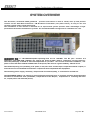
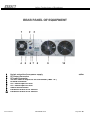
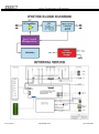
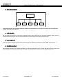
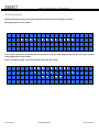
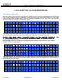
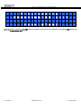
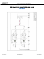
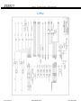
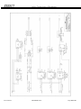
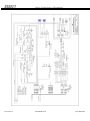
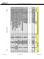
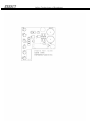
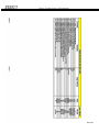
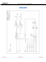
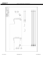
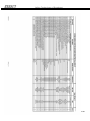
Italian Technology of Broadcast ARCHIMEDE 2000 Operating Manual Via Casale 3/A 20144 Milano Italy Phone: (39) 02 90389417 Fax: (39) 02 23168389 E-mail: [email protected] WebSite: www.italab.it ITALAB reserves the right to revise and change any and all information included in this document. Ediz./Rev. Data (gg/mm/aa) Motivo Approvato da: ARC2000-A/00 20/06/2011 First Edition M.N. ARC2000-A/00 18/09/2014 Second Edition M.N. User's Manual ARCHIMEDE 2000 Page 1 of 40 Italian Technology of Broadcast Warranty Italab product is guaranteed against defects in materials and workmanship for a period of TWO YEARS from date of shipment. The standard warranty may be extended beyond the two-year period. A record of warranty extensions is listed on sales orders of each product purchased. Standard warranty conditions apply to extended warranty period. During warranty Italab will repair or replace product proved to be faulty prior to authorization. The warranty validation only applies if product is returned to Italab after release of Return of Merchandise Authorization and provided that maintenance procedures are followed as listed in the manual. Warranty does not cover repair resulting from product carelessness, incorrect or improper use. NO OTHER WARRANTY APPLIES ITALAB IS NOT LIABLE FOR DAMAGES RESULTING FROM PRODUCT MISUSE ITALAB DOES NOT GUARANTEE ERROR-FREE EQUIPMENT, UNINTERRUPTED OPERATION, FIRMWARE OR FIRMWARE BUGS. If your Equipment needs repairing call Italab promptly and ask for customer service department. It is important to contact Italab immediately since many problems may be quickly solved over the phone or by e-mail. Please have your Serial Number ready before you contact Italab and clearly explain the nature of your problem. Once we acknowledge your Equipment needs service, we will send you an electronic form to fill in with your name, address, phone number, e-mail and an accurate description of problem or failure. We will issue an RMA number. Send the unit with prepaid shipment to the indicated maintenance lab and place the Equipment in the original box or a suitable container to protect product from damage. Italab will not be responsible for damage incurred during shipping. Please ensure RMA number is clearly marked onto shipping container. Our standard terms are to fix or repair Equipment within five working days. If Equipment requires parts ordering or more than five working days, Italab technical service will contact you. We also provide service for Equipment if warranty has expired. Please, follow the same instructions described above, but tick in the “not in warranty” box. Warranty is valid on condition that proper maintenance procedures have been complied with, as listed in the manual. Damage caused by product misuse is NOT covered by warranty. Warranty Service The Archimede 2000 is a high reliability equipment. Nevertheless, as any equipment which works 24 hours a day for years, some failures are possible. Because the reparation of the modules, inside the Amplifier, is very difficult on the field, we suggest in the event of any failure to contact our service. ITALAB Via Casale 3/A 20144 Milano Italy Phone: (39) 02 90389417 - Fax: (39) 02 23168389 User's Manual ARCHIMEDE 2000 Page 2 of 40 Italian Technology of Broadcast Table of Contents Warranty Safety Instructions System overview Technical features Front Panel Rear panel Internal overview Installation to start up System start up System block diagram and Internal Connections Circuit description RF amplifier box CPU board Analog board Led board Lcd display Power supply page 2 4 6 7 8 9 10 11 12 13 14/15 14 14 15 15 15 15 LCD display screens Power on Start of transmission Stop sequence 16 16 16 17 LCD display alarm screens FWR alarm SWR alarm Temperature alarm User Programming Programming clock Programming language Programming name Programming exit Schematic drawings and BOM 18 18 18 19 20 21 22 23 24 25 User's Manual ARCHIMEDE 2000 Page 3 of 40 Italian Technology of Broadcast Safety Instructions To maximize user safety and ensure the Device to operate correctly , all instructions contained in this section should be read carefully. OPERATING CONDITIONS This Equipment operates with: AC 50÷60 Hz power source of between 190-265 V temperature range from 0 up to 40°C. Maximum altitude of 4000 m ATTENTION : hazardous voltages are present inside the Equipment. ONLY AUTHORIZED AND QUALIFIED PERSONNEL CAN REMOVE PARTS OF THE EQUIPMENT GROUND THE AMPLIFIER To minimize shock hazard, the Amplifier chassis must be connected to an electrical ground through the AC power mains cable, with the third wire ( yellow green ) connected to an electrical ground (safety ground) at the power outlet. Any interruption of the grounding conductor will cause a potential shock hazard that could result in personal injury. If the Amplifier is powered by any other source, make sure that the chassis is connected to a separate safety ground DO NOT OPERATE IN AN EXPLOSIVE ATMOSPHERE Operation of the Archimede 2000 in presence of flammable gasses or fumes can endanger persons proximate to the site of operation. DO NOT REPAIR THE ARCHIMEDE Component maintenance, replacement and internal adjustments must be made only by ITB qualified service personnel. Fuses In the event of fuses failure, only fuses with the same required current, voltage rating, and specified type should be used. Do not use repaired fuses or short-circuited fuse holders. Output Connector The “7/16” output connector carries dangerously high RF voltages that could cause shock and burn hazards. Never operate the Amplifier without properly connecting the output connector in either an adequately rated load or antenna. Electrostatic Discharge (ESD) A sudden discharge of electrostatic electricity can destroy static-sensitive devices or micro-circuits. Proper grounding techniques are necessary precautions to prevent damage. Always take industry-standard precautions. User's Manual ARCHIMEDE 2000 Page 4 of 40 Italian Technology of Broadcast General Safety Rules The device must be used in accordance with the instructions for use. Electrical installations in the room must correspond to the requirements of safety regulations. Take care that there are no cables, especially mains cables, in areas where people could move or work. Do not use a mains connection in sockets shared by other power consumers. Do not use an extension cable. Only use the mains cable supplied. In the case it is not long enough, only use a cable with the same characteristics as the one provided to assemble a longer one. The unit is completely disconnected from the power source only when the power cord is removed from power source. Therefore the power cord and its connectors must always remain easily accessible. Do not set up the device in the proximity of heat sources or in a damp location. Make sure that the device has adequate ventilation. The Amplifier should not be used near water and objects filled with liquids should not be placed on the appliance. The Amplifier should be situated so that its location or position does not interfere with its proper ventilation. For example, the device should not be placed in a built-in installation, such as a bookcase or cabinet that may stop the flow of air through the ventilation openings. All plugs on the connection cables must be screwed or locked to the chassis housing. The device is designed to be used in horizontal position only. The device is no longer safe to operate when has visible damage or it hasn’t been working for long time. In case of technical problems or a few elements of doubt, Italab will help you with the support of qualified technical personnel. In case of system failure or visible damage, the device must be shut down. Repairs may only be carried out by a person authorized by ITALAB. The ARCHIMEDE 2000 must be switched off and the power cord disconnected from the AC source when removing the top cover. Climatic Conditions In order to have the best performance in term of power, life span, etc, the following parameters must be respected: the room temperature should be in a range of 25° C and 30°C . The humidity shall be less than 70% and non-condensing. The Equipment will work beyond the parameters specified, but Italab will not guarantee the continuous service and, in any case, with temperatures higher than 50°inside the Equipment, the standby procedure will automatically start. The room must have a good ventilation to ensure that the inside temperature never exceeds the limit of 40 °C. If the Equipment is included in a rack, the rear of this should not be closed. If it is necessary to close the rear of the Device, a forced ventilation and air extraction must be provided. User's Manual ARCHIMEDE 2000 Page 5 of 40 Italian Technology of Broadcast SYSTEM OVERVIEW This document, Archimede 2000 guidebook , provides instructions on how to install, start up and perform controls on the 2000 Watt Archimede FM Broadcast Transmitter (see photo below), an easy-to use and versatile system used in stand-alone mode. The information on this manual is intended for an experienced system operator with a knowledge of highperformance broadcast transmission systems. The Archimede 2000 is designed to fit a standard 19” rack. ARCHIMEDE 2000 is a broadband amplifier operating from 87.5 to 108 MHz. The RF part consists of 2 amplifying units (AMP1000 - FM) that can deliver full power to 2500 watts in continuous service. However, since the philosophy of Italab to allow all components of a product “not to work in stressful conditions ," the power of work has been limited to 2000 watts at full speed, this ensures a good reliability without stress. The Radiofrequency part (including a RF pallet, a low-pass filter and the input / output directional coupler) is inserted in a box and shielded from all other components that complement this Equipment. The switching power supply, extremely compact and of excellent quality, is oversized for its final use. The ARCHIMEDE 2000 is run entirely by a powerful microprocessor that in real time controls all the important functions for an efficient work (ventilation, temperatures of the RF part, temperature of incoming and inner air, output power and reflected power). User's Manual ARCHIMEDE 2000 Page 6 of 40 Italian Technology of Broadcast TECHNICAL FEATURES Technology • Solid state power MOSFET technology • Master control by microprocessor with stored program RF Specification Frequency………….......................................................................................................................87.5 ÷ 108 MHz Input Power.......................................……………………..………..................................................8 - 10 Watts Max Output Power........................................…………………………….................................................... 0 ÷ 2000 Watts Harmonics.............................………………..………............................................................................... ≤ - 70 dBc Output Connector.........................................………….…............................................................................ 7/16 “ Input Connector..............................................………….…......................................................................... N type OTHER Voltage Input…………………………………………………………………………...……………………………..190 ÷ 265 Vac Current Input ………………………………………………………………………………………………………...14 A & 230Vac Protections……..............................................................................................Overload, VSWR and Temperature Cooling..............................…………………..………………………………………………………………........... Forced Air Working Ambient Temperature .......…………………………...……......................................................... 0 ÷ +40 °C Storage Temperature .......……………………………........................................................................... -10 ÷ +60 °C Umidity……………................................................................................……………........................................ 90 % Control System.........................................................................................................2 buttons, 4x20 LCD display Dimension ................................................................................................................... 3 unity rack 19", 530mm Weigh........................................................................................................................................................ 18 Kg Box Material .........................................................................................................................Alodyne Aluminium The user must obtain a license before using the product in the intended country of use. Ensure respective country licensing requirements are complied with. Limitations of use can be applied in respect of operating frequency, transmitter power and/or channel spacing. Italab is not criminally and civilly liable for a not-legally authorized use. User's Manual ARCHIMEDE 2000 Page 7 of 40 Italian Technology of Broadcast FRONT PANEL 1 2 3 4 5 6 7 8 9 10 RF TEST (SMA connector output signal test– 60dBc ÷ 3 dB ) option STOP button Stop button START button Start button Led ST.BY Standby status led Led On AIR Power broadcast led Led BLOCK Spy Led block Led TEMP Alarm led for overheating Led RF OUT Spy Led RF out Led REFL Spy Led refl DISPLAY Operation display DESCRIPTION LED SWR: Blinking: indicates that the output RF power is being limited in order to reduce the reflected power Steady light: indicates that the reflected power is greater than 12% of the nominal power of the Equipment LED PWR: Blinking: indicates that the Equipment is limiting the output power in order not to exceed the nominal power. Steady light: indicates that the output power is greater than the nominal power Steady light: indicates that the sensors, placed inside the Equipment, detect a temperature of the apparatus or pallet higher than the safety parameters. Blinking: indicates that the CPU is reducing the bias voltage to the MOSFET. Blinking: indicates that the Amplifier is operating but there is no output signal over 15% nominal maximum. Steady light: indicates that the Equipment is deriving the output power Steady light: indicates that the Amplifier is in stand-by mode LED TEMP: LED INHIBIT: LED ON AIR: LED ST. BY STOP BUTTON: Pushing the button the Amplifier will go on standby mode and the output auxiliary power supply will be suspended START BUTTON: Pushing the button the pallet will go on operating mode and output auxiliary power supply will be received User's Manual ARCHIMEDE 2000 Page 8 of 40 Italian Technology of Broadcast REAR PANEL OF EQUIPMENT 1 2 3 4 5 6 7 8 9 10 Hot air extraction from power supply RF Output Connector RF Input Connector 220 Vac control output for the transmitter ( Max 1 A. ) Ground connector A.C. mains input 220 Volt A.C. mains input 220 Volt Switch disconnector Extraction of hot air RF section Extraction of hot air RF section User's Manual ARCHIMEDE 2000 option Page 9 of 40 Italian Technology of Broadcast INTERNAL OVERVIEW OF EQUIPMENT 1 2 3 4 5 6 COLD AIR INPUT GRID COLD AIR INPUT VANS RF BOX INTERFACE RF BOX CPU POWER SUPPLIES ( these may change from model to model) User's Manual ARCHIMEDE 2000 option Page 10 of 40 Italian Technology of Broadcast INSTALLATION TO THE START UP For any questions or technical problems you may encounter during the installation phase, the ITALAB technical staff will be at your complete disposal to solve the problem. Please do not produce any change that may damage the Device . Before mounting the Amplifier, check that in the room intended for the installation: • dust is not excessive • no deposits of harsh chemicals are present(chlorine, sulphur, etc..) • any heat source (radiators, hot air ventilation etc.) must be at least 2 meters; • ensure that the room temperature must not exceed the limits between 0 and +40 ° C with a relative humidity no higher than 90% non-condensing. After removing the Amplifier out of the packaging, verify that no damages have occurred during shipment. Electrical connection • • • • • • The connection with main 230 Vac wall outlet must be done through the cable shipped with the Amplifier or with a three conductor cable and minimum conductor section 2.5 mm square. For safety is a good rule to have a dedicated cord of 2.5 mm square from main Vac panel to wall outlet with circuit breaker. Check that the ON/OFF switch on the rear panel of Amplifier is on OFF position Plug the AC power cord into the AC power socket on the rear panel of Amplifier Plug the other end of the AC power cord into a wall outlet Connect the AC power cord of exciter to the female wall outlet on the rear panel of Amplifier. This is powered only when the Amplifier is in broadcasting mode and the max power absorption allowed is 230W/1A RF connection • • Connect the coaxial antenna cable with impedance of 50 Ω to the RF output connector ( 7/16” ) on the rear panel of Amplifier Connect the RF output of exciter to RF input connector of Amplifier with coax cable with impedance of 50 Ω Final check for start-up procedure Before to start the procedure check the following points for security: That the Amplifier has the GROUND connection That the Vac 230Volt with its circuit breaker is correctly connected to the Amplifier That the AC power cord of exciter is correctly connected to the Amplifier That the antenna cable is correctly connected at the Amplifier That the RF cable from exciter to the Amplifier is correctly connected Verify that the input power is not greater than 2 watts. The device will maintain constant the output power even in the presence of a greater power input. Excessive power input will damage the Equipment. User's Manual ARCHIMEDE 2000 Page 11 of 40 Italian Technology of Broadcast SYSTEM START UP When the power switch is turned on, some seconds are necessary before the system starts because the power supply has a long start-up time in order to prevent overloading. The display will then show the start-up procedure of the Amplifier and this will be ready for transmission. With the “ON AIR” led blinking, slowly increase the exciter output power until you reach the required transmission power and in any case not greater than 2000 Watts. When the display shows an output of about 150 watts, the ON AIR led stops blinking. If the output power exceeds 2000 watts, the PWR led will blink and automatically the Mosfet bias voltage is reduced in order to maintain the output power in the safety parameters. It is therefore useless to increase the driving to have more power output. By keeping on increasing the driving, you can damage the RF power Mosfet which is no covered by warranty, a part from the warranty of the manufacturer. Do not remove the AC power without first having performed the stop procedure , because if the Amplifier is still connected to input power when is removed, this could damage the Equipment. The installation of the Amplifier is now completed and the correct operation is indicated on the display showing the following values: ARCHIMEDE 2000 OUT POWER up to 2000 Watt REF POWER NORM And in the fourth line of the display will be displayed alternately: The temperature of the pallets (MAX 85°C) and of the input air ( MAX 45°C) Date and time It is mandatory to provide adequate ventilation to the Equipment to maintain its internal temperature as low as possible, in a recommended range of 5÷35° C. Even if the Equipment may work until 40°C his life expectancy will be impaired by excessive temperature. Vents in the walls and any other opening shall be fitted with a metal grating to keep away rodents and other animals. Proper air filtering avoid dust and insects to be conveyed in the internal Equipment causing over temperature alarm. Make absolutely certain that the floor cannot be flooded during heavy rainfall. Even moisture and/or dust may cause condensation build-up in the Amplifier. This can trigger destructive electric arcs during the switch on/off system and thus cause damage that is not covered by the warranty. User's Manual ARCHIMEDE 2000 Page 12 of 40 Italian Technology of Broadcast SYSTEM BLOCK DIAGRAM INTERNAL WIRING User's Manual ARCHIMEDE 2000 Page 13 of 40 Italian Technology of Broadcast CIRCUIT DESCRIPTION 1 RF AMPLIFIER BOX SOLID STATE AMPLIFIER A POWER SPLITTER POWER COUPLER OUT RF LOW PASS OUT PWR FILTER AND BIDIRECTIONAL OUT SWR COUPLER IN RF INHIBIT B IN 48V The RF section consists of one 2000 W (2 x AMP1000-FM)amplifier modules and the Low Pass filter to reduce the harmonics. In the Low Pass filter output, a bidirectional coupler measures AC/DC power showing the parameters on the display and sending the signals to the microprocessor which manages the operation and alarm functions. The circuits are all fully planar designed to allow an immediate access and inspection to all internal modules. All these parts are completely screened by a Alodyne Aluminium box to comply with EMI requirements. 2 CPU BOARD MICROPROCESSOR Analog Board Interface Display Interface LED and Switch Board Interface Relay AUX Main Power Temperature Sensor DC DC Switching The CPU board is the heart of the Amplifier. The board contains an ST microcontroller with internally stored the software for management and control of the Equipment. The software can only be modified locally by qualified technicians. The CPU is connected to all other boards by flat cables to read the status ( PWR; SWR, Temperature, ……) and to assure the normal operation. Inside the board there are two DC/DC switching to deliver the low voltage power from main 48V for all analogue and digital circuits. User's Manual ARCHIMEDE 2000 Page 14 of 40 Italian Technology of Broadcast 3 ANALOG BOARD CPU INTERFACE Inhibit Command Temperature Sensor Current Sensor ( option ) PWR Sensor SWR Sensor The analog board is the interface between the RF box and CPU board. This adjust the level signal from RF box to CPU and from CPU to RF box. 4 LED BOARD On this board are placed some led for warning alarm, status machine and two push buttons mainly used to start/stop the Equipment and as second function to read/change the Equipment parameter. 5 LCD DISPLAY The front panel LCD display allows the monitoring of the Amplifier parameters ( PWR, SWR, temperature,…) 6 POWER SUPPLY This module performs an efficient regulation of the AC input 230 Vac to a lower DC 48Vac for RF pallet and log/analog boards. Being its efficiency very high, very little heat is produced in the regulation process. User's Manual ARCHIMEDE 2000 Page 15 of 40 Italian Technology of Broadcast LCD DISPLAY SCREENS To assure a very good vision the Archimede uses a big display of 4 lines and includes 20 characters in each. POWER ON Turning on the Amplifier( placed in "stop” mode), after the setup stage, the display will show the written below. On the fourth line of the will be displayed the Equipment data. P u s h t o s t S T A R T a r t T X h h : m m START of TRANSMISSION After pushing the start button or turning on the Amplifier (placed on "start" ), after the setup stage, the display will show the written A R C H I W a i t M E D E S y s t e m 2 0 0 0 S e t u p After the setup phase the display will show the written A R C H I M E D E 3 0 0 0 A E R O U T P O W . . . . W A T T I R E F . P O W E R N O R M . R a d x x ° C I n g x x ° C On the fourth line of the display will be displayed alternately for some seconds the date and time During the broadcast it is possible to see sequentially on the display, by pressing the start button, the parameters of the Amplifier and the Equipment data. User's Manual ARCHIMEDE 2000 Page 16 of 40 Italian Technology of Broadcast STOP SEQUENCE During the broadcast by pressing the stop button will activate the standby procedure. The display will show the written S T O P s e q u e n c e at the same time will be disconnected the AC power from aux main plug located on the rear panel and the voltage polarization on the pallet. At the end of the standby cycle on the display will show the written P u s h t o s t S T A R T a r t T X h h : User's Manual ARCHIMEDE 2000 m m Page 17 of 40 Italian Technology of Broadcast LCD DISPLAY ALARM SCREENS FORWARD ALARM (PWR) When the “PWR” is above 105% of rated power the “PWR” led on the led board starts blinking and the CPU will start to reduce the bias voltage to the MOSFET to bring the output power back to the nominal level. If the “PWR” does not return within normal ranges, but will exceed the threshold of 110%, the “CPU” will begin the standby process and the display will show the written P W R A l a r m l m i i t a t i o n After some seconds the “CPU” will restart the start up sequence. If at the end of the sequence the “PWR” is inside the limit the transmission will continue ,otherwise it will fall back into the alarm cycle. Warning: If the alarm cycle is repeated for 5 times in a few hours the Amplifier will To restart the Amplifier turn off for some seconds the main power supply 230 Volt and then turn it on. stop. REFLECTED ALARM (SWR) When the SWR is above 7% of rated power the SWR led starts blinking and the third line “ REF. POWER ALARM” will appear on the display A R C H I M E D E O U T P O W E R R E F P O W E R H S x x ° C . 2 0 0 0 . . . W A T T A L A R M I n x x ° C If the “SWR exceeds the threshold of 10%, the “CPU” will begin to reduce the mosfet bias voltage in order to reduce the “SWR”. If it does not return within normal ranges, the “CPU” will begin the process of standby and the display will show the written A l a r m S W R User's Manual l i m i ARCHIMEDE 2000 t a t i o n Page 18 of 40 Italian Technology of Broadcast After some seconds the “CPU” will start the sequence of start up. If at the end of the sequence the “SWR” shall be within the limit the transmission will continue otherwise it will fall back into the alarm cycle. Warning: If the alarm cycle is repeated for 5 times in a few hours the Amplifier will To restart the Amplifier turn off for some seconds the main power supply 230 Volt and then turn it on. stop. Please check if the output impedance is 50 Ohm TEMPERATURE ALARM When the CPU detects that a temperature sensor provides a value above the scheduled threshold, the standby process begins and on the display will be shown the flashing written T e m p e r a t u r e S T O P The Equipment will stay in alarm until the temperature will come back within normal ranges. Warning: If the alarm cycle is repeated for 5 times in a few hours the Amplifier will stop. To restart the Amplifier turn off for some seconds the main power supply 230 Volt and then turn it on. User's Manual ARCHIMEDE 2000 Page 19 of 40 Italian Technology of Broadcast USER PROGRAMMING The end user can change clock, language and the name that appears on the display when the Equipment is on standby mode. To do this you must follow the following procedure. Press the stop button and wait until the display will show the written: P a s s w o r d : At this point insert the password as follows: push for 3 times the stop button push for 3 times the start button Whenever you press a button the display will show the symbol “ * ”to confirm keying in. If the sequence will be wrong the display will show the written P a s s w o r d -- > W R O N G : < -- After a few seconds on the display will appear the written to input the password, and then repeat the sequence. When you enter the correct password the display will show the written P r o g r a m m i n g C U S T O M E R P u s h User's Manual S T A R T ARCHIMEDE 2000 Page 20 of 40 Italian Technology of Broadcast PROGRAMMING CLOCK By pressing the start button the display will show the written P r o g r a m m i n g C L O C K In this situation by pressing the stop button you switch to the following menu (programming language) while by pressing the start button you enter the programming clock menu and the display will show the written P r o g r a m m i n g C L O C K h h : m m g g . m m . a a a a By pressing the stop button you increase the time; when you reach the correct time press the start button to confirm. Do the same operation to edit all other data. At the end the display will show the written P r o g r a m m i n g C L O C K In this situation by pressing the start button you go back to previous menu programming clock while by pressing the stop button it switches at next menu programming language User's Manual ARCHIMEDE 2000 Page 21 of 40 Italian Technology of Broadcast PROGRAMMING LANGUAGE P r o g r a m m i n g L A N G U A G E In this situation, by pressing the stop button, you go to the following menu programming name while by pressing the start button you go to the programming language menu and the display will show the written P r o g r a m m i n g L A N G U A G E E N G L I S H By pressing the stop button the languages supported (English, French, Spanish, Italian) are displayed in sequence. When the preferred language is displayed, press the start button to confirm the selection. By this time the writing will be on display in the selected language For the French language P r o g r a m m i n g L A N G U A G E F R A N C A I S User's Manual ARCHIMEDE 2000 Page 22 of 40 Italian Technology of Broadcast For the Spanish language P r o g r a m m i n g L A N G U A G E E S P A N O L For the Italian language P r o g r a m m i n g L A N G U A G E I T A L I A N O After choosing the language by pressing the start button, on the display will show the written in the selected language P r o g r a m m i n g L A N G U A G E In this situation by pressing the start button you go back to menu programming language while by pressing the stop button it switches at menu programming name PROGRAMMING NAME P r o g r a m m i n g N A M E In this situation, by pressing the stop button, it switches to programming exit menu while by pressing the start button you go to programming name menu in order to modify the Amplifier’s name and the display will show the written User's Manual ARCHIMEDE 2000 Page 23 of 40 Italian Technology of Broadcast P r o g r a m m i n g N A M E C u s t o m e r n a m e The third line shows the current name of the Amplifier. By pressing the stop button the alphabet letters will be displayed in sequence , while pressing the start button you confirm this indication in each cell and it will pass automatically to the next cell. Do the same operation for all 20 characters in the line. At the end of the operation the display will show the written P r o g r a m m i n g N A M E In this situation by pressing the start button, it switches back to menu programming name while by pressing the stop button it switches at menu programming exit PROGRAMMING EXIT P r o g r a m m i n g P R O G R A M M I N G E X I T In this situation by pressing the start button it switches to programming clock menu while by pressing the stop button you enter the programming exit menu and on the display will be shown the written User's Manual ARCHIMEDE 2000 Page 24 of 40 Italian Technology of Broadcast P r o g r a m m i n g P R O G R A M M I N G P U S H E X I T S T A R T In this situation by pressing the start button it switches to previous menu while by pressing the stop button you enter the programming exit menu User's Manual ARCHIMEDE 2000 Page 25 of 40 Italian Technology of Broadcast SCHEMATICS DRAWINGS AND BOM RF BOX User's Manual ARCHIMEDE 2000 Page 26 of 40 Italian Technology of Broadcast CPU User's Manual ARCHIMEDE 2000 Page 27 of 40 Italian Technology of Broadcast User's Manual ARCHIMEDE 2000 Page 28 of 40 Italian Technology of Broadcast User's Manual ARCHIMEDE 2000 Page 29 of 40 Italian Technology of Broadcast User's Manual ARCHIMEDE 2000 Page 30 of 40 Italian Technology of Broadcast User's Manual ARCHIMEDE 2000 Page 31 of 40 Italian Technology of Broadcast User's Manual ARCHIMEDE 2000 Page 32 of 40 Italian Technology of Broadcast User's Manual ARCHIMEDE 2000 Page 33 of 40 Italian Technology of Broadcast LED User's Manual ARCHIMEDE 2000 Page 34 of 40 Italian Technology of Broadcast User's Manual ARCHIMEDE 2000 Page 35 of 40 Italian Technology of Broadcast User's Manual ARCHIMEDE 2000 Page 36 of 40 Italian Technology of Broadcast ANALOG User's Manual ARCHIMEDE 2000 Page 37 of 40 Italian Technology of Broadcast User's Manual ARCHIMEDE 2000 Page 38 of 40 Italian Technology of Broadcast User's Manual ARCHIMEDE 2000 Page 39 of 40 Italian Technology of Broadcast User's Manual ARCHIMEDE 2000 Page 40 of 40