1
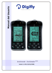
User manual Archimede - Archimede Version 1.3 UK (24/10/2008) plus CONGRATULATIONS Thank you for choosing Digifly! You have purchased a high technology instrument designed expressly for free flight. The multiple functions and flight data it provides, effectively make it an on board computer. Learning to use this instrument will make your flying easier in terms of performance and safety. It will enable you to improve your flying technique and make piloting decisions more quickly thanks to the comprehensive flight information that is provided. Another benefit is the ability to download and analyze your flight data afterwards. Our designers can foresee future software developments, so the software at the heart of this instrument can be updated at any time via the Internet using the optional Digifly PC cable. DIGIFLY INTERNATIONAL GUARANTEE Dear Customer, Thank you for purchasing this Digifly product which has been designed and manufactured to the highest quality standards. Digifly warrants this product to be free from defects in materials and workmanship for 3 years from the date of purchase. The Digifly guarantee applies provided the product is handled properly for its intended use, in accordance with its operating instructions and upon presentation of the original invoice or cash receipt, indicating the date of purchase, the dealer’s name, the model and the serial number of the instrument. The customer is however, responsible for any transportation costs. The unit must be securely packaged for return. The Digifly guarantee may not apply if: - The documents have been altered in any way or made illegible. - Repairs or product modifications and alterations have been executed by unauthorized person or service. - Damage is caused by accidents including but not limited to lightning, water or fire, misuse or neglect. Digifly assumes no responsibility for special, incidental, punitive or consequential damages, or loss of use. If your Digifly product is not working correctly or is defective, please contact your Digifly dealer. In order to avoid unnecessary inconvenience, we advise you to read the operating instructions carefully before contacting your dealer. Digifly Europe s.r.l. Via Stradelli Guelfi 53 40138 Bologna – Italia Tel. +39 051 533777 Internet: www.digifly.com E-Mail: [email protected] Page 2 1 INDEX 1 INDEX ............................................................................................................................................................... 3 2 GETTING STARTED .......................................................................................................................................... 6 2.1 GUIDE TO SOCKETS .....................................................................................................................................6 2.2 BATTERIES....................................................................................................................................................6 2.3 NORMAL OR LONG KEY PRESS ...................................................................................................................6 2.4 TURNING ON & OFF......................................................................................................................................6 2.5 DISPLAY CONTRAST ADJUSTMENT .............................................................................................................7 2.6 MENU NAVIGATION ......................................................................................................................................7 2.7 SETTING UP YOUR INSTRUMENT.................................................................................................................7 2.8 MULTI LANGUAGE HELP...............................................................................................................................8 2.9 RESTORE FACTORY SETTINGS ....................................................................................................................8 3 QUICK REFERENCE GUIDES............................................................................................................................ 9 3.1 BASIC DISPLAY .............................................................................................................................................9 3.2 ADVANCED DISPLAY.................................................................................................................................. 10 3.3 PLUS DISPLAY (ARCHIMEDE PLUS ONLY) ....................................................................................................... 11 4 DISPLAY .........................................................................................................................................................12 4.1 5 MAIN DISPLAY SCREENS .......................................................................................................................... 12 BASIC FUNCTIONS.........................................................................................................................................13 5.1 ALTIMETER ................................................................................................................................................ 13 5.1.1 BAROMETRIC ALTIMETER A1 .......................................................................................................... 13 5.1.2 BAROMETRIC ALTIMETER A2 .......................................................................................................... 13 5.1.3 BAROMETRIC ALTIMETER A3 .......................................................................................................... 13 5.1.4 ADJUSTING ALTIMETERS A1 A2 AND A3 ........................................................................................ 14 5.1.5 GRAPHIC ALTIMETER DISPLAY........................................................................................................ 14 5.2 VARIOMETER ............................................................................................................................................. 15 5.2.1 SUPERFAST INTELLIVARIO............................................................................................................... 15 5.2.2 VARIO REACTIVITY ............................................................................................................................ 15 5.2.3 ANALOGUE VARIO............................................................................................................................. 15 5.2.4 INTEGRATED (AVERAGED) VARIO.................................................................................................... 16 5.2.5 ACOUSTIC VARIO............................................................................................................................... 16 Page 3 5.2.6 5.3 VARIO SIMULATOR ........................................................................................................................... 16 AIR SPEED (WITH OPTIONAL AIR SPEED PROBE).................................................................................... 17 5.3.1 STALL ALARM ................................................................................................................................... 17 5.3.2 AIR SPEED RECALIBRATION ............................................................................................................ 17 5.4 TEMPERATURE.......................................................................................................................................... 18 5.5 BAROMETER.............................................................................................................................................. 18 5.6 TIME / CHRONOGRAPH............................................................................................................................. 18 5.7 PILOT NAME............................................................................................................................................... 18 5.8 GLIDER DATA (ARCHIMEDE PLUS ONLY)......................................................................................................... 18 6 ADVANCED FUNCTIONS ................................................................................................................................19 6.1 TOTAL ENERGY COMPENSATION ............................................................................................................. 19 6.2 THERMAL CENTERING FUNCTION (ARCHIMEDE PLUS ONLY)....................................................................... 19 6.3 AIR EFFICIENCY - GLIDE RATIO (ARCHIMEDE PLUS ONLY) ............................................................................. 20 6.4 POLAR DATA (ARCHIMEDE PLUS ONLY) .......................................................................................................... 20 6.5 SPEED TO FLY (ARCHIMEDE PLUS ONLY) ....................................................................................................... 21 6.6 MCCREADY (ARCHIMEDE PLUS ONLY) ............................................................................................................ 22 6.7 EQUIVALENT MCCREADY (ARCHIMEDE PLUS ONLY) ..................................................................................... 22 6.8 NETTO VARIO (ARCHIMEDE PLUS ONLY)........................................................................................................ 23 6.9 THERMAL SNIFFER (ARCHIMEDE PLUS ONLY).............................................................................................. 23 7 FLIGHT RECORDER........................................................................................................................................24 7.1 ACTIVATING THE FLIGHT RECORDER ....................................................................................................... 24 7.1.1 AUTOMATIC START RECORD MODE................................................................................................ 24 7.1.2 ALWAYS RECORD MODE (Archimede Plus only) ........................................................................... 24 7.1.3 RECORD MODE OFF (Archimede Plus only)................................................................................... 25 7.2 PEAK RECORDER (ARCHIMEDE) .................................................................................................................. 25 7.3 BAROGRAPH RECORDER (ARCHIMEDE PLUS ONLY)...................................................................................... 25 7.4 LOG BOOK MANAGEMENT........................................................................................................................ 26 7.5 FLIGHT PLAYBACK (ARCHIMEDE PLUS ONLY) ................................................................................................ 26 8 PC CONNECTION AND INTERFACE................................................................................................................27 8.1 CONNECTING WITH THE DIGIFLY VLTOOLS SOFTWARE.......................................................................... 27 8.2 CONNECTING WITH COMPEGPS, MAXPUNKTE, GPSDUMP SOFTWARE (ARCHIMEDE PLUS ONLY) ............ 28 8.3 FIRMWARE UPGRADE ............................................................................................................................... 29 Page 4 8.3.1 8.4 9 UPGRADE PROCESS......................................................................................................................... 29 PROBLEMS CONNECTING TO YOUR PC.................................................................................................... 31 APPENDIX ......................................................................................................................................................33 9.1 DIGIFLY STANDARD ACCESSORIES.......................................................................................................... 33 9.2 OPTIONAL ACCESSORIES.......................................................................................................................... 33 9.3 DIGIFLY TECHNICAL FEATURES................................................................................................................ 33 9.4 STANDARD FUNCTIONS ............................................................................................................................ 33 9.5 ADVANCED FUNCTIONS (ARCHIMEDE PLUS ONLY)........................................................................................ 34 9.6 GENERAL SPECIFICATIONS ...................................................................................................................... 34 9.7 MAIN SETUP PARAMETERS (ARCHIMEDE) .................................................................................................. 35 9.8 MAIN SETUP PARAMETERS (ARCHIMEDE PLUS) .......................................................................................... 36 9.9 ADVANCED SETUP (ADV-SETUP) PARAMETERS (ARCHIMEDE PLUS) .......................................................... 37 9.10 RESTORE FACTORY SETTINGS ................................................................................................................. 37 9.11 ADVANCED DISPLAY ............................................................................................................................... 38 9.12 PLUS DISPLAY (ARCHIMEDE PLUS ONLY) ....................................................................................................... 39 9.13 BASIC DISPLAY .......................................................................................................................................... 40 Page 5 2 GETTING STARTED 2.1 GUIDE TO SOCKETS 2.2 BATTERIES The Archimede and Archimede Plus model has only one non-rechargable 1.5 volt AA size battery. This battery is situated in the removable battery "slot" and can also be replaced with other 1.5 volt AA size batteries. To change this battery you will need a flatblade screwdriver to unscrew the battery cover on the rear of the vario. Rechargeable batteries can be used, though are not recommended because of their high self discharge rate (after 2 months they are completely discharged and useless). If using a rechargable backup battery, note that this battery is not recharged by the instrument but has to be removed and recharged externally by the user. The battery life is about 200 hours. 2.3 NORMAL OR LONG KEY PRESS The length of time a key is pressed on your Digifly instrument influences the functions available. For a normal key press, you must press the button for less than a second. For a long key press, you must keep the button pressed down for at least 2 seconds. When not specified, the key press is to be considered as a normal key press (less than a second). 2.4 TURNING ON & OFF To turn on your Digifly instrument, press the key at least for 4 seconds. To turn off your Digifly instrument, press the key at least for 4 seconds. After switching off your Digifly instrument, you must wait at least 5 seconds before you can turn it on again. This prevents unwanted operation e.g. during transit in your glider bag. After turning your Digifly instrument on, the first screen briefly shows the vario model, pilot name (if set), vario serial number, software version, date and time and battery voltage. Page 6 2.5 DISPLAY CONTRAST ADJUSTMENT The contrast of the Digifly instrument LCD display can be adjusted to suit ambient light conditions. To change the contrast of the display, go to (MAIN SETUP \ n. 1 CTRS), press the key (function “EDIT”) to go to the edit mode and then press the arrow keys , to increase or decrease the display contrast. 2.6 MENU NAVIGATION To navigate the menus on your Digifly instrument, go to the MENU page by pressing the key (function “men”). To return to the instrument’s main display, press the key (function “ESC”). From the “MENU” page, to select the sub-menus, move up and down using the arrow keys , and to confirm, press the key (function “ENT”). To change the selected parameter’s values, use the arrow keys with the the , and confirm key (function “SAV”) or you can also leave without saving your edit with key (function “ESC”). 2.7 SETTING UP YOUR INSTRUMENT To setup your Digifly instrument and adjust the parameters mentioned in the following sections, go to the MENU page by pressing the key (function “men”). There are two setup menus on the Digifly instrument. The “MAIN SETUP” menu and the “ADVANCED SETUP” menu (Archimede Plus only). Page 7 Using the arrow keys , scroll to select the “MAIN SETUP” or the “ADVANCED SETUP” menu and to select, confirm, press the key (function “ENT”). You will now see a list of parameters that can be adjusted in the “MAIN SETUP” menu or “ADVANCED SETUP” menu (Archimede Plus only). To change parameters, select the parameter you want to change, move up and down with the arrow keys , . Press the key (function “EDIT”) to go to the edit mode. To change the selected parameter’s values, use the arrow keys with the the , and confirm key (function “SAV”) or you can also leave without saving your edit with key (function “ESC”). To return to the instrument’s main display, press the key (function “ESC”). 2.8 MULTI LANGUAGE HELP To help you setup your Digifly instrument, the instrument supports several help languages. To change the help language go to (MAIN SETUP \ LANG) & select the language of choice 2.9 RESTORE FACTORY SETTINGS To restore the factory settings (default values for all parameters), press and hold down the key as you turn vario on. Keep the key pressed until a message “FACTORY SET?” appears, then confirm with “YES” or “NO”. If you select “YES”, a confirming message “SETUP RESET” is shown. Page 8 3 QUICK REFERENCE GUIDES 3.1 BASIC DISPLAY Altimeter A1 Analogue Vario Altimeter A2 / A3 Integrated Vario Air Efficiency (Plus) Air Speed / Pressure / Temperature Analogue Vario scale Time clock / Chronograph Volume Level - Flight Recorder - Battery State – Function Key (MENU) Graphic Altimeter / Thermal Centering (Plus) ● ● On / Off instrument ● ● Chronograph ● ● Zero Chronograph MENU Scroll Air Speed / Pressure / Temperature Time clock Scroll Page ● Volume Med / High ● ● Volume Off ● Scroll Altimeter A2 / A3 ● ● Zero Altimeter A2 / A3 Page 9 ● = Normal key pressure ● ● = Long key pressure (2 seconds) 3.2 ADVANCED DISPLAY Graphic Altimeter / Thermal Centering (Plus) Altimeter A1 Analogue Vario Altimeter A2 / A3 Integrated Vario Air Efficiency (Plus) Air Speed / Pressure / Temperature/ Time clock /Chronograph Analogue Vario scale Volume Level - Flight Recorder - Battery State – Function Key (MENU) Graphic Altimeter / Thermal Centering (Plus) ● ● On / Off instrument ● ● Chronograph ● ● Zero Chronograph MENU Scroll Air Speed / Pressure / Temperature Time clock Scroll Page ● Volume Med / High ● ● Volume Off ● Scroll Altimeter A2 / A3 ● ● Zero Altimeter A2 / A3 Page 10 ● = Normal key pressure ● ● = Long key pressure (2 seconds) 3.3 PLUS DISPLAY (Archimede Plus only) Graphic Altimeter / Thermal Centering (Plus) Altimeter A1 Equivalent McCready Altimeter A2 McCready Altimeter A3 height gain Analogue Vario Integrated Vario Netto Vario Analogue Vario scale Time Clock / Chronograph Air Efficiency (Plus) Air Speed / Pressure / Temperature Volume Level - Flight Recorder - Battery State – Function Key (MENU) Graphic Altimeter / Thermal Centering (Plus) ● ● On / Off instrument ● ● Chronograph ● ● Zero Chronograph MENU Scroll Air Speed / Pressure / Temperature Time clock Scroll Page ● Volume Med / High ● ● Volume Off ● Scroll Altimeter A2 / A3 ● ● Zero Altimeter A2 / A3 Page 11 ● = Normal key pressure ● ● = Long key pressure (2 seconds) 4 DISPLAY 4.1 MAIN DISPLAY SCREENS The are 3 main display screens on the Digifly Archimede Plus instrument and 2 main display screens on the Digifly Archimede instruments. - The Basic Display , the Advanced Display and the Plus Display. To switch between these main display screens, press the BASIC ADVANCED Page 12 key. PLUS 5 BASIC FUNCTIONS 5.1 ALTIMETER The Digifly instrument has 3 different altimeters: A1, A2, A3. - A1: Barometric Altimeter A1. - A2: Barometric Altimeter A2. - A3: Barometric Altimeter A3. The altimeters can be shown in metric (mt) or imperial (ft) units. To change the units of display, go to (MAIN SETUP \ U-AL). and change to “MT” or “FT”. 5.1.1 BAROMETRIC ALTIMETER A1 The altimeter A1 is the main barometric altimeter. 5.1.2 BAROMETRIC ALTIMETER A2 The barometric altimeter A2 is for generic use. To zero the A2 altimeter press the key (long press). To switch between the A2 or A3 altimeter, press the key. 5.1.3 BAROMETRIC ALTIMETER A3 In the Archimede the barometric altimeter A3 is for generic use and can be zeroed pressing the key (long press). In the Archimede Plus the A3 altimeter is automatically zeroed when a thermal is found. There are 2 parameters that can be adjusted to allow the Archimede Plus to identify a thermal; the vertical speed (vario) and for how many consecutive seconds this vertical speed is detected. To set the thermal detection parameters, go to (ADVANCED SETUP \ n. 1 THEV) and (ADVANCED SETUP \ n.2 THET) to adjust the vertical speed (vario) and for how many consecutive seconds this vertical speed is detected. To switch between the A2 or A3 altimeter, press the Page 13 key. 5.1.4 ADJUSTING ALTIMETERS A1 A2 AND A3 Go to the altimeter menu “ALTIM” and select which altimeter (A1 A2 or A3) you want to adjust. Move up and down using the arrow keys , and press the key (function “EDIT”). To adjust the altimeter value use the arrow keys , and confirm with the key (function “SAVE”) or leave without saving with the key (function “ESC”). To set the A1, A2 and A3 altimeters to standard QNH (1013mb), go to the altimeter menu “ALTIM” and select which altimeter (A1,A2 or A3) you want to adjust. Press the “central” key (long press). A confirmation of “YES” or “NO” is required. On the Archimede Plus is not possible to manually adjust the A3 altimeter because it is automatically zeroed when a thermal is found. 5.1.5 GRAPHIC ALTIMETER DISPLAY This is a live plot of your altitude against time (highlighted here in red), it scrolls whilst you are flying. It will help you to see how effectively you are climbing or turning in a thermal. It is especially useful in weak conditions. The scales on the graphic altimeter can be changed go to (MAIN SETUP \ n. 13 BARX and \n. 14 BARY). To switch between the graphic altimeter and the thermal centering display, press the key (Archimede Plus only). GRAPHIC ALTIMETER DISPLAY THERMAL CENTERING DISPLAY Page 14 5.2 VARIOMETER 5.2.1 SUPERFAST INTELLIVARIO The Intellivario is a revolutionary system designed by Digifly which is based on the use of sophisticated digital filters. This results in a very sensitive vario and is immune to radio interference. All the variometric functions are subject to these filters. The Digifly instrument has a very fast pressure sensor and an excellent data acquisition system that allows the instrument to perform as a very fast and accurate vario (updated 20 times a second). 5.2.2 VARIO REACTIVITY To adjust the reactivity of the vario, go to (MAIN SETUP \ n. 5 RVAR). The default setting is 0.4 sec. To increase the reactivity of the vario reduce the value of this parameter. For a more damped response, increase this value. 5.2.3 ANALOGUE VARIO The long data field on the left of the display shows the analogue vario value. The analogue vario is an instantaneous vario reading. This information is shown on the analogue display on the left of the screen by a bar graph, indicating lift or sink. The scale of the analogue vario can be adjusted to suit the conditions you are flying in. The default scale is 6m/s. To change the scale of the analogue vario, go to (MAIN SETUP \ n. 7 FS_V) and change the parameter from the default value “MED” (6m/s) to “HIGH” (12m/s), for very strong conditions or to “LOW” (1m/s) for very weak conditions. Page 15 5.2.4 INTEGRATED (AVERAGED) VARIO The integrated vario is an average vario reading. This time over which the reading is averaged is adjustable. The data in this display field is always “highlighted” to make reading in flight easier. You can change the integration interval by setting parameter (MAIN SETUP \ n. 6 INTE) between “0” and “60” seconds. It can be delayed or immediate. If you set a value that is too low, its value will be close to the instantaneous reading. Normally this is the most common setting. It can also be used for example to see if the rate of lift or sink is improving or getting worse. If the integrated vario reading over a number of seconds is higher than the actual reading, it means that you are doing worse than before. 5.2.5 ACOUSTIC VARIO The acoustic vario represents the instantaneous values of the vario with a modulated tone. The volume of the tone is adjustable over two levels “HIGH”and“LOW”, by pressing the key (long pressure). The volume level selected is shown by a change in the “speaker” graphic at the bottom of the screen To switch “OFF” the acoustic vario press the or key (long pressure). You can set the threshold level for the Digifly instrument to indicate lift, go to (MAIN SETUP \ n. 2 V.UP) and sink, go to (MAIN SETUP \ n. 3 V.DN). To change the vario tone based on your personal preferences, you can adjust the acoustic vario tone modulation, go to (MAIN SETUP \ n. 4 TONE). 5.2.6 VARIO SIMULATOR The vario simulator is very useful to check your acoustic vario settings without the need to test it in real flight. To activate the vario simulator go to (MAIN SETUP \ n. 8 SIMV) and select “ON”. Once in vario simulator mode is possible to change the vario value using the keys , . To deactivate the vario simulator go to (MAIN SETUP \ n. 8 SIMV) and select “OFF”. For safety reason the vario simulator is always turned off when you switch off the instrum. Page 16 5.3 AIR SPEED (WITH OPTIONAL AIR SPEED PROBE) The airspeed can be shown by the Digifly instrument. To display your air speed, you must have an air speed probe connected. The optional air speed probe should be plugged in to the right hand socket on the bottom of the vario. The air speed reading can be shown in metric (km/h) or imperial (mph) units. To change the units of display, go to (MAIN SETUP \ U-SP) and change to “KMH” or “MPH”. On the Archimede Plus the Air Efficiency “effist” is also displayed on the left side of the Air Speed indicator. To display the air speed press the key. 5.3.1 STALL ALARM To utilize the stall alarm function, you must have an air speed probe connected. The optional air speed probe should be plugged in to the right hand socket on the bottom of the vario. To enable the stall alarm select (MAIN SETUP \ n. 9 STAL) with a value higher than 0. The stall alarm is always disabled when the air speed drops lower than 5 km/h. 5.3.2 AIR SPEED RECALIBRATION If the air speed probe is showing inaccurate readings, it is possible to recalibrate the air speed probe, go to (MAIN SETUP \ n. 11 KIAS). An adjustment (in %) of the air speed reading can be made, (100%=no adjustment, 110%=increase, 90%=decrease). Incorrect recalibration will makes the air speed readings less accurate. Page 17 5.4 TEMPERATURE The temperature can be shown by the Digifly instrument. The ambient temperature reading can be shown in metric (°C) or imperial (°F) units. To change the units of display, go to (MAIN SETUP \ U-TE) and change to “CEL” or “FAR”. key. To display the temperature press the It is possible to adjust the temperature calibration, go to (MAIN SETUP \ KTMP). 5.5 BAROMETER The pressure can be shown by the Digifly instrument. To display the pressure press the key. It is possible to adjust the pressure calibration, go to (MAIN SETUP \ n. 12 KBAR). Incorrect recalibration will makes the barometric altimeter readings less accurate. 5.6 TIME / CHRONOGRAPH The time and chronograph information can be shown by the Digifly instrument. To show the time clock press the key. To show the chronograph press the key. To zero the chronograph, press the key (long press). To adjust the time and date, go to (MAIN SETUP \ n. 15 HOUR), (MAIN SETUP \ n. 16 MIN), (MAIN SETUP \ n. 17 DAY), (MAIN SETUP \ n. 18 MONT), (MAIN SETUP \ n. 19 YEAR). 5.7 PILOT NAME To set the pilot name go (MAIN SETUP \ PILO). 5.8 GLIDER DATA (Archimede Plus only) To set the glider type and the glider id go (MAIN SETUP \ GTYP), (MAIN SETUP \ GID). Page 18 6 ADVANCED FUNCTIONS 6.1 TOTAL ENERGY COMPENSATION Total energy compensation is the rate of change of atmospheric pressure and displays this as a vertical speed. If you slow down in flight, your glider will climb using the excessive kinetic energy. A “noncompensated” vario would interpret this as lift. Now, if you are flying quite fast and slow down when you enter a thermal, the vario reading gets rather difficult to interpret. Part of the lift reading is due to slowing down, and part is due to lift from the thermal. With total energy compensation, the part of the climb due to the change in velocity is ignored, allowing you to identify “real” thermals. To identify the correct total energy compensation value, an air speed probe must be connected to your vario. The optional air speed probe should be plugged in to the right hand socket on the bottom of the vario. To determine the correct total energy compensation value, with an air speed probe connected, you should fly in calm air conditions and slow down as if you are entering a thermal. If the vario shows a change in lift, you have to increase the total energy compensation value, go to (MAIN SETUP \ n. 10 TEC). Then try again until the change in velocity isn’t recorded as lift. A typical value for hang gliders is 65. The default setting of “0” deactivates the total energy compensation function. 6.2 THERMAL CENTERING FUNCTION (Archimede Plus only) This is a live plot of your vario against time, it scrolls whilst you are flying. It will help you to see how wide the thermal is and how far you flew from the best lift you encountered. It is especially useful in weak conditions. To switch between the Thermal Centering Function and the Graphic Altimeter press the key . The horizontal (x) scale, time (in minutes) can be changed, goto (MAIN SET\ n.13 BARX). The vertical scale (y), vario (in m/s) can also be adjusted, goto (MAIN SET \ n. 7 FS_V). Page 19 6.3 AIR EFFICIENCY - GLIDE RATIO (Archimede Plus only) To utilize the air efficiency functions you must have an air speed probe connected. The optional air speed probe should be plugged in to the right hand socket on the bottom of the vario. The air efficiency indicates the current efficiency (glide ratio) related to the air. The Air Efficiency “effist” is displayed on the left side of the Air Speed indicator. If Air Speed drops lower than 5km/h the display shows “- - -“. To adjust the time over which efficiency is averaged, go to (ADVANCED SETUP \ n. 3 EFF). To show the Air Efficiency – Air Speed dual indicator press the key. 6.4 POLAR DATA (Archimede Plus only) To utilize the polar data functions, you must have an air speed probe connected. The optional air speed probe should be plugged in to the right hand socket on the bottom of the vario. A polar curve (shown in bold on the figure) is a graph of your glider’s sink rate over its speed range. The glider’s stall speed is shown by at point S and the glider’s max speed at point T on the graph. On the graph, you can also see three pairs of relative speed readings and sink rates. At point A, you can see that the lowest sink rate achieved is at the top of the curve. Therefore SinkA is the minimum sink rate and VA is the speed at which this is achieved. The glide ratio is the ratio between the glider’s horizontal speed and the sink rate. To find the best glide rate on the graph, a straight line is from the origin of the graph (point O) to the tangent of the curve (point B). The speed to fly at to achieve the best glide (air related) is therefore VB and the glide ratio is VB/SinkB. On your instrument you can insert three different polars, go to (ADVANCED SETUP \ n. 6/14 PX-A/B/C) and choose which polar to use, go to (ADVANCED SETUP \ n. 5 POLA). Page 20 If this parameter (ADVANCED SETUP \ n. 5 POLA) is set to “OFF”, all information relating to McCready, McCready Equivalent, Thermal Sniffer is not displayed on the instrument, creating a cleaner display for users not needing this functionality. There are three polars preloaded, (2 for hang gliders and 1 for a paraglider). To see the three default polar curves and to calculate your own, use the Digifly Excel software available from the Digifly web site (www.digifly.com). We suggest that you insert your own polar curve data which best reflects the actual performance of your glider. 6.5 SPEED TO FLY (Archimede Plus only) To utilize the speed to fly functions you must have an air speed probe connected. The optional air speed probe should be plugged in to the right hand socket on the bottom of the vario. If this parameter (ADVANCED SETUP \ n. 5 POLA) is set to “OFF”, all information relating to McCready, McCready Equivalent, Thermal Sniffer is not displayed on the instrument, creating a cleaner display for users not needing this functionality. The speed to fly value is the optimum flying speed to obtain the best glide ratio. This value depends on performance of your glider as well as vertical and horizontal airflow. In calm air, the optimum flying speed is the same as the best glide speed (point B on the figure). On the figure above, you can see different values of speed to fly value related to different flight conditions. The X-axis shows horizontal speed, the Y-axis shows sink rate. In a head wind or sink conditions, the best glide speed increases. In order to find the optimum speed to fly value in sink, you simply add the sink of the air to the polar of your glider, drawing a new polar and a new tangent line from the initial point of axes. The new tangent (point D) meets the polar at the point giving a higher optimum flying speed VD. Page 21 To obtain the correct “Speed to fly” you Equiv. McCready have to adjust your speed so both McCready McCready arrows are in the same position. Optimal Good Bad - Speed to fly indications - 6.6 McCREADY (Archimede Plus only) To utilize the McCready functions, you must have an air speed McCready probe connected. The optional air speed probe should be plugged in to the right hand socket on the bottom of the vario. If this parameter (ADVANCED SETUP \ n. 5 POLA) is set to “OFF”, all display information relating to McCready, McCready Equivalent, Thermal Sniffer is not displayed on the instrument, creating a cleaner display for users not needing this functionality. The McCready value is the average lift value from last 10 minutes. The average time can be adjusted, go to (ADVANCED SETUP \ n. 15 MCRA). 6.7 EQUIVALENT McCREADY (Archimede Plus only) To utilize the McCready functions, you must have an air speed probe connected. The optional air speed probe should be Equivalent McCready plugged in to the right hand socket on the bottom of the vario. If this parameter (ADVANCED SETUP \ n. 5 POLA) is set to “OFF”, all display information relating to McCready, McCready Equivalent, Thermal Sniffer is not displayed on the instrument, creating a cleaner display for users not needing this functionality. This value indicates the Equivalent McCready value, using the actual air speed as the optimal speed. The Equivalent McCready indicator is a kind of "reverse" speed to fly calculation. It tells you that flying at the current air speed you are assuming that the average thermal value of the flight is the value indicated from the Equivalent McCready. To set the average of the Equivalent McCready, go to (ADVANCED SETUP \ n. 16 MCRE). Page 22 6.8 NETTO VARIO (Archimede Plus only) To utilize the netto vario function, you must have an air speed probe connected. The optional air speed probe should be plugged in to the right hand socket on the bottom of the vario. If this parameter (ADVANCED SETUP \ n. 5 POLA) is set to “OFF”, the netto display vario is disabled and all display information relating to McCready, McCready Equivalent, Thermal Sniffer is not displayed on the instrument, creating a cleaner display for users not needing this functionality. The netto vario indicates the vertical speed of the rising or sinking air mass you are flying through and is displayed with black digits with a white background (this allows it to be distinguished from the standard vario that is displayed in “reverse” mode). To use this function, you also need to set up the polar curve of your glider. 6.9 THERMAL SNIFFER (Archimede Plus only) To utilize the thermal sniffer function, you must have an air speed probe connected. The optional air speed probe should be plugged in to the right hand socket on the bottom of the vario. If this parameter (ADVANCED SETUP \ n. 5 POLA) is set to “OFF”, all display information relating to McCready, McCready Equivalent, Thermal Sniffer is not displayed on the instrument, creating a cleaner display for users not needing this functionality. The thermal sniffer is an innovative function that helps you to detect a thermal early. It alerts you with a sound and the popup message “THERMAL” when you are in a thermal but your vario is still indicating sink because your sink rate is higher than the speed of the rising air. This function uses two parameters, the thermal strength and the time over which the thermal must occur. To set the thermal detection parameters, go to (ADVANCED SETUP \ n. 2 THET) and (ADVANCED SETUP \ n. 1 THEV) to adjust the vertical speed (vario) and for how many consecutive seconds this vertical speed has to be detected. To use this function you need to set up the polar of your glider. Page 23 7 FLIGHT RECORDER When the Digifly instrument is recoding a flight, the record icon in shown at the bottom of the screen. In order to respect the FAI rules access to the “MAIN SETUP” menu on the Digifly Archimede Plus is blocked when the flight recorder has been activated. 7.1 ACTIVATING THE FLIGHT RECORDER The Archimede flight data recorder is always activated in automatic mode while the Archimede Plus can operate in 3 different modes: - “AUT” Automatic start record mode. - “ALW” Always record mode - “OFF” No data recording. 7.1.1 AUTOMATIC START RECORD MODE The default record mode is automatic start record mode, “AUT”, parameter (MAIN SETUP \ RECM). In the automatic start record mode it is possible to change the parameters that initiates the recording. You can adjust the change of height in meters (MAIN SETUP \ R.DS) required for the instrument to automatically start recording a flight In the automatic start record mode, the flight recorder will start on take off. The take off is detected when there is a change of height (lift or sink) greater than 2 meters (MAIN SETUP \ R.DS) over 4 seconds. e.g. MAIN SETUP \ R.DS = 2 means that a vertical speed (lift or sink) bigger than 0,5 m/s for at least 4 consecutive seconds is required to recognize a take off (0,5 x 4 = 2). In order to respect the FAI rules access to the “MAIN SETUP” menu on the Digifly Archimede Plus is blocked when the flight recorder has been activated Once the recorder is activated, the flight recorder will only stop recording when the instrument is turned off. 7.1.2 ALWAYS RECORD MODE (Archimede Plus only) In the Always record mode “ALW” (MAIN SETUP \ RECM) the flight data recorder starts recording 5 seconds after the instrument is turned on and stops recording when the instrument is turned off. In order to respect the FAI rules access to the “MAIN SETUP” menu on the Digifly Archimede Plus is blocked when the flight recorder has been activated Page 24 7.1.3 RECORD MODE OFF (Archimede Plus only) In the record mode “OFF” (MAIN SETUP \ RECM), no data is recorded. 7.2 PEAK RECORDER (Archimede) The peak recorder of the Archimede saves for each flight (for the last 50 flights): take off date and time, the duration of the flight and the total gain of altitude attained, the minimum and maximum values of altimeter A1, the variometer values and air speed. When the recorder memory is full, the oldest flight is automatically deleted. To delete all flights go to the “LOGBOOK” menu, press the “central” key (long press). A confirmation of “YES” or “NO” is required. 7.3 BAROGRAPH RECORDER (Archimede Plus only) The Barograph recorder of the Archimede Plus saves for each flight (for the last 250 flights): - Take off date and time, the duration of the flight and the total gain of altitude attained, the minimum and maximum values of altimeter A1, the variometer values and air speed. - It saves also continuously flight data points that includes altimeter A1, variometer and air speed at an adjustable record rate from 1 to 60 seconds, go to (MAIN SETUP \ RECR). At 1 data point per second you can record 28 hours of flight data. At 1 data point per minute, you can record up to 1680 hours of flight data. Up to 100,000 flight data points can be recorded from 250 flights. When the recorder memory is full, the oldest flight is automatically deleted. The remaining free recorder memory is displayed briefly as the instrument is turned on. If a single flight fills the whole memory, the recorder is stopped and the message “MEM FULL” is displayed ). To then record a new flight, it is necessary to clear the whole recorder memory. To delete all flights go to the “LOGBOOK” menu, press the “central “ key (long press). A confirmation of “YES” or “NO” is required. Page 25 7.4 LOG BOOK MANAGEMENT key (function “ENT”) To view saved flight data go to press the and select “LOGBOOK”. A list of all recorded flights with take off date and time is shown. To select which flight you want to view, move up and down using the arrow keys , and then press the key (function “ENT”). The first flight listed is the last recorded flight. To scroll to view the others flights navigate using Press the , keys key (function “ESC”) to return to the previous menu. To delete all flights from the flight log, from the “LOGBOOK” menu, press the ”central” key (long press). A confirmation of “YES” or “NO” is required. For each flight, the flight data screen includes the following information: Take off date and time, the duration of the flight and the total gain of altitude attained, the minimum and maximum values of altimeter A1, the variometer values and air speed. 7.5 FLIGHT PLAYBACK (Archimede Plus only) This is a special function that allows you to review (playback) on your vario the whole flight in detail. Moving the cursor on the graph you can read on the screen at each data point: Pressure altitude A1, variometer, air speed, time and chronograph values. To activate the playback function, press the key (function “MOV”). From this screen you can use these keys for the following functions: - Press the arrow keys , to zoom-in/zoom-out . - Press the arrow keys , to move the graphic cursor to the left or to the right. - Press the key (function “Tim”) to change the time display to chronograph display. Page 26 8 PC CONNECTION AND INTERFACE To download your flight data to your PC, plug the optional PC serial or USB cable into the middle socket on the base of your Digifly instrument. 8.1 CONNECTING WITH THE DIGIFLY VLTOOLS SOFTWARE The “VLTOOLS” software is a free Digifly Windows PC software that allows the full management of flight data recorder. Connect the PC cable with both the Digifly instrument and the PC switched off. Switch on the Digifly instrument and then the PC. From the Digifly instrument, go to the menu “VLTOOLS”, the message “LINK” start to flash. From your PC, run the latest Digifly VLtools software and click the “CONNECT” button. A successful connection is confirmed by a message with the serial number of your instrument For Archimede: Click the “Download All Flights” button to save all flights. At the end of the download the file “minmax.xls” will be created in the VLTOOLS directory. For Archimede Plus: Click the “Download Last Flight” or the “Download All Flights” button The “Download Last Flight” button will save last flight in two different file format flight.igc and flight.xls . The “Download All Flights” button will save each flight in two different formats (*.igc and *.xls) with file name 01, 02, 03 etc For Archimede and Archimede Plus: At the end of the download *.XLS and *.IGC files will be created in the VLTOOLS directory. Page 27 Note: these files will be always overwritten so it's very important that you rename them after the download. Files *.igc can be viewed on your PC with most IGC compatible software packages e.g. CompeGPS, MaxPunkte, GpsDump, Seeyou, Oziexplorer, etc. Files *.xls can be read & edited using Mircosoft Excel. For more info on all other functions read the Digifly VLTools user manual. 8.2 CONNECTING WITH COMPEGPS, MAXPUNKTE, GPSDUMP SOFTWARE (Archimede Plus only) The instrument can communicate via a direct cable connection with some of the commonly used competition software packages e.g. CompeGPS, MaxPunkte, GpsDump. With these programs is possible to download flight recorder in IGC format 1) To communicate with a PC connect the optional PC serial cable or USB cable in to the left socket on the bottom of the vario, marked GPS. 2) Enter the “LOGBOOK” menu on your instrument. 3) With up and down arrows, highlight the desired flight (without entering in it). 4) From the PC software (CompeGPS, MaxPunkte, GpsDump) select “download flight track” using the protocol MLR 38400 baud. Note.The download can be stopped pressing the “ESC” key on the your Digifly instrument. Page 28 8.3 FIRMWARE UPGRADE The software (firmware) on your Digifly instrument can be updated as new releases are made available from Digifly. This will allow your instrument to be kept up to date with new functions and improvements. The latest Digifly software may be downloaded from the Digifly web site (www.digifly.com) & installed using the optional PC serial or USB cable. The optional PC serial or Digifly USB cable is connected to the middle socket on the base of the Digifly instrument. When upgrading from Digifly instrument firmware version 44.0 (or older) to a new version all previously recorded flights will be erased and all settings will be restored to the factory default. 8.3.1 UPGRADE PROCESS Make sure the battery on your Digifly instrument is fully charged. Turn off your Digifly instrument and plug the Digifly PC serial or USB cable in to the middle socket on the base of the Digifly instrument. Keeping the key pressed, press the key and wait a long “beep” acoustic confirmation. Note that the screen will not come on. Now release the key and then the key. From your PC, run the “Upgrade_xx_x_Archimede.exe” program. Press the Start Button. Make sure you have only one version of the “Upgrade_xx_x_Archimede.exe” programme open at a time. When the “Upgrade_xx_x_Archimede.exe” tools software is operating you will see the progress of the software. Page 29 Upgrade take about 5 minutes , on completion the PC will confirm with a long “beep”. Press the key and disconnect the PC cable. When you restart your Digifly instrument the version number of the new software you have just installed is briefly shown on the start up screen. Page 30 8.4 PROBLEMS CONNECTING TO YOUR PC Problem: I attached the cable but the software does not connect. Solutions: A) Unplug the cable, download from our web site the driver installer (www.digifly.com >software -> " DIGIFLYNEXTGEN-USB Driver.zip”, run it on your PC then plug in the cable again. How to Check the Driver Installation: 1) Go to the Device Manager : Start -> Control Panel -> System -> Hardware -> Device Manager. 2) Click on the plus sign (+) next to "Ports". 3) If the device is installed properly, you will see "Prolific USB-to-Serial Com Port. (COMx)". Note that x is the number of the COM port assigned to the cable. B) Look for a conflict with a another program or device and turn off firewall / antivirus programs. C) It is also possible that the COM port number assigned is too high or duplicated with some other devices e.g. (Bluetooth - Irda). Try to reassign the COM port number (from 2 to 4): 1) Go to the Device Manager: Start ->Control Panel ->System ->Hardware ->Device Manager. 2) Click on the plus sign (+) next to "Ports". Page 31 3) Right click on the "Prolific USB to Serial Port" and click on Properties. 4) Click on the "Port Settings" tab. Click the "Advanced" button. 5) Pull down the scrollbar on the bottom, left side and select COM 2, 3 or 4 (NOTE: Choose one that does not say "in use" next to it). Click "OK". 6) Click "OK" again. Notice that the device will show up as being on the same COM port that it was before (i.e., COM5), but will show up on the new port if you close the Device Manager and open it again. D) From Windows, right click on the Vltools icon and tick the check box “run this program in Windows98/WindowsMe compatible mode”. Problem: The cable is working with the Digifly Vltools but not with the software I'm using. Solutions: Make sure that the software and the cable are using the same COM port number (try with the Digifly Vltools program to check the COM port number). If you are still experiencing problems try with the following: - Temporarily disable your antivirus and firewall software. - Manually setup on your PC the communication protocol MLR 38400 baud. - If this still fails, try adjusting the communication protocol to MLR 19200 baud. Page 32 9 APPENDIX 9.1 DIGIFLY STANDARD ACCESSORIES The Digifly Archimede and Archimede Plus has the following accessories provided as standard: Protective case. Leg strap. AA 1.5V alkaline battery. 9.2 OPTIONAL ACCESSORIES The following optional accessories are available from Digifly: Digifly PC serial cable to download flight data and upload new firmware directly from the Internet. Digifly PC USB cable to download flight data and upload new firmware directly from the Internet. Air speed probe for hang glider. Air speed probe for paraglider. Hang gliding vario mount. Paragliding vario mount. 9.3 DIGIFLY TECHNICAL FEATURES 9.4 STANDARD FUNCTIONS Graphic altimeter. Altimeters 9,000 m (29527 ft). Super fast vario with dynamic filter ‘IntelliVario . Acoustic vario with adjustable levels, volume and tone. Analogue vario +/- 24 m/s (4800 ft/min). Digital vario +/- 25 m/s (5000 ft/min). Vario integrator adjustable from 0 to 60 sec. Total energy compensation (with optional air speed probe). Input for optional air speed probe 150 km/h (93 mph) with user calibration. Adjustable stall alarm acoustic (with optional air speed probe). Barometer (range 300 to 1200 mB) with user calibration. Thermometer (range -30°C to +70°C) (range -22 °F to +158 °F). Constant battery monitoring. 50 flights data recorder with peak values and autostart (Archimede). 250 flights barographic continuous data recorder with 100.000 data points, autostart and Playback function (Archimede Plus only) Date and time, chronometer, flight timer. Adjustable units of measure. 8 Languages for help setup Page 33 9.5 ADVANCED FUNCTIONS (Archimede Plus only) 3 adjustable polar curves. McCready and Equivalent McReady function (with optional air speed probe). Speed To Fly (with optional air speed probe). Efficiency related to the air (with optional air speed probe). Netto Vario (with optional air speed probe). Thermal sniffer (with optional air speed probe). Thermal centering function. Auto zero thermal altimeter A3. 9.6 GENERAL SPECIFICATIONS High resolution graphic LCD display 128 x 64 pixels. Upgradeable Flash memory software available from the Internet using the optional PC cable via your PC. PC connection. Input for optional air speed probe. Battery life 200 hours with High Power AA 1.5V. Dimensions (H x L x D) 144mm x 72mm x 25mm. Weight (with battery) 180g . The Archimede and ArchimedePlus instruments are supplied with leg strap, protective case and AA 1,5V alkaline battery. 3 year warranty. Page 34 9.7 MAIN SETUP PARAMETERS (Archimede) The following is a list of parameters that can be adjusted. For each parameter you can see the range of values, the factory setting (default) and the unit of measure. n Name Description Range Default Units 1 2 3 4 5 6 7 8 9 10 11 12 13 14 15 16 17 18 19 20 21 22 23 24 25 26 CTRS V.UP V.DN TONE RVAR INTE FS_V SIMV STAL TEC KIAS KBAR BARX BARY HOUR MIN DAY MONT YEAR R.DS PILO U-AL U-SP U-TE KTMP LANG display contrast 40 - 60 50 % acoustic vario lift setting 0 - 25 0.05 m/s acoustic vario sink setting 0 - 25 3.5 m/s acoustic vario tone FAS/STD/SFT STD ---acoustic vario reactivity 0.1- 3.0 0.4 sec vario integrator 0 - 60 1 sec graphic vario scale (1,6,12) LOW/MED/HIGH MED m/s vario simulator ON/OFF OFF ---stall alarm level 0 - 150 0 km/h total energy compensation 0 - 100 0 % air speed calibration 50 - 200 100 % barometer calibration +/- 20.0 0 mB graphic altimeter x 0.4 - 4 1.0 min graphic altimeter y 3 - 3000 30 mt time setting: hours 0 - 23 ---hour time setting: minutes 0 - 59 ---minute time setting: day 1 – 31 ---day time setting: month 1 – 12 ---month time setting: year 0 – 99 ---year autorecorder meters 1 – 30 2 mt pilot name 6 letters ------altimeter units MT/FT MT ---speed units KMH/MPH KMH ---temperature units °C/°F °C ---temperature calibration +/- 20.0 0 °C help language USR/UK/ITA/ESP/DEU/FRA/CZE/HUN/LN1/LN2 Page 35 9.8 MAIN SETUP PARAMETERS (Archimede Plus) The following is a list of parameters that can be adjusted. For each parameter you can see the range of values, the factory setting (default) and the unit of measure. n Name Description Range Default Units 1 2 3 4 5 6 7 8 9 10 11 12 13 14 15 16 17 18 19 20 21 22 23 24 25 26 27 28 29 30 CTRS V.UP V.DN TONE RVAR INTE FS_V SIMV STAL TEC KIAS KBAR BARX BARY HOUR MIN DAY MONT YEAR PILO RECM R.DS RECR GTYP GID U-AL U-SP U-TE KTMP LANG display contrast 40 - 60 50 % acoustic vario lift setting 0 - 25 0.05 m/s acoustic vario sink setting 0 - 25 3.5 m/s acoustic vario tone FAS/STD/SFT STD ---acoustic vario reactivity 0.1- 3.0 0.4 sec vario integrator 0 - 60 1 sec graphic vario scale (1,6,12) LOW/MED/HIGH MED m/s vario simulator ON/OFF OFF ---stall alarm level 0 - 150 0 km/h total energy compensation 0 - 100 0 % air speed calibration 50 - 200 100 % barometer calibration +/- 20.0 0 mB graphic altimeter x 0.4 - 4 1.0 min graphic altimeter y 3 - 3000 30 mt time setting: hours 0 - 23 ---hour time setting: minutes 0 - 59 ---minute time setting: day 1 – 31 ---day time setting: month 1 – 12 ---month time setting: year 0 – 99 ---year pilot name 6 letters ------recorder mode AUT/ALW/OFF AUT ---autorecorder meters 1 – 30 2 mt recorder rate 1 - 60 1 sec glider type 6 letters ------glider id 6 letters ------altimeter units MT/FT MT ---speed units KMH/MPH KMH ---temperature units °C/°F °C ---temperature calibration +/- 20.0 0 °C help language USR/UK/ITA/ESP/DEU/FRA/CZE/HUN/LN1/LN2 Page 36 9.9 ADVANCED SETUP (ADV-SETUP) PARAMETERS (Archimede Plus) The following is a list of parameters that can be adjusted. For each parameter you can see the range of values, the factory setting (default) and the unit of measure. n Name Description Range Default Units 1 THEV 2 THET 3 EFF 4 TELE 5 POLA 6-7-8 9-10-11 12-13-14 15 MCRA 16 MCRE 9.10 thermal detect vario thres. thermal detect time thres. instant efficiency average not used active polar P1-A P1-B P1-C P2-A P2-B P2-C P3-A P3-B P3-C McCready average time McCready equiv average time 0 - 25 1 - 30 1-30 OFF OFF/P1/P2/P3 polar 1 coeff. polar 2 coeff. polar 3 coeff. 0.2 - 30 0.1 – 3 0.5 10 3 OFF OFF xxx xxx xxx 10 0.4 m/s sec sec ---------------min sec RESTORE FACTORY SETTINGS To restore the factory settings (default values for all parameters), press and hold down the key as you turn vario on. Keep the key pressed until a message “FACTORY SET?” appears, then confirm with “YES” or “NO”. If you select “YES”, a confirming message “SETUP RESET” is shown. Page 37 9.11 ADVANCED DISPLAY Graphic Altimeter / Thermal Centering (Plus) Altimeter A1 Analogue Vario Altimeter A2 / A3 Integrated Vario Air Efficiency (Plus) Air Speed / Pressure / Temperature/ Time clock /Chronograph Analogue Vario scale Volume Level - Flight Recorder - Battery State – Function Key (MENU) Graphic Altimeter / Thermal Centering (Plus) ● ● On / Off instrument ● ● Chronograph ● ● Zero Chronograph MENU Scroll Air Speed / Pressure / Temperature Time clock Scroll Page ● Volume Med / High ● ● Volume Off ● = Normal key pressure ● Scroll Altimeter A2 / A3 ● ● Zero Altimeter A2 / A3 ● ● =Page Long 38 key pressure (2 seconds) 9.12 PLUS DISPLAY (Archimede Plus only) Graphic Altimeter / Thermal Centering (Plus) Altimeter A1 Equivalent McCready Altimeter A2 McCready Altimeter A3 height gain Analogue Vario Integrated Vario Netto Vario Analogue Vario scale Time Clock / Chronograph Air Efficiency (Plus) Air Speed / Pressure / Temperature Volume Level - Flight Recorder - Battery State – Function Key (MENU) Graphic Altimeter / Thermal Centering (Plus) ● ● On / Off instrument ● ● Chronograph ● ● Zero Chronograph MENU Scroll Air Speed / Pressure / Temperature Time clock Scroll Page ● Volume Med / High ● ● Volume Off ● = Normal key pressure ● Scroll Altimeter A2 / A3 ● ● Zero Altimeter A2 / A3 Page 39 ● ● = Long key pressure (2 seconds) 9.13 BASIC DISPLAY Altimeter A1 Analogue Vario Altimeter A2 / A3 Integrated Vario Air Efficiency (Plus) Air Speed / Pressure / Temperature Analogue Vario scale Time clock / Chronograph Volume Level - Flight Recorder - Battery State – Function Key (MENU) Graphic Altimeter / Thermal Centering (Plus) ● ● On / Off instrument ● ● Chronograph ● ● Zero Chronograph MENU Scroll Air Speed / Pressure / Temperature Time clock Scroll Page ● Volume Med / High ● ● Volume Off ● = Normal key pressure ● Scroll Altimeter A2 / A3 ● ● Zero Altimeter A2 / A3 ● ● =Page Long 40 key pressure (2 seconds)