1
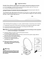
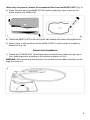
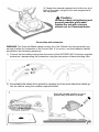
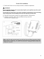
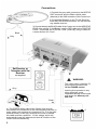
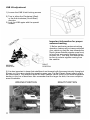
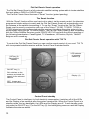
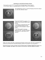
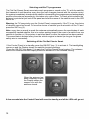
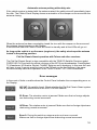
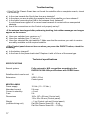
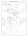
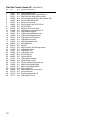
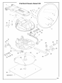
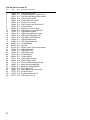
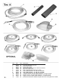
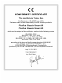
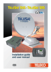
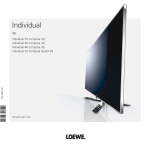
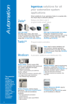
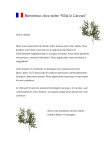
Installation guide
and user manual
GB
TELECO WARRANTY
Teleco guarantees its satellite dishes and terrestrial antennas against any
material and/or construction fault and defect. The warranty offered by TELECO
is limited to the free-of-charge replacement or repairing of any parts that are
deemed faulty by TELECO. The warranty is applicable for a period of 3
YEARS starting from the product purchase date; however, it will only be
considered valid if the Customer is able to produce a written document
(invoice or tax receipt) showing the purchase date.
The following is excluded from the TELECO warranty:
a. Damages caused by incorrect installation and/or use and/or maintenance
b. Damages resulting from product alterations not authorised by Teleco
c. Damages resulting from the use of spare parts different from original
Teleco parts
d. Damages resulting from repairs carried out by personnel not
authorised by Teleco
e. Normal part wear;
f. Expenses incurred for spare parts transport between the Customer's
and the service centre
g. Damages that may occur during transport:
the Customer shall always be responsible for transport risks.
Information
Congratulations on your purchase! Flat Sat Classic Smart is among the most technologically
advanced products in the field of satellite TV reception. This handbook has been prepared
to provide information on how to install, use, maintain and technical specifications your Flat
Sat Classic Smart.
For additional information, please contact your local dealer or directly the manufacturers:
TELECO s.p.a.
Via E. Majorana 49
48022 LUGO (RA)
Web site: www.telecogroup.com
Technical attendance: 899.899.856
TELECO .p.a. declines all responsibility for any errors contained in this manual. All the
contained information are up to the dates of printing and of the above-mentioned software
revisions. TELECO .p.a. reserves the right to introduce any modification made necessary by
the development of its products.
1
TABLE OF CONTENTS
Page
Information.............................................................................................................................1
List of accessories .................................................................................................................3
Installation of dish on motor unit............................................................................................4
Assembly instructions ............................................................................................................5
Control Unit Installation..........................................................................................................8
Connections...........................................................................................................................9
LNB rotation.........................................................................................................................10
Tips on the best use of Flat Sat Classic Smart....................................................................12
The Smart function ..............................................................................................................13
Troubleshooting ...................................................................................................................17
Technical specifications .......................................................................................................17
Spare Parts Table ................................................................................................................18
Recycling: with a view to reducing disposal of waste electrical and electronic
equipment as much as possible, do not throw out this end of life appliance together
with other unsorted municipal waste, but make use of a recycling centre.
2
List of accessories
Flat Sat Classic Smart is delivered inside a cardboard case that has been specially made
to protect it from knocks and pressure. The following accessories are supplied:
1
2
3
3
4
5
6
7
8
9
10
11
12
13
14
15
3
External motor-driven unit
65 - 85 cm dish
Universal LNB
SKEW (OPTIONAL)
Control unit
Wall-mounted Control panel
Motor connecting cable extension
Coaxial cable extension for antenna signal
Power Supply Cable
Control unit/Control panel connection cable
Waterproof box to pass leads through to interior
Heat-shrinking sheaths
Roof attachment plate
No. 4 Locknuts M6
No. 4 Screws and Locknuts – M6
User’s manual
Important notice
Flat Sat Classic Smart is packaged in two separate cartons for transport reasons:
a) the first package contains the driving unit with all the cables, and the Control unit.
b) the second package only contains the dish.
• It is important to check that the dish has not been damaged during transport when the
package is opened. In particular, check the following well:
• By resting the dish edge against a flat surface (e.g. the floor or a wall) check that it makes
contact to the surface all around. If it is not so, try and make the edge level, without denting
the dish, or call our After-Sales Service.
YES
NO
• After checking that everything is in order, install the dish on the driving unit as follows:
1) Temporarily connect the Control unit to the driving unit through the grey motor cable.
2) Connect the Control panel to the Control unit through the RJ45 cable.
3) Power the Control unit using a battery.
Warning: For correct connection of the wiring and to prevent damage to the equipment
please consult page 9 “Connections”.
4) Press the switch-on button on the Control panel and wait
for the dish support mast to rise.
5) Once you have reached the desired position, disconnect the power supply cable to
switch off the Flat Sat Classic Smart.
6) Secure the dish to the mast and screw
down the four supplied screws.
7) Turn the unit on again and wait for
the antenna to close.
8) Disconnect the the Control unit,
the battery and install the driving
unit on the vehicle
Warning:
NEVER loosen the two dish arm lock
screws (A) to attach the dish as this
will result in loss of alignment with
the antenna.
4
Assembly instructions
1) On the roof of the vehicle, choose a free area large enough to allow the antenna to
revolve (Fig. 2).
Driving direction
of the vehicle
Flat Sat Classic Smart 65 - 140 cm
Flat Sat Classic Smart 85 - 160 cm
4) Clean the roof carefully in the area the OUTSIDE UNIT is to be installed in.
3) Remembering that the OUTSIDE UNIT must be fastened as shown on Fig. 3, position
the base plate as shown on Fig. 4, with the short side towards the driving direction
of the vehicle.
Driving direction
of the vehicle
Driving direction
of the vehicle
5
When they are present, remove the transparent films from the BASE PLATE (Fig. 5).
4) Clean the lower part of the BASE PLATE carefully, applying a layer of glue on the
whole surface (e.g. SIKAFLEX).
5) Fasten the BASE PLATE to the roof (short side towards the vehicle driving direction).
6) Apply a layer of silicone all around the BASE PLATE in order to make it completely
waterproof (Fig. 5A)
Outside Unit Installation
1) Fasten the OUTSIDE UNIT on the base plate and lead the two cables through any of
the 4 existing grooves, according to the position as shown on Fig. 6.
WARNING: When performing this operation, do not draw the two cables forcefully, as this
might pull them out.
6
2) Fasten the external powered unit to the four stud
bolts of the plate, using the four nuts supplied with
the equipment.
Caution:
to ensure ideal nut tightening and
prevent possible pin breaks,
tighten the nut with a torque
wrench set to 8 Newtons/metre
Connection with extension
WARNING The Grey and Black cables coming out of the Outside Unit are generally long
enough to allow for connection to the Control unit. If it is not so, use the extension cables
and perform the following operations:
1) Connect the two cables coming from the centre of the OUTSIDE UNIT to the two supplied
extensions, waterproofing the connectors using the two pieces of heat-shrinking tube.
3) Accomodate the cables into a protection raceway up to the point where the cables go
into the vehicle, using the suitable supplied fairlead.
Seal the fairlead carefully so as to
prevent any infiltration by water
7
Control Unit Installation
1) Position the Control unit in an easy accessible, ventilated compartment.
WARNING:
Do not install the Control unit in areas where liquids can be spilled, since this could
cause irreparable damage.
Do not install the Control unit in very small, unventilated compartments, since overheating
could compromise its functionality and render the warranty null and void.
2) Place the Control panel comando in an easily accessible, visible position.
3) Install the connection cables (Grey and Black) until you reach the
OUTSIDE UNIT installation area.
Control Unit
Control Panel
Note: Install the wall-mounted control unit with the (Grey and Black) connection cables
bent as shown in the picture. This installation tip will prevent any condensation water from
flowing down the cables into your control unit electronics - damaging it beyond repair and
voiding your warranty.
8
Connections
1) Connect the grey cable (motors) to the MOTOR
UNIT connector and the Black coaxial cable
(antenna) to the LNB connector of the Control unit.
2) Connect the Receiver or the TV with Receiver
to the SAT RECEIVER connector. You can connect
any satellite receiver.
Black
3) Connect directly the BLACK cable of the Control unit to the NEGATIVE
POLE of the vehicle 12 Volt Battery, and the RED cable to the POSITIVE
POLE + (remember not to mix the + and - poles up), using 2 cables of
a cross section of 2.5 mm².
Grey
Sat Receiver or
Television with Sat
Receiver
not supplied
WARNING:
The 3-way power connector (P)
must only be inserted in the
12 Vac POWER socket.
Grey
Inserting this connector in any
other socket will cause
irreparable damage to the board
and render the warranty null
and void.
Green
4) The GREEN safety cable of the Control Unit must be
connected to the consensus of the vehicle startup console (in
many cases such consensus is located on Pin 15 in the main
terminal board). In this way, whenever the motor is started,
this cable receives a positive + 12 Vdc voltage, which will
automatically lower the antenna and lock all functions of the
Control Unit simultaneously.
9
WARNING
This technical note is to call the attention of the installation personnel to certain details
of Flat Sat Classic Smart installation. During installation, you must take the following
precautions:
The power supply cable must directly come from the battery and must have no junctions.
Minimum cross section of the cable is 2,5 mm2. For cable lengths equal to or above 6 metres,
the minimum cross-section is 4 mm2. Only the Flat Sat Classic Smart must be connected to
this cable; all the other devices must be connected to another power supply cable.
The cable connecting the driving unit to the Flat Sat Classic Smart Control unit must NEVER
be cut for any reason whatsoever: should the cable turn out to be too long, wind the extra
part into a coil in a free area of the vehicle. Leave a little cable in the driving unit area; should
any technical operation be required, it will make it easier to remove the driving unit.
Failure to observe these instructions shall render the Warranty null and void.
LNB rotation for ideal signal reception in extreme
(South-western or South-eastern) areas in Europe
Please be reminded that your outside low-noise block converter (LNB) has its own special
mounting position that must be maintained, otherwise you will be unable to receive any
signals. The LNB pre-defined installation position is along the dish centre line (Fig. A): in this
configuration, the Flat Sat Classic Smart system will operate correctly in most European
countries. If, however, you happen to find yourselves very far from the orbital position of your
required satellite, you may want to adjust your low-noise block converter angle. This is
especially true if you wish to receive satellite signals from Astra 19E, Astra 28E or HotBird
13E and you are in Portugal or Morocco: you will then have to adjust the LNB angle as shown
in fig. B, while if you happen to be in Turkey, to receive signals from the same satellites you
will have to adjust your LNB to the position shown in fig. C.
Place
Position
HotBird 13E
Astra 19E
Astra 28E
Lisbona
Casablanca
Ankara
B
B
C
25°
27°
22°
28°
34°
15°
37°
41°
5°
10
LNB tilt adjustment
1) Loosen the LNB U-bolt locking screws
2) Turn in either the Clockwise (West)
or the Anti-clockwise (South-East)
direction
3) Lock the LNB again with the special
screws
Important information for proper
antenna tracking
1) Before performing antenna tracking
operation, make sure you have positioned
your vehicle so that the view towards the
South (where Satellite signals come from)
is free from any nearby obstacle (trees,
houses, etc.). This way, the antenna will
be free to receive signals coming from
the satellite.
RIGHT
POSITION
WRONG
POSITION
2) It is also important to know that satellites do not transmit with the same intensity throughout
Europe, so if you are outside the reception area, your Flat Sat Classic Smart search might
be unsuccessful. The reception areas for each Satellite can be found on the main magazines
dealing in this line of business. Also remember that the larger the dish, the more reception
area is available.
WRONG POSITION
11
RIGHT POSITION
Tips on the best use of Flat Sat Classic Smart
When you park your vehicle, make sure that:
1) No obstacle (for example trees) is too near your antenna, preventing it from moving
freely. No metal or glass wall is very near (about 5 m) the antenna, since this would
act as a mirror for satellite signals and could induce the antenna to stop towards it.
2) Remove any snow or ice from the Flat Sat Classic Smart before actuating it in order
to avoid wasting battery power trying to lift it.
3) If you decide to turn the engine of your vehicle on in order to re-charge its batteries,
with the safety cable connected to the ignition key, the antenna, if lifted, will come
down automatically and it will not be possible to lift it again as long as the engine is
running.
4) Make sure that your batteries are always sufficiently charged, since, if the voltage
falls below 10 Volts, the Flat Sat Classic Smart electronic safety circuit will prevent
the antenna from rising.
5) Should you use 12 Volt power supply instead of batteries, be careful to use stabilized
power supply being able to provide 5 A continuously and at least 10 A for short periods.
At all costs, avoid using low quality, non stabilized battery chargers.
6) It is recommended not to use the antenna under strong wind conditions
(80 km/h). Failure to comply with this condition may result in product degradation
which the manufacturer cannot be held responsible for.
7) Antenna closing operations, whether by user's control or automatically for
vehicle start-up, require variable time.
Before starting the vehicle, always make sure that the antenna is fully closed.
*
The manufacturer declines any liability for all degradations suffered by the
product owing to misuse.
12
Flat Sat Classic Smart operation
The Flat Sat Classic Smart is a fully automatic satellite tracking system able to locate satellites
that emit either a DVB-S or DVB-S2 signal.
The Flat Sat Classic Smart features a “Smart” function (patent pending).
The Smart function
With the “Smart” function all the user has to do is select, via the remote control, the television
programme he/she wishes to watch and the Flat Sat Classic Smart will automatically point
the antenna at the satellite transmitting it. To use the “Smart” function the Flat Sat Classic
Smart must be used in conjunction with one of the Teleco TY2/19D, TY2/22D, TY2/24 or
TY2/32 televisions with incorporated satellite receiver; this allows the entire system to be
piloted simply using just the TV remote control. The Flat Sat Classic Smart is also compatible
with the Teleco Satellite Receiver model FORCE HD CI+D and with the official receivers of
the following broadcasters: CanalDigitaal, TV Vlaanderen, HD Austria, Skylink, TéléSAT
Belgium and Luxemburg.
Flat Sat Classic Smart operation with TY2 TV
To control the Flat Sat Classic Smart you can use the remote control of your mod. TY2 TV
with incorporated satellite receiver and the Control Panel illustrated below.
LED indicator
of selected
satellite (4)
SAT key (2)
Selecting the
satellite
ON-OFF key (1)
ON: switches on the
antenna and starts the
search for the selected
satellite.
Display (3)
OFF: Lowers and
switches off the antenna
Control Panel standby
The Control Panel is intelligent: to limit electricity consumption it switches off all the LEDs
and the Display a few seconds after the system remains idle. When the Control Panel is in
standby mode, the key backlights, the LEDs and the Display are off. To exit standby mode
just press the ON-OFF key (1) or the SAT key (2): the backlighting comes on and the Display
indicates the antenna status.
13
Switching on the Flat Sat Classic Smart
First switch on the TY2 TV and then the Flat Sat Classic Smart system.
If the Control Panel is in standby press the ON/OFF key (1) to activate it.
The backlighting comes on and the Display shows the camper
icon with the antenna closed.
Press the ON-OFF key again (1) to
switch on the Flat Sat Classic Smart
system.
The Display (3) alternates the name
of the selected satellite and an
animation of the antenna in search
mode.
The “Moving dish” message
appears on the TV screen to indicate
the antenna is searching for the
satellite
When the search has been completed the Display (3) shows the “SAT OK” message; the
antenna is pointed at the selected satellite and the TV shows the set programme.
During the search, after a certain time the “Moving dish” message disappears and the “No
signal” message may appear; this remains on the screen until the satellite is located.
14
Selecting satellite TV programmes
The Flat Sat Classic Smart associates each programme, saved on the TV, with the satellite
that transmits it and therefore every time the user changes channel with the remote control
the system immediately checks which satellite is transmitting the programme and automatically
positions the antenna accordingly; this takes only a short time. To check which satellite the
antenna is pointed at just look at the panel and read the name of the satellite next to the LED
that is on.
Warning: the TV has priority over the Control Panel; consequently, if the TV is on, the choice
of channel cannot be forced. To force the choice of satellite you must switch off the TV and
press the SAT key (2).
Note: every time a search is made the antenna automatically saves the coordinates of each
successfully tracked satellite; this is to reduce waiting times in the event of a switch from one
satellite to another or if the system is switched back on after the antenna has been parked.
This saved data is deleted every time the vehicle engine is started (as long as the green
safety wire is connected).
Switching off the Flat Sat Classic Smart
If the Control Panel is in standby press the ON/OFF key (1) to activate it. The backlighting
comes on and the Display shows the satellite located message.
Press the ON-OFF key again (1) to park the Flat Sat Classic Smart system. The antenna
starts to be lowered and the Display shows an animation of the antenna closing.
When the antenna has
been completely closed
the Display shows the
camper icon with the
antenna closed.
A few seconds later the Control Panel will revert to standby and all the LEDs will go out.
15
Automatic antenna parking with safety wire
If the vehicle engine is started with the antenna raised, the safety wire will immediately lower
the dish. The Control Panel Display shows an animation of the camper on the move with the
antenna closing.
When the antenna has been completely closed the icon with the camper on the move and
the antenna closed remains on the Display.
A few seconds later the Control Panel will revert to standby and all the LEDs will go out.
As long as the vehicle is on the move (engine on), the safety wire keeps the antenna
locked in the parking position.
Flat Sat Classic Smart operation with Teleco and other receivers
The Flat Sat Classic Smart is also compatible with the TELECO Satellite Receiver model
FORCE HD CI+D and with the official receivers of the M7 Group broadcasters: CanalDigitaal,
TV Vlaanderen, HD Austria, Skylink, TéléSAT Belgium and Luxemburg. In this case the user
will have to use 2 remote controls (one for the TV and one for the Receiver); the same
functions already seen with operation of the TELECO mod TY2 TV will be available.
Error messages
In the event of faults or malfunctions the Control Panel indicates the corresponding error on
the Display:
NO SAT: No satellite found. Check whether the Flat Sat Classic Smart system
has any obstructions to the SOUTH of the Satellite.
EL Error: The elevation motor is jammed. Make sure that no foreign objects
are obstructing normal movement
AZ Error: The rotation motor is jammed. Make sure that no foreign objects are
obstructing normal movement
Error 9: During the switch-on stage a motor unit error occurred.
Make sure that no foreign objects are obstructing normal movement
16
Troubleshooting
• If the Flat Sat Classic Smart has not found the satellite after a complete search, check
the following:
a) Is the view towards the South free from any obstacle?
b) Is the place you are at within the reception area of the satellite you have chosen?
c) Is the cable connecting the LNB to the antenna firmly fastened?
It could have been ripped off or come loose because of contact with an unexpected
obstacle.
d) Are all the connections on the Control unit properly set up?
• If the antenna has stopped after performing tracking, but neither messages nor images
appear on the screen:
a) Have you switched your receiver on ?
b) Have you switched your TV set on ?
c) Have you selected the right satellite ? Make sure that the services you wish to receive
are really available on the required satellite.
• If the Control panel does not turn on when you press the ON/OFF button, check the
following:
a) Is the battery charged?
b) Is the fuse on the power lead intact? Replace it with a 5A one of the same type.
Technical specifications
SPECIFICATIONS
Search system
Fully automatic, NID recognition according to the
DVB-SI EN 300 468 specifications with DVBS2 tuner.
Satellites which can be set
Extensions
10
USB 1.0 Port
Control panel
MISCELLANEA
Power supply
Absorbed current
Current in stand-by
Fuse
Dimensions
Weight
(outside driving unit)
17
12 Vdc ( 10 - 15 Vdc )
5 A max.
< 5 mA
5A
160 x 187 x 58 mm (Control unit)
119 x 22 x 60 mm (Control panel)
~ 1 kg (Control unit and Control panel)
Flat Sat Classic Smart 65: ~ 9 kg.
Flat Sat Classic Smart 85: ~ 10,8 kg
Flat Sat Classic Smart 65
18
Flat Sat Classic Smart 65
(28/09/2015)
Pos
Cod
Q.ta
Description Dèsignation
1
2
3
4
5
6
7
8
9
10
11
13
14
15
16
17
18
19
20
21
22
23
24
25
26
28
29
30
31
32
33
34
35
36
11491
10487
15531
03685
10425
10533
10442
11088
10534
10384
11195
10543
10544
13316
10902
10903
03682
09015
01274
11425
16703
10283
11087
09014
11431
03684
11162
10693
10395
15616
10490
10779
10778
10777
N.1
N.1
N.1
N.4
N.4
N.1
N.2
N.1
N.1
N.1
N.1
N.1
N.1
N.2
N.1
N.1
N.1
N.3
N.2
N.1
N.1
N.1
N.2
N.2
N.1
N.4
N.1
N.1
N.1
N.4
N.2
N.2
N.2
N.2
Dish support mast
Parabolic antenna D=63.5x59 cm
Flat Sat Easy Smart Dish sticker
Self-locking nut M5 Flat Sat Classic S65
Screw M5X10 Flat Sat
External unit cover
Self-locking rivet SR-5105-W
Screw M4x8
External unit cover door
Self-tapping screw M2.9x9.5
LNB rubber support
LNB mast right-hand insert
LNB mast left-hand insert
Flat washer D22x30x0,5
LNB left-hand mast
LNB right-hand mast
Screw M5x40
Nut M5
White 10x2.5 self-locking clamp
LNB holder tube
LNB Stark TS1
LNB stop U-bolt
Screw M4x16
Screw M5x30
LNB support bottom
Self-locking nut M6
Plastic cable-locking split pin
Base fixing 45x40 plate
Base fixing 60x60 plate
Flat washer D5
Black plastic nut cover M10
Screw M10x35
Toothed washer D=10
Flat washer D=10
19
Flat Sat Classic Smart 85
20
Flat Sat Classic Smart 85
Pos
Code
Q.ta
Description Dèsignation
1
2
3
4
5
6
7
8
9
10
11
13
14
15
16
17
18
19
20
21
22
23
24
25
26
28
29
30
31
32
33
34
35
36
11440
10488
15531
03684
10910
10533
10442
11008
10534
10384
11195
10531
10532
13316
10902
10903
03682
09015
01274
11436
16703
10283
11087
09014
11431
03684
11162
10693
10395
15617
10490
10779
10778
10777
N.1
N.1
N.1
N.4
N.4
N.1
N.2
N.1
N.1
N.1
N.1
N.1
N.1
N.2
N.1
N.1
N.1
N.3
N.2
N.1
N.1
N.1
N.2
N.2
N.1
N.4
N.1
N.1
N.1
N.4
N.2
N.2
N.2
N.2
Dish support mast
Parabolic antenna D=85x78 cm
Flat Sat Easy Smart Dish sticker
Self-locking nut M6
Screw M6X12 Flat Sat
External unit cover
Self-locking rivet SR-5105-W
Hole grommet
External unit cover door
Self-tapping screw M2.9x9.5
LNB rubber support
LNB mast right-hand insert
LNB mast left-hand insert
Flat washer D22x30x0,5
LNB left-hand mast
LNB right-hand mast
Screw M5x40
Nut M5
White 10x2.5 self-locking clamp
LNB holder tube
LNB Stark TS1
LNB stop U-bolt
Screw M4x16
Screw M5x30
LNB support bottom
Self-locking nut M6
Plastic cable-locking split pin
Base fixing 45x40 plate
Base fixing 60x60 plate
Flat washer D6
Black plastic nut cover M10
Screw M10x35
Toothed washer D=10
Flat washer D=10
21
22
TAV. 2
Pos
Cod
Q.ta
Description
1
2
3
4
5
6
7
8
10
11
11161
04761
05086
06817
11088
12945
05807
12294
03280
15077
N.2
N.2
N.4
N.4
N.2
N.1
mt. 3,6
N.1
N.1
N.2
Electric motor
Waterproof microswitch
Screw M3x20
Flat washer D=3
Screw M4x8
Connector strip
Coax cable RG 58
10-pole 2.5 m Motor cable + PG21 x 2 cables
FF13 double female jack
F50 F connector
23
Pos
Cod
Q.ta Description
1
2
3
4
5
6
7
8
9
15963
15964
09835
15860
16553
09705
01458
11742
09318
N.1
N.1
N.4
N.1
N.1
N.1
N.4
N.1
N.1
Control unit lid smart
Control unit bottom smart
Black rubber foot
Control panel
T0215 board smart
5A Fuse
Support
PATCH UTP Cable
Power supply cable
24
25
Pos
Cod
Q.ta Description
1
2
3
4
5
6
7
8
9
10
11
12
13
05950
03598
03597
09300
10969
13190
07883
08998
07294
09765
09302
09301
11109
N.1
N.1
N.1
N.1
N.1
N.1
N.1
N.1
N.1
N.1
N.1
N.1
N.1
3 m coax cable F/F.connector
Shrink-wrap sheath
Shrink-wrap sheath
10-core 3 m engine unit cont. cable w/connector
White abs cable cover
PG21 complete with gasket for 2 cables
Coax cable extension - 9 m with F/F.connector
Coax cable extension - 2 m with F/F.connector
Coax cable extension - 5 m with F/F.connector
1 Engine connect 4+6 pole cable extension - 2 m with connect.
Engine connect 4+6 pole cable extension - 9 m with connect.
Engine connect 4+6 pole cable extension - 5 m with connect.
professional aluminium fairlead complete with PG 21 with gasket for 2 cables
CONFORMITY CERTIFICATE
The manifacturer Teleco Spa
Via Majorana nr. 49, 48022 Lugo ( RA )
Declares under its own responsibility that the following products:
Flat Sat Classic Smart 65
Flat Sat Classic Smart 85
which are the subject of this certificate, conform to the following norms:
EN 60065: 2002
EN 55013: 2001 + A1: 2003
EN 61000 – 3 - 2: 2000 + A2: 2005
EN 61000 – 3 – 3: 1995 + A1: 2001 + A2: 2005
EN 55020: 2002 + A2: 2005
according to the terms of the European directive 2006/95/EC
Low Voltage ( modified by 93/68/CEE ) and
2004/108/CEE of Electromagnetic Compatibility
(modified by 92/31/CEE e 93/68/CEE ) of the European Parliament.
Lugo 31 / 08 / 2015
THE PRESIDENT
Ing. Raul Fabbri
26_09_15