1
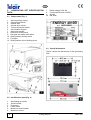
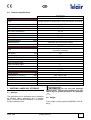
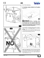
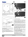
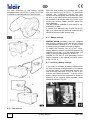
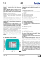
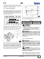
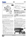
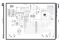
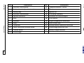
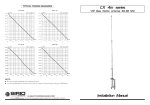
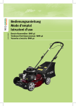
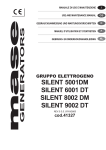
GB
GENERATORS
ENERGY 4010B
USER'S OPERATING INSTRUCTION
AND INSTALLATION MANUAL
GB
INDEX
1
Energy 4010 B
v. 002 – January 2015
Vers. 022
GB
INDEX
1 FOREWORD ................................................................................................................................... 5
1.1 Purpose and scope of this manual ............................................................................................ 5
1.2 Symbols and Definitions............................................................................................................ 5
1.3 General Information .................................................................................................................. 5
2 GENERATING SET IDENTIFICATION DATA ................................................................................. 6
2.1 Components (Fig. 1) ................................................................................................................. 6
2.2 Identification plate (Fig. 2) ......................................................................................................... 6
2.3 Overall dimensions ................................................................................................................... 6
2.4 Technical specifications ............................................................................................................ 7
3 SHIPPING, HANDLING, STORAGE ............................................................................................... 7
3.1 Storage ..................................................................................................................................... 7
3.2 Weight ...................................................................................................................................... 7
3.3 Handling ................................................................................................................................... 8
4 INSTALLATION .............................................................................................................................. 8
4.1 Preliminary information ............................................................................................................. 8
4.2 Instructions for fastening the generating set .............................................................................. 8
4.2.1 Hanging assembly.............................................................................................................. 8
4.2.2 Floor fastening .................................................................................................................... 9
4.3
Wiring connection instructions .............................................................................................. 10
4.4
Battery connection ................................................................................................................ 10
4.5
Electric Load connection....................................................................................................... 11
4.6
Auxiliary electric cable connection ........................................................................................ 12
4.7
Electronic control panel connection ...................................................................................... 12
4.8
Auxiliary (optional) fuel pump connection ............................................................................. 12
4.9 (Optional) tank installation instructions .................................................................................... 13
4.10 Fuel reserve .......................................................................................................................... 14
4.11 Battery charger ..................................................................................................................... 14
4.11.1 Auxiliary Battery Charger ................................................................................................. 14
4.12 Connecting an additional silencer ......................................................................................... 15
4.13 Connecting an External Network Relay ................................................................................ 16
5 OPERATING INSTRUCTIONS ...................................................................................................... 17
5.1
Machine safety ..................................................................................................................... 17
6 USING THE GENERATING SET ................................................................................................... 17
6.1
Starting up the generating set ............................................................................................... 17
6.2
Turning the generating sets off ............................................................................................. 18
6.3 Information on not recommended uses ................................................................................... 18
6.3
Useful tips ............................................................................................................................ 18
6.5 Control and alarm functions (Fig. 30) ...................................................................................... 18
6.6
Control panel alarm causes and resetting ............................................................................. 18
6.7 Automatic Version (optional) ................................................................................................... 19
6.8 MANUAL operation ................................................................................................................. 19
6.9 AUTOMATIC operation ........................................................................................................... 19
7 MAINTENANCE INSTRUCTIONS ................................................................................................. 20
7.1
Service check list .................................................................................................................. 20
7.2 Maintenance not requiring specialised personnel .................................................................... 20
7.3 Checking the engine oil level .................................................................................................. 20
7.4
Maintenance operations to be carried out by qualified personnel.......................................... 20
2
Energy 4010 B
Vers. 002
GB
7.4.1
Engine oil replacement .................................................................................................. 21
7.4.2 Air filter maintenance ....................................................................................................... 21
7.4.3 Spark plug maintenance................................................................................................... 22
7.4.4
Output voltage adjustment ............................................................................................. 22
8 ROUTINE MAINTENANCE SCHEDULE ....................................................................................... 23
9 PROLONGED INACTIVITY ........................................................................................................... 24
10 DISMANTLING ............................................................................................................................ 24
11 RECOMMENDED FIRE-FIGHTING EQUIPMENT ....................................................................... 24
GENERAL WARRANTY TERMS ....................................................................................................... 25
WIRING DIAGRAM ENERGY 4010 B ................................................................................................ 26
DRAWING FOR SPARE PARTS LIST ENERGY 4010 B................................................................... 28
When the generator remains idle for at least three weeks, old unleaded
petrol sediments could build up inside the carburettor. These sediments
can seriously damage the engine and it is therefore COMPULSORY that
the carburettor be completely emptied prior to a long period of non-use:
do this by turning off the fuel tap and running the generator set until it
stops.
It is also essential that you never use old unleaded petrol, as it can undergo chemical modifications and seriously damage the engine.
Failure to observe these instructions automatically renders the WARRANTY NULL AND VOID.
Vers. 002
Energy 4010 B
3
GB
Via E. Majorana , 49 48022 Lugo (RA) ITALY
"CE" COMPLIANCE STATEMENT
Under Machine Directive 2006/42/CE, attachment II A
We hereby represent that the generator-set, the data concerning which appear below, has been designed and
built to correspond to the essential safety and health requirements laid down by the European Directive on
Machine Safety.
This statement shall not be valid any longer if any changes are made on the machine without our written approval.
Machine: GENERATOR-SET
Model: ENERGY 4010 B
Serial number: ………………………...
Directive of reference:
Machine Directive (2006/42/CE).
Low Voltage Directive (2006/95/CE).
Electro-magnetic Compatibility (2004/108/CE).
Harmonised standards applied: EN 60204-1.
Directive noise emission in the environment (2000/14/CE).
DATE........15/12/2014..........
THE PRESIDENT
Raul Fabbri
4
Energy 4010 B
Vers. 002
GB
1 FOREWORD
1.2 Symbols and Definitions
Refer carefully to this manual before performing any operation on the
power generator set.
"Graphic safety symbols” have been employed in
this booklet to identify different levels of danger
or important information.
1.1 Purpose and scope of this manual
This manual has been drawn up by the Manufacturer in order to provide basic information and instructions for performing every operation for servicing and using the generating set in a proper
and safe manner.
It is an integral part of the generating set equipment, must be kept with care throughout the life
of the same, and must be protected against any
agent which could damage it.
It must follow the generating set if this is installed
on a new vehicle, or if its ownership changes
hands.
The information in this manual is addressed to
the personnel in charge of installing the generating set, and to all those involved in its maintenance and use.
This manual sets out the purpose the machine
was designed for, and contains all the information required to guarantee that it is used in a safe
and proper manner.
Constant compliance with the instructions laid
down here will guarantee the safety of the user,
operating economy and longer life of the machine.
To facilitate reference, this manual has been
subdivided into chapters specifying the main notions contained therein; for quick consultation, refer to the table of contents.
The most important parts of the text are in bold
letters and preceded by symbols described here
below.
It is strongly recommended that you read the
contents of this manual and the reference documents carefully; doing so is essential to the correct long-term performance and reliability of the
generator set and the prevention of injury and/or
damage.
Note: The information contained in this publication was correct at the time it went to print, but
may be modified without advance notice.
Vers. 002
This means that you must
pay attention to avoid serious consequences
which might lead to serious accidents or damage
the health of the operators.
This means a potentially
hazardous situation which could lead to accidents or damage to property.
This calls the user’s attention
to a potentially dangerous situation which could
cause malfunction or damage the machine.
The drawings are only provided by way of example.
Even though the machine you actually have may
differ from the illustrations contained in this manual, safety and information about the same are
guaranteed.
The manufacturer, as part of his policy of constant product development and updating, may introduce changes without giving any notice.
1.3 General Information
The ENERGY generating set has been designed
for installation on vehicles. It can deliver power at
a voltage of 230 VAC 50 Hz.
The ENERGY 4010 B model must be fed leadfree petrol.
In order to achieve a low noise level, the ENERGY series generating sets are provided with
internally insulated sound-proofing cases.
They can be accessed easily in order to perform
maintenance work, and are provided with a remote control panel which can be installed inside
the vehicle.
The generating sets can be connected to the
tank of the vehicle as long as the fuel type is
compatible. Otherwise, install a special tank
which can be supplied as an option.
Energy 4010 B
5
GB
2
GENERATING SET IDENTIFICATION
DATA
2.1 Components (Fig. 1)
1
2
3
4
5
6
7
8
9
10
11
12
7
8
9
10
Rated voltage 230V AC
Current delivered at 12V/DC
Weight
Bar code
Sound-proofing casing
Supporting brackets
Access door
Access door closure
Technical features sticker
Anti-vibration support
Anchoring bracket
Electronic control panel
Gas pipe and cable outlet block
Sliding surface locking screw
Fuel pipe
Sliding surface all out locking screw
2.3 Overall dimensions
Figure 3 shows the dimensions of the generating
sets.
2.2 Identification plate (Fig. 2)
1
2
3
4
5
6
Generating set model
Serial number
Frequency
Power factor
Maximum electric power
Maximum current
6
Energy 4010 B
Vers. 002
GB
2.4 Technical specifications
ENERGY
4010 B
ENGINE
Type
Engine
Displacement
Bore x Stroke
Max Fuel Consumption
Fuel supply
Ignition system
Spark plug
Oil sump capacity
Speed governor
Single cylinder, 4 stroke petrol, overhead valves, air cooling
Yamaha MZ 250
251
70 x 57
2,0 l/h
Lead-free petrol
Electronic
BPR4ES
1,0
Automatic with centrifugal weights
cm
mm
3
litres
4010 B
ALTERNATOR
Synchronous, single phase, self-adjusting,
two poles, brushless
3,8
3,3
230 / 50
10 / 12
H
F
Centrifugal fan
Type
Max power
Continuous power
Voltage/ Frequency
Continuous current output
Rotor insulation class
Stator insulation class
Cooling
GENERATOR
Overall weight
Dimensions (L X W X H)
Starting
Fuel pump
Noise level
Operation Hours
kW
kW
V/Hz
A / Vdc
4010 B
82
kg
mm
665 x 465 x 345
Electrical / Manual
Negative pressure fuel pump
60 dBA - 7 mt
7
h
Do not turn the package
upside down. The correct position is the one
shown by the symbol printed on the package
(
).
3 SHIPPING, HANDLING, STORAGE
3.1 Storage
The generating set is protected during transport
by suitable carton packaging and a wooden
base. It must be stored horizontally, in a covered,
dry and ventilated area.
Vers. 002
3.2 Weight
Total weight including packing ENERGY 4010 B:
82 kg
Energy 4010 B
7
GB
3.3 Handling
The generating sets, complete with their packaging, can be handled using common lifting and
transport vehicles.
The boxes are provided with spacers in order to
allow for the introduction of pallet truck forks.
During lifting and transport, comply with accident prevention and
safety regulations. Use lifting and transport
equipment with a capacity greater than the
load to be lifted.
The ENERGY 4010B generating sets are provided with anchoring brackets with extra vibration
dampers (Fig. 4, Ref. 1) and a fuel filter to be fitted along the generator feeding pipe. The brackets allow for hanging and floor assembly.
This kind of assembly provides the following advantages: less room taken up, quick installation,
easy access for routine and unscheduled maintenance.
Make sure that there is enough room around the
hood of the generating set to let cooling air
through; also leave 10 cm free room between the
hood and the surrounding parts.
Should the generating set air intake be behind a
wheel of the vehicle, care should be taken to
prevent water from being sprayed into the
generating set by the wheel when raining.
4 INSTALLATION
Ensure that, when the door
is open, the engine sliding surface can be
taken out (Fig. 12).
4.1 Preliminary information
Before installing the generator set, it is absolutely necessary to read
these instructions to prevent any installation
errors.
4.2.1 Hanging assembly
The generator, when sticking out of the package,
is preset for hanging assembly, as shown in fig.
4.
The generator must be installed so as to prevent water seeping directly
into the alternator through the air inlets; it
must therefore be protected.
Incorrect installation of generating sets can
cause irreparable damage to the equipment
and endanger the safety of users.
Should the generating sets be installed not in
compliance with the instructions in this manual,
the Manufacturer shall not be held responsible
for malfunctioning or for the safety of the generating set, by the terms of the Italian Law Decree
D.M. 2006/42/CE. The Manufacturer shall also
not be liable for any injury or damage to people
or property.
Installation must be performed by qualified and adequately trained
personnel only.
4.2 Instructions for fastening the generating
set
8
The package also contains 4 vibration-damping
cylinders (fig. 5 ref.1) and 2 brackets for hanging
assembly (fig. 5 ref. 2).
The vibration-damping
cylinders must imperatively be fitted as
shown in fig. 5. They must be pressed, and
NOT extended (as shown in fig. 6) by the generator weight.
Energy 4010 B
Vers. 002
GB
4.2.2 Floor fastening
The package contains a drilling jig, which allows
the generator bearing surface to be prepared
quickly, fig. 7.
Place a spongy, heatresistant gasket around the outlet opening of
the exhaust pipe. The gasket height must
reach the bottom of the generator and has the
purpose of preventing hot air from spreading
inside the generator compartment.
The brackets of the generator must be moved in
order to fasten the Energy 4010B on the bearing
surface.
On both sides, remove the hole plugs (fig. 8 ref.
1) and screw out the screws (fig. 8 ref. 2) in order
to remove the bracket (fig. 8 ref. 3).
Place the bracket (fig. 9 ref. 3) on the 4 holes
which were previously covered by the plugs using the same screws (fig. 9 ref. 2) and apply the
hole plugs (fig. 9 ref. 1) in the seats which previously housed the screws.
Vers. 002
Energy 4010 B
9
GB
The generator can now be located on the previously drilled surface (fig.7) using the suitable vibration-damping cylinders (fig. 10 ref. 1) and
spacers (fig. 10 rif.2)
4.4 Battery connection
4.3 Wiring connection instructions
By using the special key to open the lock, remove the front door.
Then remove the bottom surface locking screws
(Fig. 11 Ref. 2) on both sides.
Take out the bottom surface with the engine all
the way to the mechanical stop (Fig. 12).
If you wish to completely remove the engine surface, screw out the locking screws (Fig. 11 Ref.
3), too.
10
To start up the generating set, connection to the
battery of the vehicle must be provided using a
sheathed power cable up to current standards,
with the cross-section shown in Table 1.
To this end, the generating set is provided with
two special terminals (Fig.13 Ref.2) used to connect the positive and negative poles of the battery.
Connect the cable of the positive pole (red cable)
to the terminal already having a red cable and
the cable of the negative pole (black pole) to the
terminal already having a black cable. The cable
of the negative pole must be of the same crosssection as the positive cable, and must be connected both to the negative pole of the battery
and to the vehicle chassis.
Make sure there is good contact; remove any
paint or rust from the contact surface, and protect
the connection by applying grease.
The capacity of the battery to be used for starting
up must not be less than 100 A/h.
The soundproofing box is equipped with two cable outlets used to let through the battery connection cables (Fig. 11 Ref. 1).
The cable presser block is used to prevent water
seeping into the power generating set.
Energy 4010 B
Vers. 002
GB
Always fit a 100 A fuse
onto the positive cable connecting the generating set to the positive pole of the battery.
4.5 Electric Load connection
To connect loads to the power generating set,
use a three-pole cable up to the applicable standards in force. The correct cross section is
shown in Table 1.
Table 1
2
Model
Sect. mm
line 230 V
Cable leng.
Lgth < 6 m
Cable leng
Lgth. > 6 m
4010B
4
10
16
LINE
CONNECTION 230 V
BATTERY
CONNECTION
For connection to the 230V input line, the generating set is equipped with a special terminal strip
(Fig.13 Ref.1) to which the cables must be connected.
Vers. 002
Use the special cable outlet (Fig.11 Ref.1) to
prevent water seeping into the generating set.
Although the generating set is equipped with a
special internal thermal cut-out to cut power delivery in the event of overload or short circuits
(Fig.13 Ref.5), it is advisable to install (in the vehicle control panel) a thermomagnetic cut-out
switch, suitably set to stop power delivery to the
various users when current absorption exceeds
16,5 Amp.
If the generating set thermal cut-out switch has
been operated, press the button (Fig. 13 Ref. 5)
to restore closed circuit and power delivery conditions.
Carefully check the position of the line connection for picking up 230
Volt current. Wrong connection could damage the generating set irreparably or create
dangerous short circuits.
Energy 4010 B
11
GB
4.6 Auxiliary electric cable connection
All 3 auxiliary cables to connect are equipped
with a polarized connector.
One cable is necessary for generator operation,
while the other 2 are optional cables.
• Cable from the generating set to the control
panel (mandatory). It is included in the standard supply and is 5 metres long. Check that
its length is sufficient to cover the chosen rout
between the generating set and the control
panel. Optional cables in longer sizes are
also available.
After leading the cable through the cable outlet block (Fig.11 Ref.1) connect the white
connector to the fixed connector (Fig.13 Ref.
9) provided inside the generating set, checking that the plugging direction is correct.
• Cable from the generating set to the auxiliary
fuel pump and fuel tank reserve (optional).
From the three-pole connector (Fig.13 Ref.8)
it is possible to take two cables to supply
electric input to an auxiliary fuel pump; also
see paragraph 4.8.
From the same connector (Fig.13 Ref.8) it is
also possible to take the signal for tank fuel
warning; also see paragraph 4.10.
• Cable from the generating set to the auxiliary
battery charger (optional). From the bipolar
connector (Fig.13 Ref.6) it is possible to derive supply for an RCB battery charge regulator via two 4 mm2 cables; also see paragraph 4.11.1.
tor on the back of the electronic control panel. Fix
the electronic control panel (Fig.14) by using 3 x
20 mm self-tapping screws, making sure that the
rear part does not interfere with other surfaces.
Apply light pressure to fix the plastic frame, until
the anchoring tabs click in.
4.8 Auxiliary (optional) fuel pump connection
If the distance that fuel must cover between the
fuel tank and the generating set is too long or the
tank is installed at a lower level than the generating set, the fuel pump installed inside the generating set may find it difficult to take fuel in from
the tank by suction. In this case, an auxiliary optional fuel pump (code 00507) should be installed
as close as possible to the tank for easy priming.
4.7 Electronic control panel connection
Choose your required position for the control
panel inside the vehicle and drill a 30 x 32 mm
rectangular hole. After letting out of the hole the
connecting cable coming from the generating set
(paragraph 4.6) connect the cable black connec-
12
Energy 4010 B
Vers. 002
GB
As is shown in the figure, fuel coming from a tank
K fitting is taken in by suction by the pump G via
a hose H and then fed to the joint C via the hose
F.
The amount of fuel necessary for generating set
operation will be fed through the hose J to the
generator unit A; while any excess fuel will return
to the tank via the return fitting E.
Inside the joint C, a flow rate reducer B should be
installed consisting in a fit-in cylinder with a 2.5
mm ID. Each pipe coupling must be secured with
a special clamp.
On the generating set front is a three-pole connector (Fig.13 Ref.8). Checking the wiring diagram, identify the two auxiliary fuel pump control
poles (+12 and GND ). Two cables with minimum
cross sections of 1 sq.mm must be connected to
those two Faston terminals with special connectors to reach the auxiliary pump poles. (Fig.15
Ref. G)
4.9 (Optional) tank installation instructions
The fuel tank installation position (Fig. 10) must
be chosen so as to ensure that the fuel hose
length is reduced to a minimum.
Also ensure that the hose cross-section is not reduced due to choking, bending or crushing. We
advise the install the tank at the same height as
Dealers can supply two different fuel tank models
to meet any installation requirements.
• For standard vehicle installation, use the optional tank code 05472 (Fig.16 Ref.8) with a
capacity of 15 litres; the filler (Fig.16 Ref.5) is
supplied complete with a closing plug. (Fig.16
Ref. 6)
•
The optional tank code 05466 (Fig. 18)
with a capacity of 15 litres has been designed for
installation at different positions to make the most
Vers. 002
the generating set; in any case, the installation
height difference should never exceed 20 cm
(Fig. 16).
Should it not be possible to observe the maximum permitted level difference requirements, an
electric fuel pump can be installed (available as
an optional part, code 00507) which can easily
overcome over 1 metre level differences between
the fuel tank and the generating set.
See paragraph 4.8
Do not install the fuel
tank next to sources of heat; the tank should
be protected from the risk of outside water
seeping.
Carry out the fuel tank-to-generating set connection by using a rubber hose (Fig.16 Ref. 2) suitable for unleaded fuel with an ID of 5 mm interposing a fuel filter (Fig.16 Ref. 1).
The tank requires an outlet and a special hose is
connected to the special hose connector to this
end (Fig.16 Ref.3). Make sure that the outlet
hose path is upwards (Fig.16 Ref.4) and straightlined without any elbows.
of the available vehicle space and to enable filler
(Fig. 17) connection at two different locations
(Fig.18 Ref. 1 and 2). This enables the installer to
choose the most suitable solution each time according to the type of installation.
The fuel cut-off tap (Fig. 18 Ref. 3) can also be
screwed onto two different threaded pipe fittings
(Fig.18 Ref. 4) according to different installation
positions.
Energy 4010 B
13
GB
For tank anchoring to the vehicle, special
threaded inserts (Fig.18 Ref. 5 ) and (Fig.16 Ref.
7) should be used according to requirements.
Both fuel tank models are provided with a tap
with fuel warning (Fig.18 Ref.3). To electrically
connect this component, ground the wire
screwed on the tap body then connect the other
tap wire to the special three-pole connector Faston terminal via an electric lead (Fig.13 Ref. 8); to
identify the correct Faston terminal, check the
wiring diagram.
The fuel reserve available in both tanks is approximately 4 litres.
A special fuel warning light (Fig.30 Ref.8) will
light up to show that the fuel level inside the tank
has gone below the safe reserve level.
4.11 Battery charger
ENERGY 4010B generating sets are equipped
with a battery charger which can deliver current
of approximately 10 Amp at 12 V. It can be used
to recharge the generating set start-up battery.
To obtain this function, use a 2,5 mm2 crosssection cable to connect the terminal identified by
CHARG (Fig.19 Ref. 1) to the positive pole (red
cable) of the generating set (Fig. 19 Ref. 2)
possible to use the 12 Volt alternating current
output provided on the bipolar connector shown
in Fig. 13 Ref. 6 .
4.11.1 Auxiliary Battery Charger
If you wish to recharge a battery different than
the one connected to the generator, it is possible
to use the output 12 volt alternating current present on the pin connector of Fig. 13, Ref. 6. It is
to these two Faston terminals, 4 sq.mm crosssection cables should be connected to obtain interfacing to an optional RCB regulator (code
05424) as shown in Fig. 20.
4.10 Fuel reserve
14
Energy 4010 B
Vers. 002
GB
The generating set will not
autonomously recharge the battery used for
starting-up unless this is connected to a battery charger or the CHARG terminal this is
connected.
4.12 Connecting an additional silencer
To further reduce the generating set operating
noise, an (optional) additional silencer can be installed externally.
The additional silencer kit code 03991 consists
of:
• A silencer code 01761 (Fig.21 Ref.1).
• Two metre long section of flexible steel tubing
code 00705 (Fig.21 Ref.2).
• Two connection fastening clamps code 01655
(Fig.21 Ref.3).
• Two rubber suspenders cod. 02440 (Fig. 21
Ref 4).
To connect the silencer to the generating set, first
of all remove the door (Fig.22 Ref.2) by using the
special key (Fig.22 Ref.1) and the muffler guard
(Fig.22 Ref.3).
15
Then put the hose code. 00,705 (Fig. 21 Ref 2)
Lock the output of the exhaust pipe with clamp
code.
01,655
(Fig.
21
Ref
3).
Attach the hose (Fig. 21 Ref 2) to the terminal
input side of the muffler (Fig. 21 Ref 1) using the
Energy 4010 B
Vers. 022
GB
other band that came on (Fig. 21 Ref 3).
Install the muffler 01761 using the appropriate
rubber suspenders.
•
•
•
•
•
Connect the user line to the PINS 7 - 9.
Connect the outside line to the PINS 6 – 4.
Jumper the PINS 4 – A.
Jumper the PINS 6 – B.
Connect all the grounding cables together
Do not use silencers not
supplied by TELAIR Silencers that have not
been specially sized may damage the motor.
4.13 Connecting an External Network Relay
An (optional) relay or change-over switch code
05423 (Fig.28) should be fitted to the vehicle wiring system. Its purpose is to insulate the generating set when the vehicle is connected to an external electric input network.
Connect the relay (Fig.29) according to the following instructions:
• Connect the two wires of the 230 V line of the
Electric connections to
the generating set should be carried out by
skilled electricians only.
generating set to the PINS 1 - 3.
16
Energy 4010 B
Vers. 002
GB
5 OPERATING INSTRUCTIONS
6 USING THE GENERATING SET
The generating set is delivered without engine oil.
Use detergent oil for multigrade 4-stroke petrol engines, having SAE viscosity suitable for
the operating climate and in the amount indicated (see table and detailed indications on
the user and maintenance manual of the engine).
ENERGY 4010B series generators consist of
petrol internal combustion engines connected to
an alternator that can produce alternating electrical current. The generating sets are assembled
inside a steel plate casing, insulated and soundproofed using special sound absorbing materials.
Fuel is fed to the internal combustion engine via
a pump fitted to the generating set as part of the
standard supply.
5.1 Machine safety
The generating sets come with perfectly sealed
casings, so there is no danger of contact with any
moving or high temperature parts or with live cables.
The doors open with a lock and key. The keys
must not be left within the reach of children or inexperienced persons.
The generating sets
must only and exclusively be used with their
doors shut.
Remove any flammable substance (for example: petrol, paints, solvents, etc.) from near
the generating sets.
Make sure that any hot parts of the generating sets are not in contact with any flammable
material.
Never fill up the fuel tank while the engine is
running.
Never touch the generating sets or the wiring
connections with wet hands.
Never replace the fuses or the cut-out
switches with others having higher amperage.
Should any electrical part need checking, this
must only be done with the engine turned off
and by specialised personnel.
6.1 Starting up the generating set
The generating sets are provided with an electronic remote control panel (Fig. 30) which allows
you to perform starting up / turning off operations
and to check their running conditions.
The panel controls are:
1
2
3
4
5
6
7
8
9
10
ON/OFF switch
Display unit
High temperature indicator
Engine minimum oil level indicator
Startup failed
Generator running (flashing)
Engine oil change indicator
Fuel warning light
Display time changeover switch
Reset
Set the startup switch (Fig.30 Ref.1) to its “ON”
position. The message “WAIT” will be displayed
for 8 seconds. After this time, the electronic control panel will start the first automatic procedure
for starting up the generating set. If the engine
starts up at the end of this phase, the “generator
running” indicator light (Fig.30 Ref.6) will start to
flash.
Should the engine not start up, this automatic
procedure will be repeated up to 4 times.
If, at the end of a complete cycle, the engine has
not yet started up, the “startup failed” indicator
(Fig.30 Ref.5) will light up to signify that the generating set has failed to start up.
If the “startup failed” indicator (Fig.30 Ref.5) light
only stays lit, you can repeat the procedure several times. If the generating set has not started
up after several attempts, contact the manufacturer’s After-sales service.
The generating sets have been built in compliance with the safety standards listed in the EEC
statement of compliance.
Vers. 002
Energy 4010 B
17
GB
Should the battery be flat, you can start the generating set Energy 4010B by hand, using the
handle of the engine coil winding (Fig.31 Ref.1)
after setting the selector switch to "ON" (Fig.31
Ref. 2) and the electronic control panel to "ON".
Once you have started up the engine manually,
put the selector switch back to "0FF" (Fig.31 Ref.
2). The start-up battery should never be disconnected, as there would be no input to the electronic control panel which would prevent the
generating set from working.
6.3 Useful tips
To make the best use of the generating sets, remember that even minor overloads - if they last
long enough - will operate the thermal cut-out
switches (Fig.31 Ref.3).
During the running-in period, do not subject the
new engine to loads exceeding 70% of the rated
load, at least for the first 50 running hours.
6.5 Control and alarm functions (Fig. 30)
6.2 Turning the generating sets off
To stop the generating set, set the switch 1 to its
"OFF" position (Fig.30 Ref.1).
The fuel employed is
highly flammable.
The exhaust gases are conveyed under the
casing; their temperature, inevitably, is high
even though they are mixed with cooling air.
Do not touch the casing areas near the exhaust, and do not put your hands or any objects inside the casing.
6.3 Information on not recommended uses
These generating sets
must be installed and used by qualified and
authorised personnel only, according to the
manufacturer’s instructions. These generating sets must only and exclusively be used to
produce electrical power on vehicles provided with an electrical system built to standards and according to the quantity of power
delivered.
18
2 Display: when the generating set has started
up, the total running hours will be displayed.
Press the key provided below the control panel
display unit (Fig.30 Ref.9) to display the number
of generating set operation hours since the latest
engine oil change.
3 High temperature indicator: this warning light
will light up when the temperature of the generating set goes over its safety value; the engine will
stop at the same time.
4 Engine oil minimum level indicator: this
warning light will light up to indicate that oil in the
engine has gone below the minimum level. A
safety system will kill the engine automatically to
prevent failures.
5 Engine startup failed: this warning light will
light up to indicate that the generating set has not
started up, after all four start-up attempts.
7 Change oil: this warning light will light up when
the engine has reached 100 running hours since
the latest oil change. Every time the oil is
changed, the After-sales service staff must reset
the timer to zero.
8 Fuel warning: this warning light will light up
when the fuel level inside the extra tank has gone
below its reserve level (about 4 litres)
9 Display time changeover switch: press this
switch to display the running hours since the latest engine oil change.
10 Reset: this key (not visible) is used to reset
the panel (operation to be done only if the panel
has inexplicable behavior or the display shows
characters without any logic) .
6.6 Control panel alarm causes and resetting
During generating set use, alarm signals may be
displayed referring to engine oil checks. After
checking the engine oil, the control panel must
be reset in the following way:
Energy 4010 B
Vers. 002
GB
Alarm: the red ‘service’ light is flashing.
Cause: 50 hours have elapsed since the latest
engine oil change and oil level should be
checked.
How to reset the alarm: with panel turned off,
press the partial counter key (Fig.30 Ref.9) and
while holding it down, turn the panel on and release the push-button when the unit has started
up
Alarm: the red ‘service’ light is lit.
Cause: 100 hours have elapsed since the latest
engine oil change and engine oil should be
changed.
How to reset the alarm: turn on the panel and
wait for the generating set to start. Now press the
button hidden under the small hole in the bottom
left corner (Fig.30 Ref.10) and release it immediately thereafter.
Wait a couple of minutes before turning the generating set off.
In certain situations, the data contained in the
microprocessor inside the panel may be altered.
This may be because the battery is very low, or
because the cables used to connect the battery
to the set have too small cross-sections. Altered
processor data may prevent the generating set
from running; to restore the functionality of generating set, must reset the control panel.
How to reset the control panel: with panel
turned off, press the button (Fig.30 Ref. 10) and
while holding it down, turn on the control panel.
Only release the push-button when 4 zeros
(0000) are displayed. The panel has been reinitialised.
6.7 Automatic Version (optional)
Vers. 002
If you wish the start-up batteries to be recharged
automatically in the En 4010 B generating sets, it
is possible to install the ASP (optional) automatic
control panel (fig.32) instead of the manual control panel.
The elements making it up are:
1 ON/OFF switch for the start-up and switch-off
function
2 Display
3 High temperature indicator
4 Minimum oil level indicator
5 Start-up failed indicator
6 Generator running indicator (flashing)
7 Maintenance request indicator
8 Fuel reserve indicator
9 Hour or voltmetric changeover switch button
10 Reset
11 Battery charged indicator
12 Automatic function indicator
13 AUTO/MAN switch for the automatic or manual function
6.8 MANUAL operation
See section 6.1
6.9 AUTOMATIC operation
Turn the AUTO/MAN switch (Fig.32 Ref.13) to
the AUTO position and set the start-up switch
(Fig. 25 Ref. 1) to ON position.
The automatic function indicator (Fig.32 Ref.12)
will light up.
When the voltage at the ends of the 12V DC terminals of the generating set is lower than 11.5
Volts, the generating set will begin the start-up
procedure (similar to that of the manual operation).
During the operation in automatic mode, the display (Fig.32 Ref.2) will show the total running
hours of the generating set. Press the hour or
voltmetric changeover switch button (Fig.32
Ref.9) to display the voltage at the ends of the
12V DC terminals, i.e. at the ends of the battery.
When the battery is charged, and anyway after at
least 15 minutes’ running, the battery charged
hours indicator (Fig.32 Ref.11) will light up and
the electronic control panel will turn off the generating set.
Energy 4010 B
19
GB
To select automatic or
manual mode is necessary to position the
AUTO / MAN switch before turning on the
panel with the ON / OFF switch.
Remember that the time which is taken by the
generating set in automatic mode to recharge the
battery may vary according to the battery status,
the amount of connected batteries and the ambient temperature.
Generally, the lower the temperature the less the
time required to charge the battery.
N.B. Remember to switch the selector switch
to "OFF" (automatic) after completing the required checks.
7.3 Checking the engine oil level
All engine oil level checking operations must be performed with the
generating set in a perfectly horizontal position.
• Unscrew the engine oil filler cap and clean the
dipstick (Fig.33 Ref.1).
Applying any load higher
than the energy just then available in the battery will prevent the generating set from turning on due to insufficient voltage.
7 MAINTENANCE INSTRUCTIONS
Only use original spare
parts. Using poorer quality spare parts may
damage your generating set.
Routine checks and adjustments are of the
essence in preserving a high level of performance. Routine maintenance also ensures
long generating set life.
• Put the dipstick back in without screwing.
• Take the dipstick out again, and make sure
that the engine oil level is between the two
(min and max) notches. Should the oil level be
below the minimum notch, restore the oil level
using the recommended type of engine oil (refer to the engine user and maintenance manual).
• Put the dipstick and filler cap back on and
screw tightly.
Before performing any
check or maintenance operation on the generating set, turn the selector switch (Fig. 31
Ref.2) to the position 1 “manual” in order to
avoid accidentally starting up the generating
set.
7.1 Service check list
See table at the bottom of page 23.
7.2
Maintenance not requiring specialised
personnel
To perform this kind of service, it will be necessary to open the generating set door. The following precautions must therefore be taken:
1 The generating set must not be in operation,
and all its parts must be cold
2 Turn the selector switch to the position "ON"
(manual) (Fig.31 Ref.2)
20
Do not fill to exceed the
maximum level, as this could cause malfunctioning of the fuel pump and hence of the
generating set.
7.4 Maintenance operations to be carried out
by qualified personnel
To carry out certain servicing operations, it is
possible to extract the engine-alternator assembly from the front. (See paragraph 4.3.).
Energy 4010 B
Vers. 002
GB
This will make it easier to obtain access to all the
inside parts of the generating set for unscheduled
maintenance or repair operations.
7.4.1
Engine oil replacement
Use multigrade detergent oil for four-stroke petrol
engines having a SAE viscosity degree suited to
the climate the generating set is working in (see
table and detailed instructions in the engine use
and maintenance manual).
Check the following table for the right amount of
oil to pour in the sump (Table 2).
For hot climates
Table 2
MODEL
Oil quantity (litres)
Energy 4010 B
1,0
For cold climates
To make it easier to drain the spent engine oil, it
is advisable to let the engine run for 3 - 5 minutes; in this way, the oil will be more fluid and
emptying will be quicker and more thorough.
• Hot oil can scald.
• Causing the engine to run when the oil
level is too low can seriously damage it.
• Check the oil level when the engine has
been turned off.
Spent oil should not be
disposed freely in the environment but taken
to special disposal centres carrying out disposal and/or recycling in compliance with the
applicable law provisions in force in the
country of use.
7.4.2 Air filter maintenance
Undo the special cap on the soil sump (Fig.34
Ref.1) which can be reached through a special
hole under the sound-proofing case (Fig.35 Ref.
2) and allow all the contained oil to be drained to
a collecting tank. After doing this, screw the cap
back on and restore the oil level inside the oil
sump, using the filler hole (Fig.33 Ref. 2).
A clogged air filter will reduce air flow to the carburettor. To prevent
carburettor malfunction, check the air filter
regularly. If the engine is used in a heavily
dusty environment, we suggest checking the
air filter every time before starting up the engine.
Never use Diesel oil or
solvents with a low evaporation point for
cleaning the air filter cartridge, as this could
cause fires or explosions.
Never operate the engine without an air filter; the
engine would wear down quickly due to air-borne
dust.. To access the filter cartridge, remove the
Vers. 002
Energy 4010 B
21
GB
air filter closing lid (Fig.36 Ref.3) after having unscrewed both screws that fix it to the air filter box.
ing the special wrench (see instructions in the
engine user and maintenance manual).
When assembling a new
spark plug, tighten by 1/2 turn after the spark
plug has compressed the sealing washer.
If you put back the old plug after having removed it, tighten it by 1/4 turn after it has
compressed the sealing washer.
Take out the cartridge (Fig.36 Ref.1) and wash it
in mild detergent and water then rinse thoroughly. Let the filter cartridge dry out completely,
then dip it in clean engine oil. Squeeze out carefully any excess oil.
Replace the cartridge only if visibly worn out.
The spark plug must be
tightened firmly. A badly positioned spark
plug may become very hot and damage the
engine.
7.4.4
7.4.3 Spark plug maintenance
Use spark plug models BP6ES, BPR6ES (NGK),
W20EP-U, W20EPR-U (ND) or else spark plugs
made by other manufacturers but compatible with
the above.
Never use spark plugs with a different temperature degree from those listed above.
• Take the cap off the spark plug (Fig.36 Ref.2)
and using the special wrench take out the
plug.
• Perform a visual inspection. Replace in case
of obvious wear or if the insulator is broken or
cracked.
• Use a steel brush to clean the spark plug, if it
can be used again.
• Use a thickness gauge to measure the distance between the electrodes. The right distance should be between 0.7 and 0.8 mm
(Fig. 37).
• Correct the distance if necessary, bending the
side electrode.
• Make sure that the spark plug washer is in
good condition and then screw back on by
hand to make sure that it is correctly put back
in place. Finally, tighten to the right torque us-
22
Output voltage adjustment
Adjust the voltage when the engine is hot without
any applied load and the generating set is running.
Check the voltage of the generating set using a
voltmeter via a 230 V vehicle socket. The voltage
must be between 230 V and 245 V without any
connected user.
If different values are measured, it will be necessary to set the right values by working on the engine rpm adjustment screw (Fig.38 Ref.1).
Turn the screw clockwise to increase the engine
rpm and consequently, the voltage.
Turn the screw counter-clockwise to decrease
the engine rpm and consequently, the voltage.
Energy 4010 B
Vers. 002
GB
8 ROUTINE MAINTENANCE SCHEDULE
ROUTINE MAINTENANCE SCHEDULE
To be performed after the period of time or the number
of running hours listed here, whichever the earlier.
Every
use
■
Level check
Engine Oil
Replacement
Air Filter
First
Every
Every
Every
Month 3 Months 6 Months 12 Mths
or
or
or
or
20 hours 50 hours 100 hrs 300 hrs
Clean and replace if necessary
■ (2)
(1)■(2)
■ (2)
Fuel Filter and
Clean and replace if necessary
Tank
Spark plug
Clean and replace if necessary
Valve
ment
Check - Adjust
Adjust-
Fuel Pipe
■ (2)
■ (2)
■ (2)
■ (2)
■ (2)
Check for leaks or cracks
Check for leaks or cracks
Muffler
Clean and replace
screen if necessary
spark
Air Choke Valve Check correct operation
Engine rpm or
Check - Adjust
Frequency
Vibration
Damper
Sus- Check – Replace if necessary
pension Points
■ (2)
■ (2)
■ (2)
■ (2)
NOTES: (1) Clean more frequently if you use it in a very dusty environment.
(2) These operations must be performed by specialised personnel only.
Vers. 002
Energy 4010 B
23
GB
9 PROLONGED INACTIVITY
When the generator remains idle for at least three weeks, old unleaded
petrol sediments could build up inside the carburettor. These sediments
can seriously damage the engine and it is therefore COMPULSORY that
the carburettor be completely emptied prior to a long period of non-use:
do this by turning off the fuel tap and running the generator set until it
stops.
It is also essential that you never use old unleaded petrol, as it can undergo chemical modifications and seriously damage the engine.
Failure to observe these instructions automatically renders the WARRANTY NULL AND VOID.
11
RECOMMENDED FIRE-FIGHTING
EQUIPMENT
10 DISMANTLING
Should you have to dismantle the generating set,
contact specialised companies.
In case of fire, never open the generating set
casing and use only approved type fire extinguishers.
Never use water to put
out flames in the generating set.
24
Energy 4010 B
Vers. 002
GB
GENERAL WARRANTY TERMS
TELAIR guarantees its products against any construction material and/or manufacturing faults and defects.
The right to warranty cover for new engines is valid for a period of 12
months from the time of handing over to the end user, or for a maximum of
1000 operating hours, whichever limit is reached first. In all cases the warranty period shall end no later than 14 months (16 months if delivered outside of Europe) after ex factory delivery.
In any case, the costs of lubricants and consumables shall be charged.
Any transport expenses shall have to be covered by the purchaser; the same
applies to any expenses connected with inspections requested by the customer
and accepted by TELAIR.
The manufacturer’s warranty shall only be valid if:
• the customer has carried out all routine maintenance according to the recommended schedule and has promptly visited the nearest after-sale centre if
required.
• the customer can produce a document showing the date of sale (invoice or
receipt).
Such document will have to be kept with care and be intact when produced to
the TELAIR After-Sales centre on requesting service.
In any case, the purchaser shall not be entitled to:
• terminate the contract;
• claim damages to persons or property;
• ask that the warranty be extended in the event of product defects or malfunctioning.
Vers. 002
Energy 4010 B
25
WIRING DIAGRAM ENERGY 4010 B
26
Engine head
BROWN
YELLOW
BLUE
RED
GREEN
GREY
PURPLE
WHITE
BLACK
PINK
Auxiliary
Pump
GREY
GREEN
PINK
YELLOW
RED
WHITE
PURPLE
BLACK
Ignition
Coil
Choke
Relay
BLUE
BROWN
RED
BLACK
ORANGE
ORANGE
ORANGE
ORANGE
RED
BROWN
BROWN
WHITE
ORANGE
ORANGE
BROWN
BROWN
GREEN
PINK
BLACK
GREY
Front View
YELLOW
BLUE
GB
Energy 4010 B
RED
RED
BLUE
WHITE
Vers. 002
Vers. 002
Pos.
Description
Description
Pos.
Electronic control panel
13
"Manual/Automatic" switch
2
Electronic control panel connector
14
Starter
3
Startup relay
15
Ignition coil
4
Electronic control board
16
Fuel pump (optional)
5
Optional connector
17
Automatic air electromagnet
6
Rotor
18
Fuel reserve
7
Alternator
19
Engine temperature thermostat
8
Stator
20
Low oil level float
9
Condenser
21
Startup battery connection terminals
10
Power connection terminal board
22
Diode bridge protection fuse
11
Thermal switch
A
Battery charger terminal
12
Diode bridge
GB
Energy 4010 B
1
27
GB
DRAWING FOR SPARE PARTS LIST ENERGY 4010 B
28
Energy 4010 B
Vers. 002
GB
Vers. 002
Energy 4010 B
29
GB
30
Energy 4010 B
Vers. 002
GB
Vers. 002
Energy 4010 B
31
GB
Pos.
1
2
Code
Q.tà
04698 N. 1
04762 N. 1
3
01258 1 mt
4
02680 N. 1
5
02676 N. 1
6
04555 N. 1
7
04586 N. 1
8
04589 N. 1
9
04585 N. 1
10
02666 N. 2
11
02667 N. 1
12
04584 N. 1
13
02664 N. 2
14
04216 N. 1
15
04588 N. 1
32
Descrizione
Dèsignation
Denomination
Description
Bezeichnung
Descripcion
Sportello
Tôle de fermeture de porte
Afdekplaat deurtje
Door closing plate
Türblech
Chapa cierre puerta
Adesivo Sportello
Image adhésive de porte du boîZelfklevend beeld van gevaldeur
tier
Adhesive image of case door
Anhaftendes Bild der Falltür
Imagen adhesiva de la puerta
Guarnizione Sportello
Joint de porte du boîtier
Afdichting van deur van
Gasket of case door
Dichtung der Tür
Junta de puerta
Isolante alto Sportello
Isulation de porte du boîtier
Isulation van deur van
Isulation of case door
Isulation der Tür
Isulation de puerta
Isolante Basso Sportello
Le bas d'Isulation de porte du
boîtier
Isulation laag van gevaldeur
Isulation low of case door
Isulation Tief der Falltür
Bajo de Isulation de la puerta
Cofano superiore
Capot supérieur
Bovenste kap
Upper cowling
Obere Haube
Capo superior
Isolante Sinistro Cofano
Isolation Gauche Capot
Isolatie links voor kap
Left hood insulation
Isolierung links für Haube
Aislante Izquierdo Capó
Isolante Aletta DX
Isolation DX Capot
Isolatie links DX voor kap
hood DX insulation
Isolierung links DX für Haube
DX Izquierdo Capó
Isolante Destro Cofano
Isolation Droite Capot
Isolatie rechts voor kap
Right hood insulation
Isolierung rechts für Haube
Aislante Derecho Capó
Isolante posteriore Alette
Isolante ailerons arrière
Isolerende achter vinnen
Insulating rear fins
Isolier Heckflossen
Aislante aletas traseras
Isolante Posteriore Alto
Toit postérieur d'isulation
Later isulationdak
Posterior isulation roof
Hinteres isulation Dach
Azotea posterior del isulation
Isolante Posteriore Basso
Toit postérieur d'isulation
Later isulationdak
Posterior isulation roof
Hinteres isulation Dach
Azotea posterior del isulation
Isolante Rompiflusso
Grange portes isolation
staldeuren isolatie
Posterior isulation roof
Stalltüren Isolierung
Granero aislamiento puertas
Isolante Anteriore Tetto
Toit avant d'isulation
Voor isulationdak
Front isulation roof
Vorderes isulation Dach
Azotea delantera del isulation
Isolante Posteriore Cofano
Isolation Arrière Capot
Isolatie achter voor kap
Rear isulation roof
Isolierung hinten für Haube
Aislante Trasero Capó
Energy 4010 B
Vers. 002
GB
Pos.
Code
Q.tà
16
04212 N. 1
17
04554 N. 1
18
01997 N. 1
19
00653 N. 1
20
04958 N. 1
21
22
23
02046 N. 1
02186 N. 1
02408 N. 1
25
04065 N. 1
26
06020 N. 1
27
03584 N. 2
29
Dèsignation
Denomination
Description
Bezeichnung
Descripcion
Isolante Basamento
Isolation Base
Isolatie voor onderstel
Base insulation
Isolierung für Grundrahmen
Aislante Base
Basamento cassa
Base de la caisse
Onderstel kast
Case base
Kasten-Grundrahmen
Base caja
Condensatore 18 µF
Condensateur 18 µF
Condensator 18 µF
Condenser 18 µF
Kondensator 18 µF
Condensador 18 µF
Collare per tubo 25/60
Collier pour tuyau 25/60
Kraagring voor pijp 25/60
Collar for pipe 25/60
Schelle für 25/60 Rohr
Collar para tubo 25/60
Diodo ponte raddrizzatore
Diode redresseur en pont
Diode gelijkrichterbrug
Bridge rectifier diode
Gleichrichterbrückendiode
Diodo puente rectificador
Gommino protezione ponte di
Diodi
Protection en caoutchouc du
pont de diodes
Beschermrubbertje gelijkrichterbrug
Diode bridge protection grommet
Gummiteil zum Schutz der
Diodenbrücke
Proteccion de caucho puente de
diodos
Piastrina di scarico
Plaquette d’échappement
Uitlaatplaatje
Exhaust plate
Auslassplatte
Chapa de descarga
Chiusura scatola marmitta
Fermeture du boitier du pot
d'èchappement
Afdekking knaldemperkast
Muffler box closure
Verschluss Schalldampfergehause
Cierre caja silenciador
Marmitta
Pot d’échappement
Knaldemper
Muffler
Auspufftopf
Silenciador de escape
Scatola marmitta
Boitier du pot d'échappement
Knaldemperkast
Muffler box
Schalldampfergehause
Caja silenciador
Antivibrante
Anti-vibrations
Trillingsdemper
Vibration damper
Schwingungsdämpfer
Silenciador
Vite M8x20 STCE
Vis M8x20 STCE
Schroef M8x20 STCE
Screw M8x20 STCE
Schraube M8x20 STCE
Tornillo M8x20 STCE
Antivibrante
Anti-vibr. 30x30 I 8MA FF SH 45
ANTIHUILE
Trillingsdemp. 30x30 I 8MA FF
SH 45 OLIEWEREND
Vib.damper ANTIOIL
Schwing.bdämpf. 30x30 I 8MA
FF SH 45 ÖLABW.
Silenc. 30x30 I 8MA FF SH 45
ANTIACEITE
Vite M8x14 TE
Vis M8 x 14 TE
Schroef M8 x 14 TE
Screw M8 x 14 TE
Schraube M8 x 14 TE
Tornillo M8 x 14 TE
02185 N. 1
24
28
Descrizione
00632 N. 6
03103 N. 2
Vers. 002
Energy 4010 B
33
GB
Pos.
Code
Q.tà
30
02184 N. 1
31
01224 N. 1
32
03804 N. 1
33
00163 N. 1
34
03789 N. 1
35
Descrizione
Dèsignation
Denomination
Description
Bezeichnung
Descripcion
Staffa fissaggio motore
Bride de fixation du moteur
Bevestigingsbeugel motor
Engine fastening bracket
Motor-Befestigungsbugel
Abrazadera sujeciòn motor
Serratura
Serrure
Slot
Lock
Schloss
Cerradura
Tassello Portacavi Carburante
Serre-câbles Carburant
Kabeldoorvoer
Fuel Cable Holder
Kabelschelle Kraftstoff
Taco Portacables Carburante
Filtro benzina
Filtre essence
Benzinefilter
Fuel filter
Filter
Filtro
Pannello di controllo ENERGY
Tableau/contrôle ENERGY
Schakelpaneel ENERGY
ENERGY control panel
Bedienpanel ENERGY
Panel de control ENERGY
Cavo 5 mt da generatore a Pannello di controllo
Câble 5 m du Générateur au
Panneau de Contrôle
5 m kabel van generator naar
bedieningspaneel
Brandstof
03796 N. 1
38
39
03798
03799
optional
37
03797
optional
36
optional
5 m cable from generating set to 5 m Kabel von Generator zu Be- Cable 5 m. de generador a panel
control panel
dienpanel
de control
00578 N. 4
40
00854 N. 4
41
00374 N. 8
34
Cavo 7 mt da generatore a Pannello di controllo
Câble 7 m du générateur au
Panneau de Contrôle
7 m kabel van generator naar
bedieningspaneel
7 m cable from generating set to
control panel
7 m Kabel vom Generator zum
Bedienpanel
Cable 7 m. de generador a panel
de control
Cavo 10 mt da generatore a
Pannello di controllo
Câble 10 m du générateur au
Panneau de Contrôle
10 m kabel van generator naar
bedieningspaneel
10 m cable from generating set
to control panel
10 m Kabel vom Generator zum
Bedienpanel
Cable 10 m. de generador a panel de control
Cavo 15 mt da generatore a
Pannello di controllo
Câble 15 m du générateur au
Panneau de contrôle
15 m kabel van generator naar
bedieningspaneel
15 m cable from generating set
to control panel
15 m Kabel vom Generator zum
Bedienpanel
Cable 15 m. de generador a panel de control
Vite M 8x16 UNI 5739
Vis M 8x16 UNI 5739
Schroef M 8x16 UNI 5739
Screw M 8x16 UNI 5739
Schraube M 8x16 UNI 5739
Tornillo M 8x16 UNI5739
Vite M8x20 TE
Vis M8 x 20 TE
Schroef M8 x 20 TE
Screw M8 x 20 TE
Schraube M8 x 20 TE
Tornillo M8 x 20 TE
Rondella 8 x 24 UNI 6593
Rondelle 8 x 24 UNI 6593
Onderlegring 8 x 24 UNI 6593
Washer 8 x 24 UNI 6593
Scheibe 8 x 24 UNI 6593
Arandela 8 x 24 UNI 6593
Energy 4010 B
Vers. 002
GB
Pos.
Code
42
02586 N. 8
43
00967 N. 4
44
04255 N. 4
45
01772 N. 2
46
00642 N. 2
47
02644 N. 4
48
03103 N. 4
49
04465 N. 2
50
04547 N. 2
51
00093 N. 1
52
02045 N. 1
54
Descrizione
Dèsignation
Denomination
Description
Bezeichnung
Descripcion
Rondella 8 UNI 8842A
Rondelle 8 UNI 8842A
Onderlegring 8 UNI 8842A
Washer 8 UNI 8842A
Scheibe 8 UNI 8842A
Arandela 8 UNI 8842A
Rondella 6 UNI 6592
Rondelle 6 UNI 6592
Onderlegring 6 UNI 6592
Washer 6 UNI 6592
Scheibe 6 UNI 6592
Arandela 6 UNI 6592
Tappo in Gomma M8
Taquet en caoutchouc M8
Kurk in rubber M8
Stopper in rubber M8
Stopper im Gummi M8
Tapón en caucho M8
Vite M6x16 TBCE
Vis M6 x 16 TBCE
Schroef M6 x 16 TBCE
Screw M6 x 16 TBCE
Schraube M6 x 16 TBCE
Tornillo M6 x 16 TBCE
Vite M6x12 TE
Vis M6 x 12 TE
Schroef M6 x 12 TE
Screw M6 x 12 TE
Schraube M6 x 12 TE
Tornillo M6 x 12 TE
Rondella 8 x 18 DIN 6796
Rondelle 8 x 18 DIN 6796
Onderlegring 8 x 18 DIN 6796
Washer 8 x 18 DIN 6796
Scheibe 8 x 18 DIN 6796
Arandela 8 x 18 DIN 6796
Vite M8x14 TE
Vis M8 x 14 TE
Schroef M8 x 14 TE
Screw M8 x 14 TE
Schraube M8 x 14 TE
Tornillo M8 x 14 TE
Staffa Fissaggio Generatore
Étrier Fixation du Générateur
De Inplanting van de stijgbeugel
van de Generator
Bracket Implantation of the Generator
Steigbügel-Einpflanzung des
Generators
Implantación del estribo del generador
Staffa ancoraggio 2009
Bride de fixation 2009
Verankeringsbeugel 2009
Anchor clamp 2009
Befestigungsbügel 2009
Estribo de anclaje 2009
Relè 12 V 70 A
Relais 12 V 70 A
Relais 12V 70A
12 V 70 A Relay
Relais 12 V 70 A
Rele 12 V 70 A
Maniglia Avviamento a strappo
Poignée Démarrage par Lanceur
Trekstarthandgreep
Recoil starting handle
Seilzugstartergriff
Asa de Arranque de tiro
Cablaggio completo En4010B
Accomplissez le câblage
En4010B
Volledige bedrading En4010B
Complete wiring En4010B
Schließen Sie Verdrahtung ab
En4010B
Termine el cableado En4010B
Protezione termica
Protection thermique
Thermische beveiliging
Thermal protection
Thermoschutz
Protección térmica
Interruttore Manuale/Autom.
Interrupteur Manuel/Automatique
Schakelaar handb./autom.
Manual/Automatic Switch
Schalter Hand/Auto
Interruptor Manual/Autom.
Q.tà
03977 N. 1
55
01929 N. 1
56
01407 N. 1
Vers. 002
Energy 4010 B
35
GB
Pos.
Code
Q.tà
57
01607 N. 1
58
01605 N. 1
59
60
61
Dèsignation
Denomination
Description
Bezeichnung
Descripcion
Fusibile 15A
Fusible 15A
Zekering 15A
15A fuse
15A Sicherung
Fusible 15A
Potafusibile
Tableau des fusibles
Zekeringhouder
Fuse carrier
Sicherungshalter
Portafusible
Piastra fissaggio Potafusibile
Plaque de fixation tableau des
fusibles
Bevestigingsplaat zekeringhouder
Fastening plate for fuse carrier
Befestigungsplatte Sicherungshalter
Placa fijación Portafusible
Scatola di Comando
Boîtier de Commande
Besturingskast
Control box
Steuerbox
Caja de Mando
01603 N. 1
03854 N. 1
05119 N. 1
62
03779 N. 2
63
01139 N. 1
64
04160 N. 1
65
03440 N. 3
66
03853 N. 1
67
03833 N. 1
68
04067 N. 1
69
01086 N. 4
70
02050 N. 1
36
Descrizione
Cablaggio con scheda elettroniBedrading met elektronische kaCâblage avec carte électronique
ca
art
Wiring with electronic board
Verkabelung mit
elektronischer Platine
Cableado con tarjeta electrónica
Morsetto Legrand 25mmq
Borne LEGRAND 25 mm2
Aansluitklem LEGRAND 25mmq
Terminal Legrand 25sq.mm
Klemme LEGRAND 25mmq
Borne LEGRAND 25mmq
Morsetto Muller 3/12
Borne Muller 3/12
Aansluitklem Muller 3/12
Terminal Muller 3/12
Klemme Muller 3/12
Mordaza Muller 3/12
Kit Guida corda avviamento a
strappo
Kit Guide câble de démarrage
par lanceur
Geleiderset trekstartkoord
Rope guide kit for recoil starting
system
Kit Führung für
Seilzugstarter-Seil
Kit Guía cuerda de arranque de
tiro
Distanziale Esagonale M3x8
Entretoise Hexagonale M3x8
Zeskantafstandshouder M3x8
Hexagonal M3x8 spacer
Distanzstück Sechskant M3x8
Separador Hexagonal M3x8
Fondo Scatola di Comando
Base Boîtier de Commande
Bodem besturingskast
Control box bottom
Boden der Steuerbox
Fondo escala de Mando
Fusione ATR 4000/B1
Moulage ATR 4000/B1
Gietwerk ATR 4000/B1
Casting ATR 4000/B1
Gussteil ATR 4000/B1
Fundicion ATR 4000/B1
Fusione ATR 4000/A1
Moulage ATR 4000/A1
Gietwerk ATR 4000/A1
Casting ATR 4000/A1
Gussteil ATR 4000/A1
Fundicion ATR 4000/A1
Vite M6x160 UNI5931
Vis M6x160 UNI5931
Schroef M6x160 UNI5931
Screw M6x160 UNI5931
Schraube M6x160 UNI5931
Tornillo M6x160 UNI5931
Rondella alternatore
Rondelle de l’alternateur
Onderlegring dynamo
Alternator washer
Scheibe der Lichtmaschine
Arandela alternador
Energy 4010 B
Vers. 002
GB
Pos.
Code
Q.tà
71
02051 N. 1
72
05035 N. 1
73
00299 N. 1
74
04397 N. 1
75
02717 N. 1
76
03574 N. 1
77
02183 N. 1
78
02614 N. 1
79
03573 N. 1
80
02630 N. 1
81
05120 N. 1
82
02743 N. 1
83
02732 N. 1
84
03432 N. 1
85
03896 N. 1
Vers. 002
Descrizione
Dèsignation
Denomination
Description
Bezeichnung
Descripcion
Cuscinetto alternatore
Palier de l’alternateur
Lager dynamo
Alternator bearing
Lager der Lichtmaschine
Cojinete alternador
Statore alternatore
Stator de l’alternateur
Stator dynamo
Alternator stator
Stator der Lichtmaschine
Estator alternador
Motore EL. 12 V 0,30 kW
Moteur él. 12 V 0,30 kW
El. motor 12 V 0,30 kW
El. Motor 12 V 0.30 kW
Elektromotor 12 V 0,30 kW
Motor el. 12 V 0,30 kW
Rotore alternatore + Corona +
Mozzo con Flangia
Rotor alternateur + Couronne +
Moyeu avec bride
Rotor wisselstroomdynamo +
Krans + Naaf met flens
Rotore alternatore + Corona +
Mozzo con Flangia
Rotor alternateur + Couronne +
Moyeu avec bride
Rotor wisselstroomdynamo +
Krans + Naaf met flens
Fusione ATR 4000/B1
Moulage ATR 4000/B1
Gietwerk ATR 4000/B1
Casting ATR 4000/B1
Gussteil ATR 4000/B1
Fundicion ATR 4000/B1
Ventola
Ventilateur
Ventilator
Fan
Lufterrad
Ventilador
Convogliatore alternatore
Convoyeur alternateur
Geleider wisselstroomdynamo
Alternator conveyor
Luftleitblech Lichtmaschine
Transportador alternador
Distanziale ventola
Entretoise du ventilateur
Afstandshouder ventilator
Fan spacer
Distanzstuck Lufter
Riostra ventilador
Ventola 160
Ventilateur 160
Ventilator 160
Fan 160
Lufterrad 160
Ventilador 160
Chiusura convogliatore
Fermeture du convoyeur
Afdekking geleider
Conveyor closure
Verschluss Luftleitblech
Cierre transportador
Motore YAMAHA MZ 250
Moteur YAMAHA MZ 250
YAMAHA motor MZ 250
YAMAHA motor MZ 250
Motor YAMAHA MZ 250
Motor YAMAHA MZ 250
Candela
Bougie
Bougie
Plug
Kerze
Bujia
Tappo olio
Bouchon de l’huile
Oliedop
Oil cap
Ölschraube
Tapon aceite
Guarniz. ALLUMINIO
Joint ALUMINIUM
Afdichting ALUMINIUM
Gasket ALUMINUM
Dichtung ALUMINIUM
Junta ALUMINIO
Staffa supporto choke
Bride de support bobine
Steunbeugel choke
Choke bearing bracket
Choke-Befestigungsbügel
Estribo soporte bobina
Energy 4010 B
37
GB
Pos.
Code
Q.tà
86
03785 N. 1
87
03898 N. 1
88
02727 N. 1
89
02728 N. 1
90
02729 N. 1
91
02730 N. 1
92
01128 N. 1
93
01442
94
1,2
mt
Descrizione
Dèsignation
Denomination
Description
Bezeichnung
Descripcion
Bobina
Bobine
Bobine
Choke
Spule
Bobina
Molla comando choke
Ressort de commande bobine
Bedieningsveer choke
Choke pushing spring
Choke-Betätigungsfeder
Resorte accionamiento bobina
Scatola filtro aria
Boitier du filtre à air
Behuizing luchtfilter
Air filter box
Luftfiltergehause
Cajà filtro aire
Supporto filtro aria
Support du filtre à air
Steun luchtfilter
Air filter support
Luftfilteraufnahme
Soporte filtro aire
Filtro aria
Filtre à air
Luchtfilter
Air cleaner
Luftfilter
Filtro aire
Coperchio filtro aria
Couvercle du filtre à air
Kap luchfilter
Air filter lid
Luftfilterdeckel
Tapa filtro aire
Termostato 90°
Thermostat 90°
Thermostaat 90°
Thermostat 90°
Thermostat 90°
Termostato 90°
Tubo
Tuyau
Pijp
Pipe
Rohr
Tubo
Staffa supp. pompa carburante
Bride de support pompe à carburant
Steunbeugel brandstofpomp
02188 N. 1
Fuel pump bearing bracket
95
01127 N. 4
96
00958 N. 1
97
01132 N. 1
98
00931 N. 2
99
00478 N. 2
100 02690 N. 1
101 00810 N. 1
38
Befestigungsbügel der Kraftstof- Estribo soporte bomba carburanfpumpe
te
Fascetta stringitubo
Collier serre-tube
Pijpklembandje
Hose clamp
Schlauchschelle
Abrazadera para tubo
Pompa a depressione
Pompè à dépression
Vacuumpomp
Vacuum pump
Vakuumpumpe
Bomba de vacio
Resca
Raccord pour tuyau à dépression
Koppeling voor vacuümpijp
Union for vacuum pipe
Schlauchanschluss
Union para tubo depresion bomba gasolina
Rondella in alluminio
Rondelle en aluminium
Onderlegring van aluminium
Aluminium washer
Alu-Scheibe
Arandela aluminio
Raccordo 90° 1/8 MF
Raccord 90° 1/8 MF
Koppeling 90° 1/8 MF
Fitting 90° 1/8 MF
Anschlussstuck 90° 1/8 MF
Empalme 90° 1/8 MF
Tappo filettato
Bouchon filetè
Schroefdraaddop
Threaded cap
Verschluss mit Gewinde
Tapòn roscado
Tappo
Bouchon
Dop
Cap
Kappe
Tapon
Energy 4010 B
Vers. 002
GB
Notes
.....................................................................................................................................................................
.....................................................................................................................................................................
.....................................................................................................................................................................
.....................................................................................................................................................................
.....................................................................................................................................................................
.....................................................................................................................................................................
.....................................................................................................................................................................
.....................................................................................................................................................................
.....................................................................................................................................................................
.....................................................................................................................................................................
.....................................................................................................................................................................
.....................................................................................................................................................................
.....................................................................................................................................................................
.....................................................................................................................................................................
.....................................................................................................................................................................
.....................................................................................................................................................................
.....................................................................................................................................................................
.....................................................................................................................................................................
.....................................................................................................................................................................
.....................................................................................................................................................................
.....................................................................................................................................................................
.....................................................................................................................................................................
.....................................................................................................................................................................
Vers. 002
Energy 4010 B
39
GB
40
Energy 4010 B
Vers. 002