1
Techn�calVisit
Solut�
ons Information
Bellman
System
Page 147
Be1341
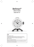
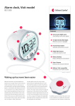
Bellman Alarm Clock
Be1341
Thank you for choosing products from Bellman & Symfon.
Bellman & Sym�on AB have both separate products and also complete
systems geared to helping people with impaired hearing. An example o�
this is the Bellman Visit 868 System, which consists o� a number o� radio
transmitters and receivers. The transmitters detect di��erent events in the
surrounding area and transmit a radio signal to the receivers. The receivers
pick up this signal and provide indications using light, sound and/or
vibration.
Read through the entire user manual �irst and then start to use the
products.
Technical information
Power supply
Mains power: 7.5 V DC / 1500 mA with
power supply unit BE9216 (Europe) and
BE9217 (United Kingdom).
Battery power: Internal NiMh type backup battery. The internal back-up battery
must be changed at a service workshop.
Charging: Via the power supply unit.
The discharged back-up battery will take
at least 24 hours to charge.
Activation
Getting started
Unpacking, installing and testing the unit
1.
Connect the power supply unit to the socket (12). The Bellman
Alarm Clock must be connected to mains power �or at least 24 hours
in order to operate correctly. Set the correct time with the Time
Setting Knob (11).
2.
Switch on the alarm with the Alarm Dial (5) by turning it to position
1. Turn the alarm pointer anticlockwise using the Alarm Call Knob
(10) until the alarm on the clock is activated. The Bellman Alarm
Clock will then emit sound and light signals and, i� a BE1270
Bellman Bed-shaker (accessory) is connected, it will vibrate. Press the
Snooze Button (4). The background light on the clock �ace will come
on at the same time as the alarm is switched o��. The snooze �unction
delays the alarm call �or approximately 3.5 minutes. The Alarm Dial
(5) is switched to position 0 to switch o�� the alarm completely.
3.
Place the Bellman Alarm Clock upright on a level sur�ace. The
Alarm Clock is usually placed near the bed but it can also be placed
somewhere else where it can easily be seen and heard. You can also
easily take your Alarm Clock with you wherever you go.
Alarm call: Built-in clock/alarm call
�unction
Analogue telephone network: 26 - 120
V RMS, 15 - 100 Hz.
External trigger: 3.5 mm stereo (mono
provides a connection) jack plug.
Connection: between the inner and outer
pins o� the mono type 3.5 mm jack plug
or between the middle/inner and outer
pins o� the stereo type 3.5 mm jack plug,
see diagram.
DC: 2 to 30 V between the inner pin and
middle pin on the stereo type
3.5 mm jack plug, see diagram.
AC: 3 to 24 V RMS 5 -150 Hz between
the inner pin and middle pin on the
stereo type 3.5 mm jack plug, see
diagram.
Output signals
Built-in sound signal: 80 dBA maximum
at 1 metre with a main �requency range
o� 500 - 1000 Hz.
Built-in flash light signal: Approx. 10
Candela. Warning! Flashes can cause
epileptic attacks.
Vibrator power: 2.0 - 4.0 V DC
Additional information
For indoor use only
Storlek W x H x D: 110 x 130 x 92 mm
Weight: 460 g
Colour: White with red base and red
buttons/dials
Flex length: Power supply unit 1.8 m
U
Accessories
Bellman Bed Vibrator BE1270
Bellman External Trigger Cable BE9086
Bellman Telephone Flex BE9105
Adapter plug �or the appropriate country
Page 148
Be1341
Techn�cal
Solut�ons
Bellman Visit System
Information
Function
General
The BE 1341 Bellman Alarm Clock is an Alarm Clock �or indoor use, which attracts the attention o�
the user using sound and light signals and also vibration i� a BE1270 Bellman Bed-shaker (accessory) is
connected.
It is activated by the clock’s alarm, by connection to an external trigger input (13) or via direct connection
to a telephone socket (15).
Clock
The Bellman Alarm Clock will indicate an alarm call via sound, �lash and vibration �or up to 15 minutes
unless the alarm is turned o�� or onto snooze. The sound ranges across several �requencies and increases in
volume to attract attention better.
Setting the current time
Set the correct time with the Time Setting Knob (11).
Setting an alarm call
Turn the Alarm Pointer anticlockwise to the desired call time using the Alarm Call Knob (10).
Activate the alarm by turning the Alarm Dial (5) to position 1. I� the power supply unit is connected, the
LEDs in the Snooze Button (4) will light up.
Snooze �unction
The snooze button lights when the alarm is activated and blinks when the snooze �unction is activated. To
conserve the built-in back-up battery, the snooze button will not light or blink when the external power
supply is disconnected, e.g. during a power �ailure.
The snooze �unction on the alarm delays the alarm call �or approximately 3.5 minutes by pressing the
Snooze Button (4). During this time the LEDs in the Snooze Button (4) will blink.
Switching o�� the alarm call
The alarm is switched o�� completely by switching the Alarm Dial (5) to position 0.
Illumination o� the clock �ace
The clock ace’s background light will come on when the alarm clock sounds or the snooze button (4) is
pressed.
Telephone connection
The telephone is connected via the Telephone Input (15). Use the BE9105 Telephone Flex (accessory) and
an adapter plug (accessory).
During activation via the telephone connection (15), �urther activations can be ignored �or 45 seconds i�
the Snooze Button (4) is pressed.
External trigger
It is possible to connect the vibrator output on several o Bellman & Sym on AB’s products or other
equipment that produces a contact or voltage to an external trigger (13) �or activation. In this way the
Bellman Alarm Clock can be made to work as alarm equipment, e.g. �or an existing �ire alarm.
During activation via the External Trigger (13), �urther activations can be disregarded �or 45 seconds i� the
Snooze Button (4) is pressed.
Be1341
Techn�calVisit
Solut�
ons Information
Bellman
System
Indicators and Signals
Sound
The Bellman Alarm Clock sounds an alarm. The sound volume is 80 dBA maximum at 1 metre.
The main �requency range is 500 - 1000 Hz.
Ljudet kan stä ngas av med Ljudomkopplaren (7).
Flashing light
When the Bellman Alarm Clock is activated, 4 built-in �lashing lights (17) �lash with a
bright white light.
The �lashing light can be switched o�� via the Flash Switch (9).
Vibration
The Bellman Alarm Clock can power two BE1270 Bellman Bed-shakers (accessory) which
are placed under the pillow to wake the user up when the Bellman Alarm Clock is activated
The Bed-shaker is connected to the sockets (14).
Power supply
The LED (1) is constantly green when the power supply unit is connected correctly.
When the LED (1) blinks green, the internal back-up battery is charged, but the Alarm Clock has
no external power supply, either because o� a power �ailure or because the power supply unit is not
connected.
When the LED (1) blinks yellow, the back-up battery is nearly �lat and the Alarm Clock has no external
power supply, either because o� a power �ailure or because the power supply unit is not connected. The
battery must be charged by connecting the power supply unit and allowing the Alarm Clock to charge
�or at least 24 hours.
Troubleshooting in brief
Symptom
Solution
Nothing happens.
•
Check that the power supply unit is connected
correctly and that the LED (1) is constantly green.
The LED (1) blinks.
•
Check that the power supply unit is connected
correctly.
The LEDs in the Snooze Button (4) do not come on
when the alarm clock is switched on.
•
Check that the power supply unit is connected
correctly.
The Alarm Clock does not emit any sound signals.
•
Check that the Sound Switch (7) is in the ON
position.
The Alarm Clock does not emit any lash signals.
•
Check that the Flash Switch (9) is in the ON
position.
Page 149
Page 150
Be1341
Techn�cal
Solut�ons
Bellman Visit System
Information
17
1.
2.
3.
4.
5.
6.
7.
8.
9.
10.
Power supply LED
Alarm pointer
Illuminated clock �ace
Illuminated snooze button
Alarm dial
Base
Sound switch
Signal switches �or external trigger
Flash switch
Alarm call knob
11.
12.
13.
14.
15.
16.
17.
Time setting knob
Input �or power supply unit
External trigger input.
Vibrator output
Analogue telephone input
Programming switch
Flashing lights
Be1341
Techn�calVisit
Solut�
ons Information
Bellman
System
Appendix - Further information
Further information
Adjustments
No adjustments apart �rom setting the time and selecting the call time are required �or normal use.
The relevant descriptions are provided below, i� you wish to change a setting �or some reason.
Signal pattern on external trigger
The signal type set during external activation and indicators and signals activated by an external
trigger can be altered using the switches (8), see �igure below.
DIP switch
settings
Up, Down, Not
Used
LED pattern
Sound
Vibration
Flash
Green is constantly
lit
1 x ding dong, low- Separate
�requency tone
Yes
Green blinks
constantly
2 x ding dong,
high-�requency
tone
Separate
Yes
Yellow is constantly 1 x ring, lowlit
�requency tone
Short
Yes
Yellow blinks
constantly
2 x ring ring, high�requency tone
Short
Yes
Orange blinks
constantly
Baby
Rapid
Yes
Orange blinks
constantly
Baby
Rapid
Yes
Red and Orange
constantly blink
alternately
VMA constant
Long
Yes
Red blinks
constantly
Fire alarm constant
Long
Yes
Page 151
Page 152
Be1341
Techn�cal
Solut�ons
Bellman Visit System
Information
Testing
It is easy to test the Bellman Alarm Clock, BE1341. I� the Alarm Clock does not work as described below, you
can check �urther under Troubleshooting guide.
How to test
The BE1341 Bellman Alarm Clock should always be connected to the electric socket with the enclosed power
supply unit.
To test the �lashing light, sound and vibration with the BE1270 Bellman Bed-shaker (accessory):
•
Switch on the alarm with the Alarm Dial (5) by turning it to position 1
•
Turn the Alarm Pointer anticlockwise using the Alarm Call Knob (10) until the alarm on the clock is
activated.
•
The Bellman Alarm Clock will give the ollowing indications:
o Switching on clock �ace background illumination (3).
o Flashing with the �lashing lights (17) on the �ront, provided that the Flash Switch (9) is in the ON
position.
o Emitting a sound signal, provided that the sound switch (7) is in the ON position.
o A BE1270 Bellman Bed-shaker (accessory) will vibrate i� connected
Two tests are required to carry out a �ull test o� the external trigger; one to test contact and another to test
voltage. For �urther in�ormation see Activation. Please note that when the Snooze Button (4) is pressed during
an alarm �rom an external trigger, any �urther alarm via the external trigger will be ignored �or 45 seconds.
•
•
•
Connect the alarm unit to the external trigger input (13).
Activate the alarm.
The Bellman Alarm Clock will give the ollowing indications:
o Flashing with the �lashing lights (17) on the �ront, provided that the Flash Switch (9) is in the ON
position.
o Emitting the sound signal selected via the external trigger signal switch (8), provided that the Sound
Switch (7) is in the ON position.
o I� the BE1270 Bellman Bed Shaker (accessory) is connected, it will vibrate in the way selected via the
external trigger signal switch (13).
To test the builtin telephone connection:
•
•
•
Connect input (15) on the Bellman Alarm Clock to an analogue telephone socket using a BE9105
telephone �lex (accessory) and an adapter plug (accessory).
Ring the telephone number
The Bellman Alarm Clock will give the ollowing indications:
o Flashing with the �lashing lights (17) on the �ront, provided that the Flash Switch (9) is in the ON
position.
o Emitting a ring-type sound signal, provided that the Sound Switch (7) is in the ON position.
o The BE1270 Bellman Bed Vibrator (accessory) will vibrate i� connected
Trouble shooting
You can carry out a number o� checks yoursel� be�ore sending a product �or repair.
Troubleshooting guide
Symptom
Solution
Nothing happens.
•
Check that the power supply unit is connected
correctly.
The LED (1) blinks.
•
Check that the power supply unit is connected
correctly.
The LEDs in the Snooze Button (4) do not come on
when the alarm clock is switched on.
•
Check that the power supply unit is connected
correctly.
The Alarm Clock does not emit any sound signals.
•
Check that the Sound Switch (7) is in the ON
position.
The Alarm Clock does not emit any lash signals.
•
Check that the Flash Switch (9) is in the ON
position.