1
Advanced CAE Applications for Professionals
Software that works — for you.SM
ASTROS
Programmer’s Manual
for Version 20
UNIVERSAL ANALYTICS, INC.
Publication AD-001
©1997 UNIVERSAL ANALYTICS, INC.
Torrance, California USA
All Rights Reserved
First Edition, March 1997
Second Edition, December 1997
Restricted Rights Legend:
The use, duplication, or disclosure of the information contained in this document is subject to the
restrictions set forth in your Software License Agreement with Universal Analytics, Inc. Use, duplication, or disclosure by the Government of the United States is subject to the restrictions set forth in
Subdivision (b)(3)(ii) of the Rights in Technical Data and Computer Software clause, 48 CFR
252.227-7013.
The information contained herein is subject to change without notice. Universal Analytics Inc. does
not warrant that this document is free of errors or defects and assumes no liability or responsibility to
any person or company for direct or indirect damages resulting from the use of any information
contained herein.
UNIVERSAL ANALYTICS, INC.
3625 Del Amo Blvd., Suite 370
Torrance, CA 90503
Tel: (310) 214-2922
FAX: (310) 214-3420
PROGRAMMER’S MANUAL
TABLE OF CONTENTS
1. INTRODUCTION . . . . . . . . . . . . . . . . . . . . . . . . . . . . 1-1
2. ASTROS SOFTWARE DESCRIPTION . . . . . . . . . . . . . . . . . 2-1
2.1. THE ASTROS SYSTEM . . . . . . . . . . . . . . . . . . . . . . . . . . . . . 2-2
2.1.1. SYSGEN Components . . . . . . . . . . . . . . . . . . . . . . . . . . . . . . . . . . . . 2-2
2.1.2. ASTROS Components . . . . . . . . . . . . . . . . . . . . . . . . . . . . . . . . . . . . 2-4
2.2. MAJOR FUNCTIONAL CODE BLOCKS . . . . . . . . . . . . . . . . . . . . . 2-4
2.3. CODE COMMON TO ASTROS AND SYSGEN . . . . . . . . . . . . . . . . . 2-7
3. SYSTEM INSTALLATION . . . . . . . . . . . . . . . . . . . . . . . 3-1
3.1. MACHINE DEPENDENT CODE . . . . . . . . . . . . . . . . . . . . . . . . . 3-2
3.1.1. General Dependent Code . . . . . . . . . . . . . . . . . . . . . . . . . . . . . . . . . . 3-3
3.1.2. Database Dependent Code . . . . . . . . . . . . . . . . . . . . . . . . . . . . . . . . . 3-22
3.2. THE SYSTEM GENERATION PROGRAM
3.2.1. Functional Module Definition . . . . .
3.2.2. Standard Solution Algorithm Definition
3.2.3. Bulk Data Template Definition . . . .
3.2.4. Relational Schema Definition . . . . .
3.2.5. Error Message Text Definition . . . .
.
.
.
.
.
.
.
.
.
.
.
.
.
.
.
.
.
.
.
.
. . . . . . . . . . . . . . . . . .
.
.
.
.
.
.
.
.
.
.
.
.
.
.
.
.
.
.
.
.
.
.
.
.
.
.
.
.
.
.
.
.
.
.
.
.
.
.
.
.
.
.
.
.
.
.
.
.
.
.
.
.
.
.
.
.
.
.
.
.
.
.
.
.
.
.
.
.
.
.
.
.
.
.
.
.
.
.
.
.
.
.
.
.
.
.
.
.
.
.
.
.
.
.
.
.
.
.
.
.
.
.
.
.
.
.
.
.
.
.
3.3. GENERATION OF THE ASTROS SYSTEM . . . . . . . . . . . . . . . . . .
3-46
.
.
.
.
.
3-47
3-51
3-51
3-55
3-56
3-58
4. EXECUTIVE SYSTEM . . . . . . . . . . . . . . . . . . . . . . . . . 4-1
ASTROS
i
PROGRAMMER’S MANUAL
5. ENGINEERING APPLICATION MODULES . . . . . . . . . . . . . . . 5-1
6. APPLICATION UTILITY MODULES . . . . . . . . . . . . . . . . . . . 6-1
7. LARGE MATRIX UTILITY MODULES . . . . . . . . . . . . . . . . . . 7-1
8. THE CADDB APPLICATION INTERFACE . . . . . . . . . . . . . . . 8-1
8.1. CADDB BASIC DESIGN CONCEPTS . . . . . . . . . . . . . . . . . . . . . . 8-4
8.1.1. Physical Structure . . . . . . . . . . . . . . . . . . . . . . . . . . . . . . . . . . . . . . . 8-5
8.1.2. Improvements Over Other Databases . . . . . . . . . . . . . . . . . . . . . . . . . . . . 8-5
8.1.3. Memory Requirements . . . . . . . . . . . . . . . . . . . . . . . . . . . . . . . . . . . . 8-6
8.2. THE GENERAL UTILITIES
. . . . . . . . . . . . . . . . . . . . . . . . . . . 8-7
8.3.THE USE OF eBASE . . . . . . . . . . . . . . . . . . . . . . . . . . . . . . . 8-8
8.4. THE DYNAMIC MEMORY MANAGER UTILITIES
. . . . . . . . . . . . . . . 8-20
8.5. UTILITIES FOR MATRIX ENTITIES . . . . . . . . . . . . . . . . . . . . . . . 8-32
8.5.1. Creating a Matrix. . . . . . . . . . . . . . . .
8.5.2. Packing and Unpacking a Matrix by Columns.
8.5.3. Obtaining Matrix Column Statistics. . . . . . .
8.5.4. Packing and Unpacking a Matrix by Terms. .
8.5.5. Packing and Unpacking a Matrix by Strings. .
8.5.6. Matrix Positioning. . . . . . . . . . . . . . .
8.5.7. Missing Matrix Columns. . . . . . . . . . . .
8.5.8. Repacking a Matrix. . . . . . . . . . . . . . .
.
.
.
.
.
.
.
.
.
.
.
.
.
.
.
.
.
.
.
.
.
.
.
.
.
.
.
.
.
.
.
.
.
.
.
.
.
.
.
.
.
.
.
.
.
.
.
.
.
.
.
.
.
.
.
.
.
.
.
.
.
.
.
.
.
.
.
.
.
.
.
.
.
.
.
.
.
.
.
.
.
.
.
.
.
.
.
.
.
.
.
.
.
.
.
.
.
.
.
.
.
.
.
.
.
.
.
.
.
.
.
.
.
.
.
.
.
.
.
.
.
.
.
.
.
.
.
.
.
.
.
.
.
.
.
.
.
.
.
.
.
.
.
.
.
.
.
.
.
.
.
.
.
.
.
.
.
.
.
.
.
.
.
.
.
.
.
.
.
.
.
.
.
.
.
.
.
.
.
.
.
.
.
.
8-32
8-33
8-33
8-34
8-35
8-36
8-37
8-38
8.6. UTILITIES FOR RELATIONAL ENTITIES . . . . . . . . . . . . . . . . . . . . 8-55
8.6.1. Examples of Relational Entity Utilities.
8.6.2. Creating a Relation. . . . . . . . . . .
8.6.3. Loading Relational Data. . . . . . . .
8.6.4. Accessing a Relation . . . . . . . . .
8.6.5. Updating a Relational entry. . . . . .
8.6.6. Other Operations. . . . . . . . . . . .
.
.
.
.
.
.
.
.
.
.
.
.
.
.
.
.
.
.
.
.
.
.
.
.
.
.
.
.
.
.
.
.
.
.
.
.
.
.
.
.
.
.
.
.
.
.
.
.
.
.
.
.
.
.
.
.
.
.
.
.
.
.
.
.
.
.
.
.
.
.
.
.
.
.
.
.
.
.
.
.
.
.
.
.
.
.
.
.
.
.
.
.
.
.
.
.
.
.
.
.
.
.
.
.
.
.
.
.
.
.
.
.
.
.
.
.
.
.
.
.
.
.
.
.
.
.
.
.
.
.
.
.
.
.
.
.
.
.
.
.
.
.
.
.
.
.
.
.
.
.
.
.
.
.
.
.
.
.
.
.
.
.
8-55
8-56
8-56
8-57
8-58
8-59
8.7. UTILITIES FOR UNSTRUCTURED ENTITIES . . . . . . . . . . . . . . . . . 8-81
8.7.1. Generating an Unstructured Entity . . . . . . . . . . . . . . . . . . . . . . . . . . . . . 8-81
8.7.2. Accessing an Unstructured Entity. . . . . . . . . . . . . . . . . . . . . . . . . . . . . . 8-82
8.7.3. Modifying an Unstructured Entity. . . . . . . . . . . . . . . . . . . . . . . . . . . . . . . 8-83
ii
ASTROS
PROGRAMMER’S MANUAL
ALPHABETICAL INDEX OF
SOFTWARE MODULES
ABOUND . . . . . . . . . . . . . . . . . . . . . . 5-3
BOUNDUPD . . . . . . . . . . . . . . . . . . . . 5-31
ACTCON . . . . . . . . . . . . . . . . . . . . . . . 5-5
CDCOMP . . . . . . . . . . . . . . . . . . . . . . 7-2
AEROEFFS . . . . . . . . . . . . . . . . . . . . . . 5-7
CEIG . . . . . . . . . . . . . . . . . . . . . . . . . 7-3
AEROSENS . . . . . . . . . . . . . . . . . . . . 5-10
COLMERGE . . . . . . . . . . . . . . . . . . . . . 7-5
AMP . . . . . . . . . . . . . . . . . . . . . . . . . 5-13
COLPART . . . . . . . . . . . . . . . . . . . . . . 7-6
ANALINIT . . . . . . . . . . . . . . . . . . . . . 5-16
CONORDER . . . . . . . . . . . . . . . . . . . . 5-32
APFLUSH . . . . . . . . . . . . . . . . . . . . . 5-17
DAXB . . . . . . . . . . . . . . . . . . . . . . . . . 6-3
APPEND . . . . . . . . . . . . . . . . . . . . . . . 6-2
DBCINI . . . . . . . . . . . . . . . . . . . . . . . 4-7
AROSNSDR . . . . . . . . . . . . . . . . . . . . 5-18
DBCLOS . . . . . . . . . . . . . . . . . . . . . . . 8-9
AROSNSMR . . . . . . . . . . . . . . . . . . . . 5-22
DBCREA . . . . . . . . . . . . . . . . . . . . . . . 8-10
ASTROS . . . . . . . . . . . . . . . . . . . . . . . 4-2
DBDEST . . . . . . . . . . . . . . . . . . . . . . . 8-11
BCBGPDT . . . . . . . . . . . . . . . . . . . . . 5-24
DBEQUV . . . . . . . . . . . . . . . . . . . . . . . 8-12
BCBULK . . . . . . . . . . . . . . . . . . . . . . 5-25
DBEXIS . . . . . . . . . . . . . . . . . . . . . . . . 8-13
BCEVAL . . . . . . . . . . . . . . . . . . . . . . 5-26
DBFLSH . . . . . . . . . . . . . . . . . . . . . . . 8-14
BCIDVAL . . . . . . . . . . . . . . . . . . . . . 5-28
DBINIT . . . . . . . . . . . . . . . . . . . . . . . 4-7
BCIDVL . . . . . . . . . . . . . . . . . . . . . . 5-28
DBMDAB . . . . . . . . . . . . . . . . . . . . . . 3-23
BKLEVA . . . . . . . . . . . . . . . . . . . . . . 5-157
DBMDAN . . . . . . . . . . . . . . . . . . . . . . 3-24
BKSENS . . . . . . . . . . . . . . . . . . . . . . 5-158
DBMDC1 . . . . . . . . . . . . . . . . . . . . . . 3-26
BOUND . . . . . . . . . . . . . . . . . . . . . . 5-29
DBMDC2 . . . . . . . . . . . . . . . . . . . . . . 3-26
ASTROS
vii
PROGRAMMER’S MANUAL
DBMDCH . . . . . . . . . . . . . . . . . . . . . . 3-25
DYNRSP . . . . . . . . . . . . . . . . . . . . . . 5-44
DBMDDT . . . . . . . . . . . . . . . . . . . . . . 3-28
EBKLEVAL . . . . . . . . . . . . . . . . . . . . . 5-46
DBMDER . . . . . . . . . . . . . . . . . . . . . . 3-29
EBKLSENS . . . . . . . . . . . . . . . . . . . . . 5-47
DBMDFP . . . . . . . . . . . . . . . . . . . . . . 3-30
EDR . . . . . . . . . . . . . . . . . . . . . . . . . 5-48
DBMDHC . . . . . . . . . . . . . . . . . . . . . . 3-31
EMA1 . . . . . . . . . . . . . . . . . . . . . . . . 5-51
DBMDHX . . . . . . . . . . . . . . . . . . . . . . 3-32
EMA2 . . . . . . . . . . . . . . . . . . . . . . . . 5-53
DBMDI1 . . . . . . . . . . . . . . . . . . . . . . 3-33
EMG . . . . . . . . . . . . . . . . . . . . . . . . . 5-55
DBMDI2 . . . . . . . . . . . . . . . . . . . . . . 3-34
FBS . . . . . . . . . . . . . . . . . . . . . . . . . . . 7-8
DBMDLC . . . . . . . . . . . . . . . . . . . . . . 3-35
FCEVAL . . . . . . . . . . . . . . . . . . . . . . . 5-58
DBMDLF . . . . . . . . . . . . . . . . . . . . . . 3-36
FLUTDMA . . . . . . . . . . . . . . . . . . . . . 5-59
DBMDMM . . . . . . . . . . . . . . . . . . . . . 3-37
FLUTDRV . . . . . . . . . . . . . . . . . . . . . 5-61
DBMDOF . . . . . . . . . . . . . . . . . . . . . . 3-38
FLUTQHHL . . . . . . . . . . . . . . . . . . . . 5-62
DBMDOR . . . . . . . . . . . . . . . . . . . . . . 3-39
FLUTSENS . . . . . . . . . . . . . . . . . . . . . 5-65
DBMDRD . . . . . . . . . . . . . . . . . . . . . . 3-40
FLUTTRAN . . . . . . . . . . . . . . . . . . . . 5-68
DBMDSI . . . . . . . . . . . . . . . . . . . . . . 3-42
FNEVAL . . . . . . . . . . . . . . . . . . . . . . 5-70
DBMDTR . . . . . . . . . . . . . . . . . . . . . . 3-43
FPKEVL . . . . . . . . . . . . . . . . . . . . . . . 5-71
DBMDWR . . . . . . . . . . . . . . . . . . . . . 3-44
FREDUCE . . . . . . . . . . . . . . . . . . . . . . 5-72
DBMDZB . . . . . . . . . . . . . . . . . . . . . . 3-45
FREQSENS . . . . . . . . . . . . . . . . . . . . . 5-75
DBNEMP . . . . . . . . . . . . . . . . . . . . . . 8-15
FSD . . . . . . . . . . . . . . . . . . . . . . . . . 5-77
DBOPEN . . . . . . . . . . . . . . . . . . . . . . 8-16
GDR1 . . . . . . . . . . . . . . . . . . . . . . . . 5-79
DBRENA . . . . . . . . . . . . . . . . . . . . . . 8-18
GDR2 . . . . . . . . . . . . . . . . . . . . . . . . 5-81
DBSWCH . . . . . . . . . . . . . . . . . . . . . . 8-19
GDR3 . . . . . . . . . . . . . . . . . . . . . . . . 5-82
DBTERM . . . . . . . . . . . . . . . . . . . . . . 4-12
GDR4 . . . . . . . . . . . . . . . . . . . . . . . . 5-84
DCEVAL . . . . . . . . . . . . . . . . . . . . . . 5-33
GDVGRAD . . . . . . . . . . . . . . . . . . . . 5-86
DDLOAD . . . . . . . . . . . . . . . . . . . . . . 5-34
GDVPRINT . . . . . . . . . . . . . . . . . . . . 5-87
DECOMP . . . . . . . . . . . . . . . . . . . . . . . 7-7
GDVPUNCH . . . . . . . . . . . . . . . . . . . . 5-88
DESIGN . . . . . . . . . . . . . . . . . . . . . . . 5-36
GDVRESP . . . . . . . . . . . . . . . . . . . . . 5-89
DESPUNCH . . . . . . . . . . . . . . . . . . . . 5-38
GENELPRT . . . . . . . . . . . . . . . . . . . . . 5-90
DMA . . . . . . . . . . . . . . . . . . . . . . . . . 5-39
GFBS . . . . . . . . . . . . . . . . . . . . . . . . . 7-9
DOUBLE . . . . . . . . . . . . . . . . . . . . . . . 3-4
GMMATC . . . . . . . . . . . . . . . . . . . . . . 6-4
DVMOVLIM . . . . . . . . . . . . . . . . . . . . 5-41
GMMATD . . . . . . . . . . . . . . . . . . . . . . 6-5
DYNLOAD . . . . . . . . . . . . . . . . . . . . . 5-42
GMMATS . . . . . . . . . . . . . . . . . . . . . . 6-6
viii
ASTROS
PROGRAMMER’S MANUAL
GPSP . . . . . . . . . . . . . . . . . . . . . . . . 5-91
MMGETB . . . . . . . . . . . . . . . . . . . . . . 8-28
GPWG . . . . . . . . . . . . . . . . . . . . . . . 5-92
MMINIT . . . . . . . . . . . . . . . . . . . . . . . 4-6
GREDUCE . . . . . . . . . . . . . . . . . . . . . 5-93
MMREDU . . . . . . . . . . . . . . . . . . . . . . 8-29
GTLOAD . . . . . . . . . . . . . . . . . . . . . . 5-95
MMSQUZ . . . . . . . . . . . . . . . . . . . . . . 8-30
IFP . . . . . . . . . . . . . . . . . . . . . . . . . . 5-97
MMSTAT . . . . . . . . . . . . . . . . . . . . . . 8-31
INERTIA . . . . . . . . . . . . . . . . . . . . . . 5-99
MPYAD . . . . . . . . . . . . . . . . . . . . . . . 7-11
INVERC . . . . . . . . . . . . . . . . . . . . . . . 6-7
MSGDMP . . . . . . . . . . . . . . . . . . . . . . 6-10
INVERD . . . . . . . . . . . . . . . . . . . . . . . 6-8
MSWGGRAD . . . . . . . . . . . . . . . . . . . 5-125
INVERS . . . . . . . . . . . . . . . . . . . . . . . 6-9
MSWGRESP . . . . . . . . . . . . . . . . . . . . 5-126
ITERINIT . . . . . . . . . . . . . . . . . . . . . 5-100
MXADD . . . . . . . . . . . . . . . . . . . . . . . 7-13
LAMINCON . . . . . . . . . . . . . . . . . . . . 5-101
MXFORM . . . . . . . . . . . . . . . . . . . . . . 8-39
LAMINSNS . . . . . . . . . . . . . . . . . . . . 5-102
MXFRMSYM . . . . . . . . . . . . . . . . . . . 5-127
LDVLOAD . . . . . . . . . . . . . . . . . . . . . 5-104
MXINIT . . . . . . . . . . . . . . . . . . . . . . . 8-40
LDVPRINT . . . . . . . . . . . . . . . . . . . . 5-105
MXNPOS . . . . . . . . . . . . . . . . . . . . . . 8-41
LODGEN . . . . . . . . . . . . . . . . . . . . . . 5-106
MXPAK . . . . . . . . . . . . . . . . . . . . . . . 8-42
MAKDFU . . . . . . . . . . . . . . . . . . . . . 5-108
MXPKT . . . . . . . . . . . . . . . . . . . . . . . . 8-43
MAKDFV . . . . . . . . . . . . . . . . . . . . . 5-110
MXPKTF . . . . . . . . . . . . . . . . . . . . . . . 8-44
MAKDVU . . . . . . . . . . . . . . . . . . . . . 5-112
MXPKTI . . . . . . . . . . . . . . . . . . . . . . . 8-45
MAKEST . . . . . . . . . . . . . . . . . . . . . . 5-113
MXPKTM . . . . . . . . . . . . . . . . . . . . . . 8-46
MAPOL . . . . . . . . . . . . . . . . . . . . . . . . 4-9
MXPOS . . . . . . . . . . . . . . . . . . . . . . . . 8-47
MERGE . . . . . . . . . . . . . . . . . . . . . . . 7-10
MXRPOS . . . . . . . . . . . . . . . . . . . . . . . 8-48
MK2GG . . . . . . . . . . . . . . . . . . . . . . 5-116
MXSTAT . . . . . . . . . . . . . . . . . . . . . . . 8-49
MKAMAT . . . . . . . . . . . . . . . . . . . . . 5-117
MXUNP . . . . . . . . . . . . . . . . . . . . . . . 8-50
MKDFDV . . . . . . . . . . . . . . . . . . . . . 5-119
MXUPT . . . . . . . . . . . . . . . . . . . . . . . . 8-51
MKDFSV . . . . . . . . . . . . . . . . . . . . . . 5-120
MXUPTF . . . . . . . . . . . . . . . . . . . . . . . 8-52
MKPVECT . . . . . . . . . . . . . . . . . . . . . 5-122
MXUPTI . . . . . . . . . . . . . . . . . . . . . . . 8-53
MKUSET . . . . . . . . . . . . . . . . . . . . . . 5-123
MXUPTM . . . . . . . . . . . . . . . . . . . . . . 8-54
MMBASC . . . . . . . . . . . . . . . . . . . . . 8-23
NLEMA1 . . . . . . . . . . . . . . . . . . . . . . 5-128
MMBASE . . . . . . . . . . . . . . . . . . . . . 8-24
NLEMG . . . . . . . . . . . . . . . . . . . . . . 5-131
MMDUMP . . . . . . . . . . . . . . . . . . . . . 8-25
NLLODGEN . . . . . . . . . . . . . . . . . . . . 5-133
MMFREE . . . . . . . . . . . . . . . . . . . . . . 8-26
NREDUCE . . . . . . . . . . . . . . . . . . . . . 5-135
MMFREG . . . . . . . . . . . . . . . . . . . . . 8-27
NULLMAT . . . . . . . . . . . . . . . . . . . . 5-137
ASTROS
ix
PROGRAMMER’S MANUAL
OFPAEROM . . . . . . . . . . . . . . . . . . . 5-138
RECOVA . . . . . . . . . . . . . . . . . . . . . . 5-165
OFPALOAD . . . . . . . . . . . . . . . . . . . 5-140
RECPOS . . . . . . . . . . . . . . . . . . . . . . . 8-66
OFPDISP . . . . . . . . . . . . . . . . . . . . . 5-143
REENDC . . . . . . . . . . . . . . . . . . . . . . 8-67
OFPDLOAD . . . . . . . . . . . . . . . . . . . 5-146
REGB . . . . . . . . . . . . . . . . . . . . . . . . 8-68
OFPEDR . . . . . . . . . . . . . . . . . . . . . . 5-148
REGBM . . . . . . . . . . . . . . . . . . . . . . . 8-69
OFPGRAD . . . . . . . . . . . . . . . . . . . . 5-150
REGET . . . . . . . . . . . . . . . . . . . . . . . 8-70
OFPLOAD . . . . . . . . . . . . . . . . . . . . 5-151
REGETM . . . . . . . . . . . . . . . . . . . . . . 8-71
OFPMROOT . . . . . . . . . . . . . . . . . . . 5-153
REIG . . . . . . . . . . . . . . . . . . . . . . . . . 7-15
OFPSPCF . . . . . . . . . . . . . . . . . . . . . 5-154
RENULx . . . . . . . . . . . . . . . . . . . . . . . 8-72
PARTN . . . . . . . . . . . . . . . . . . . . . . . 7-14
REPOS . . . . . . . . . . . . . . . . . . . . . . . 8-73
PBKLEVAL . . . . . . . . . . . . . . . . . . . . 5-157
REPROJ . . . . . . . . . . . . . . . . . . . . . . . 8-74
PBKLSENS . . . . . . . . . . . . . . . . . . . . 5-158
REQURY . . . . . . . . . . . . . . . . . . . . . . 8-75
PFBULK . . . . . . . . . . . . . . . . . . . . . . 5-159
RESCHM . . . . . . . . . . . . . . . . . . . . . . 8-76
POLCOD . . . . . . . . . . . . . . . . . . . . . . 6-11
RESETC . . . . . . . . . . . . . . . . . . . . . . . 8-77
POLCOS . . . . . . . . . . . . . . . . . . . . . . . 6-12
RESORT . . . . . . . . . . . . . . . . . . . . . . 8-78
POLEVD . . . . . . . . . . . . . . . . . . . . . . 6-13
REUPD . . . . . . . . . . . . . . . . . . . . . . . 8-79
POLEVS . . . . . . . . . . . . . . . . . . . . . . . 6-14
REUPDM . . . . . . . . . . . . . . . . . . . . . . 8-80
POLSLD . . . . . . . . . . . . . . . . . . . . . . . 6-15
ROWMERGE . . . . . . . . . . . . . . . . . . . . 7-16
POLSLS . . . . . . . . . . . . . . . . . . . . . . . 6-16
ROWPART . . . . . . . . . . . . . . . . . . . . . 7-17
PREPAS . . . . . . . . . . . . . . . . . . . . . . . . 4-4
SAERO . . . . . . . . . . . . . . . . . . . . . . . 5-167
PS . . . . . . . . . . . . . . . . . . . . . . . . . . . 6-17
SAERODRV . . . . . . . . . . . . . . . . . . . . 5-171
PVCDRV . . . . . . . . . . . . . . . . . . . . . 5-122
SAEROMRG . . . . . . . . . . . . . . . . . . . . 5-173
QHHLGEN . . . . . . . . . . . . . . . . . . . . 5-161
SAXB . . . . . . . . . . . . . . . . . . . . . . . . 6-20
RBCHECK . . . . . . . . . . . . . . . . . . . . 5-163
SCEVAL . . . . . . . . . . . . . . . . . . . . . . . 5-175
RDDMAT . . . . . . . . . . . . . . . . . . . . . . 6-18
SDCOMP . . . . . . . . . . . . . . . . . . . . . . 7-18
RDSMAT . . . . . . . . . . . . . . . . . . . . . . 6-19
SHAPEGEN . . . . . . . . . . . . . . . . . . . . 6-21
REAB . . . . . . . . . . . . . . . . . . . . . . . . 8-60
SOLUTION . . . . . . . . . . . . . . . . . . . . . 5-178
REABM . . . . . . . . . . . . . . . . . . . . . . . 8-61
SPLINES . . . . . . . . . . . . . . . . . . . . . . 5-180
READD . . . . . . . . . . . . . . . . . . . . . . . 8-62
SPLINEU . . . . . . . . . . . . . . . . . . . . . . 5-182
READDM . . . . . . . . . . . . . . . . . . . . . . 8-63
STEADY . . . . . . . . . . . . . . . . . . . . . . 5-184
RECLRC . . . . . . . . . . . . . . . . . . . . . . . 8-64
TCEVAL . . . . . . . . . . . . . . . . . . . . . . 5-186
RECOND . . . . . . . . . . . . . . . . . . . . . . 8-65
TRIMCHEK . . . . . . . . . . . . . . . . . . . . 5-188
x
ASTROS
PROGRAMMER’S MANUAL
TRNSPOSE . . . . . . . . . . . . . . . . . . . . 7-19
UTSTOD, UTDTOS . . . . . . . . . . . . . . . . 6-43
UNGET . . . . . . . . . . . . . . . . . . . . . . . 8-84
UTUPRT . . . . . . . . . . . . . . . . . . . . . . . 6-44
UNGETP . . . . . . . . . . . . . . . . . . . . . . 8-85
UTZERD . . . . . . . . . . . . . . . . . . . . . . . 6-45
UNPOS . . . . . . . . . . . . . . . . . . . . . . . 8-86
UTZERS . . . . . . . . . . . . . . . . . . . . . . . 6-46
UNPUT . . . . . . . . . . . . . . . . . . . . . . . 8-87
WOBJGD . . . . . . . . . . . . . . . . . . . . . 5-192
UNPUTP . . . . . . . . . . . . . . . . . . . . . . 8-88
WOBJGRAD . . . . . . . . . . . . . . . . . . . 5-192
UNRPOS . . . . . . . . . . . . . . . . . . . . . . 8-89
XISTOI . . . . . . . . . . . . . . . . . . . . . . . . 6-47
UNSTAT . . . . . . . . . . . . . . . . . . . . . . 8-90
XISTOR . . . . . . . . . . . . . . . . . . . . . . . 6-48
UNSTEADY . . . . . . . . . . . . . . . . . . . . 5-190
XQENDS . . . . . . . . . . . . . . . . . . . . . . . 4-11
USETPRT . . . . . . . . . . . . . . . . . . . . . 6-22
XQINIT . . . . . . . . . . . . . . . . . . . . . . . 4-3
UTCOPY . . . . . . . . . . . . . . . . . . . . . . 6-23
XQTMON . . . . . . . . . . . . . . . . . . . . . . 4-10
UTCSRT . . . . . . . . . . . . . . . . . . . . . . 6-24
XXBCLR . . . . . . . . . . . . . . . . . . . . . . . 3-5
UTEXIT . . . . . . . . . . . . . . . . . . . . . . . 6-25
XXBD . . . . . . . . . . . . . . . . . . . . . . . . . 3-6
UTGPRT . . . . . . . . . . . . . . . . . . . . . . 6-26
XXBSET . . . . . . . . . . . . . . . . . . . . . . . 3-7
UTMCOR . . . . . . . . . . . . . . . . . . . . . 6-27
XXBTST . . . . . . . . . . . . . . . . . . . . . . . 3-8
UTMINT . . . . . . . . . . . . . . . . . . . . . . 6-28
XXCLOK . . . . . . . . . . . . . . . . . . . . . . . 3-9
UTMPRG,UTRPRG,UTUPRG . . . . . . . . . 6-29
XXCPU . . . . . . . . . . . . . . . . . . . . . . . . 3-10
UTMPRT . . . . . . . . . . . . . . . . . . . . . . 6-30
XXDATE . . . . . . . . . . . . . . . . . . . . . . . 3-11
UTMWRT . . . . . . . . . . . . . . . . . . . . . 6-31
XXFLSH . . . . . . . . . . . . . . . . . . . . . . . 3-12
UTPAGE, UTPAG2 . . . . . . . . . . . . . . . . 6-33
XXINIT . . . . . . . . . . . . . . . . . . . . . . . . 3-13
UTRPRT . . . . . . . . . . . . . . . . . . . . . . 6-34
XXITOS . . . . . . . . . . . . . . . . . . . . . . . 3-14
UTRSRT . . . . . . . . . . . . . . . . . . . . . . 6-35
XXLSFT . . . . . . . . . . . . . . . . . . . . . . . . 3-15
UTSFLG, UTSFLR, UTGFLG, UTGFLR . . . . 6-36
XXNOT . . . . . . . . . . . . . . . . . . . . . . . . 3-16
UTSORT . . . . . . . . . . . . . . . . . . . . . . 6-37
XXOVFL . . . . . . . . . . . . . . . . . . . . . . . 3-17
UTSRCH . . . . . . . . . . . . . . . . . . . . . . 6-38
XXRAND . . . . . . . . . . . . . . . . . . . . . . . 3-18
UTSRT3 . . . . . . . . . . . . . . . . . . . . . . 6-39
XXRSFT . . . . . . . . . . . . . . . . . . . . . . . 3-19
UTSRTD . . . . . . . . . . . . . . . . . . . . . . 6-40
XXRTOS . . . . . . . . . . . . . . . . . . . . . . . 3-20
UTSRTI . . . . . . . . . . . . . . . . . . . . . . . 6-41
XXULNS . . . . . . . . . . . . . . . . . . . . . . . 3-21
UTSRTR . . . . . . . . . . . . . . . . . . . . . . 6-42
YSMERGE . . . . . . . . . . . . . . . . . . . . . 5-193
ASTROS
xi
PROGRAMMER’S MANUAL
This page is intentionally blank.
xii
ASTROS
PROGRAMMER’S MANUAL
Chapter 1.
INTRODUCTION
There are five manuals documenting ASTROS, the Automated Structural Optimization System:
• The User’s Reference Manual
• The Theoretical Manual
• The Programmer’s Manual
• The ASTROS eBASE Schemata Description
• The Installation and System Support Manual
This Programmer’s Manual gives the detailed description of ASTROS software. It describes the system in
terms of its software components, documents the procedure for installing ASTROS on different host
machines and provides detailed documentation of the application and utility modules that comprise the
procedure. In addition, the data structures of the database entities are presented in detail. This manual
is intended to provide the system administrator with a guide to the existing software and the researcher
with sufficient information to add application modules or otherwise manipulate the data generated by
the ASTROS system. Using standard ASTROS features does not require a familiarity with the information contained in this manual except, perhaps, for the entity documentation, which is useful when
additional database entities are to be viewed.
This document, while useful to the advanced engineering user, is directed toward the system administrator or code developer. This is the individual referred to by the term user unless otherwise indicated. The
Programmer’s Manual is structured in this way because all the information needed by the engineering
user is contained as a subset of that needed by the system administrator. As a consequence, however, the
manual is not as simple for the analyst as might be desired. It is anticipated that the advanced application user will need to sift through the module documentation and entity documentation to extract the
information needed to modify the ASTROS execution path or to insert additional modules for performing
ASTROS
INTRODUCTION 1-1
PROGRAMMER’S MANUAL
alternative computations, printing additional results, writing data in alternative formats or other advanced features that may be performed.
As an introduction to the ASTROS system, Chapter 2 contains a description of the software structure of
ASTROS, both to provide a resource for the system administrator and to be a road map for the application user in identifying specific modules relevant to the task of interest. Chapter 2 attempts to introduce
the user to the totality of ASTROS source code and their interrelationships so that subsequent reading
will be more readily interpretable: in essence, Chapter 2 provides a nomenclature section enabling the
reader to identify (with the inevitable exceptions) the major unit (module) or functional library to which a
particular program belongs. This shapter provides a framework for subsequent shapters in the Programmer’s Manual.
Chapter 3 is devoted to the installation of the ASTROS system on various host computers. The steps
involved in installing the system are given, followed by detailed documentation of all the machine and
installation dependent code. Sufficient detail is given to allow someone familiar with the target host
system to write a set of machine-dependent code for that machine or site. This documentation is followed
by the description of the System Generation Process (SYSGEN) and its inputs. These inputs, along with
the SYSGEN program, define the system database which, in turn, defines system data to the ASTROS
executive. It is these inputs which the researcher may wish to modify to define a new module, define a
new set of inputs or make other advanced modifications of the system. A brief presentation of the order of
the operations that follow preparation of the machine dependent library is given to complete an installation of the system.
Chapters 4 through 8 contain the formal documentation of the ASTROS modules. Chapter 4 documents
those portions of the code that are considered to be at the system level. This means that the user need not
be aware of their existence but they are important in the overall system architecture. Further, they
perform many tasks of which the user may want to be aware if any system modifications are to be made.
Chapters 6 through 8 document the utilities that are associated with the ASTROS application modules,
matrix operations and the database. These shapters are the most important from the view of the advanced researcher/user in that these are the software tools from which additional capabilities can be put
together with reasonable rapidity. In each case, the executive (MAPOL) and application interface is fully
defined and the algorithm of the utility is outlined.
Chapter 9 contains the documentation of the data structures on the CADDB database that are used by
the ASTROS system. The contents and structure of each database entity are given along with an
indication of the module that generates the data and which modules use the data. For matrix entities,
the relevant shapter of the Theoretical Manual is also referenced since the entity contents are more
clearly understood in the content of the equations that are highlighted there.
Chapter 10 contains a presentation of notes for the ASTROS application programmer. It is felt that the
ASTROS system has been designed with sufficient flexibility that the additional features or minor
enhancements are desired. Chapter 10, therefore, attempts to address some issues involved in writing an
ASTROS module. Rules and guidelines are given which will help the programmer avoid complications
arising from the interface of the new module and application utilities are also given. Particular emphasis
is placed on the memory management utilities and the database utilities since these require a more
sophisticated interface than the simple application utilities.
1-2 INTRODUCTION
ASTROS
PROGRAMMER’S MANUAL
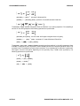
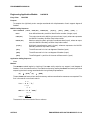
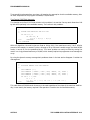
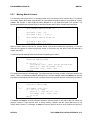
< module type> Module:
Entry Point:
<name>
<FORTRAN calling list for module>
PURPOSE:
<one or two sentence description>
MAPOL Calling Sequence:
<Executive system access method>
Application Calling Sequence:
<FORTRAN call followed by input description>
Method:
<Description of the module’s action>
Design Requirements:
<Indicates what the module expects to have completed in the context of the standard
sequence>
Error Conditions:
<Brief description of major error conditions that are trapped by the module>
Figure 1-1. Module Documentation Format
A standard documentation format has been adopted for the modules that are described in Chapter 3
through 8. Figure 1 illustrates this format and provides a key for identifying the data that are given for
each module. While this format is brief, enough information is given for the user to identify the principal
action of the module and the role it plays in the standard ASTROS execution. The utility modules are
documented to the extent necessary for an application programmer to use the utility in any new code to
be inserted in the system.
ASTROS
INTRODUCTION 1-3
PROGRAMMER’S MANUAL
This page is intentionally blank.
1-4 INTRODUCTION
ASTROS
PROGRAMMER’S MANUAL
Chapter 2.
ASTROS SOFTWARE DESCRIPTION
ASTROS is a software system made up of two separate executable programs comprising over 1500
independently addressable code segments containing approximately 300,000 lines of FORTRAN. While
this Programmer’s manual is devoted primarily to the detailed documentation to the separate modules
and subroutines of the ASTROS system, an overview of that system is necessary to understand how the
individual pieces fit together. This section introduces the ASTROS system and describes the software
structure of ASTROS in terms of its major code blocks. Both the system generation program, SYSGEN,
and the main program, ASTROS, are described and their interrelationships are illustrated. This section
provides a resource for the system administrator and a road map for the application programmer to
identify the section documenting modules relevant to the task of interest. This section also provides a
framework to direct the subsequent sections in the Programmer’s Manual.
In the context of the Programmer’s Manual, the structure of the ASTROS system refers to the interrelationships among the major code blocks. Typically, an analysis of the software associated with an individual code segment will indicate the nature of the task being performed and provide information on the
mechanisms by which intramodular communication takes place. The larger picture, in which the intermodular requirements of a particular code segment becomes clear, is more difficult to grasp. It is that
picture which this section attempts to provide.
The magnitude of the ASTROS system requires that the code segments be grouped into abstract collections of code such as utility modules and the database in order to be understood. While necessary, these
abstract collections can also obscure the picture of the system since a great deal of the detail is necessarily lost. Nonetheless, since a discussion of each individual code segment is not possible, a set of code
blocks has been defined for the purpose of writing the Programmer’s Manual. Naturally, there are many
ways in which the code segments could be grouped to aid the user in understanding the code segments
and their interactions. For the Programmer’s Manual, the code is grouped in a hierarchical manner by
function: that is, code segments that perform similar tasks at a similar level (relative to the executive
ASTROS
ASTROS SOFTWARE DESCRIPTION 2-1
PROGRAMMER’S MANUAL
system) are grouped together. Some segments of the code, of course, do not fit clearly into this sort of
functional abstraction. Their role is such that they could lie in more than one group or really don’t belong
to any group that has been defined. These exceptions complicate the issue but do not destroy the utility of
the functional breakdown of the code. When a module could be documented with more than one code
group, this fact is noted in the appropriate manual sections.
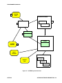
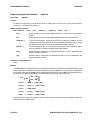
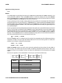
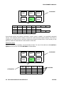
2.1. THE ASTROS SYSTEM
The highest level of abstraction is illustrated in Figure 2, which presents the two executable images that
comprise the ASTROS system, their inputs, outputs, and interrelationships. Referring to the figure, each
of the illustrated components is briefly described in the following sections.
2.1.1. SYSGEN Components
The SYSGEN program is a stand-alone executable program that is used to define ASTROS system
parameters. The use of an executable program that is directed by a set of inputs was adopted to provide a
simple mechanism to expand the capabilities of the ASTROS procedure. The inputs, outputs, and use of
this very important feature of the ASTROS architecture are fully documented in Section 3.2. The SYSGEN program consists of five items indicated by the numbered boxes in Figure 2. Each of these is briefly
discussed below:
1. The SYSGEN INPUTS consist of a set of files that define certain system level data that is written
by SYSGEN to the system database, SYSDB.
2. SYSGEN is an executable program that reads the SYSGEN INPUTS and creates a set of
database entities on SYSDB that provide data to the ASTROS executive and high level
engineering modules.
3. The SYSTEM DATABASE, SYSDB, consists of an index file, SYSDBIX, and (typically) a single
data file, SYSDB01. The SYSGEN program creates and loads database entities onto the system
database which defines:
a. The set of modules which can be addressed through the MAPOL language
b. The set of relational schemata for all relations declared in the MAPOL sequence
c.
The set of input Bulk Data entries
d. The error message texts for most run time error messages
e.
The standard MAPOL sequence to direct the execution of the ASTROS
4. XQDRIV is a FORTRAN subroutine written by SYSGEN that must be compiled and linked into
the ASTROS executable during the generation of the ASTROS executable image. It is the
XQDRIV subroutine that forms the FORTRAN link between the MAPOL language and the
application/utility modules.
5. The SYSGEN OUTPUT FILE is a listing generated by SYSGEN that echoes all the data stored
on the system database. As such, it provides a resource for the application user and the system
administrator documenting the current ASTROS system. Since this file represents what is, by
2-2 ASTROS SOFTWARE DESCRIPTION
ASTROS
PROGRAMMER’S MANUAL
1
SYSGEN
INPUT
SYSTEM DATABASE
SYSGEN
SYSDBIX
2
3
SYSDB01
XQDRV
4
ASTROS
XQDRV
SYSGEN
OUTPUT
5
INPUT
STREAM
RUN-TIME DATABASE
OUTPUT
FILE
RUNDBIX
RUNDB01
RUNDB02
Figure 2-1. ASTROS System Overview
ASTROS
ASTROS SOFTWARE DESCRIPTION 2-3
PROGRAMMER’S MANUAL
definition, the ASTROS program, any problems that arise or questions in the documentation
should be checked against the data in this file. If any discrepancies exist, either the documentation is in error or the SYSGEN inputs are in error. In any case, the ASTROS program is
directed by the SYSGEN data.
2.1.2. ASTROS Components
As illustrated in Figure 2, the XQDRIV subroutine and SYSDB are also part of the ASTROS program. The
XQDRIV subroutine is needed to generate the executable image and the SYSDB files MUST be available
on a read-only basis by the ASTROS program whenever an ASTROS job is run. The ASTROS program is
comprised of the following:
1. XQDRIV is a FORTRAN subroutine written by SYSGEN that must be compiled and linked into
the ASTROS executable during the generation of the ASTROS executable image. It is the
XQDRIV subroutine that forms the FORTRAN link between the MAPOL language and the
application/utility modules.
2. The SYSTEM DATABASE, SYSDB, contains database entities which define sets of data
establishing the extent of some of the capabilities of the ASTROS program. ASTROS requires
these files on a read-only basis for every execution of the system.
3. The ASTROS program is the main executable image associated with the ASTROS procedure. It
is comprised of all the executive, database, utility, and engineering application modules that are
needed to perform the automated multidisciplinary optimization tasks.
4. The INPUT STREAM is the user’s input file containing the directives to execute the ASTROS
program. The User’s Manual is devoted to its documentation.
5. The OUTPUT FILE contains the data written to the user’s output file containing those results
of the ASTROS execution that were requested to be printed or that are printed by default.
6. The RUN-TIME DATABASE consists of one index file and one or more data files (called,
respectively, RUNDBIX, and RUNDB01, 02, etc., in Figure 2) that contain the database
generated at run time by ASTROS. Assuming an execution based on the standard MAPOL
sequence, the run-time database will contain some or all of the entities that are documented in
Section 9 of this manual. The application user can direct whether this database is to be saved
or deleted on termination of the execution. The Interactive CADDB Environment (ICE)
(AFWAL-TR-88-3060, August 1988) can be used to view these data, prepare reports or port the
data into other applications.
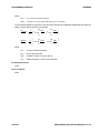
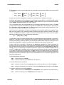
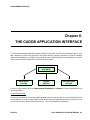
2.2. MAJOR FUNCTIONAL CODE BLOCKS
Figure 3 presents a grouping of source code blocks within the ASTROS system. This grouping is functional in that code related to the performance of one task or a series of tasks at the same level relative to
the executive system are grouped together. According to this breakdown, there are seven major blocks of
code within ASTROS executable programs. The SYSGEN program has no executive system and is
directed by a simple FORTRAN driver called SYSGEN. The ASTROS system, on the other hand, has a
2-4 ASTROS SOFTWARE DESCRIPTION
ASTROS
PROGRAMMER’S MANUAL
highly developed executive system that comprises this major ASTROS code block. Also shown are the five
groups of routines which are used by the SYSGEN and ASTROS programs.
The naming conventions used within each code block are worthy of some discussion since they are useful
in identifying an unknown routine in a piece of ASTROS software. Whenever possible, a set of consistent,
meaningful mnemonics was adopted to identify groups of code that belong together, either functionally or
logically. Where such conventions have been adopted, they are indicated in the discussion of the code
block. One complication to such conventions is the use of existing source code as a resource for the
ASTROS program. When major code units were used from existing software, the convention was not
typically enforced. As a result, there are exceptions to the nomenclatures adopted in some of the source
code blocks presented in this section.
Each of the source code blocks is now briefly discussed by reference to the name assigned to it in Figure 3
and its related Programmer’s Manual section is indicated.
1. SYSGEN is a very small code block containing the SYSGEN driver (SYSGEN), a set of four
output routines (xxxOUT) to print the SYSGEN output file and five routine (TIMxxx) that
compute the timing constants for the large matrix utilities. The SYSGEN program has a single
execution path which is documented in Section 3.2.
2. The ASTROS executive is the code block containing the ASTROS main driver program, ASTROS,
and the ASTROS executive system software. The executive system is embodied in the routines
beginning with the mnemonics XQxxxx. In addition to the pure executive system routines, the
executive initialization routines for the database (DBINIT) and the memory manager (MMINIT)
are also located in this code block. Finally, the general initialization routine PREPAS and the
MAPOL compiler software are considered, for the purposes of the Programmer’s Manual, to be
part of the executive system. These routines are documented in Section 5.
3. The DATABASE code block contains all the software related to the application interface to the
database and memory management systems for the ASTROS procedure. This software is further
subdivided into five groups of code that represent the application interface to the database and
memory manager. These groups are:
a. The General Utilities that comprise the database application interface applicable to all
database entity types. These routines are denoted by the mnemonics DBxxxx and are
documented in Section 8.2.
b. The Memory Management Utilities that comprise the application interface to the ASTROS
dynamic memory manager. These routines are denoted by the mnemonics MMxxxx and are
documented in Section 8.3.
c.
The Matrix Utilities that comprise the database application interface applicable to matrix
entities. These routines are denoted by the mnemonics MXxxxx and are documented in
Section 8.4.
d. The Relation Utilities that comprise the database application interface applicable to
relational entities. These routines are denoted by the mnemonics RExxxx and are documented in Section 8.5.
ASTROS
ASTROS SOFTWARE DESCRIPTION 2-5
PROGRAMMER’S MANUAL
UTILITIES
GENERAL (UT)
OTHERS
SYSGEN
SYSGEN (Main)
BDTOUT
ERROUT
MODOUT
RELOUT
CADDB DATABASE
ASTROS EXECUTIVE
ASTROS (Main)
DBINIT
MMINIT
PREPAS
MAPOL
DBTERM
Executive (XQ)
General (DB)
Memory (MM)
Matrix (MX)
Relation (RE)
Unstructured (UN)
MACHINE DEPENDENT
GENERAL (XX)
DATABASE (DBMD)
LARGE MATRIX UTILITIES
APPLICATION MODULES
Partition/Merge
Multiply and Add
Add
Transpose
Decomposition
Forward/Backward
Substitution
MAPOL Addressable Modules
...
...
...
...
...
Figure 2-2. ASTROS Code Blocks
2-6 ASTROS SOFTWARE DESCRIPTION
ASTROS
PROGRAMMER’S MANUAL
e.
The Unstructured Utilities that comprise the database application interface applicable to
unstructured entities. These routines are denoted by the mnemonics UNxxxx and are
documented in Section 8.6.
4. The MACHINE DEPENDENT code block contains all the software in the ASTROS system that
has been designated machine dependent. This software supplies the interface between the host
computer and the ASTROS system. It is further subdivided into two groups of code:
a. The General Utilities, comprising the machine dependent code used throughout the ASTROS system. These routines are denoted by the mnemonics XXxxxx and are documented
in Section 3.1.1.
b. The Database Utilities, comprising the database machine dependent code used primarily
by the database software. These routines are denoted by the mnemonics DBMDxx and are
documented in Section 3.1.2.
5. The UTILITIES code block contains all the machine independent application utilities developed
for the ASTROS system. This software is a suite of functions that are useful in many places in
the code. They have therefore been formalized to the extent that they may be used by any
ASTROS application routine. The majority of these routines are denoted by the mnemonics
UTxxxx with exceptions corresponding to those in-core utilities that came from COSMIC/NASTRAN. These are documented in Section 6.
6. The LARGE MATRIX UTILITIES code block contains the utilities developed for the ASTROS
system to operate on large matrices stored on the ASTROS database (rather than matrices
stored in memory). This software comprises a suite of matrix operations that have been
formalized to the extent that they may be used by any ASTROS application routine and by the
ASTROS executive system. There is no consistent naming convention for these routines since
they have been derived from their COSMIC/NASTRAN counterparts. The utilities are documented in Section 7.
7. The APPLICATION MODULES code block is the largest code block within ASTROS. It contains
the engineering and application modules that support the analysis and optimization features
of the ASTROS system. Each of these modules has been designed to be independent of the other
application modules to the maximum extent possible. Typically, consistent naming conventions
have been used for routines within each module. Because of the disparate code resources that
were used in the development of ASTROS, however, no globally consistent naming convention
was adopted. Section 5 documents each of the modules in the application library.
2.3. CODE COMMON TO ASTROS AND SYSGEN
Since some machines require or can take advantage of an explicit knowledge of which routines are
needed to create an executable image, this section attempts to indicate which portions of the source code
blocks (as grouped in Figure 3) are utilized within the SYSGEN program. With the exception of the
SYSGEN code block, all the illustrated code blocks are used by the ASTROS program. The source code
blocks that are needed, in whole, or in part, by SYSGEN are (1) the SYSGEN code, (2) the DATABASE
code, (3) parts of the MACHINE DEPENDENT code, (4) some of the UTILITIES and (5) parts of the
ASTROS EXECUTIVE.
ASTROS
ASTROS SOFTWARE DESCRIPTION 2-7
PROGRAMMER’S MANUAL
Rather than write and maintain separate code blocks to perform similar functions, SYSGEN makes use
of the suite of general utilities in the UTILITIES CODE BLOCK. The machine dependent code block is
also shared between ASTROS and SYSGEN.
One of the tasks of SYSGEN is to compile and store the standard executive sequence (written in the
MAPOL language) onto the system database. Therefore, the SYSGEN program makes use of the ASTROS EXECUTIVE code block to supply the MAPOL compiler. In addition, the SYSGEN driver must
perform the executive functions to initialize the memory manager and the database. Therefore, the
MMINIT and DBINIT routines from the ASTROS EXECUTIVE code block are also used by SYSGEN.
2-8 ASTROS SOFTWARE DESCRIPTION
ASTROS
PROGRAMMER’S MANUAL
Chapter 3.
SYSTEM INSTALLATION
A software system of the magnitude of ASTROS requires a formal installation of the system on each host
computer. For ASTROS, the installation process can be broken into three distinct phases. In the first
phase, the ASTROS/host interface is defined and the proper machine dependent code is written to create
that interface. The second phase involves the generation of the executable image of the SYSGEN program and its execution. Finally, the ASTROS executable image is generated using the outputs from the
SYSGEN program. The purpose of this section is to document all the machine dependent code in a
generic manner and to indicate which parameters and routines are most likely to be site dependent and
which are truly machine dependent. In the typical case, the system manager at each facility will be given
the machine dependent library for the host system that is to be used. For completeness, however,
sufficient detail is presented to allow someone familiar with the host system to write a new set of
machine dependent code.
Following the formal documentation of the machine dependent interface is a discussion of the SYSGEN
program and its inputs. The SYSGEN program is important in that it provides the advanced analyst/user
with a mechanism to add features to the system. It is also important for system installation in that part
of its output is required before the executable image of the ASTROS procedure can be generated. Again,
in the typical case the user will be given a proper set of SYSGEN outputs but the utility of SYSGEN in
increasing the capabilities of the system makes its complete documentation very useful to the majority of
ASTROS users. Finally, a brief section is included to present the total ASTROS installation in a step by
step manner to give an overall view of the process.
The information presented in these sections serves as a guide to the installation of ASTROS on alternative host machines, but the nature of the machine dependencies make it impossible to anticipate all
contingencies that may arise. The installation of the ASTROS procedure on a new host computer can
therefore be a complex task despite the relatively small number of machine dependent routines.
ASTROS
SYSTEM INSTALLATION 3-1
PROGRAMMER’S MANUAL
3.1. MACHINE DEPENDENT CODE
The machine dependent interface has been designed to minimize the number of routines needed to
complete the connection between ASTROS and the host system. The development of the machine dependent interfaces can be done in a straightforward manner on most machines with more complexity required
for sophisticated interfaces or for alternative host architectures. The typical ASTROS user will not be
willing to perform any but the most rudimentary duplication of the standard, supported installation
dependent interface, although anyone familiar with the host computer system could accomplish the task.
Installation at sites using machines that are much like the ones already supported is fairly simple,
although even the installation of ASTROS on identical host machines can require some modification to
the machine dependent code since some parameters and code are site dependent as well as machine
dependent.
The machine dependent code is separated into two libraries: the general library, denoted by names
starting with XX, and the database machine dependent library, denoted by names starting with DBMD.
The general library consists of timing routines, bit manipulation routines, some character string manipulation routines, a random number generator and a BLOCK DATA subroutine containing a number of
machine and installation dependent parameters. The timing routines and the random number generator
are site dependent in that each facility typically has a library of such routines. The BLOCK DATA contains
such parameters as the open core size, the definition of logical units, output paging parameters and other
site dependent parameters. The remainder of the routines are very simple and typically do not vary
substantially from site to site, although they are different between machines. In some cases, the XX-routines are written in standard FORTRAN and are in the machine dependent library only because some
host systems provide special routines to perform these tasks.
The database machine dependent library (DBMD) is much more complex than the general machine dependent library. The complication arises because of the flexibility of the machine dependent interface and
because of the nature of the interface. Unlike the XX library, the DBMD library deals with file structures
and I/O to the host system and with memory management. These issues are highly machine dependent
and are further complicated because the translation of machine independent parameters like file names
to the actual host system file name may need to be very flexible depending on the nature of the local host
system. The ASSIGN DATABASE entry in ASTROS allows the user to enter machine dependent parameters associated with the data base file attachment. A major task in writing the DBMD library is the
definition of these parameters and the rules for their use: in general they are used to enable the user to
modify the default file attributes. For example, block sizes; or their location on a physical device, such as
disk volume. The flexibility inherent in the machine dependent interface can cause difficulties in writing
the DBMD code, however, in that the code developer may find it hard to differentiate those aspects of the
interface that are free to be redefined from those that are required by ASTROS. In the authors’ experience, however, the task has proven to be tractable for all host systems used thus far by using the existing
routines as a model. The reader should be under no illusion, however, that the task of writing the DBMD
machine dependent library is simple.
The following sections document the XX and DBMD machine dependent libraries in a machine independent
manner. Each routine that is essential to the ASTROS interface, its calling sequence and its design
requirements is listed. It is very important to appreciate that the actual machine dependent interface
may require additional routines that are not documented in these sections. The only routines that are
3-2 SYSTEM INSTALLATION
ASTROS
PROGRAMMER’S MANUAL
shown here are those that are referenced by the machine independent portions of ASTROS. By definition,
it is these routines that constitute the machine dependent interface. It is often desirable and sometimes
necessary for the machine dependent code to call other machine dependent routines. These internal
interfaces are not documented in this report because of their high degree of dependence on particular
host machines and/or site configurations. It is completely up to the discretion of the code developer to
decide whether such routines are desirable and what tasks they should perform. In fact, there are no
requirements of any kind for the machine dependent code except those imposed by the definition of the
interface (calling sequence and design assumptions). It is that very flexibility that makes the machine
dependent code generation difficult.
3.1.1. General Dependent Code
The following sections document each of the general machine dependent routines contained in the XX
library. These routines tend to be highly site dependent as well as machine dependent, but are relatively
straightforward to develop. Their functions are simple and do not deal with the major machine dependencies like I/O and word sizes.
ASTROS
SYSTEM INSTALLATION 3-3
DOUBLE
PROGRAMMER’S MANUAL
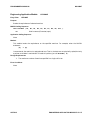
Machine Dependent Utility Module:
Entry Point:
DOUBLE
DOUBLE
Purpose:
Machine dependent logical function to determine the machine precision as one of single or double
precision.
MAPOL Calling Sequence:
None
Application Calling Sequence:
DOUBLE ( )
Method:
DOUBLE returns a .TRUE. if the machine precision is double or a .FALSE. if it is single. ASTROS then
produces all matrix entities and assumes that all matrix entities are of the machine precision. Mixing
single and double precision matrices is not supported by ASTROS code. DOUBLE should be used by all
application modules that use matrix entities.
Design Requirements:
1. All matrix operations must be either single or double, not mixed.
Error Conditions:
None
3-4 SYSTEM INSTALLATION
ASTROS
PROGRAMMER’S MANUAL
Machine Dependent Utility Module:
Entry Point:
XXBCLR
XXBCLR
XXBCLR
Purpose:
Machine dependent integer function to clear a bit in an array.
MAPOL Calling Sequence:
None
Application Calling Sequence:
XXBCLR ( ARRAY, BIT )
Method:
The bit manipulation routines all assume that the BIT identifier can vary from 1 to any positive integer.
A consistent set of assumptions on the correspondence of BIT to a word/bit combination in ARRAY must
be made for all bit routines.
Design Requirements:
1. For machine independent use, application program units should size ARRAY based on 32 or fewer
bits per word.
Error Conditions:
None
ASTROS
SYSTEM INSTALLATION 3-5
XXBD
PROGRAMMER’S MANUAL
Machine Dependent Utility Module:
Entry Point:
XXBD
XXBD
Purpose:
A block data subroutine to initialize machine or installation dependent parameters.
MAPOL Calling Sequence:
None
Application Calling Sequence:
None
Method:
The XXBD block data establishes the values of machine dependent constants. These parameters include
any constant that may be needed for the machine dependent library as well as the following installation
or machine dependent values required by the ASTROS machine independent routines:
1. The size of the open core common block /MEMORY/ in single precision words.
2. System dependent precision terms for the large matrix utilities and memory management
3. The parameters identifying the name and password of the ASTROS system database. These must
correspond to those used in the SYSGEN program.
4. The number of bytes and bits in a single precision word, the number of characters that will be stored
in a hollerith word and the FORTRAN format statement to read or write one hollerith word.
5. The set of "large" and "small" numbers for the machine, including a large real number, a small real
number, the square root of a small real number and the largest integer value supported by the host
system.
6. The installation dependent number of lines per page and the maximum number of output lines that
will be used by the ASTROS page utility, UTPAGE.
7. The ASTROS and SYSGEN version and release identifiers.
8. The installation dependent set of logical unit numbers identifying the read/write/punch units and
the unit to be used for the include files, intermediate storage of the executive timing summary and
the queued storage of the error messages.
9. System dependent null values for relational entity attribute types
Design Requirements:
1. The logical units specified in the XXBD block data must not conflict with those identified in the
database machine dependent block data DBBD for the database files.
Error Conditions:
None
3-6 SYSTEM INSTALLATION
ASTROS
PROGRAMMER’S MANUAL
Machine Dependent Utility Module:
Entry Point:
XXBSET
XXBSET
XXBSET
Purpose:
Machine dependent routine to set a bit in an array.
MAPOL Calling Sequence:
None
Application Calling Sequence:
CALL XXBSET ( ARRAY, BIT )
Method:
The bit manipulation routines all assume that the BIT identifier can vary from 1 to any positive integer.
A consistent set of assumptions on the correspondence of BIT to a word/bit combination in ARRAY must
be made for all bit routines.
Design Requirements:
1. For machine independent use, application program units should size ARRAY based on 32 or fewer
bits per word.
Error Conditions:
None
ASTROS
SYSTEM INSTALLATION 3-7
XXBTST
PROGRAMMER’S MANUAL
Machine Dependent Utility Module:
Entry Point:
XXBTST
XXBTST
Purpose:
Machine dependent logical function to test a bit in an array.
MAPOL Calling Sequence:
None
Application Calling Sequence:
XXBTST ( ARRAY, BIT )
Method:
The bit manipulation routines all assume that the BIT identifier can vary from 1 to any positive integer.
A consistent set of assumptions on the correspondence of BIT to a word/bit combination in ARRAY must
be made for all bit routines.
Design Requirements:
1. For machine independent use, application program units should size ARRAY based on 32 or fewer
bits per word.
Error Conditions:
None
3-8 SYSTEM INSTALLATION
ASTROS
PROGRAMMER’S MANUAL
Machine Dependent Utility Module:
Entry Point:
XXCLOK
XXCLOK
XXCLOK
Purpose:
Machine dependent routine to return the time of day as a character string and as a number of seconds
past midnight.
MAPOL Calling Sequence:
None
Application Calling Sequence:
CALL XXCLOK ( TIME, ISEC )
TIME
Character string containing the time of day as HH:MM:SS (Character, Output)
ISEC
Integer number of seconds since midnight. (Integer, Output)
Method:
None
Design Requirements:
None
Error Conditions:
None
ASTROS
SYSTEM INSTALLATION 3-9
XXCPU
PROGRAMMER’S MANUAL
Machine Dependent Utility Module:
Entry Point:
XXCPU
XXCPU
Purpose:
Machine dependent routine to return the elapsed CPU time in seconds.
MAPOL Calling Sequence:
None
Application Calling Sequence:
CALL XXCPU ( CPU )
CPU
Number of seconds of CPU time used since the job started. (Real, Output)
Method:
On the first call to XXCPU, the utility must initialize the system CPU timer and return 0.0 elapsed
seconds. On subsequent calls, the elapsed CPU time in seconds is returned.
Design Requirements:
None
Error Conditions:
None
3-10 SYSTEM INSTALLATION
ASTROS
PROGRAMMER’S MANUAL
Machine Dependent Utility Module:
Entry Point:
XXDATE
XXDATE
XXDATE
Purpose:
Machine dependent routine to return the date as a character string MM/DD/YY.
MAPOL Calling Sequence:
None
Application Calling Sequence:
CALL XXDATE ( TODAY )
TODAY
Character string containing the date as MM/DD/YY. (Character, Output)
Method:
None
Design Requirements:
None
Error Conditions:
None
ASTROS
SYSTEM INSTALLATION 3-11
XXFLSH
PROGRAMMER’S MANUAL
Machine Dependent Utility Module:
Entry Point:
XXFLSH
XXFLSH
Purpose:
Machine dependent routine to flush any data in the buffer for a given logical unit.
MAPOL Calling Sequence:
None
Application Calling Sequence:
CALL XXFLSH ( LU )
LU
The logical unit number of the file whose buffer is to be flushed. (Integer,
Input)
Method:
The XXFLSH routine will typically be a return. On machines that support the ability to flush the I/O
buffer for a file, however, the XXFLSH routine should call that routine to flush the buffer to the file.
Design Requirements:
None
Error Conditions:
None
3-12 SYSTEM INSTALLATION
ASTROS
PROGRAMMER’S MANUAL
Machine Dependent Utility Module:
Entry Point:
XXINIT
XXINIT
XXINIT
Purpose:
Machine dependent routine to perform general machine dependent initialization tasks.
MAPOL Calling Sequence:
None
Application Calling Sequence:
CALL XXINIT
Method:
The XXINIT routine is typically used to enter machine dependent parameters relating to error handling
by the host machine, the initialization of the machine dependent parameters that must be done at run
time on certain machines and performing any other machine or installation dependent actions that may
be useful. The XXINIT routine is called by the ASTROS main driver as the first executable statement
of the ASTROS.
Design Requirements:
None
Error Conditions:
None
ASTROS
SYSTEM INSTALLATION 3-13
XXITOS
PROGRAMMER’S MANUAL
Machine Dependent Utility Module:
Entry Point:
XXITOS
XXITOS
Purpose:
Machine dependent routine to return the character representation of an integer.
MAPOL Calling Sequence:
None
Application Calling Sequence:
CALL XXITOS ( N, V )
N
Input integer
V
Output character string
Method:
This routine may be written in standard FORTRAN 77 using the internal file feature to write the integer
onto the character string. It is often more efficient to crack the integer into its constituent digits. Some
machines have local utilities that may be used.
Design Requirements:
None
Error Conditions:
None
3-14 SYSTEM INSTALLATION
ASTROS
PROGRAMMER’S MANUAL
Machine Dependent Utility Module:
Entry Point:
XXLSFT
XXLSFT
XXLSFT
Purpose:
Machine dependent integer function to shift bits to the left in an integer word.
Function Arguments:
XXLSFT ( INT, NBIT )
INT
Input integer
NBIT
Integer number of bits to shift left
Method:
The machine independent use of this function requires that NBIT be less than the smallest number of
bits in a word for any target machine (typically 32).
Design Requirements:
None
Error Conditions:
None
ASTROS
SYSTEM INSTALLATION 3-15
XXNOT
PROGRAMMER’S MANUAL
Machine Dependent Utility Module:
Entry Point:
XXNOT
XXNOT
Purpose:
Machine dependent integer function that returns the complement of INT.
MAPOL Calling Sequence:
None
Application Calling Sequence:
XXNOT ( INT )
INT
Input integer
Method:
None
Design Requirements:
None
Error Conditions:
None
3-16 SYSTEM INSTALLATION
ASTROS
PROGRAMMER’S MANUAL
Machine Dependent Utility Module:
Entry Point:
XXOVFL
XXOVFL
XXOVFL
Purpose:
Machine dependent routine to test for floating point overflow or underflow and return a flag denoting
which has occurred.
MAPOL Calling Sequence:
None
Application Calling Sequence:
CALL XXOVFL ( J )
J
Integer value returned based on the over/underflow condition:
= 1 floating point overflow exists
= 2 no error condition
= 3 floating point underflow exists
Method:
In the case of this special routine, if the host system does not have an XXOVFL type of routine, it is
necessary to return a J=2 value for all calls to XXOVFL. In this case, the host system will be relied upon
to indicate the occurrence of a floating point error.
Design Requirements:
None
Error Conditions:
None
ASTROS
SYSTEM INSTALLATION 3-17
XXRAND
PROGRAMMER’S MANUAL
Machine Dependent Utility Module:
Entry Point:
XXRAND
XXRAND
Purpose:
Machine dependent function that returns a random single precision number between 0.0 and 1.0.
MAPOL Calling Sequence:
None
Application Calling Sequence:
XXRAND ( )
Method:
Returns uniformly distributed random numbers.
Design Requirements:
None
Error Conditions:
None
3-18 SYSTEM INSTALLATION
ASTROS
PROGRAMMER’S MANUAL
Machine Dependent Utility Module:
Entry Point:
XXRSFT
XXRSFT
XXRSFT
Purpose:
Machine dependent integer function to shift bits to the right in an integer word.
MAPOL Calling Sequence:
None
Application Calling Sequence:
XXRSFT ( INT, NBIT )
INT
Input integer
NBIT
Integer number of bits to shift right
Method:
The machine independent use of this function requires that NBIT be less than the smallest number of
bits in a word for any target machine (typically 32).
Design Requirements:
None
Error Conditions:
None
ASTROS
SYSTEM INSTALLATION 3-19
XXRTOS
PROGRAMMER’S MANUAL
Machine Dependent Utility Module:
Entry Point:
XXRTOS
XXRTOS
Purpose:
Machine dependent routine to return the character representation of a real number.
MAPOL Calling Sequence:
None
Application Calling Sequence:
CALL XXRTOS ( REL, STR )
REL
Input real number
STR
Output character string
Method:
This routine may be written in standard FORTRAN 77 using the internal file feature to write the real
onto the character string. It is often more efficient to crack the real into its constituent digits. Some
machines have local utilities that may be used.
Design Requirements:
None
Error Conditions:
None
3-20 SYSTEM INSTALLATION
ASTROS
PROGRAMMER’S MANUAL
Machine Dependent Utility Module:
Entry Point:
XXULNS
XXULNS
XXULNS
Purpose:
Machine dependent routine to return the used length of a character string.
MAPOL Calling Sequence:
None
Application Calling Sequence:
CALL XXULNS ( STR, ULEN )
STR
Character string (Character, Input)
ULEN
The position of the last nonblank character (the first character in the string is
character 1). (Integer, Output)
Method:
The XXULNS routine may be written in standard FORTRAN 77 using the LEN function to return the
total length and then looking backwards for the first nonblank character. Certain hosts may benefit
from a machine dependent approach when byte operations are expensive.
Design Requirements:
None
Error Conditions:
None
ASTROS
SYSTEM INSTALLATION 3-21
XXULNS
PROGRAMMER’S MANUAL
3.1.2. Database Dependent Code
The following sections document each of the database machine dependent routines contained in the DBMD
library. These routines tend to be site independent, but are highly machine dependent. Their development on a new host system can become quite complex depending on the desired sophistication of the
interface. These routines deal with file structures I/O and memory management as well as certain CPU
critical string manipulation functions.
3-22 SYSTEM INSTALLATION
ASTROS
PROGRAMMER’S MANUAL
Machine Dependent Utility Module:
Entry Point:
DBMDAB
DBMDAB
DBMDAB
Purpose:
To abort the execution of ASTROS due to a database or memory management fatal error.
MAPOL Calling Sequence:
None
Application Calling Sequence:
CALL DBMDAB
FLAG
( FLAG )
An integer input denoting whether the executive termination utility XQENDS
is to be called or not.
= 0, call XQENDS, otherwise stop
Method:
The DBMDAB routine is set up to avoid the recursion that can occur due to the termination actions taken
by the XQENDS termination utility. Since the database and memory manager are calling for the abort,
the XQENDS routine’s attempts to close the database files often cause the DBMDAB routine to be called
again. Hence, the flag argument is input to denote that the abort condition is such that any attempts
to close the database will cause recursion.
Design Requirements:
None
Error Conditions:
None
ASTROS
SYSTEM INSTALLATION 3-23
DBMDAN
PROGRAMMER’S MANUAL
Machine Dependent Utility Module:
Entry Point:
DBMDAN
DBMDAN
Purpose:
Machine dependent integer function that returns the logical AND of INT1 and INT2.
MAPOL Calling Sequence:
None
Application Calling Sequence:
DBMDAN ( INT1, INT2 )
INT1
Input integer
INT2
Input integer
Method:
None
Design Requirements:
None
Error Conditions:
None
3-24 SYSTEM INSTALLATION
ASTROS
PROGRAMMER’S MANUAL
Machine Dependent Utility Module:
Entry Point:
DBMDCH
DBMDCH
DBMDCH
Purpose:
To convert a character variable of arbitrary length into an integer array with four hollerith characters
per word.
MAPOL Calling Sequence:
None
Application Calling Sequence:
CALL DBMDCH ( CVAR, IVAR, LEN )
CVAR
An input character variable of arbitrary length
IVAR
The output integer array containing the hollerith equivalent of CVAR
LEN
An input integer denoting the number of characters to be placed in IVAR. LEN
should always be a multiple of four, this routine pads with blanks as needed.
Method:
The DBMDCH routine is used extensively by the database routines to convert user supplied character
variables into hollerith integers for subsequent processing. It is critical for performance that this routine
be efficient. For implementation purposes, it must be assumed that the input character string can be
of any length, but the output hollerith variable must always have four characters per word. Any extra
bytes left unused are filled with blanks.
The only way standard FORTRAN provides to convert character data to hollerith data is with an incore
file operation using the FORTRAN read. While this method works on all machines, it is typically very
slow and causes severe performance penalties. This method can be avoided in most cases since compilers
typically pass two arguments for every character variable with the virtual argument containing the
character length. The virtual argument either follows the character argument directly or is passed at
the end of the list of actual arguments. Knowing this, this routine can usually be written using all integer
data thereby producing much faster code.
Design Requirements:
None
Error Conditions:
None
ASTROS
SYSTEM INSTALLATION 3-25
DBMDC1
PROGRAMMER’S MANUAL
Machine Dependent Utility Module:
Entry Point:
DBMDCX
DBMDC1
Purpose:
To perform phase 1 of database configuration initialization.
MAPOL Calling Sequence:
None
Application Calling Sequence:
CALL DBMDC1 ( NWORD )
Number of words required in DBNT (Integer, Output)
NWORD
Method:
Phase 1 of the database configuration normally involves the determination of default values for the
database. The values that can be changed are defined in the /DBCONS/ common block. These values
can be hard coded in this routine, hard coded in the DBBD block data routine or read from a configuration
file.
The only required function of the routine is to return the number of words in the system dependent
portion of the DBNT.
Design Requirements:
None
Error Conditions:
None
Entry Point:
DBMDC2
Purpose:
To perform phase 2 of database configuration initialization.
MAPOL Calling Sequence:
None
Application Calling Sequence:
CALL DBMDC2 ( DBNT )
DBNT
Database name table (Integer, Input)
3-26 SYSTEM INSTALLATION
ASTROS
PROGRAMMER’S MANUAL
DBMDC2
Method:
When phase 2 of the database configuration is performed, the DBNT table has been allocated and partially
initialized. This routine must initialize the system dependent portion of the table. The location of this
data can be found as follows.
DBENTSD
= Z (DBNT + DBNSD)
Z(DBENTSD + xx) = machine dependent data
It is also the responsibility of this routine to make sure that all of the following variables in /DBCONS/
have legal values.
DBDFIL
default number of data files
DBMFIL
maximum number of data files
DBDEFD
default data file block size
DBDEFI
default index file block size
DBMAXE
maximum number of ENT entries
DBMAXD
maximum number of DBNT entries
DBMAXN
maximum number of NST entries
DBALGN
required buffer alignment
Design Requirements:
None
Error Conditions:
None
ASTROS
SYSTEM INSTALLATION 3-27
DBMDDT
PROGRAMMER’S MANUAL
Machine Dependent Utility Module:
Entry Point:
DBMDDT
DBMDDT
Purpose:
To return the time and date in hollerith formats.
MAPOL Calling Sequence:
None
Application Calling Sequence:
CALL DBMDDT ( DATE, TIME )
DATE
Date in form MM/DD/YY (2 integer words, output)
TIME
Time in form HH:MM:SS (2 integer words, output)
Method:
This subroutine should return the current date and time in the appropriate locations. Each value
returned should be stored in two integer words with four hollerith characters per word.
Design Requirements:
None
Error Conditions:
None
3-28 SYSTEM INSTALLATION
ASTROS
PROGRAMMER’S MANUAL
Machine Dependent Utility Module:
Entry Point:
DBMDER
DBMDER
DBMDER
Purpose:
To handle machine and installation dependent error conditions for the database and memory manager.
MAPOL Calling Sequence:
None
Application Calling Sequence:
CALL DBMDER ( ERROR )
ERROR
A character argument containing an error message identifier.
Method:
The DBMDER routine is intended to be used in two ways. The first, denoted by a blank character string
on input, is to activate any machine dependent error handling. This is the interface to the DBMDER
routine from the machine independent library. For example, the DBMDER routine typically invokes the
host dependent mechanism to obtain a traceback to assist in locating the source of an error. The second
interface, using nonblank character strings on input, is intended for use by the machine dependent
(DBMD) library. In this function, the DBMDER routine typically writes out error messages identifying the
nature of the (machine dependent) error condition. This is useful for error checking the file naming
conventions, host I/O limitations, and other host dependent user interfaces to the ASTROS system.
Design Requirements:
None
Error Conditions:
None
ASTROS
SYSTEM INSTALLATION 3-29
DBMDFP
PROGRAMMER’S MANUAL
Machine Dependent Utility Module:
Entry Point:
DBMDFP
DBMDFP
Purpose:
An integer function to reorder the bytes in an integer word.
MAPOL Calling Sequence:
None
Application Calling Sequence:
DBMDFP ( INUM )
INUM
An integer word whose bytes are to be reordered
Method:
On certain machines (notably VAX), the bytes in an integer word are stored in an order right to left.
When hollerith data are used, this feature complicates the comparison of two hollerith words. This
routine is called to reorder the bytes in an integer word to be left to right, independent of the storage
format on the machine. On machines that do not swap bytes, the DBMDFP function value should be set
equal to the INUM value.
Design Requirements:
None
Error Conditions:
None
3-30 SYSTEM INSTALLATION
ASTROS
PROGRAMMER’S MANUAL
Machine Dependent Utility Module:
Entry Point:
DBMDHC
DBMDHC
DBMDHC
Purpose:
To convert an integer array with four hollerith characters per word into a character variable of arbitrary
length.
MAPOL Calling Sequence:
None
Application Calling Sequence:
CALL DBMDHC ( IVAR, CVAR, LEN )
IVAR
The input integer array containing the hollerith characters.
CVAR
An output character variable containing the character representation of the
hollerith IVAR.
LEN
An input integer denoting the number of characters in IVAR to convert and
place in CVAR. LEN should always be a multiple of four, the routine truncates
or pads with blanks as needed.
Method:
The DBMDHC routine is used extensively by the database routines to convert hollerith integer into
character variables for subsequent processing. It is critical for performance that this routine be efficient.
For implementation purposes it must be assumed that the output character string can be of any length
and the input hollerith variable must have four characters per word as generated by DBMDHC.
The only way standard FORTRAN provides to convert hollerith data to character data is with an incore
file operation using the FORTRAN write. While this method works on all machines, it is typically very
slow and causes severe performance penalties. This method can be avoided in most cases since compilers
typically pass two arguments for every character length. The virtual argument either follows the
character argument directly or is passed at the end of the list of actual arguments. Knowing this, this
routine can usually be written using all integer data which produces much faster code.
Design Requirements:
None
Error Conditions:
None
ASTROS
SYSTEM INSTALLATION 3-31
DBMDHX
PROGRAMMER’S MANUAL
Machine Dependent Utility Module:
Entry Point:
DBMDHX
DBMDHX
Purpose:
To dump a portion of memory in a hexadecimal or octal format.
MAPOL Calling Sequence:
None
Application Calling Sequence:
CALL DBMDHX ( ARRAY, LEN )
ARRAY
Input array containing data to be dumped
LEN
Number of single precision words to dump
Method:
If a database error occurs, portions of the in core control tables are dumped to help diagnose the problem.
It is most often desirable to see this data in a combined hex/octal and character format. This routine
usually dumps the desired data in the following form:
OFFH
OFFD ............hex/octal data .....character data
OFFH - hex/octal offset of the data from /MEMORY/
OFFD - decimal offset of the data from /MEMORY/
Design Requirements:
None
Error Conditions:
None
3-32 SYSTEM INSTALLATION
ASTROS
PROGRAMMER’S MANUAL
Machine Dependent Utility Module:
Entry Point:
DBMDI1
DBMDIX
DBMDI1
Purpose:
Phase 1 of database I/O initialization.
MAPOL Calling Sequence:
None
Application Calling Sequence:
CALL DBMDI1 ( NAME, STAT, RW, USRPRM, NFILE, NWORD )
NAME
Database name (Character, Input)
STAT
Database status (OLD, NEW, TEMP, SAVE, or PERM) (Input)
RW
Read/write flag (RO, WO, R/W, Input)
USRPRM
User parameters (Character, Input)
NFILE
Number of data files in database (Integer, Output)
NWORD
Number of words required for each file in DBDB (Integer, Output)
Method:
Phase 1 of the I/O initialization is responsible for determining two values: the number of data files in
the database and the number of system dependent words required for each file in the DBDB. The DBINIT
call is provided with an argument called USRPRM. The contents of this character string are completely
machine dependent and can be used to specify any special processing. Examples of these fields are
provided in Section 1 of the User’s Manual.
The most difficult function of this routine is to determine the number of data files for a database. The
following ways could be used.
1. If the database has a status of NEW or TEMP, the number of data files is either the default or entered
using the USRPRM.
2. If the database has a status of OLD, the number of data files can either be a hard coded value (usually
1) or can be determined by opening files with the appropriate names until an open fails.
For OLD databases this routine should also determine the index and data file block sizes. This can
usually be done by one of the following two methods.
1. Inquire as to the physical attributes of the file to determine the block sizes.
2. Do a sequential read of the first block of the index file and extract the index and data file block sizes
that are stored there.
Design Requirements:
None
Error Conditions:
None
ASTROS
SYSTEM INSTALLATION 3-33
DBMDI2
PROGRAMMER’S MANUAL
DBMDI2
Entry Point:
Purpose:
Phase 2 of database I/O initialization.
MAPOL Calling Sequence:
None
Application Calling Sequence:
CALL DBMDI2 ( DBDB
)
Database Descriptor Block (Integer, Input)
DBDB
Method:
When phase 2 of the database I/O initialization is performed, the DBDB table has been allocated and
partially initialized. This routine must initialize the system dependent portion of the table. There are
also several words in the machine independent portion of the DBDB that must be initialized for each
index and data file. The following code shows how these words are located.
For the Index file:
DBDDBO = DBDB + DBDIFB
For the Data files:
DBDBO = DBDB + DBDDTA + (IFILE-1)*LENDDE
For all files:
DBDBSD = Z(DBDBO+DBDOSD)
Z(DBDB+DBDIBS) = Index file block size in words
Z(DBDB+DBDDBS) = Data file block size in words
Z(DBDB+DBDMDF) = Maximum number of data files
Z(DBDB+DBDONB) = Current number of blocks in the file
Z(DBDB+DBDOMB) = Maximum number of blocks allowed in the file
Z(DBDBSD+XX) = Machine dependent data
This routine will typically do any physical open or assign calls that are required to make all the index
and data files for this database available for processing.
Design Requirements:
None
Error Conditions:
None
3-34 SYSTEM INSTALLATION
ASTROS
PROGRAMMER’S MANUAL
Machine Dependent Utility Module:
Entry Point:
DBMDLC
DBMDLC
DBMDLC
Purpose:
An integer function to provide the memory manager with an address of a character memory location in
particular precisions.
MAPOL Calling Sequence:
None
Application Calling Sequence:
DBMDLC ( BASE, PREC, STAT )
BASE
An input character array whose absolute address is desired.
PREC
An input integer denoting the desired precision of the address
= 0 byte address
= 1 word address
= 2 double precision word address
STAT
An output integer value that is nonzero if any error conditions occurred.
Method:
The routine determines the absolute address of BASE and modifies the offset value to account for the
precision of the desired address. For example, the VAX machine returns the byte address from the system
utility %LOCF. To obtain the word address for the VAX, the byte address is divided by the number of
bytes per word (four). A check is made to determine if the byte address is an even multiple of four and/or
eight to check the single and double word alignment.
Design Requirements:
1. This routine is identical to DBMDLF except that the BASE array in this routine is character rather
than integer.
Error Conditions:
1. On certain machines, there is a requirement that the memory addresses be aligned on single and/or
double word boundaries. This routine should perform these checks and return the proper STAT value
if the required alignments are not met.
ASTROS
SYSTEM INSTALLATION 3-35
DBMDLF
PROGRAMMER’S MANUAL
Machine Dependent Utility Module:
Entry Point:
DBMDLF
DBMDLF
Purpose:
An integer function to provide the memory manager with an address of an memory location in particular
precisions.
MAPOL Calling Sequence:
None
Application Calling Sequence:
DBMDLF ( BASE, PREC, STAT )
BASE
An input integer array whose absolute address is desired.
PREC
An input integer denoting the desired precision of the address
= 0 byte address
= 1 word address
= 2 double precision word address
STAT
An output integer value that is nonzero if any error conditions occurred.
Method:
The routine determines the absolute address of BASE and modifies the offset value to account for the
precision of the desired address. For example, the VAX machine returns the byte address from the system
utility %LOCF. To obtain the word address for the VAX, the byte address is divided by the number of
bytes per word (four). A check is made to determine if the byte address is an even multiple of four and/or
eight to check the single and double word alignment.
Design Requirements:
1. This routine is identical to DBMDLC except that the BASE array in this routine is integer rather than
character.
Error Conditions:
1. On certain machines, there is a requirement that the memory addresses be aligned on single and/or
double word boundaries. This routine should perform these checks and return the proper STAT value
if the required alignments are not met.
3-36 SYSTEM INSTALLATION
ASTROS
PROGRAMMER’S MANUAL
Machine Dependent Utility Module:
Entry Point:
DBMDMM
DBMDMM
DBMDMM
Purpose:
Initializes machine dependent parameters for the memory manager.
MAPOL Calling Sequence:
None
Application Calling Sequence:
CALL DBMDMM ( ICAWA, IWLIC )
ICAWA
An output integer indicating if characters are word aligned on the host machine:
= 0 if character variables are word aligned
= 1 if character variables are not word aligned
IWLIC
An output integer containing the number of characters stored in a single
precision word on the host system.
Method:
None
Design Requirements:
None
Error Conditions:
None
ASTROS
SYSTEM INSTALLATION 3-37
DBMDOF
PROGRAMMER’S MANUAL
Machine Dependent Utility Module:
Entry Point:
DBMDOF
DBMDOF
Purpose:
An integer function to return a FORTRAN index such that the location of one array can be accessed via
another array
MAPOL Calling Sequence:
None
Application Calling Sequence:
DBMDOF ( ARRAY1, ARRAY2 )
ARRAY1
One FORTRAN array (Input)
ARRAY2
Second FORTRAN array (Input)
Method:
The result, DBMDOF, is a FORTRAN index such that the same memory location is referenced by ARRAY1
(DBMDOF) and ARRAY21.. In the DBOPEN call, the user provides a 20-word INFO array. The last 10 words
of this block are available for any required user data. These 10 words can be modified anytime up to the
DBCLOS call for the entity. Since the INFO array is not passed on the DBCLOS call, the DBOPEN call must
remember where it is for later access by the DBCLOS call. The DBMDOF function allows the database to
remember where the INFO block is by saving its location relative to the /MEMORY/ common block at
open time.
The actual implementation of the call usually requires some method for obtaining the actual address
for a subroutine argument.
Design Requirements:
None
Error Conditions:
None
3-38 SYSTEM INSTALLATION
ASTROS
PROGRAMMER’S MANUAL
Machine Dependent Utility Module:
Entry Point:
DBMDOR
DBMDOR
DBMDOR
Purpose:
Machine dependent integer function that returns the logical OR of INT1 and INT2.
MAPOL Calling Sequence:
None
Application Calling Sequence:
DBMDOR ( INT1, INT2 )
INT1
Integer (Input)
INT2
Integer (Input)
Method:
None
Design Requirements:
None
Error Conditions:
None
ASTROS
SYSTEM INSTALLATION 3-39
DBMDRD
PROGRAMMER’S MANUAL
Machine Dependent Utility Module:
DBMDRD
DBMDRD
Entry Point:
Purpose:
To read a block from the database.
MAPOL Calling Sequence:
None
Application Calling Sequence:
CALL DBMDRD ( DBDB, FILE, BLK, BUFHD )
DBDB
Database Descriptor Block (Integer, input)
FILE
File Number (for index files, FILE = 0) (Integer, input)
BLK
Block Number; if FILE < 0 then BLK is IBLK*DBMFIL + FILE
(Integer, input)
BUFHD
The I/O header location (Intger, input)
Method:
The function of this routine is to read a block from the database. The first step is to determine the
database file and block number to be read. the following code will perform this.
IF(FILE .LT. 0) THEN
IBLK = BLK/DBMFIL
IFILE = BLK - IBLK*DBMFIL
ELSE
IBLK = BLK
IFILE = FILE
ENDIF
The block should then be read into the I/O buffer using the appropriate calls for the target system. The
machine independent DBDB data, referenced from DBDBO, and machine dependent DBDB data, referenced
from DBDBSD can be obtained from the buffer header. The number of words to transfer, BLKSIZ, is
obtained from the DBDB.
IF(IFILE .EQ. 0) THEN
DBDBO = DBDB + DBDIFB
BLKSIZ = Z(DBDB+DBDIBS)
ELSE
DBDBO = DBDB + DBDDTA + (IFILE-1)*LENDDE
BLKSIZ = Z(DBDB+DBDDBS)
ENDIF
BUFIO = Z(BUFHD+BFIOBF)
DBDBSD = Z(DBDBO+DBDOSD)
3-40 SYSTEM INSTALLATION
ASTROS
PROGRAMMER’S MANUAL
DBMDRD
After the I/O operation, the following two words of the buffer header should be updated:
Z(BUFHD+BFPBLK) = IBLK*DBMFIL + IFILE
Z(BUFHD+BFDBDB) = DBDB
Design Requirements:
None
Error Conditions:
None
ASTROS
SYSTEM INSTALLATION 3-41
DBMDSI
PROGRAMMER’S MANUAL
Machine Dependent Utility Module:
Entry Point:
DBMDSI
DBMDSI
Purpose:
To return the integer represented by a character string.
MAPOL Calling Sequence:
None
Application Calling Sequence:
CALL DBMDSI ( STR, IVALUE )
STR
An input character string containing digits and signs representing an integer
value.
IVALUE
An output integer variable containing the integer value represented by the
input character string
Method:
This routine is typically written in standard FORTRAN, but may be available as a host system utility.
Design Requirements:
1. A leading + or – sign is permitted as are all the decimal digits. Any other characters are illegal.
Error Conditions:
1. If the character string does not represent an integer, no warnings are given and IVALUE is set to
zero.
3-42 SYSTEM INSTALLATION
ASTROS
PROGRAMMER’S MANUAL
Machine Dependent Utility Module:
Entry Point:
DBMDTR
DBMDTR
DBMDTR
Purpose:
To terminate processing of a database.
MAPOL Calling Sequence:
None
Application Calling Sequence:
CALL DBMDTR ( DBDB )
DBDB
Database Descriptor Block (Integer, Input)
Method:
This routine is called at program termination to do any system dependent termination processing for
each database. It is not required to do anything. Typically it will close all database files.
Design Requirements:
None
Error Conditions:
None
ASTROS
SYSTEM INSTALLATION 3-43
DBMDWR
PROGRAMMER’S MANUAL
Machine Dependent Utility Module:
Entry Point:
DBMDWR
DBMDWR
Purpose:
To write a block to the database.
MAPOL Calling Sequence:
None
Application Calling Sequence:
CALL DBMDWR ( BUFHD )
BUFHD
I/O buffer header location (Integer, Input)
Method:
The function of this routine is to write a block to the database. The processing is similar to DBMDRD and
the same information is available to the routine.
When writing this routine one special case must be considered. Because of the dynamic way in which
database blocks are allocated and used, it can never be assumed that the database blocks are appended
in sequential order. For example block 10 may be written before block 9. If this situation is not allowed
on the target system then this routine should write dummy blocks to fill any gap before writing the
target block. The contents of these dummy blocks is unimportant.
After the I/O operation, the "buffer modified" flag in the buffer header should be set to zero.
Z(BUFHD+BFMOD) = 0
Also, this routine should maintain the word in the machine independent portion of the DBDB which
indicates the number of blocks on the physical file.
Z(DBDBO+DBDONB) = MAX(IBLK,Z(DBDBO+DBDONB))
Design Requirements:
None
Error Conditions:
None
3-44 SYSTEM INSTALLATION
ASTROS
PROGRAMMER’S MANUAL
DBMDZB
Machine Dependent Utility Module:
Entry Point:
DBMDZB
DBMDZB
Purpose:
To find the first zero bit in a word
MAPOL Calling Sequence:
None
Application Calling Sequence:
CALL DBMDZB ( WORD, BITNO )
WORD
Word to be searched for a zero bit (Integer, Input)
BITNO
Bit number found. It will be a number ranging from 1 to 31 if a zero bit was
found. It will be –1 if all 31 bits are on. (Integer, Output)
Method:
The free Block Bit Map (FBBM) uses a bit to represent each block on the particular database file. If the
bit is on, the block is allocated and if the bit is off, the block is unallocated. Each word in the FBBM is
used to represent 31 blocks. The bits are numbered as follows:
unused
01
02
03
...
31
This bit numbering scheme must be maintained regardless of the bit numbering scheme of the target
system.
The DBMDZB routine should return the first zero bit, starting from left to right. If all bits are one, then
a –1 is returned. This function typically uses the FORTRAN BTEST function (if one is provided) with
appropriate calculations to use the proper bit numbering scheme.
Design Requirements:
None
Error Conditions:
None
ASTROS
SYSTEM INSTALLATION 3-45
DBMDZB
PROGRAMMER’S MANUAL
3.2. THE SYSTEM GENERATION PROGRAM
After development of the machine dependent source code for the target host machine, the next step in the
ASTROS system installation is the assembly of the executable image of the ASTROS system generation
program, SYSGEN. The libraries that must be linked to generate this program have been outlined in
Section 2 of this manual while this section discusses the function of the SYSGEN program and details the
structure of its inputs. These inputs not only define the standard ASTROS system but are also a powerful
tool for an advanced user to expand the capabilities of the system. SYSGEN represents one of the most
useful features of the ASTROS system architecture in that it provides for automated modification of
many of the procedure’s capabilities without requiring modification of any existing source code.
The purpose of SYSGEN is to create a system database (SYSDB) defining system parameters through
the interpretation of several input files. Also, a FORTRAN routine is written by SYSGEN that provides
the link between the ASTROS executive system and the application modules that comprise the run-time
library of the procedure. This program unit is then linked with the system during the assembly of the
ASTROS executable image. The resultant procedure makes use of the system database as a pool of data
that defines the system at run time. These data are
1. the contents of the ASTROS run-time library of MAPOL addressable modules including both
utility and application modules, usually delivered as MODDEF.DAT or MODDEF.DATA;
2. the ASTROS standard executive sequence composed of MAPOL source code statements, usually
delivered as MAPOLSEQ.DAT or MAPOLSEQ.DATA;
3. the set of bulk data entries interpretable by the system and defined through the specification
of bulk data templates to be interpreted by the ASTROS Input File Processor (IFP), usually
delivered as TEMPLATE.DAT or TEMPLATE.DATA;
4. the set of relational schemata used by the executive system to satisfy the declaration of relational
variables in the MAPOL sequence without forcing the user to explicitly define each schema at
run time, usually delivered as RELATION.DAT or RELATION.DATA; and
5. the set of error message texts from which the UTMWRT system message writer utility builds error
messages at run time, usually delivered as SERRMSG.DAT or SERRMSG.DATA.
There is an input file for each of these data which is interpreted by SYSGEN and used to write data to
SYSDB in particular formats. These database entities are then used by the ASTROS executive system,
application modules and utilities to perform certain functions. Since these program units are designed to
interpret the set of data that are present in the SYSDB entities, they are flexible in that virtually any
changes to the set of data can be accommodated without modification of the software that uses the data.
The following sections each contain a description of a SYSGEN input file and of the SYSDB database
entities that are filled with the corresponding data. These input files contain the definition of the system
as developed for the ASTROS procedure. The advanced user may, through the appropriate changes to
these inputs, add new modules, add new error messages that may be useful as part of the additional
module(s), add new bulk data inputs, add new relational schemata to those that exist or add new
attributes to an existing schema. Finally, the standard solution algorithm itself can be modified, either to
include (as a permanent modification) a new feature or to modify an existing capability. The advanced
3-46 SYSTEM INSTALLATION
ASTROS
PROGRAMMER’S MANUAL
DBMDZB
user is cautioned, however, that the standard sequence represents a very tightly interwoven set of
functions and any changes should be carefully considered for their ramifications on the multidisciplinary
features of the system as it is currently defined.
3.2.1. Functional Module Definition
The functional modules form the computational heart of the ASTROS system. A sequential file contains
character data records that define the following information for each module:
1. The name of the module
2. The number of formal parameters
3. If the module is a function or a procedure
4. The type of each formal parameter
5. FORTRAN code lines defining the module call
The purpose of these data is three-fold:
1. To provide the names of modules that are a part of ASTROS
2. To allow the validation of module calls including type checking of the input parameters
3. To define the way in which the results of a module are used and to provide the actual FORTRAN
link to activate a module
The format used to provide these data is described in the following section
3.2.1.1 The File Format
The module definition file is organized as a sequence of module entries.
MODULE1. ENTRY
MODULE2. ENTRY
...
Each module entry has the following form:
MODNAME, NPARM
MODTYPE, PARMTYPE(I)
...
FORTRAN LINES
...
END
(A8,I4)
(20I4)
(A80)
(A8)
where the first line consists of MODNAME and NPARM and the second line consists of MODTYPE and the first
19 PARMTYPEs. The PARMTYPEs continue, 20 per line, on subsequent lines, as required to supply NPARM
PARMTYPEs.
ASTROS
SYSTEM INSTALLATION 3-47
DBMDZB
PROGRAMMER’S MANUAL
The lines following the PARMTYPEs consist of FORTRAN code (including, but not requiring,
comments or blank lines) which implements the module interface to MAPOL.
The last line of a module entry is the word END starting in column 1.
MODNAME
NPARM
MODTYPE
PARMTYPE
is the module name as it appears in MAPOL; 1 to 8 characters beginning
with a letter. The name is left-justified in an 8-character field.
is the number of formal parameters in the calling list of the module. This is
a right-justified integer in a 4-digit field. There is a limit of 50 parameters.
is a four-digit code for the module type:
100 means the module is a function with a fixed number of parameters
101 means the module is a function with a variable number of parameters
102 means the module is a procedure
The declared type of each parameter in the calling list selected from the
following codes, each a four-digit integer:
1
Integer
2
Real
3
Complex
4
Logical
5
Not Used
6
Not Used
7
Relational Entity
8
Matrix Entity
9
Unstructured Entity
10 Real, Integer, or Complex
If the PARMTYPE is entered as a negative value, the parameter is optional. Note that character
PARMTYPEs are not supported.
Procedures
For procedures, a call is made to the ASTROS name with a parameter list having symbolic
arguments of the correct types. For example, if a module has the following parameters (in order)
with the specified data types:
3
Integers
1
Logical
1
Integer
1
Relation
1
Integer
1
Optional integer
1
Optional matrix
1
Matrix
1
Optional matrix
3-48 SYSTEM INSTALLATION
ASTROS
PROGRAMMER’S MANUAL
DBMDZB
1
Logical
1
Matrix
1
Optional matrix
2
Matrices
1
Unstructured
2
Optional matrices
1
Optional logical
2
Optional matrices
1
Optional unstructured
then the call to this routine is coded as:
AROSNSDR 23
102
1
1
1
4
1
7
1 -1 -8
8 -8
4
8 -8
8
8
-4 -8 -8 -9
C
C
PROCESS ’AROSDR’ MODULE - SAERO CONSTRAINT SENS. DRIVER
C
CALL AROSDR ( IP1., IP2., IP3., LP4., IP5., EP6., IP7.,
1
IP8., EP9., EP(10), EP(11), LP(12), EP(13),
2
EP(14), EP(15), EP(16), EP(17), EP(18), EP(19),
3
LP(20), EP(21), EP(22), EP(23) )
END
9
-8
-8
The subscripted array elements are used by the ASTROS executive to pass the actual parameter values.
The subscripts must correspond to the order of the arguments in the MAPOL calling list. The following
array names are used:
IP
RP
CP
LP
EP
–
–
–
–
–
Integer Parameter
Real Parameter
Complex Parameter
Logical Parameter
Entity name
This method passes only scalar parameters to the FORTRAN driver. No mechanism is available to pass
FORTRAN arrays.
Functions
For a function, the resultant value is returned to MAPOL on the execution stack. To accomplish this, the
programmer must assign the numeric function result to the FORTRAN variables IOUT, ROUT, and COUT
that define the number to the executive. This is analogous to a function in FORTRAN, in which the value
must be assigned to the function name within the function unit.
ASTROS
SYSTEM INSTALLATION 3-49
DBMDZB
PROGRAMMER’S MANUAL
A numeric value is defined as follows:
IOUT1.
Variable type key with the same definitions as in PARMTYPE
IOUT(2,3) or
ROUT(2,3) or
COUT
Contain the actual integer, real or complex variable value. These
arrays are all equivalenced:
If the value is integer, only IOUT2. must be defined. If the value is real, only ROUT2. must be defined.
If the value is complex, then either COUT must be defined, or ROUT2. and ROUT3. must be defined. What
is important is that the data in the second and third words be consistent with the type in IOUT1..
Further if the function operation depends on the types of arguments (as do the FORTRAN generic
functions, e.g. MAX, SIN), the array
TP(I), I=1, NPARAM
may be read in the module definition code to determine the type of argument passed. The PARMTYPE
definition should then be 10 to allow any type to be passed. TP uses the same definitions as PARMTYPE,
except the actual type of the argument is stored. In other words, TP contains a 1, 2, or 3 in the location
associated with type 10 parameters, depending on the actual type passed in the current call.
For example, if the sine function is desired, the following module definition would be used:
SIN
1
100 10
C
C
SIN - RETURN THE SINE OF THE ARGUMENT
C
IF( TP1. .LE. 2 ) THEN
IOUT1. = 2
IF ( TP1. .EQ. 1 ) RP1. = IP1.
ROUT2. = SIN(RP1.)
ELSE
IOUT1. = 3
COUT
= SIN(CP1.)
ENDIF
END
3.2.1.2
SYSGEN Output for Modules
The data defined by the module file are processed and the results are stored on the system database in
two entities. The first is a relation called MODINDEX. This relation has two attributes: the first, MODLNAME, is the module name and the second, ARGPONTR, is a pointer to the second entity. This second entity
is called MODLARGS. Each record of this unstructured entity contains the MODTYPE and PARMTYPE data
from the module definition file for a particular module. Additionally, the output of SYSGEN includes a
FORTRAN subroutine called XQDRIV. This routine is the module driver for the ASTROS execution
monitor. It must be compiled and linked into the system when adding or changing module definitions.
3-50 SYSTEM INSTALLATION
ASTROS
PROGRAMMER’S MANUAL
DBMDZB
3.2.2. Standard Solution Algorithm Definition
The standard multidisciplinary solution algorithm, in the form of MAPOL source code statements, is
contained in a sequential file. The SYSGEN program reads this file and compiles a standard sequence.
The results of the compilation are stored on the system database in the form of two relations and an
unstructured entity. The first relation is called &MAPMEM and has three attributes: ADDRESS, VARTYPE,
and CONTENT. This relation stores the execution memory map for the standard MAPOL sequence. ADDRESS is an integer containing the address of the variable, VARTYPE is an integer denoting the variable
type and CONTENT is a two-word integer array containing the current value of the variable.
The second relation output from the compilation of the standard sequence is called &MAPCOD and has
three attributes: INSSEQ, OPCODE, and ARGUMENT. This relation contains the ASTROS machine instructions that represent the compiled MAPOL sequence. INSSEQ is an integer containing the instruction
sequence number, OPCODE is the machine operation code to determine the action to be taken, and
ARGUMENT is the argument to the operation -- either a memory address of an immediate operand.
The final output from the standard algorithm definition is not directly related to the compilation of the
sequence. It is a relation called &MAPSOU containing the standard sequence source code statements
verbatim. This is stored on the system database, allowing the user to edit the standard sequence to
generate a new MAPOL program which directs the ASTROS procedure. The relation has two attributes:
LINENO and SOURCE. LINENO is an integer containing the line number and SOURCE is a string attribute
containing the 80-character source code line.
3.2.3. Bulk Data Template Definition
The ASTROS bulk data decoding module (IFP) is driven by templates that are stored on the system
database during system generation. The template format for IFP was adopted to allow for easy installation of new bulk data entries and for easy modification of existing bulk data entries. The sequential file
used by SYSGEN contains the bulk data templates for all the bulk data inputs defined to the ASTROS
system in arbitrary order.
3.2.3.1
The File Format
The template definition file has the following format:
MAXSET (I8)
NLPTMP (I8)
TEMPLATE 1
TEMPLATE 2
...
...
MAXSET is the maximum number of template sets used to define one bulk data input. Currently, this
value is five. NLPTMP is the number of lines in each template set. Currently there are six lines in each set.
A bulk data template therefore consists of 1,2,3,...MAXSET template sets, each of which consist of
NLPTMP template lines which define the structure of the input entry. The definition includes the field
ASTROS
SYSTEM INSTALLATION 3-51
DBMDZB
PROGRAMMER’S MANUAL
size, the field label, the field data type, the field defaults, the field checks, the field database loading
position and, if necessary, a list of relational attributes. The structure of the template set is as follows:
BULK DATA ENTRY LABEL
FIELD DATA TYPES
DEFAULT VALUES
ERROR CHECKS
FIELD LOADING POSITION
DATABASE ENTITY DEFINITION
A typical bulk data entry template is:
CQUAD4 |EID
CHAR
INT
DEFAULT
CHECKS GT 0
1
CQUAD4 EID
+CQUAD4|
CHAR
DEFAULT
CHECKS
|PID
|G1
INT
INT
EID
GT 0
GT 0
2
3
PID1
GRID1
|TMAX
|T1
REAL
REAL
1.E4
GE 0.
GE 0.
10
11
OFFST0 TMAX
|G2
INT
|G3
INT
|G4
INT
UG 2
4
GRID2
|T2
REAL
UG 3
5
GRID3
|T3
REAL
UG 4
6
GRID4
|T4
REAL
GE 0.
12
THICK1
GE 0.
13
THICK2
GE 0.
-14
THICK3
|TM
|ZOFF
INT/REALREAL
0.
0.
GT 0
7
9
CID1
THETA
|
THICK4
|CONT
CHAR
|
|
$
The LABEL Template Set Line
The first seven columns of the first template set line define the name of the input data entry. The eighth
column is reserved for a field mark, "|". Columns 9 through 72 define the field labels and these are
separated by the field mark "|". Columns 73 through 79 indicate to the decoding routines if a continuation card is supported for this entry. On the first template set’s LABEL line (the template set for the
parent line of the bulk data entry), the character string CONT indicates that a continuation line is
supported. Otherwise, these columns are ignored and a continuation will not be allowed for the entry
defined by this template. A continuation template set’s LABEL line differs from the parent template in
that the character string ETC can be used in columns 73 through 79 of the continuation template set’s
LABEL line to indicate an open ended entry having a repeating continuation. In this case, the same
continuation template will be used to decode all remaining continuation entries. For free format input,
the continuation entries must have the input extend to the third field (the second data field). Also, note
that ALL template set’s LABEL lines must have a field mark in column 80 to end the line.
The FIELD DATA TYPE Template Set Line
The FIELD DATA TYPE Template Set Line defines the types of data that are allowed for each
field. Possible data types include: blank, INT (integer), REAL (real), CHAR (character), INT/REAL (integer
or real), INT/CHAR (integer or character), and REL/CHAR (real or character). The data type definition
characters (i.e., INT) must be left justified in the fields.
3-52 SYSTEM INSTALLATION
ASTROS
PROGRAMMER’S MANUAL
DBMDZB
The DEFAULT Template Set Line
The DEFAULT template set line defines the default values of the fields. If the input data entry has an
empty field, the default value will be used as the input. All values, like the data types, must be left
justified in the fields. Three special cases for default values have been incorporated into the decoding
routines. The first is the case of a special user input entry to define the defaults for a template. In this
case the user supplied values will be substituted for the normal default values. The BAROR and GRDSET
entries are examples of special inputs used to define the defaults. The addition of any other special inputs
like these requires program changes in routines IFPBD, BDMERG, and IFPDEC. Another special case is in
the referral to another field of the same template to obtain the default value. Referral values can exist for
all data types except character (CHAR) data. In the case of a default referral, the current template set
LABEL line is searched for the label referred to and, if the label string is not found, all other template
sets, starting at the parent template set, are searched for the string. When the string is found, the
corresponding entry field is decoded to obtain the default value. An example of a referral is the PID field
of the CQUAD4 card template. The third special case for defaults is the use of a multiplier for an integer
default referral. This is only valid for integer type data and the presence of a multiplier is defined by an
asterisk "*". For example, 3*NDN, where NDN is the label associated with another integer data field.
The ERROR CHECK Template Set Line
The ERROR CHECK template set line directs data checking for the decoded fields. Each error check
specifies both the type of check and the check value. The available check types depend on the data type
(for example, Integer, Real, or Character). Checks that are currently encoded are shown in Table 1.
If additional checks are needed, subroutine INTCHK must be modified for integer checks, RELCHK must be
modified for real checks and CHRCHK must be modified for character checks.
When two check values are needed, as for the IB and EB checks, the first is located on the ERROR CHECK
template set line and the second is located in the same column position on the FIELD LOADING POSITION line.
The FIELD LOADING POSITION Template Set Line
The FIELD LOADING POSITION template set line is used to place the converted data into the database
loading array. The sequence of the numbering is dependent on three conditions. The first is the existence
of CHAR data on the card. In this case, two hollerith single precision words will be used to store an eight
character input and the numbering must account for the two words. The second condition is the sequence
of the attribute list for a relational bulk database entity. In this case the loading sequence is determined
by the sequence of the attribute list. The third condition occurs when a multiple data type field is
present, (e.g., REL/CHAR). In this case the first variable type is loaded at the given value and the second
variable type is loaded in the next word(s). Again this must be accounted for in the numbering sequence.
Finally, when a negative integer value is given as the loading position, the database loading array will be
loaded onto the database if input errors have not occurred. A negative value should be used on the field
associated with the last attribute of the relational projection. At least one negative loading position must
be defined.
ASTROS
SYSTEM INSTALLATION 3-53
DBMDZB
PROGRAMMER’S MANUAL
Table 3-1. Bulk DataTemplate Error Checks
CHECK
TYPE
DATA
TYPE
blank
GT
GE
NE
LT
LE
EQ
EB
IB
EOR
G EP
UG
EUG
COMP
MID3
MID4
SA
EIGG
all
Int,Real
Int,Real
Int,Real
Int,Real
Int,Real
All
Int,Real
Int,Real
Int,Real
Int,Real
Int
Int
Int
Int
Int
Int
Int
EIGC
Int
I12
MATG
NU
IDES
F.T.
YORN
PTYP
ETYP
Int
Int
Real
Real
Char
Char
Char
Char
NORM
Char
CMETH
RMETH
L.O.
Char
Char
Char
ACMP
Char
BCMP
Char
BTYP
Char
CONV
Char
CTYP
Char
FMETH
DTYPE
MPREC
MFORM
FFT1
Char
Char
Char
Char
Char
MEANING
No check
Greater than
Greater than or equal
Not equal
Less than
Less than or equal
Equal
Exclusive in between
Inclusive in between
Either or
CHECK
TYPE
DATA
TYPE
FFT2
Char
MASSF
Char
ETYPL
Char
CCI
Int
CCR1
Real
CCR2
Real
CCR3
Real
GTZOB
GEZOB
Int,Real
Int,Real
ULC
Int
LAMCHK
Int
PLYNORS
NEBLK
Int
Char
ETYPC
Char
PTYPC
Char
ETYPS
Char
PTYPS
Char
STYPE
TRIM
UM
Char
Char
Char
TRMACC
Char
SCFPRM
SCFUNIT
VTYPE
DCNTYP
FLTFIT
LAMCHK
Char
Char
Char
Char
Char
Char
Greater than or equal to the previous value
Unique grid
Empty or unique grid
A set of component numbers
PSHELL MID3 material check
PSHELL MID4 material check
SPCADD, MPCADD combination check
Grid check on the EIGI family of input entries
Component check on the EIGI family of input
entries
I12 check on the CBAR entry
E and G check on the MAT1 entry
Check E, G and NU for the MAT1 entry
Design variable range check
Failure theory for the PCOMP entry
Yes or No
Property type for the PLIST entry
Element type for the ELIST entry
Normalization method for the EIGi family of
input entries
Solution method for the EIGC entry
Solution method for the EIGR entry
Lamination option for PCOMPi entries
Component type for airfoil and CAERO6
entries
Component type for BODY and PAERO6
entries
Body orientation type for the PAERO6 entry
Conversion factor quantity type for the
CONVERT entry
Upper or Lower bound constraint check for
DCONXXX, entries
Flutter analysis method for the flutter entry
Damping type for the TABDMP1 entry
Matrix precision for DMI and DMIG entries
Matrix form for DMI and DMIG entries
Interpolation method for the FFT entry
3-54 SYSTEM INSTALLATION
MEANING
Output format selector for the FFT entry
Mass matrix form option for the MFORM
entry
Element name for the ELEMLIST and
DCONTHK entries
Material property defaulting check for the
PCOMP entry
Laminae thickness defaulting check for the
PCOMP entry
Laminae orientation angle defaulting check
for the PCOMP entry
Laminae orientation angle and thickness
defaulting check for PCOMP1 and PCOMP2
entry
Greater than zero or blank
Greater than or equal to zero or blank
IUST, ILST, and/or ICAM check for the
AIRFOIL entry
DCONLAM/DCONLMN laminate definition
check
DCONLAM/DCONPMN ply definition check
Not equal to blank
Element name for the DCONFTP and
DCONTWP entries
Property name for the DCONFTP and
DCONTWP entries
Element name for the DCONEP and
DCONVM entries
Property name for the DCONEPP and
DCONVMP entries
Control surface symmetry type
TRIM type
UM flag for RBEi entries
Acceleration label check for DCONSCF
entry
Parameter label check for DCONSCF entry
Unit label check for DCONSCF entry
Velocity type check for DCONFLT entry
Constraint type check for DCONLIST entry
Curve fit type check for FLUTTER entry
DCONLAM/DCONLMN laminate check
ASTROS
PROGRAMMER’S MANUAL
DBMDZB
The DATABASE ENTITY DEFINITION Template Set Line
The DATABASE ENTITY DEFINITION template set line names the database entity to be loaded in the
first eight columns of the parent template set, and the database attribute list for relational entities
(Columns 9-72), of the parent template set. Column 80 is reserved for a map-end character ($). The
map-end character indicates the end of the template, and so must occur only on the last database entity
definition line for the final set of the template.
3.2.3.2
SYSGEN Output for Template Definitions
The SYSGEN outputs consist of an unstructured entity called SYSTMPLT which contains the templates
and a relation called TMPPOINT which allows efficient access to particular templates. The SYSTMPLT
entity contains one RECORD for each bulk data template in the order it appears in the input template
definition file. Therefore, the RECORDs are of variable length with the longest RECORD containing 80
characters for each of MAXSET template sets of NLPTMP lines. The TMPPOINT relation has two attributes:
CARD and RECORD. CARD is an eight character string attribute containing the name of the bulk data entry
and RECORD is the number where the template is stored in SYSTMPLT.
3.2.4. Relational Schema Definition
Each relational database entity requires a SCHEMA that defines its data attributes. A sequential file,
containing character data, is used to define these schemata. For each relation there is a list of the
attribute names, their types, and, if they are arrays or character data, their length. The details of this file
are described below:
3.2.4.1
The File Format
The schema definition file is organized as shown below:
REL1. ENTRY
REL2. ENTRY
...
...
REL(NREL) ENTRY
Each RELATION entry has the following form of free field input. Each input may appear anywhere on the
line separated by one or more blanks except "RELATION" and "END".
RELATION RELNAME
ATTRNAME ATTRTYPE ATTRLEN
END
where
RELATION
RELNAM
ASTROS
is the keyword "RELATION" which signifies that a new RELATION schema
follows. Must begin in column 1.
is the name of the RELATION; it may be one to eight characters beginning
with a letter.
SYSTEM INSTALLATION 3-55
DBMDZB
PROGRAMMER’S MANUAL
ATTRNAME
ATTRTYPE
ATTRLEN
END
3.2.4.2
is the name of the attribute; it may be one to eight characters beginning
with a letter.
is the type of the attribute selected from:
’INT’
Integer
’KINT’
Keyed Integer
’AINT’
Array of Integers
’RSP’
Real, single precision
’ARSP’
Array of real, single precision
’RDP’
Real, double precision
’STR’
Character string
’KSTR’
Keyed character string
is the optional length of the Attribute. If it is of type AINT, ARSP, ARDP,
STR, or KSTR, the length is not optional. For other types, it should be zero or
not present.
is the keyword "END" which signifies the END of the RELATION schema.
SYSGEN Output for Relations
The data defined by the RELATION schema file are processed and the results are stored in two entities on
the system database. The first is a RELATION called RELINDEX. This entity has an attribute RELTNAME
containing the name of the RELATION and an attribute SCHMPNTR which is an integer pointer to an
unstructured entity called RELSCHEM. The RELSCHEM entity contains a list of attribute names, types and
lengths for each RELATION. Each RELATION has one tuple in the RELINDEX RELATION and one RECORD
in the RELSCHEM entity. Each RELSCHEM RECORD consists of a four-word entry for each attribute: two
hollerith words containing the attribute name, one hollerith word containing the attribute type and an
integer word containing the attribute length.
3.2.5. Error Message Text Definition
The text of ASTROS run time messages is stored and maintained on a sequential file which is used
during system generation to create SYSDB entities for use by the ASTROS message writer utility
module. There are two reasons for maintaining the message text on an external file (and on SYSDB).
First, the storage of message text within the functional modules would use a large amount of memory
during execution. Second, storing the messages together in an external file allows for easier maintenance
and aids in avoiding needless duplication in message texts. The messages stored on SYSDB from this file
are used by the ASTROS utility UTMWRT to build error messages during execution.
3-56 SYSTEM INSTALLATION
ASTROS
PROGRAMMER’S MANUAL
3.2.5.1
DBMDZB
The File Format
The message text file is organized as follows:
*MODULE 1 {<header>}
messages
*MODULE 2 {<header>}
messages
*MODULE 3 {<header>}
...
...
*MODULE <n> {<header>}
The header is an optional label of any length or content up to 120 characters that typically would
describe the relationship among the messages for the specified module. In this way, messages that are
logically related (for example, all error conditions from the IFP module) can be grouped together for
simplified maintenance. The module number <n> is a unique integer identifying the base module number
for the group of error messages. It need not be consecutive, which allows for randomly numbered modules.
The format of the message text is as follows:
’message text $ more text $ ...’
the string is enclosed in a single quotation marks because the message will be used as a character string
in a FORTRAN write statement. The $ (dollar sign) is used by the UTMWRT utility to place character
arguments into the string. For example,
’$ ELEMENT $ IS ATTACHED TO SCALAR POINT $.’
would appear for CTRMEM element 100 attached to scalar point 1001:
CTRMEM ELEMENT 100 IS ATTACHED TO SCALAR POINT 1001.
If the user wishes the message to carry over to the next output record, the FORTRAN format RECORD
terminator (/) can be used outside the quotation marks to cause a record advance. For example:
’THIS IS ON LINE 1’/’ THIS IS ON LINE 2.’
Currently there is an implementation limit of 128 characters for the length of the message text after
including the arguments. Further details are given in the documentation for the UTMWRT utility module.
3.2.5.2
SYSGEN Output for Error Message Text
The data in the message file are used to create two system database entities. The first is an indexed
unstructured entity called ERRMSG. This entity contains one line of the message text file in each record.
The second is an unstructured entity called ERMSGPNT which has one record. That record has two words
ASTROS
SYSTEM INSTALLATION 3-57
DBMDZB
PROGRAMMER’S MANUAL
for each module defined in the message file. Those words are the module number <n> and the record
number of the ERRMSG RECORD containing the module header. These are used by the UTMWRT to position
to the proper message text when called.
3.3. GENERATION OF THE ASTROS SYSTEM
Following the execution of the SYSGEN program the system installation proceeds to the generation of
the ASTROS executable image. As indicated in Section 3.2, the SYSGEN program writes a FORTRAN
program called XQDRIV which must be linked with the remainder of the source code to form the ASTROS
system. It is this FORTRAN program which provides the flexible interface between the ASTROS executive and the remainder of the ASTROS modules. To generate the ASTROS system, therefore, it is
essential to execute the SYSGEN program as a first step.
The SYSGEN execution is only required once to generate the standard version of ASTROS. This is the
version that is defined by the delivered set of SYSGEN input files described in Section 3.2. If, however,
the users of the system at a particular installation desire to insert additional modules, the SYSGEN
program must be re-executed to recreate the XQDRIV submodule. The users may also want to modify
other SYSGEN inputs to update the system database to include additional input entries or new relational
schema. These changes also require the re-execution of the SYSGEN program (to update the system
database) but do not require an update of the ASTROS system. For most purposes, only the module
definition file described in Section 3.2.1 requires that the ASTROS executable image be recreated.
3-58 SYSTEM INSTALLATION
ASTROS
PROGRAMMER’S MANUAL
Chapter 4.
EXECUTIVE SYSTEM
The ASTROS executive system, as described in Chapter 3 of the Theoretical Manual, may be viewed as a
stylized computer with four components: a control unit, a high level memory, an execution monitor and
an Input/Output subsystem. The first three components comprise the executive system modules, while
the I/O subsystem is embodied in the database. The modules that form the executive system perform
tasks to establish the ASTROS/host interface, initiate the execution and, upon completion of the MAPOL
instructions, terminate the execution. These modules also compile the MAPOL sequence, if necessary,
and initiate the execution monitor that interprets the MAPOL instructions and guides the execution.
This Chapter documents the modules of the ASTROS executive system.
The typical user of ASTROS need not be familiar with the executive system modules since their execution
path does not have the flexibility that is available for the engineering modules. The executive modules,
however, are important from the viewpoint of the system manager and the program developer for several
reasons. First, problems with the machine dependent library on a new host system often show up during
the executive modules’ initialization tasks. The executive system modules are also important in understanding the treatment of the user’s input data stream. To isolate the use of external files to the
executive system, for example, the PREPAS executive module reads the input data stream and loads those
portions that deal with the MAPOL, Solution Control and Bulk Data packets to the database. The system
manager, therefore, may find it useful to study the nature of the executive modules and their interrelationships to better understand the implementation of the ASTROS architecture.
ASTROS
EXECUTIVE SYSTEM 4-1
ASTROS
PROGRAMMER’S MANUAL
Executive System Module:
Entry Point:
ASTROS
ASTROS
PURPOSE:
ASTROS is the main entry point for the ASTROS procedure. It controls the execution path through the
executive system modules.
MAPOL Calling Sequence:
None
Application Calling Sequence:
None
Method:
The ASTROS routine first sets a flag to tell the executive modules that subsequent calls are associated
with the ASTROS procedure rather than with the SYSGEN program. This flag is required since the
compiler and other executive routines are shared between the two programs and require sightly different
execution paths. The machine dependent initialization routine, XXINIT, is then called to perform the
initialization tasks required on the current host system. The initialization is completed by zeroing the
execution monitor’s stack length, calling the machine independent initialization routine, XQINIT,
labeling the output listing and the starting the timing summary.
The PREPAS module is then called to read the user’s input data stream. On return from PREPAS, the
MAPOL compiler is called if a MAPOL compilation is required. Finally, the execution monitor, XQTMON,
is called to interpret the ASTROS machine instructions representing the compiled MAPOL sequence.
All subsequent activities in the ASTROS execution are controlled by this module until all the MAPOL
instructions have been completed. Upon return from XQTMON, the main driver terminates the execution
by writing the closing label, calling the XQENDS module to close the database, dumping the timing
summary and performing any other closing tasks.
The engineering modules (addressed by the execution monitor) may also terminate the execution of the
system. In these cases, the general application utility module, UTEXIT, is used since this routine
assumes that an error exit has occurred. UTEXIT, however, also calls the XQENDS executive module to
assure clean termination of all executions.
Design Requirements:
None
Error Conditions:
None
4-2 EXECUTIVE SYSTEM
ASTROS
PROGRAMMER’S MANUAL
Executive System Module:
Entry Point:
XQINIT
XQINIT
XQINIT
PURPOSE:
To perform machine independent system initialization tasks.
MAPOL Calling Sequence:
None
Application Calling Sequence:
CALL XQINIT
Method:
This routine completes the page titling information on the TITLE line used by the UTPAGE utility. The
ASTROS version number is placed in TITLE (which is in the /OUTPUT2/ common block) in characters
88 through 107. The current date is obtained using XXDATE and placed in characters 109 to 117. The
page number label is then placed in characters 120 to 121. Thus, the page number itself is left to fit in
characters 123 to 128.
Design Requirements:
None
Error Conditions:
None
ASTROS
EXECUTIVE SYSTEM 4-3
PREPAS
PROGRAMMER’S MANUAL
Executive System Module:
Entry Point:
PREPAS
PREPAS
PURPOSE:
To perform the first pass through the user’s input data stream, to initialize the open core memory
manager and to attach the scratch and system databases.
MAPOL Calling Sequence:
None
Application Calling Sequence:
CALL PREPAS ( MAPFLG, SOLFLG, BLKFLG )
MAPFLG
Integer flag denoting the presence or absence of a MAPOL packet in the input
data stream (Output)
0
if no MAPOL packet
1
if a MAPOL packet exists in the input stream
SOLFLG
Integer flag defined like MAPFLG denoting the presence or absence of a Solution Control packet in the input data stream (Output)
BLKFLG
Integer flag defined like MAPFLG denoting the presence or absence of a Bulk
Data packet in the input data stream (Output)
Method:
This routine performs the first pass over the user’s input data stream, performs actions based on the
ASSIGN DATABASE, DEBUG and MAPOL EDIT command inputs and prepares MAPOL, solution control
and bulk data inputs for access by the appropriate modules. The order of operations is crucial and can
be summarized as follows:
1. The debug packet must be processed first since the debug flags can affect the memory management
system.
2. Immediately following the debug packet, the memory manager must be initialized, and the scratch
(run-time) database (based on the ASSIGN DATABASE entry) and the system database must be
attached, in that order. The order is dictated by the requirement that the memory manager be
available for the DBINIT calls and the scratch database must be allocated before the system
database. The system database must be allocated in order to process the MAPOL packet (which
may apply EDIT operations to the standard MAPOL sequence stored on the system database).
Once the ASSIGN DATABASE and debug packets are processed, the remaining packets could be ordered
in any fashion, but a fixed sequence of MAPOL, solution control and bulk data packets has been imposed.
The procedure used in PREPAS is to read the input stream one 80-character record at a time. The first
nonblank records must be the ASSIGN DATABASE entry. The corresponding records are set aside in
ASNCRD for use after the debug packet is processed. After the ASSIGN DATABASE entry has been
encountered, each input record is read and searched to see if one of the input stream keywords appears
in the first eight characters following the first nonblank character. The keywords are:
1. DEBUG denoting the start of the debug packet
2. MAPOL denoting the start of the MAPOL packet containing a complete new MAPOL sequence
4-4 EXECUTIVE SYSTEM
ASTROS
PROGRAMMER’S MANUAL
PREPAS
3. EDIT denoting the start of the MAPOL packet containing edit commands to be applied to the
standard sequence
4.
SOLUTION denoting the start of the solution control packet
5. "BEGIN_" denoting the start of the bulk data packet. Note the trailing blank after BEGIN and the
absence of the optional BULK keyword.
6. ENDDATA denoting the end of the bulk data packet
7. INCLUDE naming the secondary file from which to read the input
Note that all the keywords except ENDDATA and INCLUDE mark the beginning of a new packet. The
INCLUDE keyword does not change the current packet and ENDDATA marks the end of the valid input.
If the current record is one of the keyword records, flags are set to indicate that a new packet has been
initiated or, for INCLUDE, the include file is opened and processing continues with the new input file
until it is exhausted. Records that are not keyword records are processed as follows:
1. DEBUG packet records are sent to the CRKBUG utility to interpret the debug commands and set the
executive system debug command flags in the /EXEC02/ common and set the other debug command
flags by UTSFLG to activate run time debugs.
2. MAPOL packet records representing a replacement MAPOL sequence are written to the unstructured entity &MAPLPKT for processing in the MAPOL module.
3. MAPOL packet records representing an EDIT of the standard sequence are passed to the MAPEDT
subroutine to be interpreted. The resultant MAPOL sequence is written to the unstructured entity
&MAPLPKT for processing in the MAPOL module.
4. SOLUTION packet records are written to the unstructured entity &SOLNPKT for processing in the
SOLUTION module.
5. Bulk Data packet records are written to the unstructured entity &BKDTPKT for processing in the
IFP module.
Design Requirements:
None
Error Conditions:
1. Input stream does not begin with an ASSIGN DATABASE entry.
2. An input stream keyword appears out of order.
3. An ENDDATA statement appears outside the bulk data packet.
4. No filename was found on an INCLUDE statement.
5. INCLUDE file cannot be opened.
6. Input record lies outside any input packet (typically following an ENDDATA).
7. FORTRAN read error on the primary input stream or included file.
8. An INCLUDE statement appearing in a included file.
ASTROS
EXECUTIVE SYSTEM 4-5
MMINIT
PROGRAMMER’S MANUAL
Executive System Module:
Entry Point:
MMINIT
MMINIT
PURPOSE:
To initialize the memory manager.
MAPOL Calling Sequence:
None
Application Calling Sequence:
CALL MMINIT ( SIZE , MAXCOR )
SIZE
The number of single precision words in open core (Integer, Input)
MAXCOR
Maximum memory available in single precision words (Intger, Input)
Method:
This routine establishes the initial block headers for open core memory. A block header is written
representing one free block of SIZE words less those required for the block header. The block header is
either six or eight words depending on whether the MEMORY debug has been selected by the user in the
input stream. The size must correspond to the actual declared length of the open-core common block
/MEMORY/.
Design Requirements:
Prior to calling this routine, you must get the value of MAXCOR with the call:
CALL SYSGET(’MAXCORE’,MAXCOR)
Error Conditions:
None
4-6 EXECUTIVE SYSTEM
ASTROS
PROGRAMMER’S MANUAL
Executive System Module:
Entry Point:
DBINIT
DBINIT
DBINIT
PURPOSE:
To initialize the processing for a database.
MAPOL Calling Sequence:
None
Application Calling Sequence:
CALL DBINIT ( DBNAME, PASSWD, STAT, RW, USRPRM )
DBNAME
The database name (Character, Input)
PASSWD
The database password (Character, Input)
STAT
The database status (Character, Input)
One of OLD, NEW, SAVE, PERM or TEMP
RW
Read/Write status (Character, Input)
RO
Read Only
R/W
Read/Write
USRPRM
Installation dependent user parameters (Character, Input)
Method:
This routine opens the named database for access. It performs any machine and installation dependent
processing by accessing the database machine dependent library routines DBMDCX and DBMDIX. All the
in-core buffers required for subsequent database access are allocated using the database memory
management routines.
Design Requirements:
1. The first call to DBINIT must define the run-time or scratch database. Any other databases may
then be initialized.
Error Conditions:
1. Any error conditions on the file operations occuring in DBINIT will terminate the execution.
Entry Point:
DBCINI
PURPOSE:
To initialize the processing for a database and return a status code rather than terminate on error.
MAPOL Calling Sequence:
None
Application Calling Sequence:
CALL DBCINI ( DBNAME, PASSWD, STAT, RW, USRPRM, ISTAT )
DBNAME
ASTROS
The database name (Character, Input)
EXECUTIVE SYSTEM 4-7
DBCINI
PROGRAMMER’S MANUAL
PASSWD
The database password (Character, Input)
STAT
The database status (Character, Input)
One of OLD, NEW, SAVE, PERM or TEMP
RW
Read/Write status (Character, Input)
One of RO or R/W
USRPRM
Installation dependent user parameters (Character, Input)
ISTAT
Return status:
1
Duplicate database name
2
Too many databases open
3
Bad RW parameter
4
Index file block size too small
5
Bad data in file found on old open
6
Password check failure on old open
7
Old formatted database not supported
8
Read only open on new database illegal
9
Bad STAT parameter
100
Values are machine dependent - see DBMDIX
Method:
This routine opens the named database for access. It performs any machine and installation dependent
processing by accessing the database machine dependent library routines DBMDCX and DBMDIX. All the
in-core buffers required for subsequent database access are allocated using the database memory
management routines.
Design Requirements:
1. The first call to DBINIT must define the run-time or scratch database. Any other databases may
then be initialized.
Error Conditions:
1. Any error conditions on the file operations occuring in DBCINI will be flagged using the ISTAT
parameter and control returned to the calling routine.
4-8 EXECUTIVE SYSTEM
ASTROS
PROGRAMMER’S MANUAL
Executive System Module:
Entry Point:
MAPOL
MAPOL
MAPOL
PURPOSE:
To compile a MAPOL program.
MAPOL Calling Sequence:
None
Application Calling Sequence:
CALL MAPOL( ISTAT )
ISTAT
Return code. (Integer, Output)
0
Normal return
1
MAPOL error encountered
Method:
The input MAPOL program or a MAPOL program representing a modified standard sequence is read
from the &MAPLPKT unstructured entity and compiled. The resultant machine code instructions and
memory map are written to the MCODE and MEMORY entities for use by XQTMON in executing the MAPOL
program.
Design Requirements:
None
Error Conditions:
1. MAPOL syntax errors
2. Illegal argument types used in MAPOL module calls
ASTROS
EXECUTIVE SYSTEM 4-9
XQTMON
PROGRAMMER’S MANUAL
Executive System Module:
Entry Point:
XQTMON
XQTMON
PURPOSE:
To execute a set of ASTROS machine instructions representing a MAPOL program.
MAPOL Calling Sequence:
None
Application Calling Sequence:
CALL XQTMON
Method:
If no MAPOL packet was in the input stream, XQTMON copies the standard sequence machine instructions and memory map from the system database into the MCODE and MEMORY entities. If a MAPOL
compilation took place, the current sequence’s data are already in MCODE and MEMORY. Beginning with
the first instruction, which is passed to XQTMON from the MAPOL compiler or retrieved from the system
database, the machine instructions are executed by this module.
Most instructions are processed directly by the XQTMON module; for example, stack operations, entity
creations and scalar arithmetic operations. If the instruction is a module call, however, the XQDRIV
executive subroutine, previously written by the SYSGEN program, is called to access the MAPOL
module to which the machine instruction refers.
Design Requirements:
None
Error Conditions:
MAPOL run time errors
4-10 EXECUTIVE SYSTEM
ASTROS
PROGRAMMER’S MANUAL
Executive System Module:
Entry Point:
XQENDS
XQENDS
XQENDS
PURPOSE:
To cleanly terminate the ASTROS execution.
MAPOL Calling Sequence:
None
Application Calling Sequence:
CALL XQENDS( ISTAT )
ISTAT
Return code. (Integer, Output)
0
Normal return
1
Fatal error encountered
Method:
The database entities used by the executive module that remain open throughout the ASTROS execution
are closed and the DBTERM executive module is called to close the database(s).
Design Requirements:
None
Error Conditions:
None
ASTROS
EXECUTIVE SYSTEM 4-11
DBTERM
PROGRAMMER’S MANUAL
Executive System Module:
Entry Point:
DBTERM
DBTERM
PURPOSE:
To terminate processing of all open database.
MAPOL Calling Sequence:
None
Application Calling Sequence:
CALL DBTERM ( DBNAME )
DBNAME
Database name or blank (Character, Input)
Method:
The database entity name table (ENT) is searched and all open entities corresponding to DBNAME are
closed and the ENT deleted. If DBNAME is blank, all open entities on all databases are closed but the ENTs
are not deleted. If all databases are to be closed, the database name table (DBNT) is searched and all
in-core buffers are freed. The first record of each database is updated to indicate that it was properly
closed and any system dependent termination is performed. If a particular database is to be closed, these
operations are done only for the named database. Finally, if all databases are closed, the ENT, DBNT and
the name substitution table (NST) are released at the close of the DBTERM.
Design Requirements:
None
Error Conditions:
None
4-12 EXECUTIVE SYSTEM
ASTROS
PROGRAMMER’S MANUAL
Chapter 5.
ENGINEERING APPLICATION MODULES
The modules documented in this section fall under the category of engineering application modules.
These modules constitute the majority of the ASTROS software and do the tasks necessary to perform
the analyses supported by the ASTROS system. Unsurprisingly, the difference between an "engineering
application" module and other modules in the ASTROS system is not always clear. The most useful
definition may be that an engineering application module is one that does not fall into any other category.
They do, however, share some common attributes that can be used to help distinguish them from other
modules. First, an engineering application module has no application calling sequence: it is only accessible through the executive system. A related attribute is that no engineering module may be called by
another module, whereas utility modules may be called by other modules or by the executive system.
Finally, an engineering application module is one that establishes an open core base address by calling
the MMBASE and/or MMBASC utilities and uses that one base address throughout its execution.
The following subsections document each of the engineering application modules that comprise the
ASTROS system. Each module is documented using the standard format shown in the introduction, but
some additional comments are necessary. First, the MAPOL language allows the use of optional arguments in the calling sequences. This feature has been used in many modules to provide optional print
selections or to allow the module to be used in slightly different ways. This is particularly true for the
matrix reduction "modules" (GREDUCE, FREDUCE and RECOVA) which may almost be considered utilities.
When the argument in the MAPOL calling sequence is optional, it is so indicated in the calling list. The
Method section then describes the alternative operations that take place depending on the presence of
the optional argument.
A second point to emphasize is the general nature of the Method sections for the engineering module
documentation. In no way does this documentation attempt to lead the reader through the code segments of
the module. Instead, a general descripton of the algorithm is given which, in combination with the in-line
comments, should give the programmer an adequate understanding of the module. The system programmer
ASTROS
ENGINEERING APPLICATION MODULES 5-1
PROGRAMMER’S MANUAL
wanting to make extensive software modifications to existing modules will still need to study the actual
code segments in some detail. The level of detail in the engineering module documentation is considered more
appropriate for the ASTROS analyst/designer who wants to understand how ASTROS uses the existing pool
of engineering modules and to know the "initial state" that the module expects to exist when it is called. The
analyst may then make "nonstandard" use of the module to perform alternative analyses. These, therefore,
are the data emphasized in the module documentation that follows.
A final note should be made relative to the description of the MAPOL module calling sequences. Version
12 of ASTROS has introduced user defined boundary condition identification numbers, called BCID in
this chapter, which are used when specifying user defined functions. These are not to be confused with
the boundary condition index, or subscript, which is a sequential counter used in MAPOL. This counter is
shown as the entity subscript BC.
5-2 ENGINEERING APPLICATION MODULES
ASTROS
PROGRAMMER’S MANUAL
Engineering Application Module:
Entry Point:
ABOUND
ABOUND
ABOUND
Purpose:
To generate flags for the current boundary condition that indicate which constraint types are active.
These are then returned to the executive sequence to direct the execution of the required sensitivity
analyses.
MAPOL Calling Sequence:
CALL ABOUND ( NITER, BCID, CONST, NDV, ACTBOUND, NAUS, NACSD, [PGAS], PCAS,
PRAS, ACTAERO, ACTDYN, ACTFLUT, ACTPNL, ACTBAR, NMPC,
NSPC, NOMIT, NRSET, NGDR, USET(BC) );
NITER
Design iteration number (Integer, Input)
BCID
User defined boundary condition identification number (Integer, Input)
CONST
Relation of constraint values (Character, Input)
NDV
Number of design variables (Integer,Input)
ACTBOUND
Logical flag, TRUE if boundary condition is active. (Logical,Output)
NAUS
Number of active STATICS displacement vectors. (Integer, Output)
NACSD
Number of active STATICS stress and/or displacement constraints.
(Integer, Output)
[PGAS]
Partition vector for active STATICS displacement vectors. (Output)
PCAS
Unstructured entity which contains the unique STATICS subcase numbers for
the displacement dependent STATICS constraints that are active for the
boundary condition. Only constraints for the current boundary condition are
included in the list. (Output)
PRAS
Unstructured entity which contains the unique STATICS subcase numbers for
the response functions that are required by active user function constraints.
(Output)
ACTAERO
Logical flag, TRUE if any active aeroelastic effectiveness constraints and/or
responses. (Logical,Output)
ACTDYN
Logical flag, TRUE if any active frequency constraints and/or responses.
(Logical,Output)
ACTFLUT
Logical flag, TRUE if any active flutter constraints and/or responses.
(Logical,Output)
ACTPNL
Logical flag, TRUE if any active panel buckling constraints. (Logical,Output)
ACTBAR
Logical flag, TRUE if any active Euler buckling constraints. (Logical,Output)
NMPC
Number of MPC degrees of freedom. (Integer, Output)
NSPC
Number of SPC degrees of freedom. (Integer, Output)
NOMIT
Number of omitted DOF. (Integer, Output)
NRSET
Number of support DOF. (Integer, Output)
ASTROS
ENGINEERING APPLICATION MODULES 5-3
ABOUND
PROGRAMMER’S MANUAL
NGDR
Denotes dynamic reduction in the boundary condition. (Integer, Output)
0
No GDR
-1
GDR is used
USET(BC)
The unstructured entity defining structural sets for each degree of freedom,
where BC represents the MAPOL boundary condition loop index number.
(Character, Input)
Application Calling Sequence:
None
Method:
The module first reads the CONST relation for active constraints associated with the boundary condition.
If any entries are found, the ACTBOUND flag is set to on. If not, control is returned to the executive.
The CASE relation is then read for all subcases associated with the boundary condition. The number of
STATICS subcases is counted in preparation for determining the partitioning vector of active subcases
and the counts of right-hand-sides and constraints that will determine if the gradient or virtual load
method will be used in sensitivity analysis. SAERO disciplines cannot use the virtual load method and
are therefore not treated in this manner.
Then the USET and CASE entities are searched to set the boundary condition flags that are output to
control the reduction processes during the sensitivity phase. Then the work of the module begins.
The active subcases and constraint types are determined for each of the entries in CONST that were
read. During the pass through the active constraint set, the partitioning vector for the STATICS
displacement matrix is built (of the number of right-hand-sides columns, only the NAUS columns will be
active). For STATICS constraints that are dependent on the displacement vector derivatives, the active
subcase is identified and the partitioning vector, PGAS, and the set of subcase ids that are active, PCAS,
are loaded. Any subcases which have displacement or element stress/strain response functions required
because there are active user functional constraints, are also defined as active. The partitioning vector,
PGAS, and the set of subcase numbers that are active, PRAS, are loaded.
Then a summary of all the active constraints for the boundary condition is echoed to the output file.
Design Requirements:
1. This module must follow the complete analysis phase for all the boundary conditions and is the first
module called within the sensitivity boundary condition loop.
Error Conditions:
None
5-4 ENGINEERING APPLICATION MODULES
ASTROS
PROGRAMMER’S MANUAL
Engineering Application Module:
Entry Point:
ACTCON
ACTCON
ACTCON
Purpose:
To determine whether the design task has converged. If the optimization has not converged, this module
selects which constraints are to be included in the current redesign. On print request, this routine
computes and prints the values of the local design variables.
MAPOL Calling Sequence:
CALL ACTCON ( NITER, MAXITER, NRFAC, NDV, EPS, APPCNVRG, GLBCNVRG, CTL,
CTLMIN, CONST, [AMAT], DESHIST, PFLAG, LSTPUNCH );
NITER
The current iteration number. (Integer, Input)
MAXITER
The maximum number of allowable iterations. (Integer, Input)
NRFAC
Determines the minimum number of retained constraints equal to
NRFAC*NDV. (Real, Input)
NDV
The number of global design variables. (Integer, Input)
EPS
A second criteria for constraint retention. All constraints greater than or equal
to EPS will be retained. (Real, Input)
APPCNVRG
The approximate problem converge flag from module DESIGN or FSD.
(Logical, Input)
= FALSE if not converged
= TRUE if no change in objective function value and design variables
GLBCNVRG
Final convergence flag. (Logical, Output)
= FALSE if not converged
= TRUE if global converge was achieved
CTL
Constraint tolerance for active constraints. (Real, Input)
CTLMIN
Constraint tolerance for violated constraints. (Real, Input)
CONST
Relation of constraint values. (Character, Input)
[AMAT]
The matrix entity of constraint gradients. (Output)
DESHIST
Relation of design iteration information. (Character, Input)
PFLAG
The logical flag to indicate if design model punching is requested for the
current iteration. (Logical, Input)
LSTPUNCH
The logical flag to indicate if design model punching is requested for the final
iteration. (Logical, Input)
ASTROS
ENGINEERING APPLICATION MODULES 5-5
ACTCON
PROGRAMMER’S MANUAL
Application Calling Sequence:
None
Method:
The initial action of the ACTCON module is to flush the [AMAT] matrix of constraint gradients for the
sensitivity analysis that is to follow. This erases the constraint sensitivities from the previous design
iteration and prepares the matrix to be loaded by the constraint sensitivity evaluation modules.
Following this bookkeeping task, the ACTCON module begins the process of selecting the active
constraints for the next redesign cycle. The first computation of the number of retained constraints is
done using the value NRFAC*NDV. This represents a minimum number of constraints to retain. The
vector of current constraint values is brought into core and sorted. Then the EPS value and initial number
of retained constraints are used to determine the cutoff value for the active constraints. This cutoff
value, CMIN, will either be the constraint value such that NRFAC*NDV constraints are retained, the
constraint value closest to, but less than, EPS or the minimum constraint value if there are fewer than
NRFAC*NDV constraints. During this phase the count of thickness constraints that are retained even
though they do not satisfy the NRFAC and EPS retension criteria is kept. A summary is printed that
indicates the number of constraints kept for each reason: NRFAC, EPS and DCONTHK.
If the approximate problem convergence flag, APPCNVRG, is TRUE, the maximum constraint value is
tested to determine if global convergence has been achieved based on CTL and CTLMIN. The GLBCNVRG
flag is set to TRUE if global convergence has been reached.
The next task of the ACTCON module is to set the active constraint attribute in the CONST relation. This
is done by retrieving each tuple of the CONST relation and comparing the constraint value against the
cutoff value, CMIN. The appropriate constraints are then marked active by setting the ACTVFLAG
attribute to unity. Finally, the ACTCON module prints out the results of the design process if global
convergence or the maximum number of iterations has been reached. This includes the print of the
design iteration history and, if requested by Solution Control, the summary of global and local design
variables.
Design Requirements:
1. ACTCON must be the first module called following the analysis phase of the optimization segment of
the standard sequence. That is, it follows all the analysis boundary conditions but precedes the
sensitivity evaluations.
Error Conditions:
1. No design constraints have been applied in the optimization problem.
5-6 ENGINEERING APPLICATION MODULES
ASTROS
PROGRAMMER’S MANUAL
Engineering Application Module:
Entry Point:
AEROEFFS
AEROEFFS
AROSEF
Purpose:
Evaluates aeroelastic effectiveness sensitivities.
MAPOL Calling Sequence:
CALL AEROEFFS ( NITER, BCID, SUB, SYM, NDV, CONST, PCAE, [EFFSENS], [AMAT] );
NITER
Current iteration number. (Input, Integer)
BCID
User defined boundary condition identification number. (Integer, Input)
SUB
Current static aeroelastic subscript number. (Input, Integer)
SYM
Symmetry flag for the current call. Either 1 for symmetric or -1 for antisymmetric. (Input, Integer)
NDV
Number of global design variables. (Input,Integer)
CONST
Relation of design constraints. (Input)
PCAE
Unstructured entity containing information indicating which pseudodisplacements (displacements due to unit configuration parameters) are active for the
current design iteration. (Input)
EFFSENS
The matrix of dimensional stability derivative sensitivities. (Input)
AMAT
The matrix of constraint gradients. (Output)
Method:
The CASE relation is read first to retrieve the SUPPORT set for the current boundary condition. The
number and location of the support DOF are returned from the utility routine SEFCHK. Then the CONST
relation is read for active lift effectiveness (DCONCLA), aileron effectiveness (DCONALE) and stability
coefficient constraints (DCONSCF) for the current boundary condition, subscript and iteration.
The EFFSENS matrix, of dimension NSUP*NDV*NAUE where NSUP is the number of support dofs and
NAUE is the number of active pseudodisplacement fields of the set computed in SAERO for the applied
constraints.
The whole EFFSENS matrix is read into memory and then the loop over active constraints begins. For
each active constraint, the DISPCOL attribute of the CONST relation is used to determine which column
of pseudodisplacements is associated with the constraint. The PCAE entity is then used to determine
which column of the reduced set of active pseudodisplacement fields is the proper column. Once located,
the constraint sensitivities may be computed from the dimensional stability coefficient derivatives and
the normalization data stored in the CONST relation in the SAERO module. The constraint derivatives
are computed from the following relationships.
The flexible stability coefficient response sensitivities which are required by the active user function
constraints are also computed in this module. Those sensitivities are stored into relational and matrix
entities to be used by the user function evaluation utilities.
ASTROS
ENGINEERING APPLICATION MODULES 5-7
AEROEFFS
PROGRAMMER’S MANUAL
Lift Effectiveness:
Upper Bound
CLAREQ > 0.0
DG/DX = SENS ROW / (CLA
* CLAREQ )
RIGID
CLAREQ < 0.0
DG/DX = -SENS ROW / (CLA
* CLAREQ )
RIGID
CLAREQ = 0.0
DG/DX = SENS ROW / CLA
RIGID
Lower Bound
CLAREQ > 0.0
DG/DX = -SENS ROW / (CLA
* CLAREQ )
RIGID
CLAREQ < 0.0
DG/DX = SENS ROW / (CLA
* CLAREQ )
RIGID
CLAREQ = 0.0
DG/DX = -SENS ROW / CLA
RIGID
where CLARIGID is stored in the SENSPRM1 attribute of CONST and CLAREQ is stored in the SENSPRM2
attribute of CONST
Aileron Effectiveness:
Upper Bound
AEREQ > 0.0
DG/DX =(-SENS * CMXP + SENS * CMXA ) / (AEREQ * CMXP **2)
1
FLX
2
FLX
FLX
AEREQ < 0.0
DG/DX =( SENS * CMXP - SENS * CMXA ) / (AEREQ * CMXP **2)
1
FLX
2
FLX
FLX
AEREQ = 0.0
DG/DX =(-SENS * CMXP + SENS * CMXA ) / CMXP ** 2
1
FLX
2
FLX
FLX
Lower Bound
AEREQ > 0.0
DG/DX =( SENS * CMXP - SENS * CMXA ) / (AEREQ * CMXP **2)
1
FLX
2
FLX
FLX
AEREQ < 0.0
DG/DX =(-SENS * CMXP + SENS * CMXA ) / (AEREQ * CMXP **2)
1
FLX
2
FLX
FLX
AEREQ = 0.0
DG/DX =( SENS * CMXP - SENS * CMXA ) / CMXP ** 2
1
FLX
2
FLX
FLX
5-8 ENGINEERING APPLICATION MODULES
ASTROS
PROGRAMMER’S MANUAL
AEROEFFS
where CXMAFLEX is stored in the SENSPRM1 attribute of CONST and CMXPFLEX is stored in the
SENSPRM2 attribute of CONST and 2.0*AEREQ/(57.3*REFB) is in SENSPRM3
Stability Coefficient:
Upper Bound
REQ > 0.0
DG/DX =
REQ < 0.0
DG/DX =
REQ = 0.0
DG/DX =
SENS ROW / REQ
-SENS ROW / REQ
SENS ROW
Lower Bound
REQ > 0.0
DG/DX =
REQ < 0.0
DG/DX =
REQ = 0.0
DG/DX =
-SENS ROW / REQ
SENS ROW / REQ
-SENS ROW
where REQ, the dimensional required value is stored in the SENSPRM1 attribute of CONST
The rows of EFFSENS associated with each constraint are dependent on the constraint type in the
following way:
(1) Lift Effectiveness constraints always use the plunge DOF
(2) Aileron Effectiveness constraints always use the roll DOF
(3) Stability Coefficient constraints always use the row associated with the constrained axis. The
constrained axis number (1,2,3,4,5,6) is stored in real form in the SENSPRM2 attribute of CONST.
Design Requirements:
None
Error Conditions:
None
ASTROS
ENGINEERING APPLICATION MODULES 5-9
AEROSENS
PROGRAMMER’S MANUAL
Engineering Application Module:
Entry Point:
AEROSENS
AROSNS
Purpose:
To compute the sensitivities of the rigid body accelerations and aerodynamic performance parameters
(DCONTRM) for active steady aeroelastic subcases associated with the current subscript.
MAPOL Calling Sequence:
CALL AEROSENS ( NITER, BCID, MINDEX, SUB, CONST, SYM, NDV, BGPDT(BC), STABCF,
[PGAA], [LHSA(BC,SUB)], [RHSA(BC,SUB)], [DRHS], [AAR],
[DDELDV], [AMAT] );
NITER
Design iteration number (Integer, Input)
BCID
User defined boundary condition identification number (Integer, Input)
MINDEX
Mach number index for the boundary condition to recover the proper stability
coefficient data (Integer, Input)
SUB
The subscript identifier for the current SAERO subcases (Integer, Input)
CONST
Relation of constraint values (Character, Input)
NDV
The number of global design variables (Integer, Input)
SYM
The symmetry flag for the current SAERO subcases (Integer, Input)
BGPDT(BC)
Relation of basic grid point coordinate data (Character, Input), where BC
represents the MAPOL boundary condition loop index number
STABCF
Relation of rigid stability coefficient data (Character, Input)
[PGAA]
Partitioning vector used to obtain g-set active displacement and acceleration
vectors for all static aero subcases that have active trim parameter, stress,
strain and/or displacement constraints. (Input)
[LHSA(BC,SUB)]
Modified inertia matrix (Character, Input), where BC represents the MAPOL
boundary condition loop index number
[RHSA(BC,SUB)]
Modified applied load matrix (Character, Input), where BC represents the
MAPOL boundary condition loop index number
[DRHS]
Matrix entity containing the sensitivity of [RHSA] to the design variables
(Character, Input)
[AAR]
Matrix entity containing the sensitivities of structural accelerations either
zero (for fixed accelerations) or from solution of
LHSA*AAR = RHSA*DDELDV + DRHS (Output)
[DDELDV]
Matrix entity containing the sensitivity of the configuration parameters to the
design variables. Either zero (for FIXED control parameters) or from the solution of
LHSA*AAR = RHSA*DDELDV + DRHS (Output)
[AMAT]
Matrix entity containing the sensitivities of the active aeroelastic control parameter (DCONTRM) constraints to the design variables (Character, Output)
5-10 ENGINEERING APPLICATION MODULES
ASTROS
PROGRAMMER’S MANUAL
AEROSENS
Application Calling Sequence:
None
Method:
First the CASE relation is read for the SAERO subcases in the boundary condition. Then the STABCF
entity is read for the terms associated with the current MINDEX. Then the TRIM, control linking and
control effectiveness data are read. Finally, the CONST relation for the active DCONTRM, stress and
displacement constraints associated with the current subscript value are read into memory. Then the
number of trim subcases (active/associated with SUB) is determined and the PGAA matrix is read and
the number of active subcases is determined. The number of columns in the DRHS matrix (=NDV*number
of active subcases for this SUB value) is determined.
At this point, an trim solution very similar to the one done in the SAERO analysis module is performed
to solve for the AAR rigid body acceleration derivatives and the DDELDV trim parameter sensitivities.
The DRHS matrix is difficult to deal with since it must be partitioned for each subcase to just the NDV
columns associated with the subcase under consideration. (Just as in SAERO, each subcase must be
solved for independently since the effectiveness and control linking are subcase dependent.) Given the
correct NDV columns in DRHS, the following matrix expression is available:
LHSff LHSfk ARfree
LHSkf LHSkk ARknown
Where:
F+K
=
RHSfu RHSfs DELu
DRHSf
+
RHSku RHSks DELs
DRHSk
Represents:
Number of SUPORT point DOF
F
Set of free accelerations, AR
K
Set of known(FIXED) accelerations, AR
U+S
Number of AERO parameters
U
Set of unknown parameters
S
Set of set(FIXED) parameters
Note that ARknown and DELs sensitivities are zero by definition.
These equations must be rearranged to get free accelerations and unknown delta’s on the same side of
the equation:
LHSff −RHSfu ARfree
DEL
LHSkf −RHSku
u
=
−LHSfk RHSfs ARknown
DRHSf
+
DEL
DRHSk
−LHSkk RHSks
s
We must handle the degenerate case where all accelerations or all delta’s are known. Once the solution
is obtained, the free acceleration derivatives and unknown trim parameter derivatives are unscrambled
and loaded into subcase specific AAR and DDELDV entities.
ASTROS
ENGINEERING APPLICATION MODULES 5-11
AEROSENS
PROGRAMMER’S MANUAL
Finally, if any active DCONTRM constraints exist, the AAR or DDELDV matrix for the current subcase is
used to compute the AMAT terms for them.
Upper bound
REQ > 0.0
DG/DX =
REQ < 0.0
DG/DX =
REQ = 0.0
DG/DX =
SENS / REQ
- SENS / REQ
SENS
Lower bound
REQ > 0.0
DG/DX =
REQ < 0.0
DG/DX =
REQ = 0.0
DG/DX =
- SENS / REQ
SENS / REQ
- SENS
Where REQ is stored in the SENSPRM1 attribute of CONST and SENS is the raw acceleration or deflection
sensitivity.
The final operation for the subcase is to merge the NDV AAR and DDELDV columns for the current subcase
into the output matrices. The output matrices have NDV columns for each active subcase in subcase
order of SAERO disciplines in the CASE relation.
The trim parameter response sensitivities which are required by the active user function constraints
are also computed in this module.
Design Requirements:
1. This module assumes that either strength and/or DCONTRM constraints exist for the static aeroelastic
analyses in the current boundary condition.
Error Conditions:
None
5-12 ENGINEERING APPLICATION MODULES
ASTROS
PROGRAMMER’S MANUAL
AMP
Engineering Application Module:
Entry Point:
AMP
AMP
Purpose:
To compute the discipline dependent unsteady aerodynamic matrices for flutter and gust analyses.
MAPOL Calling Sequence:
CALL AMP ( [AJJTL], [D1JK], [D2JK], [SKJ], [QKKL], [QKJL], [QJJL], [AJJDC] );
[AJJTL]
Matrix containing the list of AIC matrices for each Mach number, reduced
frequency and symmetry option in transposed form (Input)
[D1JK]
Real part of the substantial derivative matrix (Input)
[D2JK]
Imaginary part of the substantial derivative matrix (Input)
[SKJ]
Integration matrix (Input)
[QKKL]
Matrix list containing the matrix product:
[SKJ]*[TRANS(AJJT)]-1*( [D1JK] + ik[D2JK])
used for flutter and gust analyses (Output)
[QKJL]
Matrix list containing the matrix product:
[SKJ] * [TRANS(AJJT)]-1
used for gust analyses (Output)
[QJJL]
Matrix list containing the matrix product:
[TRANS(AJJT)]-1
used for nuclear blast analyses (Output)
[AJJDC]
Optional scratch entity to store the intermediate matrix product:
[TRANS(AJJT)]-1 * ( [D1JK] + ik[D2JK])
from the QKK matrix calculation (Output)
Application Calling Sequence:
None
Method:
The AMP module begins by querying the CASE relation and determining if any GUST, BLAST and/or
FLUTTER cases exist. If any of these disciplines or options are selected, the AMP module proceeds to
compute the requisite matrix lists. The FLUTTER bulk data and the UNMK data are prepared in core using
the PREFL and PRUNMK utilities. As a separate step, the second record of the UNMK is queried to determine
the number of aerodynamic interference groups in the model so that the structure of the aerodynamic
matrices can be interpreted correctly. As a final initialization task, the existence of both subsonic and
supersonic matrices is checked since the D1JK and D2JK matrices are different for subsonic and
supersonic aerodynamics due to the different control point used.
The module then begins to loop through the set of m-k pairs in the UNMK entity. For each new Mach
number/symmetry group (denoted by the SGRP flag), the UNMK and CASE relation data formed in PRUNMK
is checked to determine which of the three discipline dependent matrix lists are to be formed for the
reduced frequencies associated with the Mach number and symmetry group. If FLUTTER or GUST
ASTROS
ENGINEERING APPLICATION MODULES 5-13
AMP
PROGRAMMER’S MANUAL
disciplines are associated with the Mach/SGRP set, the corresponding NJ columns of SKJ are extracted
from the SKJ list input in the calling sequence. Also, the NJ columns of AJJTL are extracted irrespective
of the discipline options. Finally, if the QKK matrix is to be formed, the D1JK and D2JK are processed
depending on the presence of both subsonic and supersonic forms. This processing consists of the
extraction of the second NK columns of D1JK and D2JK on the first supersonic Mach number encountered.
The appropriate matrices are then added together for the current reduced frequency as:
[DCJK] = [D1JK] + (0+ik)[D2JK]
At this point, the module is ready to deal with the AJJT matrix previously extracted. The processing of
this matrix depends on the presence of different interference groups in the unsteady aerodynamics
model. For the case with a single interference group, the extracted AJJT matrix is transposed and then
decomposed. If the QKK matrix is required, the following matrix is formed using the GFBS utility:
[SCRDC] = [AJJ]-1[DCJK]
If either the QJJ or QJK matrices are needed, the actual inverse of AJJ is formed and stored as QJJ. If
the QJK matrix is needed as well, the QJJ matrix is used to form the QJK matrix as:
[QJK] = [SKJ][QJJ]
If there is more than one interference group, the alternate path is used to obtain the SCRDC, QJJ and/or
QJK matrices. In this path, a loop is performed for each interference group. The second record of the
UNMK entity is used to determine the number of j-set and k-set degrees of freedom in the current
interference group. These are used to generate the PRTJ partitioning vector for the AJJ matrix. This
vector acts as a floating NJG-sized vector to extract the NJG columns and rows associated with the current
group. The AJJT matrix is then partitioned, transposed and decomposed to form AJJG. If the QKK matrix
is needed, the PRTK partitioning vector is also required. This vector is a floating NKG-sized vector to
extract the NKG columns or rows for the current interference group. The DCJK matrix is then partitioned
for the current group and used as follows:
[AJJDCG] = [AJJG]-1[DCJKG]
The INMAT utility is then used to merge this matrix into the SCRDC matrix using the interference group
partitioning information. As before, if the QJJ or QJK matrices are needed, the AJJG matrix is inverted
and stored as QJJG. The INMAT utility merges this matrix into the QJJ matrix. At the conclusion of the
interference group loop, the SCRDC and QJJ matrices are complete. At this point, the logic recombines
for both paths. If the QKK matrix is needed, the SCRDC matrix is used to compute QKK as:
[QKK] = [SKJ][SCRDC]
which is then appended onto the list of QKK matrices, QKKL. If the QJK matrix is needed, the QJJ matrix
is used to comput QJK as:
[QJK] = [SKJ][QJJ]
which is then appended onto the list of QJK matrices, QJKL. Finally, the computed QJJ matrix is
appended to the QJJL matrix list if it is required for this m-k/SGRP matrix. The module then continues
with the next m-k/SGRP matrix in the UNMK entity. Note that all the matrix lists are formed in the order
the m-k/SGRP data appear in the UNMK, although each list need not have all sets. Once the entire set of
mk/SGRP sets in the UNMK have been processed, the module terminates by destroying the numerous
scratch matrices used in the computations.
5-14 ENGINEERING APPLICATION MODULES
ASTROS
PROGRAMMER’S MANUAL
AMP
Design Requirements:
1. The FLUTTER bulk data entries and the CASE relation are used to determine the set of m-k/symmetry
pairs for each aerodynamic matrices required for each discipline. The data on the database will be used
to determine the set of matrices to be computed.
Error Conditions:
None
ASTROS
ENGINEERING APPLICATION MODULES 5-15
ANALINIT
PROGRAMMER’S MANUAL
Engineering Application Module:
Entry Point:
ANALINIT
ANINIT
Purpose:
Initializes the final analysis pass. This module should be called at the beginning of the final analysis
loop to set parameters as needed for that pass.
MAPOL Calling Sequence:
CALL ANALINIT;
Application Calling Sequence:
None
Method:
This module is called to perform any actions needed to transition from the optimization segment of
ASTROS to the analysis segment. Currently, the only action taken by the module is to overwrite the
portion of the SUBTITLE that is used to denote the design iteration number (set in ITERINIT) with the
label "FINAL ANALYSIS SEGMENT."
Design Requirements:
1. This routine overwrites the characters 88-128 of the SUBTIT variable in /OUTPT2/ used by UTPAGE.
No other application modules except OFP should modify the TITLE, SUBTIT, LABEL variables beyond
the 72nd character, since these fields are used to set dates, page numbers and subcase information.
Error Conditions:
None
5-16 ENGINEERING APPLICATION MODULES
ASTROS
PROGRAMMER’S MANUAL
Engineering Application Module:
Entry Point:
APFLUSH
APFLUSH
APFLUSH
Purpose:
Flushs user function related intrinsic response and response gradient entities which are design iteration
dependent. This module should be called at the beginning of each design iteration.
MAPOL Calling Sequence:
CALL APFLUSH;
Application Calling Sequence:
None
Method:
This module must be called at the top of each design iteration loop. It checks the existence of all design
iteration dependent relational and matrix entities containing response functions and their gradients,
and flushes any that exist.
Design Requirements:
None
Error Conditions:
None
ASTROS
ENGINEERING APPLICATION MODULES 5-17
AROSNSDR
PROGRAMMER’S MANUAL
Engineering Application Module:
Entry Point:
AROSNSDR
AROSDR
Purpose:
MAPOL director for saero sensitivity analyses
MAPOL Calling Sequence:
CALL AROSNSDR ( NITER, BCID, SUB, NDV, LOOP, MINDEX, CONST, SYM, NGDR,
[PGDRG(BC)], [UAG(BC)], [AAG(BC)], ACTUAG, [UGA], [AGA],
[PGAA], [PGAU], PCAA, PRAA, [UAGC(BC,SUB)], [AAGC(BC,SUB)],
ACTAEFF, [AUAGC], [AAAGC], PCAE );
NITER
Current iteration number (Input, Integer)
BCID
User defined boundary condition identification number (Integer, Input)
SUB
Current static aeroelastic subscript number (Input, Integer)
NDV
Number of deisgn variables (Input, Integer)
LOOP
A logical flag set to indicate whether additional MINDEX subscripts are needed
to complete the processing of all the active Mach number/Symmetry conditions on all the TRIM entries. One pass for each unique active Mach number
will be performed with MINDEX set as appropriate for the active pass until
this routine returns LOOP=FALSE (Logical, Output)
MINDEX
Mach number index value of the current pass (Output, Integer)
CONST
Relation of design constraints (Input)
SYM
Symmetry flag for the current pass. Either 1 for symmetric or -1 for antisymmetric (Output, Integer)
NGDR
Denotes dynamic reduction in the boundary condition (Input, Integer)
0
No GDR
–1
GDR is used
[PGDRG(BC)]
A partitioning vector that removes the additional GDR scalar points from the
g-set sized displacement and acceleration vectors. Required only if NGDR ≠ 0
(Input), where BC represents the MAPOL boundary condition loop index
number
[UAG(BC)]
g-set displacement vector for all static aero subcases in the current boundary
condition (Input), where BC represents the MAPOL boundary condition loop
index number
[AAG(BC)]
g-set acceleration vector for all static aero subcases in the current boundary
condition (Input), where BC represents the MAPOL boundary condition loop
index number
ACTUAG
Logical flag that is set to TRUE if there are any active constraints that require
the displacements or accelerations. Those constraints are trim parameters,
stresses, strains and displacements (Output, Logical)
5-18 ENGINEERING APPLICATION MODULES
ASTROS
PROGRAMMER’S MANUAL
AROSNSDR
[UGA]
Reduced g-set active displacement vectors for all static aero subcases that
have active trim parameter, stress, strain and/or displacement constraints.
This is a subset of the columns of [UAG(BC)] and does not include the GDR
scalar points, if any (Output)
[AGA]
Reduced g-set active acceleration vectors for all static aero subcases that have
active trim parameter, stress, strain and/or displacement constraints. This is
a subset of the columns of [AAG(BC)] and does not include the GDR scalar
points, if any (Output)
[PGAA]
Partitioning vector used to obtain [UGA] and [AGA] from [UAG(BC)] and
[AAG(BC)] (Output)
[PGAU]
Partitioning vector relative to [UAG(BC)] and [AAG(BC)] that marks the
displacement/acceleration columns associated with subcases having active
stress, strain or displacement constraints. This vector will be identical to
[PGAA] unless there are subcases in which DCONTRM constraints are active and
no stress, strain or displacement constraints are active (Output)
PCAA
An unstructured entity with one word for each active stress, strain or displacement constraint in the current subscript related subcases. That word is
the subcase number associated with the constraint (Output)
PRAA
An unstructured entity with one word for each element stress, strain or displacement response function required by the active user function constraints
in the current subscript related subcases. That word is the subcase number
associated with the response (Character,Output)
[UAGC(BC,SUB)]
g-set pseudodisplacement vectors (displacement fields due to loads arising
from unit values of trim configuration parameters) for all aeroelastic effectiveness constraints (Input), where BC represents the MAPOL boundary condition
loop index number
[AAGC(BC,SUB)]
g-set pseudoacceleration vectors (acceleration fields due to loads arising from
unit values of trim configuration parameters) for all aeroelastic effectiveness
constraints (Input), where BC represents the MAPOL boundary condition loop
index number
ACTAEFF
Logical flag that is set to TRUE if there are any active constraints that require
the pseudodisplacements or pseudoaccelerations. Those constraints are DCONALE, DCONCLA and DCONSCF (Output, Logical)
[AUAGC]
Reduced g-set active pseudodisplacement vectors for all active effectiveness
constraints. This is a subset of the columns of [UAGC(BC)] and does not
include the GDR scalar points, if any (Output)
[AAAGC]
Reduced g-set active pseudoacceleration vectors for all active effectiveness
constraints. This is a subset of the columns of [AAGC(BC)] and does not
include the GDR scalar points, if any (Output)
PCAE
An unstructured entity with one word for each active effectiveness constraint
(DCONALE, DCONCLA, DCONSCF) in the current subscript’s related subcases.
That word is the column id of the first column associated with the constraint
(Output)
ASTROS
ENGINEERING APPLICATION MODULES 5-19
AROSNSDR
PROGRAMMER’S MANUAL
Application Calling Sequence:
None
Method:
This module treats two distinct families of aeroelastic constraints for the current boundary condition
and subscript number: the active aeroelastic effectiveness constraints DCONALE, DCONCLA and DCONSCF;
and the active displacement dependent constraints DCONTRM, DCONDSP, stress and strain. Two parallel
sets of partitioning operations take place to extract the active pseudodisplacements needed for effectiveness constraints and active displacements needed for the displacement-dependent constraints. The
control information for the presence or absence of each type of constraint and the additional control
information to extract data from downstream entities is also prepared for each constraint family. Finally,
the need to loop through another subscript value is determined and the LOOP variable is output. LOOP
will be false after the last needed AROSNSDR call for the current BC.
First CASE is queried to obtain the TRIM identification number and symmetry. Then TRIM is read to
obtain the subscript numbers, MINDEX values and subcase ids for each SAERO subcase in the current
BC. These data are then assembled into a master table containing the trim identification number, the
subscript number and the subcase id.
The CONST relation is then read to count the number of active stress, strain, displacement, aileron
effectiveness, lift effectiveness, stability coefficient and trim parameter constraints. A loop over each
CONST entry is then made to assemble the partitioning vectors and control information for sensitivity
computations. Each family of constraints is treated separately.
For effectiveness constraints, the DISPCOL attribute in CONST is used to build a partitioning vector for
the active pseudodisplacements and accelerations. The partitioning vector is later destroyed but the
active column numbers are stored as a contiguous string of numbers and written to PCAE. For lift
effectiveness constraints there is one UAGC/AAGC column for each applied constraint: the disp/accel. due
to a unit angle of attack. For aileron effectiveness, there are two columns: the first due to unit control
surface deflection and the second due to unit roll rate. For stability coefficients, there is one column due
to a unit deflection of the constrained parameter. As the constraints are looped over, only those with the
current subscript value are considered. Those with lower subscript values have already been processed
and, if any active constraints are found with a higher subscript value, the LOOP flag is set to TRUE to
ensure another pass is done.
A similar path exists for the displacement-dependent constraints except the matrices being partitioned
are the actual displacement and acceleration fields. Separate partitioning vectors are assembled for 1)
active columns due to all displacement dependent constraints (PGAA) and 2) active columns due to stress,
strain and displacement constraints (PGUA). Again, previously processed subscripts are ignored and
LOOP is set to true if larger subscripts are encountered.
Finally, the assembled partitioning vectors are written to their respective entities and the PCAE and
PCAA entities are determined from the partitioning data and written to the unstructured entities. The
presence of active constraints in the effectiveness family or displacement-dependent family is then
known and the ACTAEFF and ACTUAG flags, respectively, are set.
5-20 ENGINEERING APPLICATION MODULES
ASTROS
PROGRAMMER’S MANUAL
AROSNSDR
The element stress and strain responses; displacement responses; aeroelastic flexible stability coeffcient
responses; and trim parameter responses which are required by active user functional constraints at
the current boundary condition and subscript number are treated in the similar manner as those
corresponding constraints. The subcases which have active displacement or element stress/strain
response functions are also defined as active. The partitioning vector, PGAA, and the set of subcase
numbers that are active, PRAA, are loaded if necessary. The ACTAEFF and ACTUAG flags are also set for
active responses.
Design Requirements:
None
Error Conditions:
None
ASTROS
ENGINEERING APPLICATION MODULES 5-21
AROSNSMR
PROGRAMMER’S MANUAL
Engineering Application Module:
Entry Point:
AROSNSMR
AROSMR
Purpose:
Merges the static aero sensitivities for each subscript (stored in the matrix [MATSUB]) into the
[MATOUT] matrix in case order for active subcases rather than subscript order for the current active
boundary condition.
MAPOL Calling Sequence:
CALL AROSNSMR ( BCID, SUB, NDV, [PGAA], [PGAU], [MATOUT], [MATSUB] );
BCID
User defined boundary condition identification number (Integer, Input)
SUB
Current static aeroelastic subscript number (Input, Integer)
NDV
Number of design variables (Input,Integer)
[PGAA]
Partitioning vector used denoting active displacement fields for the current
boundary’s static aeroelastic subcases (Input)
[PGAU]
Partitioning vector used denoting active displacement fields that are active
due only to stress, strain and displacement constraints for the current boundary’s static aeroelastic subcases (Input)
[MATOUT]
On input, MATOUT must contain the merged, reordered displacement or acceleration sensitivities for all the subcases processed for the earlier subscript
values. On output the SUB’th subscript is included. This matrix will contain
one column for each active vector for the 1st design variable, followed by
another set for the second and so on. The order of the vectors within each
variable’s set will be the order of the SAERO subcases in the CASE relation
(Input and Output)
[MATSUB]
The input matrix of displacement or acceleration sensitivities for all the subcases processed for the SUB’th subscript. This matrix will contain one column
for each active vector associated with the SUB’th subscript for the 1st design
variable, followed by another set for the second and so on. The order of the
vectors within each variable’s set will be the order of the TRIM ids appearing
in the TRIM relation associated with the SUB’th subscript value (Input)
Application Calling Sequence:
None
Method:
First the CASE relation is read to retrieve the trim id’s for the SAERO subcases in the current boundary
condition. The the TRIM relation is read to obtain the subcase numbers associated with each trim id
having the current SUBscript value. Then the PGAA and PGUA vectors are read into memory to assist in
the partitioning operation.
Then the MATSUB and MATOUT matrices are opened. If MATOUT is uninitialized or if SUB = 1, it is
initialized (flushed and the number of rows, precision and form set to those of MATSUB. If MATOUT
already exists and has data in it, a scratch matrix is created to hold the final merged data.
For each design variable in the model, each SAERO CASE entry for the current boundary is processed.
For each CASE entry, the partitioning vector PGAA is used to determine if it is active and therefore may
5-22 ENGINEERING APPLICATION MODULES
ASTROS
PROGRAMMER’S MANUAL
AROSNSMR
have a column in either MATSUB or MATOUT. For the active subcase id, the TRIM data are searched to
determine the subscript number associated with the subcase. If the subscript is less than SUB, a column
from MATOUT may be taken (if it was stored there on an earlier pass). If the subscript is equal to SUB,
it may be stored on the output matrix from MATSUB. If greater than SUB, it is ignored till later passes.
Once a column is identified as active in MATSUB (PGAA indicates active and subscript = SUB), an
additional check is made to see if the column is active in PGUA. Only those columns that are active in
PGUA are copied to MATOUT. This filtering is done to limit the amount of computational effort in the
stress, strain and displacement constraint sensitivity computations that proceed using the MATOUT
matrix. The MATSUB columns that are active due to DCONTRM constraints are no longer needed as these
sensitivities are assumed to have been computed already in the AEROSENS module.
Once the final matrix is formed, if MATOUT had had data in it, the name of the scratch matrix that was
loaded is switched with that of MATOUT. The scratch entity is then destroyed.
Design Requirements:
1. The assumption is that each MATSUB matrix contains the results from the "SUB"th subscript value in
the order of the trim id’s for that SUB appear in the TRIM relation.
2. The same MATOUT matrix must be passed into the AROSNSMR module on each call since the columns
associated with earlier subscript values are read from MATOUT into a scratch entity. The merged matrix
that results then replaces the input MATOUT.
3. The AEROSENS module is called upstream of the AROSNSMR module to process active DCONTRM
constraints for the current subscript. Thus, those columns that are active only for DCONTRM constraints
may be filtered out for the downstream processing of stress, strain and displacement constraints.
Error Conditions:
None
ASTROS
ENGINEERING APPLICATION MODULES 5-23
BCBGPDT
PROGRAMMER’S MANUAL
Engineering Application Module:
Entry Point:
BCBGPDT
BCBGPD
Purpose:
Builds the boundary condition-dependent grid point coordinate relation BGPDT for the specified boundary condition.
MAPOL Calling Sequence:
CALL BCBGPDT ( BCID, GSIZEB, BGPDT(BC), ESIZE(BC) );
BCID
User defined boundary condition identification number (Integer, Input)
GSIZEB
Basic g-set size (the size independent of GDR-added scalar points)
(Integer, Input)
BGPDT(BC)
Relation of basic grid point data for the boundary condition (including any
extra points but excluding GDR scalar points which may be added by the GDR
module) (Output), where BC represents the MAPOL boundary condition loop
index number
ESIZE(BC)
Number of extra point DOF defined for the boundary condition
(Integer, Output), where BC represents the MAPOL boundary condition loop
index number
Application Calling Sequence:
None
Method:
The invarient basic grid point data is read from the BGPDT relation (an unsubscripted relation that is
formed in IFP). The user’s extra points selected in the CASE relation are then appended in memory and
sorted on external id. Uniqueness of the external id’s are checked and the new BGPDT(BC) is written.
Design Requirements:
1. The invariant BGPDT must exist on the data base. It is a hidden output from the IFP module.
Error Conditions:
1. Nonunique GRID/EPOINT id’s are flagged.
5-24 ENGINEERING APPLICATION MODULES
ASTROS
PROGRAMMER’S MANUAL
Engineering Application Module:
Entry Point:
BCBULK
BCBULK
BCBULK
Purpose:
Builds boundary condition-dependent matrices, transfer functions, and initial conditions.
MAPOL Calling Sequence:
CALL BCBULK ( BCID, PSIZE(BC), BGPDT(BC), USET(BC) );
BCID
User defined boundary condition identification number (Integer, Input)
PSIZE(BC)
The size of the physical set for the current boundary condition (Integer, Input),
where BC represents the MAPOL boundary condition loop index number
BGPDT(BC)
The relation of basic grid point data for the current BC (including any selected
extra points) (Input), where BC represents the MAPOL boundary condition
loop index number
USET(BC)
The unstructured entity of DOF masks for all the points in the current boundary conditions (Input), where BC represents the MAPOL boundary condition
loop index number
Application Calling Sequence:
None
Method:
All the outputs from this routine are hidden — meaning that they do not appear in the call. The purpose
of this module is to assemble those data that depend on the boundary condition selection of extra points.
For the data of each type that is referenced in CASE for the current boundary condition, the data are
retrieved from the bulk data relations that were loaded in IFP and are error checked relative to the set
of DOF that comprise the current boundary condition. The following hidden entities are output:
BULK DATA
SUBROUTINE
GENERATED ENTITY
DLONLY
PREDOL
UDLOLY
DMIG
PREDMG
named matrix entities
TF
PRETF
TFDATA
IC
PREIC
ICDATA
In each case, these entities contain only those data that relate to the current boundary condition. They will
be replaced in subsequent boundary conditions and/or iterations with the appropriate data on each pass.
Design Requirements:
None.
Error Conditions:
1. Initial error checking of each bulk data entry type is performed within this module.
ASTROS
ENGINEERING APPLICATION MODULES 5-25
BCEVAL
PROGRAMMER’S MANUAL
Engineering Application Module:
Entry Point:
BCEVAL
BCEVAL
Purpose:
Evaluates the current values of BAR element cross-sectional dimension relationship constraints.
MAPOL Calling Sequence:
CALL BCEVAL ( NITER, NDV, GLBDES, LOCLVAR, [PTRANS], CONST );
NITER
Design iteration number (Integer,Input)
NDV
Number of design variables (Integer,Input)
GLBDES
Relation of global design variables (Character,Input)
LOCLVAR
Relation containing the relationship between local variables and global variables in the design problem (Character,Input)
[PTRANS]
The design variable linking matrix (Character,Input)
CONST
Relation of constraint values (Character,Output)
Application Calling Sequence:
None
Method:
This module analyzes each designed BAR element which uses PBAR1 property Bulk Data to define its
cross-sectional parameters. A set of cross-sectional parameter relationship constraints are computed
based on the BAR element cross-sectional shape. Constraints for these relationships are formulated as
follows:
"I" Shape:
G1 = ( D3 + D4 - D2 ) / ( 2*DMAX ) and
G2 = ( D5 - D1 ) / DMAX; where DMAX = MAX(D1,D2,D3,D4,D5)
"T" Shape:
G1 = ( D4 - D1 ) / DMAX and
G2 = ( D3 - D2 ) / DMAX; where DMAX = MAX(D1,D2,D3,D4)
"BOX" Shape:
G1 = ( 2*D3 - D1 ) / ( 2*DMAX ) and
G2 = ( 2*D3 - D2 ) / ( 2*DMAX ); where DMAX = MAX(D1,D2,D3)
"TUBE" Shape:
G1 = ( D2 - 0.5*D1 ) / DMAX; where DMAX = MAX(D1,D2)
"HAT" Shape:
G1 = ( D3 - D1 ) / DMAX and
G2 = ( 2*D4 - D3 ) / ( 2*DMAX ) and
G3 = ( 2*D4 + D5 - D2 ) / ( 3*DMAX ); where DMAX = MAX(D1,D2,D3,D4,D5)
5-26 ENGINEERING APPLICATION MODULES
ASTROS
PROGRAMMER’S MANUAL
BCEVAL
"GBOX" Shape:
G1 = ( 2*D5 + D6 - D1 ) / ( 3*DMAX)
G2 = ( D3 + D4 - D2 ) / ( 2*DMAX ); where DMAX = MAX(D1,D2,D3,D4,D5,D6)
Note that D1, D2, D3, D4, D5, and D6 are BAR element cross-sectional parameters.
Design Requirements:
None
Error Conditions:
None
ASTROS
ENGINEERING APPLICATION MODULES 5-27
BCIDVAL
PROGRAMMER’S MANUAL
Engineering Application Module:
Entry Point:
BCIDVAL
BCIDVL
Purpose:
Converts the boundary condition index number (BC) into the boundary condition identification number
(BCID).
MAPOL Calling Sequence:
CALL BCIDVAL ( BC, CASE, BCID );
BC
MAPOL boundary condition loop index number (Integer,Input)
CASE
Relation containing the case parameters for each subcases within each boundary condition (Character,Input)
BCID
User defined boundary condition identification number (Integer, Input)
Application Calling Sequence:
None
Method:
This module counts the boundary contion number through CASE entries and obtains the corresponding
boundary condition identification number BCID from CASE for the input boundary condition index
number BC.
Design Requirements:
None
Error Conditions:
BCID = -1 if relation CASE is nonexistent or empty.
5-28 ENGINEERING APPLICATION MODULES
ASTROS
PROGRAMMER’S MANUAL
Engineering Application Module:
Entry Point:
BOUND
BOUND
BOUND
Purpose:
To return flags to the MAPOL sequence that define the matrix reduction path for the current boundary
condition.
MAPOL Calling Sequence:
CALL BOUND ( BCID, GSIZE, ESIZE(BC), USET(BC), BLOAD, BMASS, DMODES, BMODES,
BSAERO, BFLUTR, BDYN, BDRSP, BDTR, BMTR, BDFR, BMFR, BGUST,
NMPC, NSPC, NOMIT, NRSET, NGDR, GPSP );
BCID
User defined boundary condition identification number (Integer, Input)
GSIZE
The number of degrees of freedom in the structural set (Integer, Input)
ESIZE(BC)
The number of extra point degrees of freedom in the boundary condition
(Integer, Input), where BC represents the MAPOL boundary condition loop
index number
USET(BC)
The unstructured entity defining structural sets (Character, Input), where BC
represents the MAPOL boundary condition loop index number
BLOAD
Static load flag; =1 if any static loads in the current boundary condition
(Integer, Output)
BMASS
Mass matrix flag; =1 if the mass matrix is needed for any discipline(s) in the
current boundary condition (Integer, Output)
DMODES
Modes discipline flag; =1 if any modal dynamic response discipline(s)
(Integer, Output)
BMODES
Modal analysis flag; =1 if any disciplines in the current boundary condition
require that a real eigenanalysis be performed (Integer, Output)
BSAERO
Static aeroelastic flag; =1 if any static aeroelastic analyses are in the current
boundary condition (Integer, Output)
BFLUTR
Flutter discipline flag; =1 if any flutter analyses in the current boundary
condition (Integer, Output)
BDYN
Dynamics flag; =1 if any disciplines requiring dynamic matrix assembly are in
the current boundary condition (Integer, Output)
BDRSP
Dynamic response flag; =1 if any transient or frequency response analyses in
the current boundary condition (Integer, Output)
BDTR
Direct Transient Response flag; =1 if any direct transient response analyses
are in the current boundary condition (Integer, Output)
BMTR
Modal Transient Response flag; =1 if any modal transient response analyses
are in the current boundary condition (Integer, Output)
BDFR
Direct Frequency Response flag; =1 if any direct frequency response analyses
are in the current boundary condition (Integer, Output)
BMFR
Modal Frequency Response flag; =1 if any modal frequency response analyses
are in the current boundary condition (Integer, Output)
ASTROS
ENGINEERING APPLICATION MODULES 5-29
BOUND
PROGRAMMER’S MANUAL
BGUST
Gust option flag; =1 if any dynamic response disciplines include the GUST
option in the current boundary condition (Integer, Output)
NMPC
Number of degrees of freedom in the m-set, (Integer, Output)
NSPC
Number of degrees of freedom in the s-set, (Integer, Output)
NOMIT
Number of degrees of freedom in the o-set, (Integer, Output)
NRSET
Number of degrees of freedom in the r-set, (Integer, Output)
NGDR
Denotes dynamic reduction in the boundary condition. (Output, Integer)
0
No GDR
–1
GDR is used
GPSP
Flag controlling output (Integer, Input)
0
Standard output
≠0
Update standard to show GPSP results
Application Calling Sequence:
None
Method:
The USET entity and CASE relation are read to determine the sizes of the dependent structural sets and
to ensure that no illegal combinations of disciplines and matrix reduction methods reside in the same
boundary condition. The matrix reductions and analysis steps in the standard MAPOL sequence are
then guided by the flags from BOUND. A summary of the structural sets is printed to the output file
followed by a summary of the disciplines and subcases that have been selected.
Design Requirements:
1. The CASE relation must be filled with the information from the Solution Control Packet by the
SOLUTION module. Also, the MKUSET module must have loaded the USET entity.
Error Conditions:
None
5-30 ENGINEERING APPLICATION MODULES
ASTROS
PROGRAMMER’S MANUAL
Engineering Application Module:
Entry Point:
BOUNDUPD
BOUNDUPD
BOUNDUPD
Purpose:
To echo the updated boundary condition summary.
MAPOL Calling Sequence:
CALL BOUNDUPD ( BCID, GSIZE, ESIZE(BC), USET(BC),NSPC, NOMIT, NRSET );
BCID
User defined boundary condition identification number (Integer, Input)
GSIZE
The number of degrees of freedom in the structural set (Integer, Input)
ESIZE(BC)
The number of extra point degrees of freedom in the boundary condition
(Integer, Input), where BC represents the MAPOL boundary condition loop
index number.
USET(BC)
The unstructured entity defining structural sets (Character, Input), where BC
represents the MAPOL boundary condition loop index number.
NSPC
Number of degrees of freedom in the s-set, (Integer, Output)
NOMIT
Number of degrees of freedom in the o-set, (Integer, Output)
NRSET
Number of degrees of freedom in the r-set, (Integer, Output)
Application Calling Sequence:
None
Method:
The USET entity and CASE relation are read to determine the sizes of the dependent structural sets and
to ensure that no illegal combinations of disciplines and matrix reduction methods reside in the same
boundary condition. The matrix reductions and analysis steps in the standard MAPOL sequence are
then guided by the flags from BOUND. A summary of the structural sets is printed to the output file
followed by a summary of the disciplines and subcases that have been selected.
Design Requirements:
1. The CASE relation must be filled with the information from the Solution Control Packet by the
SOLUTION module. Also, the MKUSET module must have loaded the USET entity.
Error Conditions:
ASTROS
None
ENGINEERING APPLICATION MODULES 5-31
CONORDER
PROGRAMMER’S MANUAL
Engineering Application Module:
Entry Point:
CONORDER
CONORD
Purpose:
Reorders active constraints in boundary condition order to match the order in which constraint
sensitivities are computed.
MAPOL Calling Sequence:
CALL CONORDER ( NITER, NUMOPTBC, CASE, CONST, CONSTORD );
NITER
Design iteration number (Integer,Input)
NUMOPTBC
Number of optimization boundary conditions (Integer,Input)
CASE
Relation containing the case parameters for each subcases within each boundary condition (Character,Input)
CONST
Relation of constraint values (Character,Input)
CONSTORD
Relation of reordered constraint values (Character,Output)
Application Calling Sequence:
None
Method:
This module first gets boundary condition independent active constraints (thickness constraints,
cross-sectional parameter constraints for BAR’s, and laminate gauge constraints) from relation CONST
and put them into the new relation CONSTORD. Then, for each optimization boundary condition, active
frequency and flutter constraints are boundary condition dependent, but not subcase dependent,
therefore they precede any subcase dependent constraints for the current boundary condition in relation
CONSTORD. Thereafter: active STATICS displacement and stress/strain constraints are placed in subcase
order; active SAERO aeroelastic effectiveness and stability coefficient constraints, trim parameter
constraints are placed in subscript order; and active SAERO displacement and stress/strain constraints
are placed in subcase order. Finally, active panel buckling constraints and Euler buckling constraints
are placed in subcase order in relation CONSTORD.
Design Requirements:
Since the reordered constraint relation CONSTORD is required by module OFPGRAD and DESIGN, module
CONORDER must be called prior to those modules and after module ACTCON. Module CONORDER must be
placed at the outside of optimization boundary condition loop.
Error Conditions:
None
5-32 ENGINEERING APPLICATION MODULES
ASTROS
PROGRAMMER’S MANUAL
Engineering Application Module:
Entry Point:
DCEVAL
DCEVAL
DCEVAL
Purpose:
To evaluate displacement constraints in the current boundary condition.
MAPOL Calling Sequence:
CALL DCEVAL ( NITER, BCID, [UG(BC)], BGPDT(BC), CONST, BSAERO );
NITER
Design iteration number (Integer, Input)
BCID
User defined boundary condition identification number (Integer, Input)
[UG(BC)]
Matrix of displacement vectors in the g-set for the boundary condition
(Input), where BC represents the MAPOL boundary condition loop index number.
BGPDT(BC)
Relation of basic grid point coordinate data (Character, Input), where BC
represents the MAPOL boundary condition loop index number.
CONST
Relation of constraint values (Character, Input)
BSAERO
Static aeroelastic flag; =1 if this call is associated with static aeroelastic
analyses. (Optional, Integer, Input)
Application Calling Sequence:
None
Method:
The module first determines if there are any DCONST options for a STATIC (BSAERO=0) or SAERO
(BSAERO=1) discipline for the current boundary condition and terminates if there are none. If there are,
a loop is made through all the subcases for the current boundary condition and the necessary
displacement constraint(s) are calculated and written to the CONST relation. Finally, the displacement
responses which are required by any user functional constraints are computed.
Design Requirements:
1. This module appears within the analysis portion of the OPTIMIZE segment of the MAPOL sequence.
It is within the analysis boundary condition loop and must follow the recovery of the displacement vector
to the g-set.
Error Conditions:
None
ASTROS
ENGINEERING APPLICATION MODULES 5-33
DDLOAD
PROGRAMMER’S MANUAL
Engineering Application Module:
Entry Point:
DDLOAD
DDLOAD
Purpose:
To compute the sensitivities of design dependent loads for active boundary conditions.
MAPOL Calling Sequence:
CALL DDLOAD ( NDV, GSIZEB, BCID, SMPLOD, [DPTHVI], [DPGRVI], [DDPTHV],
[DDPGRV], DDFLG, [PGAS], [DPVJ] );
NDV
The number of global design variables (Integer, Input)
GSIZEB
The size of the structural set (Integer, Input)
BCID
User defined boundary condition identification number (Integer, Input)
SMPLOD
Unstructured entity of simple load vector information (Input)
[DPTHVI]
Matrix entity containing the linearly designed thermal loads
(Character, Input)
[DPGRVI]
Matrix entity containing the linearly designed gravity loads
(Character, Input)
[DDPTHV]
Matrix entity containing the nonlinear thermal load sensitivity
(Character, Input)
[DDPGRV]
Matrix entity containing the nonlinear gravity load sensitivity
(Character, Input)
DDFLG
Design dependent load flag: (Integer, Output)
0
if no design dependent loads
1
if any static loads are design dependent
[PGAS]
Matrix entity containing a partitioning vector of active applied static load
conditions (Input)
[DPVJ]
Matrix entity containing the senstivities of each active static load to the
design variables (Output)
Application Calling Sequence:
None
Method:
The module first determines if there are any static loads and if any of the applied static loads are potentially
design dependent. This is done by reading the SMPLOD entity and checking if any gravity or thermal loads
are defined. If any design dependent applied loads are found, the module continues by reading the
remainder of the first SMPLOD record, the CASE relation for all STATICS disciplines in the current active
boundary condition and all the LOAD relational tuples. Finally, the PGA vector is brought into core to
allow the active loads to be identified. Once all the data are in core, the PGA data are used to identify
the active static loads. For each active load, the CASE relation is searched to determine if any of the
simple loads comprising the current active load are design dependent. This involves the LOAD relational
data for MECH loads since the LOAD data may refer to GRAV loads which are design dependent. If any
design dependent loads are found, their sensitivities are computed using the DPGRVI, DDPGRV, DPTHVI
and/or DDPTHV matrix entities of simple load sensitivities. The DPVJ entity is loaded as active design
5-34 ENGINEERING APPLICATION MODULES
ASTROS
PROGRAMMER’S MANUAL
DDLOAD
dependent loads are encountered with care taken that all active loads (including design independent
loads) are accounted for in the column dimension of the matrix entity.
Design Requirements:
1. This module must be called to initialize the DDFLG flag that is used by the MAPOL sequence to
direct subsequent matrix operations relating to the load sensitivities even if no design dependent
loads exist in the boundary condition.
2. The module assumes that at least one active static applied load exists in the current boundary condition.
Error Conditions:
None
ASTROS
ENGINEERING APPLICATION MODULES 5-35
DESIGN
PROGRAMMER’S MANUAL
Engineering Application Module:
Entry Point:
DESIGN
DESIGN
Purpose:
To perform redesign by math programming methods based on the current set of active constraints and
constraint sensitivities.
MAPOL Calling Sequence:
CALL DESIGN ( NITER, NDV, APPCNVRG, CNVRGLIM, CTL, CTLMIN,
GLBDES, CONST, CONSTORD, [AMAT], DESHIST );
NITER
Design iteration number (Integer, Input)
NDV
The number of design variables (Integer, Input)
APPCNVRG
The approximate problem converge flag (Logical, Output)
FALSE if not converged
TRUE if converged in objective function value
CNVRGLIM
Tolerance for indicating approximate problem convergence (Real, Input)
CTL
Tolerance for indicating an active constraint (Real, Output)
CTLMIN
Tolerance for indicating a violated constraint (Real, Output)
GLBDES
Relation of global design variables (Character, Input)
CONST
Relation of constraint values (Character, Input)
CONSTORD
Relation of reordered constraint values (Character, Input)
[AMAT]
Matrix of constraint sensitivities (Input)
DESHIST
Relation of design iteration information (Character, Output)
Application Calling Sequence:
None
Method:
The module first brings design variable, objective, constraint, objective sensitivity and constraint
sensitivity information into core. Calls to ADS then invoke the mathmatical programming algorithm
which performs the redesign task. Function evaluations and gradient evaluations that are required as
part of the math programming task are performed by subroutines FEVAL and GREVAL, respectively.
For a user defined objective function and user function constraints, all required response functions and
their sensitivities are computed prior to this module. This module computes user function values and
sensitivities by calling the user function evaluation utilities in subroutines FEVAL and GREVAL,
respectively.
Once the appoximate optimizaton process is complete, the GLBDES relation is updated with the new
values of the design variables and a new entry is written to the DESHIST relation.
5-36 ENGINEERING APPLICATION MODULES
ASTROS
PROGRAMMER’S MANUAL
DESIGN
Design Requirements:
1. This module is called after all the analysis and gradient information has been computed for a design
iteration. It is therefore the last module within the design iteration loop.
Error Conditions:
1. The module does not have sufficient memory available.
ASTROS
ENGINEERING APPLICATION MODULES 5-37
DESPUNCH
PROGRAMMER’S MANUAL
Engineering Application Module:
Entry Point:
DESPUNCH
DESPCH
Purpose:
Punchs out the new Bulk Data cards with property values representing the current design model. The
activation of this module depends on the PUNCH input.
MAPOL Calling Sequence:
CALL DESPUNCH ( NITER, PUNCH, OLOCALDV ) ;
NITER
Current design iteration number (Integer, Input)
PUNCH
Logical flag indicating that the user has requested the new model be punched
(Logical, Input)
OLOCALDV
Relation of current local design variable values (Input)
Application Calling Sequence:
None
Method:
This module works in conjunction with the IFP module and the ACTCON module. IFP stores the design
invariant bulk data and the design variant bulk data as a series of data base entities that are read here.
The ACTCON module actually computes the current local design variable values and loads them in the
OLOCALDV relation. It also sets the PUNCH logical flag if punched output has been requested for the
current design iteration.
If the PUNCH flag is true, the data in the OLOCALDV relation are looped over and the new property and/or
connectivity bulk data entries are punched to the ASTROS punch file.
Design Requirements:
1. IFP must have been called to store the bulk data deck for punch requests.
2. ACTCON must have been called during the current iteration to load the OLOCALDV relation.
Error Conditions:
None
5-38 ENGINEERING APPLICATION MODULES
ASTROS
PROGRAMMER’S MANUAL
Engineering Application Module:
Entry Point:
DMA
DMA
DMA
Purpose:
To assemble the direct and/or modal stiffness, mass and/or damping matrices including extra point
degrees of freedom for transient, frequency and blast disciplines.
MAPOL Calling Sequence:
CALL DMA ( NITER, BCID, ESIZE(BC), PSIZE(BC), BGPDT(BC), USET(BC), [MAA],
[KAA], [TMN(BC)], [GSUBO(BC)], NGDR, LAMBDA, [PHIA], [MDD], [BDD],
[KDDT], [KDDF], [MHH], [BHH], [KHHT], [KHHF]);
NITER
Design iteration number (Integer, Input)
BCID
User defined boundary condition identification number (Integer, Input)
ESIZE(BC)
The number of extra point degrees of freedom in the boundary condition
(Integer, Input), where BC represents the MAPOL boundary condition loop
index number.
PSIZE(BC)
The size of the physical set for the current boundary condition.
(Integer, Input), where BC represents the MAPOL boundary condition loop
index number.
BGPDT(BC)
Relation of basic grid point coordinate data (Character, Input), where BC
represents the MAPOL boundary condition loop index number.
USET(BC)
The unstructured entity defining structural sets (Character, Input), where BC
represents the MAPOL boundary condition loop index number.
[MAA]
Matrix entity containing the mass matrix in the analysis set (Input)
[KAA]
Matrix entity containing the stiffness matrix in the analysis set (Input)
[TMN(BC)]
Transformation matrix for multipoint constraints (Input), where BC represents the MAPOL boundary condition loop index number.
[GSUBO(BC)]
Transformation matrix for reduction to the analysis set (Input), where BC
represents the MAPOL boundary condition loop index number.
NGDR
Denotes dynamic reduction in the boundary condition. (Input, Integer)
0
No GDR
-1
GDR is used
LAMBDA
Relational entity containing the output from the real eigenanalysis
(Input)
[PHIA]
Matrix of eigenvectors from the real eigenanalysis in the analysis set (Input)
[MDD]
Direct dynamic mass matrix (Output)
[BDD]
Direct dynamic damping matrix (Output)
[KDDT]
Direct transient stiffness matrix (Output)
[KDDF]
Direct frequency stiffness matrix (Output)
[MHH]
Modal dynamic mass matrix (Output)
ASTROS
ENGINEERING APPLICATION MODULES 5-39
DMA
PROGRAMMER’S MANUAL
[BHH]
Modal dynamic damping matrix (Output)
[KHHT]
Modal transient stiffness matrix (Output)
[KHHF]
Modal frequency/flutter stiffness matrix (Output)
Application Calling Sequence:
None
Method:
The module begins by retrieving all the CASE tuples for TRANSIENT, FREQUENCY or BLAST disciplines
for the current boundary condition. If any dynamic matrix assembly is required, the BGPDT data is also
retrieved and the number of extra points in the current boundary condition is determined and the PSIZE
variable set to be the size of the physical set. Continuing with the module initialization, the DMAPVC
submodule is called to generate all the partitioning vectors for the dynamic degrees of freedom including
the extra points. If there are extra points, the module proceeds to expand the analysis set structural
matrices, mode shapes and transformation matrices to include the extra point degrees of freedom. This
is done in the DMAEXP submodule.
Next, the DMAX2 submodule is called to assemble any direct matrix input. These include M2PP, B2PP
and K2PP inputs as well as transfer function data. The DMAX2 submodule forms the zeroth, first and
second order inputs in the direct dynamic degrees of freedom. The modal form is obtained during the
actual dynamic matrix assembly.
The module then proceeds to obtain the information needed to assemble the damping matrix. The
DAMPING attribute of the CASE relation is checked and the VSDAMP and TABDMP entries are searched
for a matching identification number. Logical flags are set to indicate that damping, modal damping
and/or direct damping are to be used. If modal damping is selected, the LAMBDA relation is read to obtain
the natural frequencies for the computed modes. As a final initialization task, the DMA module prepares
the data needed to generate the d-sized hidden matrix entity ICMATRIX used to perform direct transient
analysis. The ICDATA information is brought into open core and the p-sized scratch matrix to be reduced
to ICMATRIX is created.
Once these initialization tasks have been completed, the loop to form the direct and/or modal dynamic
matrices begins. The CASE relation tuples for the dynamic disciplines are searched sequentially and the
requisite matrices formed. Note that the restrictions in the definition of a boundary condition make it
such that only one form of each matrix is possible. The DMA module forms up to eight matrices: [MDD],
[BDD], [KDDF], [MHH], [BHH], [KDDT], [KHHF], and [KHHT] depending on the requested disciplines and discipline options. The INFO arrays for the matrices are used to store flags denoting coupled
or uncoupled matrices and the form of the damping used in the modal stiffness and/or damping matrices.
When all the CASE tuples have been searched and the required dynamic matrices formed, the module
begins the cleanup. The first task is to complete the generation of the initial conditions matrix by
reducing the scratch p-sized matrix to the direct dynamic set. Following this action, the other scratch
matrices used in the module are destroyed and control returned to the executive.
Design Requirements:
1. The PFBULK module must have been called to perform the preprocessing for the initial conditions,
transfer functions, and direct matrix input.
Error Conditions:
None
5-40 ENGINEERING APPLICATION MODULES
ASTROS
PROGRAMMER’S MANUAL
Engineering Application Module:
Entry Point:
DVMOVLIM
DVMOVLIM
DVMOVL
Purpose:
To determine the current design variable bound based on a user-supplied move limit.
MAPOL Calling Sequence:
CALL DVMOVLIM ( NITER, NDV, GLBDES, MOVLIM ) ;
NITER
Current design iteration number (Integer, Input)
NDV
Number of design variables (Integer, Input)
GLBDES
Relation of current global design variable values (Character, Input and Output)
MOVLIM
User-supplied design variable move limit (Real, Input)
Application Calling Sequence:
None
Method:
Relation GLBDES entries are processed to obtain each design variablevalue, and their allowed minima
and maxima. From the user-specified move limits, the current design variable bounds are determined,
and the attributes VMINCRNT and VMAXCRNT of Relation GLBDES are updated with these values. Move
limits are not applied to global variables with shape function linking.
Design Requirements:
None.
Error Conditions:
None
ASTROS
ENGINEERING APPLICATION MODULES 5-41
DYNLOAD
PROGRAMMER’S MANUAL
Engineering Application Module:
Entry Point:
DYNLOAD
DYNLOD
Purpose:
To assemble the direct and/or modal time and/or frequency dependent loads including extra point
degrees of freedom for dynamic response disciplines.
MAPOL Calling Sequence:
CALL DYNLOAD ( NITER, BCID, GSIZE, ESIZE(BC), PSIZE(BC), SMPLOD, BGPDT(BC),
USET(BC), [TMN(BC)], [GSUBO(BC)], NGDR, [PHIA], [QHJL], [PDT],
[PDF], [PTGLOAD], [PTHLOAD], [PFGLOAD], [PFHLOAD] );
NITER
Design iteration number (Integer, Input)
BCID
User defined boundary condition identification number (Integer, Input)
GSIZE
Length of the g-set vector (Integer, Input)
ESIZE(BC)
The number of extra point degrees of freedom in the boundary condition
(Integer, Input), where BC represents the MAPOL boundary condition loop
index number.
PSIZE(BC)
The size of the physical set for the current boundary condition.
(Integer, Input), where BC represents the MAPOL boundary condition loop
index number.
SMPLOD
Unstructured entity of simple load vector information (Input)
BGPDT(BC)
Relation of basic grid point coordinate data (Input), where BC represents the
MAPOL boundary condition loop index number.
USET(BC)
The unstructured entity defining structural sets (Input), where BC represents
the MAPOL boundary condition loop index number.
[TMN(BC)]
Matrix for reducing MPCs (Input), where BC represents the MAPOL boundary
condition loop index number.
[GSUBO(BC)]
Matrix for reducing omitted DOF (Input), where BC represents the MAPOL
boundary condition loop index number.
NGDR
Denotes dynamic reduction in the boundary condition.
0
No GDR
-1
GDR is used
(Input, Integer)
[PHIA]
Natural modes matrix in the a-set (Input)
[QHJL]
Aerodynamic matrix for gust (Input)
[PDT]
Dynamic load vector for transient analysis (Input)
[PDF]
Dynamic load vector for frequency analysis (Input)
[PTGLOAD]
Applied load matrix for the time dependent loads when LOAD print is requested (Character, Output)
[PTHLOAD]
Applied load matrix for the time dependent loads when MODAL GUST print is
requested (Character, Output)
5-42 ENGINEERING APPLICATION MODULES
ASTROS
PROGRAMMER’S MANUAL
DYNLOAD
[PFGLOAD]
Applied load matrix for the frequency dependent loads when LOAD print is
requested (Character, Output)
[PFHLOAD]
Applied load matrix for the frequency dependent loads when MODAL GUST
print is requested (Character, Output)
Application Calling Sequence:
None
Method:
The module first interrogates the CASE relation to see whether any dynamic analyses are to be performed
for the current boundary condition. If not, the module terminates. Error checking is performed to make
sure legal requests have been made and bookkeeping is performed to set up for matrix reductions and
extra points. Call(s) are then made to DMAPG to generate the applied loads in the p-set. DMAPG reduces
these loads to the d-or h-set, depending on the approach. Separate routines generate loads in the
frequency and time domains.
Design Requirements:
1. Follows computation of quantities in the a-set. If the MODAL approach is being used, the natural mode
shapes must be computed.
Error Conditions:
1. No more than one frequency and/or transient load is allowed per boundary condition.
ASTROS
ENGINEERING APPLICATION MODULES 5-43
DYNRSP
PROGRAMMER’S MANUAL
Engineering Application Module:
Entry Point:
DYNRSP
DYNRSP
Purpose:
To compute the direct or modal displacements, velocities and accelerations for transient and frequency
analyses.
MAPOL Calling Sequence:
CALL DYNRSP ( BCID, ESIZE(BC), [MDD], [BDD], [KDDT], [KDDF], [MHH], [BHH],
[KHHT], [KHHF], [PDT], [PDF], [QHHL], [UTRANA], [UFREQA],
[UTRANI], [UFREQI], [UTRANE], [UFREQE] );
BCID
User defined boundary condition identification number (Integer, Input)
ESIZE(BC)
The number of extra point degrees of freedom in the boundary condition
(Integer, Input), where BC represents the MAPOL boundary condition loop
index number.
[MDD]
Mass matrix in the d-set (Input)
[BDD]
Damping matrix in the d-set (Input)
[KDDT]
Stiffness matrix in the d-set for transient analyses (Input)
[KDDF]
Stiffness matrix in the d-set for frequency analyses (Input)
[MHH]
Modal mass matrix (Input)
[BHH]
Modal damping matrix (Input)
[KHHT]
Modal stiffness matrix for transient analyses (Input)
[KHHF]
Modal stiffness matrix for frequency analyses (Input)
[PDT]
Matrix of applied loads for transient analysis (Input)
[PDF]
Matrix of applied loads for frequency analysis (Input)
[QHHL]
Generalized aerodynamic forces for gust analyses (Input)
[UTRANA]
Transient response vectors in the a-set (Output)
[UFREQA]
Frequency response vectors in the a-set (Output)
[UTRANI]
Transient response vectors in the i-set (Output)
[UFREQI]
Frequency response vectors in the i-set (Output)
[UTRANE]
Transient response vectors in the e-set (Output)
[UFREQE]
Frequency response vectors in the e-set (Output)
Application Calling Sequence:
None
5-44 ENGINEERING APPLICATION MODULES
ASTROS
PROGRAMMER’S MANUAL
DYNRSP
Method:
The module first interrogates the CASE relation to see whether any dynamic analyses are to be performed
for the current boundary condition. If not, the module terminates. Bookkeeping is performed to set up
for any gust analyses and to process extra points. A loop on the number of cases with dynamic response
requirements for the current boundary condition is then made. Time or frequency points at which the
response is required are established and the required analyses are performed. Separate subroutines
control the performance of requested analyses:
ROUTINES
TRUNCS/D
TRCOUP
FRUNCS/D
FRCOUP
FRGUST
PURPOSE
Uncoupled transient analysis
Coupled transient analysis
Uncoupled frequency analysis
Coupled frequency analysis
Frequency response with gust
These routines fill output vectors with response quantities (displacement, velocity and acceleration). If
there are extra points, a partitioning operation is performed to segregate extra point data into separate
matrix entities.
Design Requirements:
1. Modules DMA and DYNLOAD prepare matrix quantities that are required for this module. If a gust
analysis is being performed, module QHHLGEN must have been processed as well.
Error Conditions:
None
ASTROS
ENGINEERING APPLICATION MODULES 5-45
EBKLEVAL
PROGRAMMER’S MANUAL
Engineering Application Module:
Entry Point:
EBKLEVAL
EBKEVA
Purpose:
Evaluates the current values of the Euler buckling constraints.
MAPOL Calling Sequence:
CALL EBKLEVAL ( BCID, NITER, NDV, GLBDES, LOCLVAR, [PTRANS], CONST,
FDSTEP, OEULBUCK );
BCID
User defined boundary condition identification number (Integer, Input)
NITER
Design iteration number (Integer,Input)
NDV
Number of design variables (Integer,Input)
GLBDES
Relation of global design variables (Character,Input)
LOCLVAR
Relation containing the relationship between local variables and global variables in the design problem (Character,Input)
[PTRANS]
The design variable linking matrix (Character,Input)
CONST
Relation of constraint values (Character,Output)
FDSTEP
Relative design variable increment for finite difference computation
(Real,Input)
OEULBUCK
Relation containing Euler buckling constraint output (Character,Output)
Application Calling Sequence:
None
Method:
This module first checks if any DCONBKE Bulk Data entries are referenced by any STATICS and/or
SAERO disciplines for the current boundary condition to determine if there any Euler buckling
constraints have been applied. If any are found, the BAR and/or ROD element data are obtained from
relation BEAMEST and/or RODEST, and the element force data are obtained from relation EOBAR and/or
EOROD, and the Euler buckling constraint values are evaluated and stored into relation CONST. The
constraint sensitivity data are also prepared in this module.
Design Requirements:
This module needs element output relation from module EDR, therefore should only be called after
module EDR.
Error Conditions:
1. Euler buckling control elements with improper boundary condition type are flagged.
2. Euler buckling control elements with improper moment of inertia parameters are flagged.
5-46 ENGINEERING APPLICATION MODULES
ASTROS
PROGRAMMER’S MANUAL
Engineering Application Module:
Entry Point:
EBKLSENS
EBKLSENS
EBKSNS
Purpose:
Evaluates the Euler buckling constraint sensitivity.
MAPOL Calling Sequence:
CALL EBKLSENS ( BCID, NITER, NDV, CONST, DESLINK, GLBDES, [AMAT] );
BCID
User defined boundary condition identification number (Integer, Input)
NITER
Design iteration number (Integer,Input)
NDV
Number of design variables (Integer,Input)
CONST
Relation of constraint values (Character,Input)
DESLINK
Relation of design variable linking information (Character,Input)
GLBDES
Relation of global design variables (Character,Input)
[AMAT]
Matrix containing the sensitivity of the constraints to changes in the design
variable (Character,Output)
Application Calling Sequence:
None
Method:
This module first checks if there any active Euler buckling constraints for the current boundary
condition. If so, the constraint sensitivity data are retrieved from relation CONST. Then the design
variable identification list is then obtained from relation GLBDES, and the design variable linking data
are obtained from relation DESLINK. For each active Euler buckling constraint, the sensitivity to the
design variables is computed and stored into matrix [AMAT].
Design Requirements:
None
Error Conditions:
None
ASTROS
ENGINEERING APPLICATION MODULES 5-47
EDR
PROGRAMMER’S MANUAL
Engineering Application Module:
Entry Point:
EDR
EDRDRV
Purpose:
To compute the stresses, strains, grid point forces and strain energies for elements selected for output
for the particular boundary condition.
MAPOL Calling Sequence:
CALL EDR ( BCID, NITER, NDV, GSIZE, K6ROT, EOSUMMRY, EODISC, GLBDES,
LOCLVAR, [PTRANS], BGPDT(BC), [UG(BC)], [UAG(BC)], [BLUG],
[UTRANG], [UFREQG], [PHIG(BC)], [PHIGB(BC)] );
BCID
User defined boundary condition identification number (Integer, Input)
NITER
Iteration number for the current design iteration (Integer, Input)
NDV
The number of global design variables (Integer, Input)
GSIZE
The size of the structural set (Integer, Input)
K6ROT
Rotational stiffness default value (Real, Input)
EOSUMMRY
Relation containing the summary of elements, design iterations and boundary
conditions for which output is desired (Input)
EODISC
Unstructured entity referred to by EOSUMMRY containing the disciplines for
which output is required for each element/iteration/boundary condition (Input)
GLBDES
Relation of global design variables (Character, Input)
LOCLVAR
Relation containing the relationship between local variables and global variables in the design problem (Character, Input)
[PTRANS]
The design variable linking matrix (Character, Input)
BGPDT(BC)
Relation of basic grid point coordinate data (Character, Input), where BC
represents the MAPOL boundary condition loop index number
[UG(BC)]
Matrix of global displacements from STATICS analyses (Input), where BC
represents the MAPOL boundary condition loop index number.
[UAG(BC)]
Matrix of global displacements from SAERO analyses (Input), where BC represents the MAPOL boundary condition loop index number.
[BLUG]
Matrix of global displacements/velocities/accelerations for BLAST response
analyses (Input)
[UTRANG]
Matrix of global displacements/velocities/accelerations for TRANSIENT response analyses (Input)
[UFREQG]
Matrix of global displacements/velocities/accelerations for FREQUENCY response analyses (Input)
[PHIG(BC)]
Matrix of global eigenvectors from real eigenanalysis for MODES analyses
(Input), where BC represents the MAPOL boundary condition loop index number.
5-48 ENGINEERING APPLICATION MODULES
ASTROS
PROGRAMMER’S MANUAL
[PHIGB(BC)]
EDR
Matrix of global eigenvectors for BUCKLING analyses (Input), where BC represents the MAPOL boundary condition loop index number.
Application Calling Sequence:
None
Method:
The EOSUMMRY relation is opened and read for the current boundary condition. If any element output
requests exist, processing continues by loading the input matrices associated with the discipline
dependent displacement fields into an character array such that the order in which disciplines are
processed correspond to the order of the matrices. Following this, there is a section of code set aside for
discipline dependent processing. Currently, two tasks are performed:
(1) The number of mode shapes computed in the real eigenanalysis (if one was performed) is determined
by opening the PHIG matrix; and (2) any thermal load set ID’s in the CASE relation are replaced by the
record number in GRIDTEMP that corresponds to the applied load case.
The initialization tasks continue with a call to the PRELDV utility to set up for computation of the local
design variables associated with designed elements. The transformation matrices and material properties are also prepared for fast retrieval by the element routines. The GPFDATA relation is opened for
output and the EODISC data is read into memory. At this point, the EODISC record number in the
EOSUMMRY data is replaced by the open core pointer where the record begins in memory. With the
initialization complete, the EDR module proceeds to compute the desired element response quantities
for all the "subcases" (considered by EDR to be represented by a single displacement vector) for any or
all disciplines that have been analyzed in the current boundary condition. The computation occurs in
the following three steps:
(1) Determine the set of disciplines and subcases for which any element response quantities are
needed
(2) Read into open core as many displacement vectors (real and/or complex) as will fit
(3) Call element dependent routines to compute the stress, strain, strain energy, forces and grid
point forces for each displacement vector
To perform step (1), the EOSUMMRY data is read for each discipline and the corresponding EODISC data
is used to form a unique list of subcases for each discipline in the current boundary condition. A list of
the form:
NDISC,(DISC TYPE(I),NSUBCASE,SUBCASE ID(J),J=1,NSUBCASE),I=1,NDISC)
These data are sorted by discipline type in the order defined in the /EDRDIS/ common block and by the
subcase "identification numbers" within each discipline. The subcase ID’s refer to the column number
in the displacement matrix for the discipline. For statics and modes, these numbers are incremented
by one for each new load condition or eigenvector while transient, frequency and blast results use an
increment of three to accommodate the velocity and accelerations that are stored in the same matrix.
After this in-core list has been formed, it is read to determine which displacement vectors are to be
brought into open core. The module determines the amount of remaining memory and brings as many
displacement vectors into memory as possible. The terms are converted to single precision at this point.
Once all the displacements are in memory, or memory is full, the element dependent routines are called.
Within each element dependent routine, the geometrical portion of the element processing is performed
once followed by a loop over all incore displacements to compute the element response quantities. For
each displacement set, all the element response quantities including grid point forces, stresses, strains,
strain energies and element forces are computed and stored on the EOxxxx element response quantity
relations. Note that the exact quantities requested by the user are not used at this point, but will only
ASTROS
ENGINEERING APPLICATION MODULES 5-49
EDR
PROGRAMMER’S MANUAL
be used to determine which data to print. Once all the elements have been processed, the module loops
back for any remaining displacement vectors and, when all of these are processed, terminates.
Design Requirements:
1. The PFBULK processing of the element output requests must have been completed and be compatible
with the data currently resident in the CASE relation.
2. The module may be called when no element output requests exist in the Solution Control.
Error Conditions:
None
5-50 ENGINEERING APPLICATION MODULES
ASTROS
PROGRAMMER’S MANUAL
Engineering Application Module:
Entry Point:
EMA1
EMA1
EMA1
Purpose:
To assemble the linearly designed element stiffness and mass matrices (stored in the KELM and MELM
entities) into the linear design sensitivity matrices DKVI0 and DMVI0.
MAPOL Calling Sequence:
CALL EMA1 ( NDV, CSTM, GENEL, DVCT, KELM, MELM, GMKCT0, DKVI0, GMMCT0,
DMVI0, DWGH1 );
NDV
Number of design variables (Integer, Input)
CSTM
Relation containing the coordinate transformation matrices for all external
coordinate systems (Character,Input)
GENEL
Unstructured entity containing information from GENEL Bulk Data entries
(Character,Input)
DVCT
Relation containing the data required for the assembly of the linear design
sensitivity matrices (Character, Input)
KELM
Unstructured entity containing the linear design element stiffness matrix
partitions (Character, Input)
MELM
Unstructured entity containing the linear design element mass matrix partitions (Character, Input)
GMKCT0
Relation containing connectivity data for the DKVI0 sensitivity matrix (Output)
DKVI0
Unstructured entity containing the linear design stiffness sensitivity matrix
in a highly compressed format (Output)
GMMCT0
Relation containing connectivity data for the DMVI0 sensitivity matrix (Output)
DMVI0
Unstructured entity containing the linear design mass sensitivity matrix in a
highly compressed format (Output)
DWGH1
Unstructured entity containing the linear (invariant) part of the sensitivity of
weight to the design variables (Output)
Application Calling Sequence:
None
Method:
This module deals with linearly designed stiffness and mass matrices, while module NLEMA1 deals with
nonlinear design stiffness and mass matrices. The module is executed in two passes; once for linear
design stiffness matrices and a second time for linear design mass matrices. In the first pass, DVCT
information is read into core one record at a time. The algorithm is structured to maximize the amount
of processing done on a given design sensitivity matrix (typically all of it) in core. Spill logic is in place
if a matrix cannot be completely held in core. For the assembly, subroutine RQCOR1 performs bookkeeping tasks to expedite the assembly and to determine whether spill will be necessary. Subroutine ASSEM1
retrieves KELM information, performs the actual assembly operations and places the results into the
GMKCT0 and DKVI0 entities. When the DVCT data have been exhausted a check is made as to whether
ASTROS
ENGINEERING APPLICATION MODULES 5-51
EMA1
PROGRAMMER’S MANUAL
mass assembly is required. If a discipline which requires a mass matrix is included in the solution
control, the mass terms are assembled in the second pass. If there are OPTIMIZE boundary conditions,
this module calculates the linear portion of sensitivity of the objective to the design variables regardless
of whether the DMVI0 matrices are required. If no mass information is required, control is returned to
the executive and the second pass through the module is not made. For the second pass, MELM data are
used. The structure of the assembly operation is otherwise much the same and GMMCT0 and DMVI0 data
are computed and stored.
Design Requirements:
1. This assembly operation follows the MAKEST and EMG modules.
2. Since gravity loads require DMVI0 data, it is necessary to perform EMA1 prior to calling LODGEN. EMA1
must always be called before EMA2.
Error Conditions:
None
5-52 ENGINEERING APPLICATION MODULES
ASTROS
PROGRAMMER’S MANUAL
Engineering Application Module:
Entry Point:
EMA2
EMA2
EMA2
Purpose:
To assemble the element stiffness and mass matrix partitions (stored in the DKVIG and DMVIG entities)
into the global stiffness and mass matrices for the current design iteration.
MAPOL Calling Sequence:
CALL EMA2 ( NITER, NDV, GSIZEB, GLBDES, GMKCTG, DKVIG, [K1GG], GMMCTG,
DMVIG, [M1GG] );
NITER
Design iteration number (Integer, Input)
NDV
The number of design variables (Integer, Input)
GSIZEB
Length of the g-set vectors (Integer, Input)
GLBDES
Relation of global design variables (Character, Input)
GMKCTG
Relation containing connectivity data for the DKVIG sensitivity matrix (Character, Input)
DKVIG
Unstructured entity containing the stiffness matrix partitions in a highly
compressed format (Character, Input)
[K1GG]
Assembled stiffness matrix in the g-set (Output)
GMMCTG
Relation containing connectivity data for the DMVIG sensitivity matrix (Character, Input)
DMVIG
Unstructured entity containing the mass matrix partitions in a highly compressed format (Character, Input)
[M1GG]
Assembled mass matrix in the g-set (Output)
Application Calling Sequence:
None
Method:
The structure of this module resembles that of EMA1 and is also executed in two passes. In the first pass,
GMKCTG information is read into core one record at a time. The algorithm is structured to maximize the
number of columns of the global stiffness matrix that are assembled at one time. Spill logic is in place
if all the columns cannot be assembled at once. For the assembly, subroutine RQCOR2 performs
bookkeeping tasks to expedite the assembly and to determine whether spill will be necessary. Subroutine
ASSEM2 retrieves the DKVIG information, performs the assembly in core using the current values of the
design variables, and stores the data into KGG. When the GMKCTG data have been exhausted a check is
performed as to whether mass assembly is required. Flags were written by NLEMA1 on the INFO array
of the DKVIG entity to indicate whether mass assembly is required. If no mass information is required,
control is returned to the executive; if it is, the second pass through the module takes place. For the
second pass, DMVIG and GMMCTG data are used to generate the MGG matrix. The structure of the assembly
operation is otherwise much the same and the MGG matrix is computed and stored.
ASTROS
ENGINEERING APPLICATION MODULES 5-53
EMA2
PROGRAMMER’S MANUAL
Design Requirements:
1. For OPTIMIZE boundary conditions, EMA2 precedes the optimization boundary condition loop. For
ANALYZE boundary conditions, the module immediately precedes the loop on analyze boundary conditions and the NITER argument is not required. In both cases, EMA2 must always follow NLEMA1.
2. NITER must be nonzero for optimization boundary conditions.
Error Conditions:
None
5-54 ENGINEERING APPLICATION MODULES
ASTROS
PROGRAMMER’S MANUAL
Engineering Application Module:
Entry Point:
EMG
EMG
EMG
Purpose:
To compute the linear design variable part of element stiffness, mass, thermal load and stress
component sensitivities for all structural elements.
MAPOL Calling Sequence:
CALL EMG ( NDV, GSIZEB, K6ROT, GLBDES, LOCLVAR, [PTRANS], DESLINK, [SMAT],
SMATCOL, DVCT, DVSIZE, KELM, MELM,TELM, TREF );
NDV
The number of design variables (Integer, Input)
GSIZEB
The size of the structural set (Integer, Input)
K6ROT
Stiffness value for plate element "drilling" degrees of freedom (Real,Input)
GLBDES
Relation of global design variables (Character, Input)
LOCLVAR
Relation containing the relationship between local variables and global variables in the design problem (Input)
[PTRANS]
The design variable linking matrix (Input)
DESLINK
Relation of design variable connectivity from MAKEST module containing one
record for each global design variable connected to each local variable. (Character, Input)
[SMAT]
Matrix entity containing the linear portion of sensitivity of the stress and
strain components to the global displacements (Character, Output)
SMATCOL
Relation containing matrix [SMAT] column information
(Character,Output)
DVCT
Relation containing the data required for the assembly of the linear design
sensitivity matrices (Character, Output)
DVSIZE
Unstructured entity containing memory allocation information on the DVCT
relation (Character, Output)
KELM
Unstructured entity containing the linear design element stiffness matrix
partitions (Character, Output)
MELM
Unstructured entity containing the linear design element mass matrix partitions (Character, Output)
TELM
Unstructured entity containing the linear design element thermal load partitions (Character, Output)
TREF
Unstructured entity containing the linear design element reference temperatures for thermal loads (Character, Output)
Application Calling Sequence:
None
ASTROS
ENGINEERING APPLICATION MODULES 5-55
EMG
PROGRAMMER’S MANUAL
Method:
The EMG module performs the linear design variable part of the second phase of the structural element
preface operations with the MAKEST module performing the first phase. The NLEMG module performs
the nonlinear design variable part of the second phase. As a result, modules EMG and MAKEST are very
closely related. The first action of the EMG module is to determine if design variables and/or thermal
loads are defined in the bulk data. If they are, the special actions for design variable linking and thermal
stress corrections are taken in the element dependent routines. The PREMAT utility to set up the material
property data also returns the SCON logical flag to denote that there are stress constraints defined in
the bulk data. The initialization of the module continues with the retrieval of the MFORM data to select
lumped or coupled mass matrices in the elements that support both forms. The default is lumped
although any MFORM/COUPLED (even if MFORM/LUMPED also exists ) will cause the coupled form to be
used. If thermal loads exist, the module prepares the TREF entity to be written by the element dependent
routines. The GLBDES relation is opened and the design variable identification numbers are read into
memory. Finally, the DVCT entity is opened and flushed and memory is retrieved to be used in the DVCTLD
submodule to load the DVCT relation. The module then calls each element dependent routine in turn.
The order in which these submodules are called is very important in that it provides an implicit order
for the MAKEST, EMG, SCEVAL, EDR and OFP modules. That order is alphabetical by connectivity bulk
data entry and results in the following sequence:
(1) Bar elements
(2) Scalar spring elements
(3) Linear isoparametric hexahedral elements
(4) Quadratic isoparametric hexahedral elements
(5) Cubic isoparametric hexahedral elements
(6) Scalar mass elements
(7) General concentrated mass elements
(8) Rigid body form of the concentrated mass elements
(9) Isoparametric quadrilateral membrane elements
(10) Quadrilateral bending plate elements
(11) Rod elements
(12) Shear panels
(13) Triangular bending plate elements
(14) Triangular membrane elements
Within each element dependent routine, the xxxEST relation for the element is opened and read one
tuple at a time. If the EST relation indicates that the element is designed, the DESLINK data is used to
write one set of tuples to the DVCT relation for each unique design variable linked to the element. The
set of tuples consists of one row for each node to which the element is connected. If the element is not
designed, a single set of tuples is written connected to the "zeroth" (implicit) design variable. The element
dependent geometry processor is then called to generate the KELM, MELM and TELM entries for the
element. Note the KELM and TELM entities related to nonlinear design stiffnesses are empty, and MELM
entries related to nonlinear design mass are empty. These data must be generated before the next call
to DVCTLD since the DVCT forms the directory to all three of these entities. Once all the elements are
processed within the current element dependent routine, the TREF entity is appended with the vector
5-56 ENGINEERING APPLICATION MODULES
ASTROS
PROGRAMMER’S MANUAL
EMG
of reference temperatures for the current set of elements. Again, the order of these reference temperatures are determined by the sequence listed above and is assumed to hold in other modules. When all
the element dependent drivers have been called by the EMG module driver, clean up operations begin.
The entities that have been open for writing by the element routines are closed, the remaining in-core
DVCT tuples are written to the data base and the DVCT relation is sorted. If there are design variables,
the DVCT is sorted on the DVID attribute and, within each unique DVID, by KSIL. If there are no design
variables (all DVID’s are zero), the DVCT is sorted only on KSIL. Finally, if stress or strain constraints
were defined in the bulk data stream, the SMAT matrix of constraint sensitivities to the displacements
is closed. SMAT was opened by the PREMAT module when the SCON constraint flag was set.
Design Requirements:
1. The MAKEST module must have been called prior to the EMG module.
Error Conditions:
1. Illegal element geometries and nonexistent material properties are flagged.
ASTROS
ENGINEERING APPLICATION MODULES 5-57
FCEVAL
PROGRAMMER’S MANUAL
Engineering Application Module:
Entry Point:
FCEVAL
FCEVAL
Purpose:
To evaluate the current value of all frequency constraints.
MAPOL Calling Sequence:
CALL FCEVAL ( NITER, BCID, LAMBDA, CONST );
NITER
Design iteration number (Integer, Input)
BCID
User defined boundary condition identification number (Integer, Input)
LAMBDA
Relational entity containing the output from the real eigenanalysis
(Input)
CONST
Relation of design constraint values (Character, Output)
Application Calling Sequence:
None
Method:
The FCEVAL module first determines if any frequency constraints are applied to the modal analysis in
the current boundary condition. If any constraints are applied to the modal analysis, the module
proceeds to open the DCONFRQ relation to obtain the applied constraints and the LAMBDA relation to
obtain the computed frequencies. The final initialization task is to open the CONST relation to store the
computed frequency constraints. The actual computation involves looping through the DCONFRQ relation
for the current frequency constraint set and conditioning the LAMBDA relation to retrieve the results for
the modes that are constrained. Having retrieved the mode number and the computed modal frequency
from LAMBDA, the applied upper or lower bound constraint is computed and stored on the CONST relation.
Finally, the frequency responses which are required by any user function constraints are also computed.
Design Requirements:
1. The FCEVAL module assumes that the current boundary condition is an optimization boundary
condition.
Error Conditions:
1. The frequency constraint set referenced by Solution Control does not exist in the DCONFRQ relation.
2. The frequency or eigenvector for the constrained mode was not extracted in the real eigenanalysis.
3. The constrained mode is a rigid body mode (zero frequency) and therefore cannot be constrained.
5-58 ENGINEERING APPLICATION MODULES
ASTROS
PROGRAMMER’S MANUAL
Engineering Application Module:
Entry Point:
FLUTDMA
FLUTDMA
FLTDMA
Purpose:
Assembles the dynamic matrices for the flutter disciplines.
MAPOL Calling Sequence:
CALL FLUTDMA ( NITER, BCID, SUB, ESIZE(BC), PSIZE(BC), BGPDT(BC), USET(BC),
[MAA], [KAA], [TMN(BC)], [GSUBO(BC)], NGDR, LAMBDA, [PHIA],
[MHHFL(BC,SUB)], [BHHFL(BC,SUB)], [KHHFL(BC,SUB)] );
NITER
Design iteration number (Integer, Input)
BCID
User defined boundary condition identification number (Integer, Input)
SUB
Flutter subcase number (Integer, Input)
ESIZE(BC)
Number of extra points for the current boundary condition (Integer, Input),
where BC represents the MAPOL boundary condition loop index number
PSIZE(BC)
Number of physical degrees of freedom in the current boundary conditions
(GSIZE+ESIZE) (Integer, Input), where BC represents the MAPOL boundary
condition loop index number
BGPDT(BC)
Current boundary condition’s relation of basic grid point data (expanded to
include extra points and any GDR scalar points) (Input), where BC represents
the MAPOL boundary condition loop index number
USET(BC)
Current boundary condition’s unstructured entity of set definition masks (expanded to include extra points and any GDR scalar points) (Input), where BC
represents the MAPOL boundary condition loop index number
[MAA]
Mass matrix in the analysis set (Input)
[KAA]
Stiffness matrix in the analysis set (Input)
[TMN(BC)]
Multipoint constraint transformation matrix for the current boundary condition (Input), where BC represents the MAPOL boundary condition loop index
number
[GSUBO(BC)]
Static condensation or GDR reduction matrix for the current boundary condition (Input), where BC represents the MAPOL boundary condition loop index
number
NGDR
Denotes dynamic reduction in the boundary condition (Input, Integer)
= 0 No GDR
= –1 GDR is used
LAMBDA
Relation of normal mode eigenvalues output from the REIG module
(Input)
[PHIA]
Matrix of normal mode eigenvectors in the analysis set output from REIG
(Input)
ASTROS
ENGINEERING APPLICATION MODULES 5-59
FLUTDMA
PROGRAMMER’S MANUAL
[MHHFL(BC,SUB)] Generalized mass matrix for the current flutter subcase in the h-set
(normal modes+extra points) including any transfer functions and M2PP input
(Output), where BC represents the MAPOL boundary condition loop index
number
[BHHFL(BC,SUB)] Generalized damping matrix for the current flutter subcase in the h-set (nor-
mal modes+extra points) including any transfer functions, B2PP input and
VSDAMP input (Output), where BC represents the MAPOL boundary condition
loop index number
[KHHFL(BC,SUB)] Generalized stiffness matrix for the current flutter subcase in the h-set (nor-
mal modes+extra points) including any transfer functions K2PP input and
VSDAMP input (Output), where BC represents the MAPOL boundary condition
loop index number
Application Calling Sequence:
None
Method:
CASE is checked to see if any FLUTTER subcases exist for the current boundary condition. If not, control
is returned to the MAPOL sequence. If FLUTTER subcases exist, the dynamic matrix descriptions for
the current subcase (as indicated by the SUB input) are brought into memory from CASE. Then the BGPDT
data are read into memory and the DMAPVC submodule is called to generate partitioning matrices to
expand the input matrices to the p-set from the g-set and to strip off the GDR extra points where
appropriate. If extra points are defined, the MAA, KAA, PHIA, TMN and GSUBO are then expanded to
include the d-set extra point DOF.
Following the expansion of the input matrices, the direct matrix input M2PP, B2PP and K2PP are
assembled and reduced to the direct d-set DOF in the submodule DMAX2. Modal transformations occur
later in the module. Following the x2PP formation, the VSDAMP data are set depending on the DAMPING
selection for the FLUTTER subcase. Finally, the LAMBDA relation is read into memory to have the modal
frequencies available for modal damping computations.
Following all these preparations, the utility submodules DMAMHH, DMABHH and DMAKHH are used to
assemble the modal mass, damping and stiffness matrices accounting for all the dynamic matrix options.
Control is then returned to the MAPOL program.
Design Requirements:
1. The FLUTDMA module is intended to be called once for each FLUTTER subcase in the boundary
condition. The ordering of subcases is that in the CASE relation. Each set of dynamic matrices in the
standard sequence is saved in a doubly subscripted set of matrices to be used in sensitivity analysis. It
is not necessary to save these matrices unless the sensitivity phase will be performed.
Error Conditions:
1. Missing damping sets called for on the FLUTTER entry are flagged.
2. Errors on TABDMP entries are flagged.
5-60 ENGINEERING APPLICATION MODULES
ASTROS
PROGRAMMER’S MANUAL
Engineering Application Module:
Entry Point:
FLUTDRV
FLUTDRV
FLUTDR
Purpose:
MAPOL director for flutter analyses.
MAPOL Calling Sequence:
CALL FLUTDRV ( BCID, SUB, LOOP );
BCID
User defined boundary condition identification number (Integer, Input)
SUB
Flutter subcase number (ranging from 1 to the total number of FLUTTER
subcases) of the subcase to be processed in this pass (Integer, Input)
LOOP
Logical flag indicating that more flutter subcases exist in the boundary condition (Logical, Output)
Application Calling Sequence:
None
Method:
The SUB’th FLUTTER subcase’s TITLE, SUBTITLE and LABEL are retrieved from the CASE relation and
set in the /OUTPT2/ common for downstream page labeling. If more than SUB FLUTTER subcases exist,
the LOOP flag is set to TRUE to tell the MAPOL sequence that more passes through the flutter analysis
modules are needed.
Design Requirements:
1. This module is the driver for a set of MAPOL modules that together perform the FLUTTER analysis
for a subcase. These modules are FLUTDMA, FLUTQHHL and FLUTTRAN.
Error Conditions:
None
ASTROS
ENGINEERING APPLICATION MODULES 5-61
FLUTQHHL
PROGRAMMER’S MANUAL
Engineering Application Module:
Entry Point:
FLUTQHHL
FLTQHH
Purpose:
Processes matrix QKKL with normal modes for flutter.
MAPOL Calling Sequence:
CALL FLUTQHHL ( NITER, BCID, SUB, ESIZE(BC), PSIZE(BC), [QKKL], [UGTKA],
[PHIA], USET(BC), [TMN(BC)], [GSUBO(BC)], NGDR, AECOMPU,
GEOMUA, [PHIKH], [QHHLFL(BC,SUB)], OAGRDDSP );
NITER
Design iteration number (Integer, Input)
BCID
User defined boundary condition identification number (Integer, Input)
SUB
Flutter subcase number (Integer, Input)
ESIZE(BC)
Number of extra points for the current boundary condition
(Integer, Input), where BC represents the MAPOL boundary condition loop
index number
PSIZE(BC)
Number of physical degrees of freedom in the current boundary conditions
(GSIZE+ESIZE) (Integer, Input), where BC represents the MAPOL boundary
condition loop index number
[QKKL]
Matrix containing a list of k x k complex unsteady aerodynamic matrices for
each m-k pair defined by MKAERO1 and MKAERO2 entries. These matrices were
output from the AMP module (Input)
[UGTKA]
The matrix of splining coefficients relating the aerodynamic pressures to
forces at the structural grids and relating the structural displacements to the
streamwise slopes of the aerodynamic boxes reduced to the a-set DOF (Input)
[PHIA]
Matrix of normal modes eigenvectors in the a-set (Input)
USET(BC)
Current boundary condition’s unstructured entity of set definition masks (expanded to include extra points and any GDR scalar points) (Input), where BC
represents the MAPOL boundary condition loop index number
[TMN(BC)]
Multipoint constraint transformation matrix for the current boundary condition (Input), where BC represents the MAPOL boundary condition loop index
number
[GSUBO(BC)]
Static condensation or GDR reduction matrix for the current boundary condition (Input), where BC represents the MAPOL boundary condition loop index
number
NGDR
Denotes dynamic reduction in the boundary condition (Input, Integer)
0
No GDR
–1
GDR is used
AECOMPU
A relation describing aerodynamic components for the unsteady aerodynamics
model. It is used in splining the aerodynamics to the structural model (Input)
5-62 ENGINEERING APPLICATION MODULES
ASTROS
PROGRAMMER’S MANUAL
FLUTQHHL
GEOMUA
A relation describing the aerodynamic boxes for the unsteady aerodynamics
model. The location of the box centroid, normal and pitch moment axis are
given. It is used in splining the aerodynamics to the structure and to map
responses back to the aerodynamic boxes (Input)
[PHIKH]
A modal tranformation matrix that relates the box-on-box aerodynamic motions to unit displacements of the generalized structural coordinates (modes)
(Output)
[QHHLFL(BC,SUB)] A matrix containing the list of h x h unsteady aerodynamics matrices for the
current flutter subcase related to the generalized (modal) coordinates and
including control effectiveness (CONEFFF), extra points and CONTROL matrix
inputs (Output), where BC represents the MAPOL boundary condition loop
index number
OAGRDDSP
A relation containing the structural eigenvectors (generalized DOF) mapped
to the aerodynamic boxes for those AIRDISP requests in the Solution Control.
These terms are the columns of PHIKH put in relational form to satisfy the
output requests (Output)
Application Calling Sequence:
None
Method:
The CASE relation is read to obtain the SUB’th flutter subcase parameters: CONTROL and AIRDPRNT.
Then the FLUTTER relation is read for the current subcase and the KLIST and EFFID entries are
recovered.
If there is no CONTROL matrix, PHIA and UGTKA matrices are expanded to include dynamic degrees of
freedom using the utility module QHHEXP. GDR scalar points are handled to ensure that the final matrices
are in the d-set. If a CONTROL matrix does exist, its conformability is checked. The DMAPVC utility
submodule is used to create partitioning vectors and matrix reduction matrices to allow reduction of
the CONTROL matrix to the d-set. The FLCNTR submodule is then called to append the reduced CONTROL
matrix to the expanded UGTKA matrix. The PHIKH matrix is then computed as the product of the
expanded PHIA and the expanded and CONTROL-modified UGTKA:
[PHIKH] = [PHID]T[UGTKD]
Then, if control effectiveness correction factors are selected for the subcase, the PHIKH matrix terms are
adjusted by the input factors. This completes the computation of the PHIKH output matrix. The input
AIRDISP output requests are then processed to load the OAGRDDSP relation with the generalized
displacements on the unsteady aerodynamic geometry.
Finally, the QKK matrices that are associated with the user’s input Mach number and KLIST for the
subcase are reduced to the generalized degrees of freedom using the PHIKH matrix.
[QHHL] = [(PHIKH)]T[QKKL][PHIKH]
The premultiplication takes place in one MPYAD and the postmultiplication is done by looping over each
reduced frequency in the set, extracting the k columns of each h x k matrix and performing a separate
MPYAD. The results are then appended onto the output QHHL.
Design Requirements:
None
ASTROS
ENGINEERING APPLICATION MODULES 5-63
FLUTQHHL
PROGRAMMER’S MANUAL
Error Conditions:
1. CONTROL matrix errors in conformability are flagged.
2. CONEFFF errors are flagged.
5-64 ENGINEERING APPLICATION MODULES
ASTROS
PROGRAMMER’S MANUAL
Engineering Application Module:
Entry Point:
FLUTSENS
FLUTSENS
FLTSTY
Purpose:
To compute the sensitivities of active flutter constraints in the current active boundary condition.
MAPOL Calling Sequence:
CALL FLUTSENS ( NITER, BCID, SUB, LOOP, GSIZEB, NDV, GLBDES, CONST, GMKCT,
DKVI, GMMCT, DMVI, CLAMBDA, LAMBDA, [QHHLFL(BC,SUB)],
[MHHFL(BC,SUB)], [BHHFL(BC,SUB)], [KHHFL(BC,SUB)],
[PHIG(BC)], [AMAT] );
NITER
Design iteration number (Integer, Input)
BCID
User defined boundary condition identification number (Integer, Input)
SUB
Flutter subcase number (ranging from 1 to the total number of FLUTTER
subcases) of the subcase to be processed in this pass. (Integer, Input)
LOOP
Logical flag indicating that more flutter subcases exist in the boundary condition. (Logical, Input)
GSIZEB
The size of the structural set (Integer, Input)
NDV
The number of global design variables (Integer, Input)
GLBDES
Relation of global design variables (Character, Input)
CONST
Relation of constraint values (Character, Input)
GMKCT
Relation containing connectivity data for the DKVI sensitivity matrix (Character, Input)
DKVI
Unstructured entity containing the stiffness design sensitivity matrix in a
highly compressed format (Character, Input)
GMMCT
Relation containing connectivity data for the DMVI sensitivity matrix (Character, Input)
DMVI
Unstructured entity containing the mass design sensitivity matrix in a highly
compressed format (Character, Input)
CLAMBDA
Relation containing results of flutter analyses (Character, Input)
LAMBDA
Relational entity containing the output from the real eigenanalysis
(Character, Input)
[QHHLFL(BC,SUB)] Matrix list of modal unsteady aerodynamic coefficients (Input), where BC
represents the MAPOL boundary condition loop index number
[MHHFL(BC,SUB)] Modal mass matrix (Input), where BC represents the MAPOL boundary condi-
tion loop index number
[BHHFL(BC,SUB)] Modal flutter damping matrix (Input), where BC represents the MAPOL
boundary condition loop index number
[KHHFL(BC,SUB)] Modal flutter stiffness matrix (Input), where BC represents the MAPOL
boundary condition loop index number
ASTROS
ENGINEERING APPLICATION MODULES 5-65
FLUTSENS
PROGRAMMER’S MANUAL
[PHIG(BC)]
Matrix of real eigenvectors in the structural set (Input), where BC represents
the MAPOL boundary condition loop index number
[AMAT]
Matrix of constraint sensitivities (Output)
Application Calling Sequence:
None
Method:
The FLUTSENS module is very similar to the FLUTTRAN module except that the CONST and CLAMBDA
relations control the execution of the module rather than the CASE relation. The module begins by
retrieving all the active flutter constraints from the CONST relation that are associated with the current
subcase (SUB) and determining the CLAMBDA tuples that correspond to the active constraints. The next
task of the module is to prepare for the actual flutter sensitivity analysis by setting up the FLFACT bulk
data and the UNMK data using the PREFL and PRUNMK utilities, respectively. The generalized mass and
damping matrices are then read into memory and converted to single precision, followed by the natural
frequencies associated with the computed eigenvectors. Lastly, the generalized stiffness matrix is read
in and converted to single precision and the generalized aerodynamic influence coefficients are opened
for retrieval. A final operation creates the scratch flutter eigenvector matrices that will be used in the
sensitivity evaluation.
For the FLUTTER case, a number of tasks are performed to set up for the current Mach number. These
consist of the retrieval of the set of m-k pairs for the current FLUTTER entry from the UNMK data and
the set of normal modes that are to be omitted. If modes are omitted, a partitioning vector is created
and used to partition the input PHIG matrix to include only the desired normal modes. As a final step
before the active constraint loop for the current FLUTTER set id, the local memory required by the flutter
analysis submodules is retrieved.
The module continues with the loop on the CLAMBDA tuples associated with the current FLUTTER set
identification number. The scalar parameters identifying the flutter root are retrieved from CLAMBDA
and the set of reduced frequencies associated with the QHLL matrices for this flutter case are retrieved
from the UNMK data. The FA1PKI submodule is called with this data to compute the interpolation matrix
for the QHLL matrix list under the ORIG curve fit option. Otherwise, the fitting coefficients are computed
on the fly within the QFDRV family of routines. Then, the subset of the full QHLL matrix associated with
this flutter analysis is read into core and converted to single precision.
At this point, the imaginary part of the QZHH matrix is divided by the reduced frequency. Finally, the
QFDRV utility is called to generate the QRS interpolated aerodynamic influence coefficients for the
current flutter eigenvalue. At the same time the QFDRV module computes the sensitivity of this matrix
to the reduced frequency (DQRS). Finally, the flutter eigenmatrix is computed using the FSUBS submodule. The corresponding right-hand eigenvector is then computed, the eigenmatrix is transposed and
the left-hand vector computed. At this point, the scalar (complex) sensitivities of the mass, damping,
stiffness and aerodynamics are computed as outlined in Section 10.3 of the Theoretical Manual. The
FLUTSENS module performs all these computations using real arithmetic. Finally, the 2 X 2 left-hand
side matrices of equation 10-27 of the Theoretical Manual:
DF11
DF
21
DF12
DF22
DR
DI
=
P2R ∗ MR − P2I ∗ MI + KR + damping
P2R ∗ MI − P2I ∗ MR + KI + damping
are stored and the left- and right-hand eigenvectors packed into a scratch entity. The value damping
is:
5-66 ENGINEERING APPLICATION MODULES
ASTROS
PROGRAMMER’S MANUAL
FLUTSENS
−g ∗ KI
g ∗ KR
if structural damping, g, is included.
Simliarly, it is:
P1R ∗ g ∗ KR − P1I ∗ g ∗ KI
ω3
ω3
g
g
∗ KI − P1I ∗
∗ KR
P1R ∗
ω3
ω3
if equivalent viscous damping is used at frequency ω3.
The module then continues with the next active constraint for the current FLUTTER entry. Once all the
active constraints are treated for the current FLUTTER entry, the matrix of left- and right-hand
eigenvectors are expanded to physical coordinates using the (partitioned) normal modes matrix. The
FLCSTY module is then called to complete the solution of the constraint sensitivities to the global design
variables. These computations involve the eigenvectors and the mass, damping and stiffness sensitivities to compute the right-hand side of the equations shown in the Theoretical Manual. The flutter
response sensitivities which are required by the active user function constraints are also computed in
this module. Once the FLCSTY module is complete, the FLUTSENS module proceeds with the next
FLUTTER entry with active flutter constraints. When all have been completed, control is returned to the
executive.
Design Requirements:
1. The module assumes that at least one active flutter constraint exists in the current boundary
condition.
Error Conditions:
None
ASTROS
ENGINEERING APPLICATION MODULES 5-67
FLUTTRAN
PROGRAMMER’S MANUAL
Engineering Application Module:
Entry Point:
FLUTTRAN
FLUTAN
Purpose:
To perform flutter analyses in the current boundary condition and to evaluate any flutter constraints if
it is an optimization boundary condition with applied flutter constraints.
MAPOL Calling Sequence:
CALL FLUTTRAN ( NITER, BCID, SUB, [QHHLFL(BC,SUB)], LAMBDA, HSIZE(BC),
ESIZE(BC), [MHHFL(BC,SUB)], [BHHFL(BC,SUB)], [KHHFL(BC,SUB)],
CLAMBDA, CONST );
NITER
Design iteration number (Integer, Input)
BCID
User defined boundary condition identification number (Integer, Input)
SUB
Flutter subcase number (ranging from 1 to the total number of FLUTTER
subcases) of the subcase to be processed in this pass. (Integer, Input)
[QHHLFL(BC,SUB)] Matrix list of modal unsteady aerodynamic coefficients (Input)
LAMBDA
Relational entity containing the output from the real eigenanalysis
(Input)
HSIZE(BC)
Number of modal dynamic degrees of freedom in the current boundary condition (Input), where BC represents the MAPOL boundary condition loop index
number
ESIZE(BC)
The number of extra point degrees of freedom in the boundary condition
(Integer, Input), where BC represents the MAPOL boundary condition loop
index number
[MHHFL(BC,SUB)] Modal mass matrix (Input), where BC represents the MAPOL boundary condi-
tion loop index number
[BHHFL(BC,SUB)] Modal flutter damping matrix (Input), where BC represents the MAPOL
boundary condition loop index number
[KHHFL(BC,SUB)] Modal flutter stiffness matrix (Input), where BC represents the MAPOL
boundary condition loop index number
CLAMBDA
Relation containing results of flutter analyses (Character, Output)
CONST
Relation of constraint values (Character, Input)
Application Calling Sequence:
None
Method:
The FLUTTRAN module begins by retrieving the flutter discipline entries from the CASE relation for the
current boundary condition. If the boundary condition is an optimize boundary condition, the CONST
and CLAMBDA relations are opened to store the constraint and root extraction data needed for the
optimization task. For analysis boundary conditions, the hidden entities FLUTMODE and FLUTREL are
opened and initialized to prepare for possible flutter mode shape storage. These mode shapes are stored
so that the OFPDISP module can satisfy flutter mode shape print requests.
5-68 ENGINEERING APPLICATION MODULES
ASTROS
PROGRAMMER’S MANUAL
FLUTTRAN
The next task of the module is to prepare for the actual flutter analysis by setting up the FLFACT bulk
data and the UNMK data using the PREFL and PRUNMK utilities, respectively. Then the reference unsteady
aerodynamic model data is retrieved from the AERO relation. Lastly, the velocity conversion factor, if
one has been defined, is read from the CONVERT relation. The generalized mass and damping matrices
are then read into memory and converted to single precision, followed by the natural frequencies
associated with the computed eigenvectors. Lastly, the generalized stiffness matrix is read in and
converted to single precision and the generalized aerodynamic influence coefficients are opened for
retrieval. This completes the preparations for the flutter discipline loop.
For the SUB’th flutter discipline requested in the CASE relation, a number of tasks are performed to set
up for the Mach number requested on the FLUTTER entry. These consist of the retrieval of the set of m-k
pairs for the current FLUTTER entry from the UNMK data and the lists velocities (which are converted to
the proper units, if necessary) and densities. If the boundary condition is an optimization boundary
condition, the table of required damping values is prepared using the PRFCON utility. Lastly, the set of
normal modes that are to be omitted are retrieved and the data prepared to perform the "partitioning"
of the generalized matrices. As a final step before processing the current FLUTTER entry, the local
memory required by the flutter analysis submodules is retrieved.
The subset of m-k pairs in the QHLL matrix list for the current Mach number is determined and the set
of associated reduced frequencies determined. The FA1PKI submodule is called with this data to
compute the interpolation matrix for the QHLL matrix list if the ORIG curve fit is used. Otherwise, the
fitting coefficients are computed on the fly in the QFDRV module. Then, the subset of the full QHLL matrix
associated with this flutter analysis is read into core and converted to single precision. At this point,
the imaginary part of the QZHH matrix is divided by the reduced frequency. Finally, the Mach number
dependent memory blocks are retrieved and the inner-most analysis loop on the density ratios is begun.
For each density ratio associated with the Mach number for the current flutter analysis discipline, the
FLUTTRAN module performs the flutter analysis. There are two distinct paths through the inner loop:
one for optimization and one for analysis. They differ in that the analysis loop refines the set of user
selected velocities to find a flutter crossing, while the optimization path computes the flutter eigenvalues
only at the user specified velocities and computes the corresponding flutter constraint value based on
the required damping table. Once all the loops have been completed, the module computes the flutter
responses which are required by any user function constraints, and then returns control to the executive.
Design Requirements:
1. The module assumes that at least one flutter subcase exists in the current boundary condition.
Error Conditions:
1. Referenced data on FLUTTER entries that do not exist on the data base are flagged and the execution
is terminated.
ASTROS
ENGINEERING APPLICATION MODULES 5-69
FNEVAL
PROGRAMMER’S MANUAL
Engineering Application Module:
Entry Point:
FNEVAL
FNEVAL
Purpose:
Evaluates the current values of user functional constraints.
MAPOL Calling Sequence:
CALL FNEVAL ( NITER, CONST );
NITER
Design iteration number (Integer,Input)
CONST
Relation of constraint values (Character,Output)
Application Calling Sequence:
None
Method:
This module first computes the user defined objective function value if it is required. This objective
function value is stored in relation CONST with the OBJECTIVE indication flag set. The function value
is set to be "active" so that its required response sensitivities will be computed thereafter. Then, all
instances invoked by the objective are computed. They are treated as subcase independent user
functional constraints.
Finally, case dependent user functional constraints are computed for each subcase for which functional
constraints have been specified. All user function values are computed using the evaluation utilities.
These utilities retrieve all required response function values.
Design Requirements:
1. All response functions must be computed prior to this module.
Error Conditions:
None
5-70 ENGINEERING APPLICATION MODULES
ASTROS
PROGRAMMER’S MANUAL
Engineering Application Module:
Entry Point:
FPKEVL
FPKEVL
FPKEVL
Purpose:
Compiles the FUNCTION packet and instantiates the user functions that have been invoked by Solution
Control.
MAPOL Calling Sequence:
CALL FPKEVL ( EIDTYPE );
EIDTYPE
Relation containing element identification numbers and corresponding element type (Character,Input)
Application Calling Sequence:
None
Method:
This module compiles the function packet statements and loads the compiled information onto the
CADDB database. Compilation determines the validity of each function in terms of its syntax and the
other functions it may use. Once the validity of the functions is determined, each function is instantated.
Instantiation determines that the supporting Bulk Data, if any, is present on the database and the actual
number of instances. The instantiation process creates the data structures that describe each constraint.
These data structures are then used by ASTROS to request the computation of the constituent responses.
Design Requirements:
1. A Function packet must be included in the input data stream.
Error Conditions:
1. Syntax errors and inconsistent or illegal function requests are flagged and the execution is terminated.
ASTROS
ENGINEERING APPLICATION MODULES 5-71
FREDUCE
PROGRAMMER’S MANUAL
Engineering Application Module:
Entry Point:
FREDUCE
FREDUC
Purpose:
To reduce the symmetric or asymmetric f-set stiffness, mass and/or loads matrix to the a-set if there are
omitted degrees of freedom.
MAPOL Calling Sequence:
CALL FREDUCE ( [KFF], [PF], [PFOA(BC)], SYM, [KOOINV(BC)], [KOOU(BC)],
[KAO(BC)], [GSUBO(BC)], [KAA], [PA], [PO], USET(BC) );
[KFF]
Optional Stiffness or mass matrix to be reduced (Input)
[PF]
Optional loads matrix to be reduced (Input)
[PFOA(BC)]
The partitioning vector splitting the free degrees of freedom into the analysis
set and the omitted degrees of freedom (Input), where BC represents the
MAPOL boundary condition loop index number
SYM
Optional symmetry flag; =1 if KFF is not symmetric (Integer, Input)
[KOOINV(BC)]
Matrix containing the inverse of KOO for symmetric stiffness matrices or the
lower triangular factor of KOO for asymmetric matrices (Output), where BC
represents the MAPOL boundary condition loop index number
[KOOU(BC)]
Optional matrix containing the upper triangular factor of KOO for asymmetric
stiffness matrices (Output), where BC represents the MAPOL boundary condition loop index number
[KAO(BC)]
Optional matrix containing the off-diagonal partition of KFF required for recovery when KFF is asymmetric (Output), where BC represents the MAPOL
boundary condition loop index number
[GSUBO(BC)]
Matrix containing the static condensation transformation matrix
(Input and Output), where BC represents the MAPOL boundary condition loop
index number
[KAA]
The stiffness matrix in the analysis set degrees of freedom (Output)
[PA]
The loads matrix in the analysis set degrees of freedom (Output)
[PO]
Matrix containing the loads on the omitted degrees of freedom (Output)
USET(BC)
The unstructured entity defining structural sets (Character, Input), where BC
represents the MAPOL boundary condition loop index number
Application Calling Sequence:
None
Method:
FREDUCE module begins by checking if the KFF argument is nonblank. If so, the reduction by static
condensation is performed in one of two ways depending on the SYM flag. If the SYM flag is zero or omitted
from the calling sequence the following operations are performed:
5-72 ENGINEERING APPLICATION MODULES
ASTROS
PROGRAMMER’S MANUAL
KFF
→
KOO
T
KOA
FREDUCE
KOA
____
KAA
[KOOINV] = [KOO]-1 symmetric decomposition
[GSUBO] = -[KOOINV][KOA] symmetric Forward-Backward Substition
____
T
KAA = KAA + KOA GSUBO
The KOOINV, GSUBO and KAA arguments must be nonblank in the calling sequence. If the SYM flag is
nonzero in the calling sequence the following operations are performed:
KFF
→
KOO
KAO
KOA
____
KAA
[KOOINV] and [KOOU] are the Lower and Upper triangular factors of [KOO]
[GSUBO] = - [KOO]-1[KOA] asymmetric Forward-Backward Substition
____
[KAA] = [KAA] + [KAO][GSUBO]
The KOOINV, KOOU, KAO, GSUBO and KAA arguments must be nonblank in the calling sequence. Note
that KAO is required since the asymmetric nature of KFF prohibits the transpose operation used in the
symmetric case. The module then checks if PF is nonblank. If so, the loads matrix reduction is performed.
Once again, there are two paths depending on the symmetry flag. If SYM is zero (symmetric), the
following operations are performed:
PF
→
PO
__
_
PA
[SCR1] = [PO]T[GSUBO]
[SCR2] = [SCR1]T
___
[PA] = [PA] + [SCR2]
ASTROS
ENGINEERING APPLICATION MODULES 5-73
FREDUCE
PROGRAMMER’S MANUAL
With the odd order of operations dictated by efficiency considerations in the matrix operations. Note
that the GSUBO, PA and PO arguments must be nonblank with the GSUBO argument an input if the
stiffness matrix was not simultaneously reduced. If SYM is nonzero (asymmetric), the following
operations are performed:
PF
→
PO
__
_
PA
[SCR1] = [KOO]-1 [PO] (Asymmetric FBS)
[PA] = [PA] + [KAO][SCR1]
Note that the KOOINV, KOOU, KAO, PA and PO arguments must be supplied with the KOOINV, KOOU,
and KAO arguments input if the (asymmetric) stiffness matrix is not being reduced in the same call.
Design Requirements:
None
Error Conditions:
None
5-74 ENGINEERING APPLICATION MODULES
ASTROS
PROGRAMMER’S MANUAL
Engineering Application Module:
Entry Point:
FREQSENS
FREQSENS
FQCSTY
Purpose:
To compute the sensitivities of active frequency constraints in the current active boundary condition.
MAPOL Calling Sequence:
CALL FREQSENS ( NITER, BCID, NDV, GLBDES, CONST, LAMBDA, GMKCT, DKVI, GMMCT,
DMVI, [PHIG(BC)], [AMAT] );
NITER
Design iteration number (Integer, Input)
BCID
User defined boundary condition identification number (Integer, Input)
NDV
Number of design variables (Integer, Input)
GLBDES
Relation of global design variables (Character, Input)
CONST
Relation of constraint values (Character, Input)
LAMBDA
Relational entity containing the output from the real eigenanalysis
(Input)
GMKCT
Relation containing connectivity data for the DKVI sensitivity matrix (Character, Input)
DKVI
Unstructured entity containing the stiffness design sensitivity matrix in a
highly compressed format (Character, Input)
GMMCT
Relation containing connectivity data for the DMVI sensitivity matrix (Character, Input)
DMVI
Unstructured entity containing the mass design sensitivity matrix in a highly
compressed format (Character, Input)
[PHIG(BC)]
Matrix of eigenvectors for the current boundary condition (Input), where BC
represents the MAPOL boundary condition loop index number
[AMAT]
Matrix containing the sensitivities of the constraints to the design variables
(Output)
Application Calling Sequence:
None
Method:
This module first computes the frequency response sensitivities which are required by the active user
function constraints. Then it obtains design variable information from GLBDES, frequency constraint
information from CONST and eigenvalue information from LAMBDA. Space is reserved for design
sensitivity matrices and then the number of eigenvectors that can be held in core simultaneously is
determined. Spill logic is provided if this number is less than the number of eigenvectors that have
eigenvalue constraints.The eigenvectors are read into core and a loop on the design variables brings the
connectivity data into core. Calls to TUNMLS/D perform the required triple matrix products involving
the eigenvector and the design sensitivity matrices. This information is required to form the frequency
constraint information, which is written to the AMAT matrix.
ASTROS
ENGINEERING APPLICATION MODULES 5-75
FREQSENS
PROGRAMMER’S MANUAL
Design Requirements:
1. The module is only called if there are active frequency constraints and therefore must follow the
ABOUND module.
2. The DESIGN module makes the assumption that data were written to AMAT from this module prior
to any subcase dependent sensitivities.
Error Conditions:
None
5-76 ENGINEERING APPLICATION MODULES
ASTROS
PROGRAMMER’S MANUAL
Engineering Application Module:
Entry Point:
FSD
FSD
FSDDRV
Purpose:
To perform redesign by Fully Stressed Design (FSD) methods based on the set of applied stress
constraints. All other applied constraints are ignored.
MAPOL Calling Sequence:
CALL FSD ( NDV, NITER, FSDS, FSDE, MPS, ALPHA, CNVRGLIM, GLBDES,
LOCLVAR, [PTRANS], CONST, APPCNVRG, CTL, CTLMIN, DESHIST );
NDV
The number of global design variables (Integer, Input)
NITER
Iteration number for the current design iteration (Integer, Input)
FSDS
The first iteration to use FSD (Integer, Input)
FSDE
The last iteration to use FSD (Integer, Input)
MPS
The first iteration to use math programming (Integer, Input)
ALPHA
Exponential move limit for the FSD algorithm (Real, Input)
CNVRGLIM
Relative percent change in the objective function that indicates approximate
problem convergence (Real, Input)
GLBDES
Relation of global design variables (Character, Input)
LOCLVAR
Relation containing the relationship between local variables and global variables in the design problem (Character, Input)
[PTRANS]
The design variable linking matrix (Character, Input)
CONST
Relation of constraint values (Character, Input)
APPCNVRG
The approximate problem converge flag (Logical, Output)
FALSE if not converged
TRUE if converged in objective function value and design vector move
CTL
Tolerance for indicating an active constraint (Real, Output)
CTLMIN
Tolerance for indicating a violated constraint (Real, Output)
DESHIST
Relation of design iteration information (Character, Output)
Application Calling Sequence:
None
Method:
The first task performed in the FSD module is to determine if the FSD option is to be used. The assumption
of the module is that the Solution Control STRATEGY requests have been satisfied by the MAPOL
sequence such that, if FSD is called, FSD has been requested by the user for this iteration.
The module checks that the ALPHA parameter is a legal value (>0.0). If it is not, the default value of
0.50 is used. Then FSD brings the required data into memory. These data consist of the local design
variable data (in the PTRANS, LOCLVAR and GLBDES entities), which are accessed through the design
ASTROS
ENGINEERING APPLICATION MODULES 5-77
FSD
PROGRAMMER’S MANUAL
variable utility module PRELDV with entry points LDVPNT and GETLDV. Finally, the CONST relation
tuples associated with the stress constraints are retrieved. If no stress constraints are found, the module
cannot do any resizing and so modifies the MAPOL control parameters FSDS, FSDE, and MPS as outlined
below to prevent the further use of FSD in subsequent iterations.
If the appropriate constraints were found, the module loops through each local design variable and
determines which (if any) stress constraint is associated with that variable. When the matching
constraint is found, the new local variable is computed from:
tnew = ( g + 1.0 )α
If any shape function linked local variables are encountered during this phase, the starting and ending
iterations (FSDS and FSDE) and the appropriate other starting iteration number (MPS) are modified such
that FSD will not be called again. Then execution is returned to the executive. This prevents any further
attempts to use FSD with the shape function linking and directs that the current iteration be performed
used the appropriate alternative method. A warning is given and the execution continues.
Once the vector of new local variables are retrieved, the PTRANS data is brought into memory along with
the GLBDES data. The GLBDES data are used to reset any local variable values that are outside their
valid ranges to maximum or minimum gauge. Then the new vector of global variables are computed as:
tnew
vnew = max
Pi Pi
These constitute the new design from the FSD algorithm and are stored back to the GLBDES relation.
The DESHIST relation is updated and an informational message indicating the changes in the objective
function is written. The active and violated constraint tolerances are set to their FSD default values:
CTL=-1.0 x 10⁻³ and CTLMIN=5.0x10⁻³. This completes the action of the FSD module.
Design Requirements:
1. Only stress constraints (strain constraints are excluded) are considered in the FSD module. If none
are found, the module terminates cleanly with the FSD selection flags reset to avoid any further FSD
cycles.
2. Shape function design variable linking causes the module to terminate cleanly with the FSD selection
flags reset to avoid any further FSD cycles.
Error Conditions:
None
5-78 ENGINEERING APPLICATION MODULES
ASTROS
PROGRAMMER’S MANUAL
Engineering Application Module:
Entry Point:
GDR1
GDR1
GDRDR1
Purpose:
To compute the shifted stiffness matrix and the rigid body transformation matrix [GGO] to be used in
phase 2 of Generalized Dynamic Reduction.
MAPOL Calling Sequence:
CALL GDR1 ( [KOO], [MOO], [KSOO], [GGO], LKSET, LJSET, NEIV, FMAX, BCID,
BGPDT(BC), USET(BC), NOMIT, LSIZE );
[KOO]
Stiffness matrix in the o-set (Input)
[MOO]
Mass matrix in the o-set (Input)
[KSOO]
Shifted KOO matrix (Output)
[GGO]
Matrix to compute displacements at the g-set due to displacements at the
origin (Output)
LKSET
Length of the k-set vectors, LKSET = -1 if there is no k-set
(Integer, Output)
LJSET
Length of the j-set, LJSET= –1 if there is no jset
NEIV
Computed number of eigenvalues below FMAX (Integer, Output)
FMAX
Maximum frequency of interest. This is user supplied through the
DYNRED entry, but may be modified after output to give the desired number of
eigenvalues on input to GDR2 (Real,Output)
BCID
User defined boundary condition identification number (Integer, Input)
BGPDT(BC)
Relation of basic grid point coordinate data (Input), where BC represents the
MAPOL boundary condition loop index number
USET(BC)
The unstructured entity defining structural sets (Input), where BC represents
the MAPOL boundary condition loop index number
NOMIT
The number of DOF in the o-set (Integer, Input)
LSIZE
The number of DOF in the L-set (Integer, Input)
Application Calling Sequence:
None
Method:
The module begins by calling subroutine GDR1S to input bulk data information. NEIV, the number of
eigenvalues, is then determined using FMAX and the Sturm sequence theorem. The LJSET parameter
is computed as a combination of structural DOF in the a-set plus any user input nonstructural DOF.
The LKSET parameter is specified to be 1.5 *NEIV and the shift parameter is computed based on FMAX,
LKSET and the machine precision. The shifted stiffness matrix is then computed, the GGO matrix is
computed and control is returned to the executive.
ASTROS
ENGINEERING APPLICATION MODULES 5-79
GDR1
PROGRAMMER’S MANUAL
Design Requirements:
1. This module is an alternative to Guyan reduction and therefore parallels the reduction to the a-set.
Error Conditions:
1. j-set DOF have been constrained
2. o-set does not exist
3. Only a subset of roots are guaranteed to be accurate.
5-80 ENGINEERING APPLICATION MODULES
ASTROS
PROGRAMMER’S MANUAL
Engineering Application Module:
Entry Point:
GDR2
GDR2
GDRDR2
Purpose:
To compute the orthogonal basis [PHIOK] for the subspace to be used in phase 3 of Generalized Dynamic
Reduction.
MAPOL Calling Sequence:
CALL GDR2
( [LSOO], [MOO], [PHIOK], LKSET, LJSET, NEIV, FMAX, BCID );
[LSOO]
Decomposed shifted stiffness matrix (Input)
[MOO]
Mass matrix in the o-set (Input)
[PHIOK]
Matrix of approximate vectors (Output)
LKSET
Length of the k-set vectors (Integer, Input)
LJSET
Not used
NEIV
Number of eigenvalues below FMAX (Integer, Input)
FMAX
Maximum frequency of the NEIV eigenvalues (Real,Input)
BCID
User defined boundary condition identification number (Integer, Input)
Application Calling Sequence:
None
Method:
After performing initialization tasks, random starting vectors are generated and an iteration procedure
is performed to obtain an initial set of solution vectors. These solution vectors are transformed into a
orthogonal base for the approximate vectors. If an insufficient number ( << LKSET ) vectors are generated
by this process, additional solution vectors are obtained and transformed.
Design Requirements:
1. This module follows GDR1 and a decomposition of KSOO into LSOO.
2. If LKSET is zero in the standard MAPOL sequence, GDR2 is not called.
Error Conditions:
None
ASTROS
ENGINEERING APPLICATION MODULES 5-81
GDR3
PROGRAMMER’S MANUAL
Engineering Application Module:
Entry Point:
GDR3
GDRDR3
Purpose:
To compute the transformation matrix [GSUBO] for Generalized Dynamic Reduction.
MAPOL Calling Sequence:
CALL GDR3 ( [KOO], [KOA], [MGG], [PHIOK], [TMN(BC)], [GGO], [PGMN(BC)],
[PNSF(BC)], [PFOA(BC)], [GSUBO(BC)], BGPDT(BC), USET(BC), LKSET,
LJSET, ASIZE, GNORM, BCID );
[KOO]
Stiffness matrix in the o-set (Input)
[KOA]
Partition of the stiffness matrix (Input)
[MGG]
Mass matrix in the g-set (Input)
[PHIOK]
Matrix of approximate eigenvectors (Input)
[TMN(BC)]
Matrix relating m-set and n-set DOF’s (Input), where BC represents the
MAPOL boundary condition loop index number
[GGO]
Rigid body transformation matrix (Input)
[PGMN(BC)]
Partitioning vector from g to m and n-sets (Input), where BC represents the
MAPOL boundary condition loop index number
[PNSF(BC)]
Partitioning vector from n to s and f-sets (Input), where BC represents the
MAPOL boundary condition loop index number
[PFOA(BC)]
Partitioning vector from f to o and a-sets (Input), where BC represents the
MAPOL boundary condition loop index number
[GSUBO(BC)]
General transformation matrix for dynamic reduction (Output), where BC
represents the MAPOL boundary condition loop index number
BGPDT(BC)
Relation of basic grid point coordinate data (Input), where BC represents the
MAPOL boundary condition loop index number
USET(BC)
The unstructured entity defining structural sets (Input), where BC represents
the MAPOL boundary condition loop index number
LKSET
Length of the k-set (Integer, Input)
LJSET
Length of the j-set (Integer, Input and Output)
ASIZE
The number of DOF’s in the A-set (Integer, Input)
GNORM
The sum of LKSET and LJSET (Integer, Output)
BCID
Boundary condition identification number (Integer, Input)
BC
Boundary condition index number (Integer, Input)
5-82 ENGINEERING APPLICATION MODULES
ASTROS
PROGRAMMER’S MANUAL
GDR3
Application Calling Sequence:
None
Method:
The module calculates an overall transformation matrix which relates DOF’s in the a-, j- and k-sets to
the o-set. The task is simplified if some of the sets are empty.
Design Requirements:
1. This module must follow GDR1.
2. If LKSET is nonzero, GDR2 must also have been called.
Error Conditions:
None
ASTROS
ENGINEERING APPLICATION MODULES 5-83
GDR4
PROGRAMMER’S MANUAL
Engineering Application Module:
Entry Point:
GDR4
GDRDR4
Purpose:
To compute updated transformations between displacement sets. Useful for data recovery from Generalized Dynamic Reduction.
MAPOL Calling Sequence:
CALL GDR4 ( BCID, GSIZE, PSIZE(BC), LKSET, LJSET, [PGMN(BC)], [TMN(BC)],
[PNSF(BC)], [PFOA(BC)], [PARL(BC)], [PGDRG(BC)], [PAJK],
[PFJK], BGPDT(BC), USET(BC) );
BCID
User defined boundary condition identification number (Integer, Input)
GSIZE
Length of the g-set vector (Integer, Input)
PSIZE(BC)
The size of the physical set for the current boundary condition. (Integer,
Input), where BC represents the MAPOL boundary condition loop index number
LKSET
Length of the k-set (Integer, Input)
LJSET
Length of the j-set (Integer, Input)
[PGMN(BC)]
Partitioning vector from g to m and n-sets (Input), where BC represents the
MAPOL boundary condition loop index number
[TMN(BC)]
Matrix relating m-set and n-set DOF’s (Input), where BC represents the
MAPOL boundary condition loop index number
[PNSF(BC)]
Partitioning vector from n to s and f-sets (Input), where BC represents the
MAPOL boundary condition loop index number
[PFOA(BC)]
Partitioning vector from f to o and a-sets (Input), where BC represents the
MAPOL boundary condition loop index number
[PARL(BC)]
Modified partitioning vector to partition the a-set to r and l-sets (Output),
where BC represents the MAPOL boundary condition loop index number
[PGDRG(BC)]
A partitioning vector that removes the additional GDR scalar points from the
g-set sized displacement and acceleration vectors. (Output), where BC represents the MAPOL boundary condition loop index number
[PAJK]
Partitioning vector to divide the a-set DOFs that may include GDR generated
scalar points into the original a-set DOF’s. (Output)
[PFJK]
Partitioning vector to divide the f-set DOFs that may include GDR generated
scalar points into the original f-set DOF’s. (Output)
BGPDT(BC)
GDR modified relation of basic grid point coordinate data which, on output,
will include the scalar points generated by GDR. (Input and Output), where BC
represents the MAPOL boundary condition loop index number
USET(BC)
GDR modified unstructured entity defining structural sets which, on output,
will include the scalar points generated by GDR. (Input and Output), where BC
represents the MAPOL boundary condition loop index number
5-84 ENGINEERING APPLICATION MODULES
ASTROS
PROGRAMMER’S MANUAL
GDR4
Application Calling Sequence:
None
Method:
The module computes the partitioning matrix PGDRG to allow reduction of the downstream g-set
matrices to be only the original g-set (before GDR scalar points were added). Similarly the PFJK
partitioning vector does the same for f-set matrices. The USET and BGPDT entities are updated to include
the GDR extra points (which are assigned external id’s greater than any existing scalar points and
internal id’s greater than the g-size). These degrees of freedom will belong to the k- and/or j-sets. Lastly,
a modified PARL partitioning vector is also computed in which the a-set are the generalized GDR degrees
of freedom (scalar points and/or physical DOF) and the r-set are the support point DOFs.
Design Requirements:
1. This is the final module in the GDR sequence
Error Conditions:
None
ASTROS
ENGINEERING APPLICATION MODULES 5-85
GDVGRAD
PROGRAMMER’S MANUAL
Engineering Application Module:
Entry Point:
GDVGRAD
GDVGRD
Purpose:
Computes the sensitivity of design variable intrinsic functions to the changes of design variables.
MAPOL Calling Sequence:
CALL GDVGRAD ( NITER, NDV, CONST, GLBDES );
NITER
Design iteration number (Integer,Input)
NDV
Number of design variables (Integer,Input)
CONST
Relation of constraint values (Character,Input)
GLBDES
Relation of global design variables (Character,Input)
Application Calling Sequence:
None
Method:
This module first determines the active user functional constraints at the current design iteration. Then
the design variable intrinsic entity is searched to find the design variable intrinsic functions which are
required. The sensitivities to the design variables are computed for those functions and stored into the
design variable intrinsic function sensitivity relation and matrix entities.
Design Requirements:
None
Error Conditions:
None
5-86 ENGINEERING APPLICATION MODULES
ASTROS
PROGRAMMER’S MANUAL
Engineering Application Module:
Entry Point:
GDVPRINT
GDVPRINT
GDVPRT
Purpose:
To print global design variables.
MAPOL Calling Sequence:
CALL GDVPRINT ( NITER, NDV, GLBDES, MOVLIM, LASTITER, GPRINT, ALLPRINT ) ;
NITER
Design iteration number (Integer, Input)
NDV
Number of design variables (Integer, Input)
GLBDES
Relation of current global design variable values (Character, Input)
MOVLIM
User-supplied design variable move limit (Real, Input)
LASTITER
Integer flag indicating the last iteration (Integer, Input)
= 0
Not the last iteration
> 0
Last iteration
GPRINT
Logical flag indicating if the global design variables have been printed
(Logical, Input)
ALLPRINT
Flag indicating that all global variables will be printed. (Integer, Input)
= 0
Not to be printed
> 0
To be printed
Application Calling Sequence:
None
Method:
The input flags are checked to determine if the global design variables are to be printed. This is obtained
from the OPTIMIZE relation. All global variables in relation GLBDES are then printed.
Design Requirements:
None.
Error Conditions:
None
ASTROS
ENGINEERING APPLICATION MODULES 5-87
GDVPUNCH
PROGRAMMER’S MANUAL
Engineering Application Module:
Entry Point:
GDVPUNCH
GDVPCH
Purpose:
To print global design variables.
MAPOL Calling Sequence:
CALL GDVPRINT ( NITER, NDV, GLBDES, GPUNCH, LASTITER, ALLPUNCH ) ;
NITER
Design iteration number (Integer, Input)
NDV
Number of design variables (Integer, Input)
GLBDES
Relation of current global design variable values (Character, Input)
GPUNCH
Flag indicating if the global design variables have been printed
(Logical, Input)
LASTITER
Flag indicating the last iteration (Integer, Input)
= 0
Not the last iteration
> 0
Last iteration
ALLPUNCH
Flag indicating that all global variables will be printed. (Integer, Input)
= 0
Not to be printed
> 0
To be printed
Application Calling Sequence:
None
Method:
The input flags are checked to determine if the global design variables are to be punched. This is obtained
from the OPTIMIZE relation. All global variables in relation GLBDES are then punched.
Design Requirements:
None.
Error Conditions:
None
5-88 ENGINEERING APPLICATION MODULES
ASTROS
PROGRAMMER’S MANUAL
Engineering Application Module:
Entry Point:
GDVRESP
GDVRESP
GDVRSP
Purpose:
Computes the design variable intrinsic function values.
MAPOL Calling Sequence:
CALL GDVRESP ( NITER, NDV, GLBDES );
NITER
Design iteration number (Integer,Input)
NDV
Number of design variables (Integer,Input)
GLBDES
Relation of global design variables (Character,Input)
Application Calling Sequence:
None
Method:
This module searches through all design variable intrinsic entity entries and obtains all design variable
identification numbers which are required to evaluate user functions. The values of those required
design variables are obtained from relation GLBDES and stored into the design variable intrinsic
response entity.
Design Requirements:
None
Error Conditions:
None
ASTROS
ENGINEERING APPLICATION MODULES 5-89
GENELPRT
PROGRAMMER’S MANUAL
Engineering Application Module:
Entry Point:
GENELPRT
GENLPT
Purpose:
To print the unstructured entity GENEL which defines general elements.
MAPOL Calling Sequence:
CALL GENELPRT ( GENEL ) ;
GENEL
Unstructured entity of general element data (Character, Input)
Application Calling Sequence:
None
Method:
The requested entity is printed.
Design Requirements:
None.
Error Conditions:
None
5-90 ENGINEERING APPLICATION MODULES
ASTROS
PROGRAMMER’S MANUAL
Engineering Application Module:
Entry Point:
GPSP
GPSP
GPSP
Purpose:
Processes the n-set stiffness matrix to identify singularities, and, if requested, automatically removes them.
MAPOL Calling Sequence:
CALL GPSP ( NITER, BCID, NGDR, [KNN], BGPDT(BC), [YS(BC)],
USET(BC), GPST(BC) );
NITER
Design iteration number (Integer,Input)
BCID
User defined boundary condition identification number (Integer, Input)
NGDR
Denotes dynamic reduction in the boundary condition (Input,Integer)
0
No GDR is requested
-1
GDR has been requested
[KNN]
A partition of the KGG matrix which contains global stiffness matrix
(Character,Input)
BGPDT(BC)
Relation of basic grid point coordinates (Character,Input), where BC represents the MAPOL boundary condition loop index number
[YS(BC)]
The vector of enforced displacements (Character,Input), where BC represents
the MAPOL boundary condition loop index number
USET(BC)
Unstructured entity defining structural sets for each degree of freedom
(Character,Input), where BC represents the MAPOL boundary condition
loop index number
GPST(BC)
Unstructured entity contains the grid point singularity table information
(Character,Output), where BC represents the MAPOL boundary condition loop
index number
Application Calling Sequence:
None
Method:
In this module, for each grid or scalar point the following basic processing is done. For grid points two
3 x 3 stiffness matrices are processed and for scalar points the single diagonal stiffness term is processed.
Each of these is checked for potential singularities by performing an eigenvalue analysis. If any
singularities are found and the degree of freedom in question is not in the s-set, m-set or connected to
an MPC equation, then a Single Point Constraint (SPC) is generated. This module processes the n-set
matrix and will assure that any singularities left are removed using the same basic processing occurs
except only SPC’s are generated and RG is purged so that no MPC connection processing occurs.
Design Requirements:
None
Error Conditions:
If a non-positive definite partition of the stiffness matrix is detected during AUTOSPC processing, or
if the eigenanalysis fails to converge, the program terminates.
ASTROS
ENGINEERING APPLICATION MODULES 5-91
GPWG
PROGRAMMER’S MANUAL
Engineering Application Module:
Entry Point:
GPWG
GPWG
Purpose:
Grid point weight generator.
MAPOL Calling Sequence:
CALL GPWG ( NITER, BCID, GPWGGRID, [MGG], OGPWG );
NITER
Design iteration number (Optional, Integer, Input)
BCID
User defined boundary condition identification number (Integer, Input)
GPWGGRID
Relation containing the data from the GPWG Bulk Data entries (Input)
[MGG]
Mass matrix in the g-set (Input)
OGPWG
Relation of Grid Point Weight Generation Output (Output)
Application Calling Sequence:
None
Method:
The existence of the MGG matrix is checked first. If it does not exist or has no columns, control is returned
to the MAPOL sequence without error. Then the CASE relation is read for the current boundary condition
to determine if any GPWG print or punch requests exist. If not, the module terminates.
The invariant basic grid point data are read from BGPDT and checked to ensure that at least one grid
point exists. If all the points are scalar points, the module terminates without warning. Then the
CONVERT/MASS entry is recovered (if one exists) to allow output of the Grid Point Weight from the mass
matrix. Then the coordinates of the reference point are found from the first GPWG entry in the GPWGGRID
relation or are set to {0.0,0.0,0.0}.
The grid point weight is then computed and the results are stored on the OGPWG relation. If a PRINT
request exists for the current design iteration or analyse boundary condition, the results are read from
OGPWG and printed to the output file.
Design Requirements:
None
Error Conditions:
None
5-92 ENGINEERING APPLICATION MODULES
ASTROS
PROGRAMMER’S MANUAL
GREDUCE
Engineering Application Module:
Entry Point:
GREDUCE
GREDUC
Purpose:
To reduce the symmetric g-set stiffness, mass or loads matrix to the n-set if there are multipoint
constraints in the boundary condition.
MAPOL Calling Sequence:
CALL GREDUCE ( [KGG], [PG], [PGMN(BC)], [TMN(BC)], [KNN], [PN] );
[KGG]
Optional matrix containing the global stiffness or mass matrix to be reduced
(Input)
[PG]
Optional matrix containing the global applied loads to be reduced (Input)
[PGMN(BC)]
The partitioning vector splitting the structural degrees of freedom into the
independent and the multipoint constraint degrees of freedom (Input), where
BC represents the MAPOL boundary condition loop index number
[TMN(BC)]
The transformation matrix for multipoint constraints (Input), where BC represents the MAPOL boundary condition loop index number
[KNN]
Optional matrix containing the reduced KGG matrix for the independent degrees of freedom (Output)
[PN]
Optional matrix containing the reduced PG matrix for the independent degrees of freedom (Output)
Application Calling Sequence:
None
Method:
The GREDUCE utility module performs the multipoint constraint reduction on the stiffness and/or mass
and/or loads matrix based on the presence or absence of input arguments. The only required arguments
are the partitioning vector PGMN and the rigid body transformation matrix TMN. If the KGG argument is
not omitted, the following operations are performed using the large matrix utilities:
KMN
____
KNN
[SCR1]
KMM
KNM
____
= [KNN] +
[SCR2]
= [SCR1] + [TMN]T[KMN]
[SCR1]
= [KMM][TMN]
[SCR2]
= [SCR1] + [TMN]T[KMN]
[KNN]
= [SCR2] + [TMN]T[KMN]
KGG
→
[KNM][TMN]
These operations require the creation of four scratch matrix entities for the intermediate results and
the partitions of the KGG matrix.
ASTROS
ENGINEERING APPLICATION MODULES 5-93
GREDUCE
PROGRAMMER’S MANUAL
If the PG argument is not omitted, the following operations are performed using the large matrix utilities:
PG
→
PM
___
PN
___
[PN] = [PN] + [TMN]T[PM]
These operations require the use of two scratch matrix entities for the partitions of the PG matrix. When
both KGG and PG are reduced, the scratch partition matrices are shared.
Design Requirements:
None
Error Conditions:
None
5-94 ENGINEERING APPLICATION MODULES
ASTROS
PROGRAMMER’S MANUAL
Engineering Application Module:
Entry Point:
GTLOAD
GTLOAD
GTLOAD
Purpose:
To assemble the current static applied loads matrix for any statics subcases in the current boundary
condition.
MAPOL Calling Sequence:
CALL GTLOAD ( NITER, BCID, GSIZE, BGPDT(BC), GLBDES, SMPLOD, [DPTHVI],
[DPTHVD], [DPGRVI], [DPGRVD], [PG], OGRIDLOD );
NITER
Design iteration number (Integer, Input)
BCID
User defined boundary condition identification number (Integer, Input)
GSIZE
The size of the structural set (Integer, Input)
BGPDT(BC)
Relation of basic grid point coordinate data (Input), where BC represents the
MAPOL boundary condition loop index number
GLBDES
Relation of global design variables (Input)
SMPLOD
Unstructured entity of simple load vector information (Input)
[DPTHVI]
Matrix entity containing the linear thermal load sensitivities (Input)
[DPTHVD]
Matrix entity containing the nonlinearly designed thermal loads
(Character, Input)
[DPGRVI]
Matrix entity containing the linear gravity load sensitivities (Input)
[DPGRVD]
Matrix entity containing the nonlinearly designed gravity loads
(Character, Input)
[PG]
The matrix of applied loads in the global structural set (Output)
OGRIDLOD
Relation of loads on structural grid points. (Output)
Application Calling Sequence:
None
Method:
The CASE relation tuples for the current boundary condition are brought into memory to obtain the
mechanical, thermal and/or gravity simple load identification numbers for each STATICS discipline.
The LOAD bulk data relation is also read into memory to process combined simple loads requests. Finally,
the SMPLOD data are read to determine the number and types of each simple load defined in the bulk
data packet. The PG matrix is flushed and initialized prior to the start of the loads assembly loop. This
loop consists of a search to determine if the load case is
(1) a simple mechanical load
(2) a simple gravity load
(3) a simple thermal load
(4) a combination of mechanical and/or gravity loads
ASTROS
ENGINEERING APPLICATION MODULES 5-95
GTLOAD
PROGRAMMER’S MANUAL
The column of the PG matrix associated with each right-hand side is assembled using the SMPLOD (and
LOAD) data. The thermal and gravity loads are special in that the GLBDES information must be retrieved
in order to assemble the loads representing the current design. The case where no design variables are
defined does not represent a special case, however, since the DPVRGI and DPTHGI entities always include
terms representing the "zeroth" design variable. Once all the STATICS cases have been processed, the
module terminates.
Design Requirements:
1. The module assumes that at least one STATIC load case is defined in the CASE relation for the current
boundary condition.
2. The SMPLOD entity from the LODGEN module must exist as must the DPVRGI and DPTHGI gravity and
thermal load sensitivity matrices.
Error Conditions:
1. No simple loads are defined in the SMPLOD entity
5-96 ENGINEERING APPLICATION MODULES
ASTROS
PROGRAMMER’S MANUAL
Engineering Application Module:
Entry Point:
IFP
IFP
IFP
Purpose:
To process the Bulk Data Pocket and to load the input data to the data base. Also, to compute the
external coordinate system transformation matrices and to create the basic grid point data.
MAPOL Calling Sequence:
CALL IFP ( GSIZEB, EIDTYPE );
GSIZEB
The size of the structural set (Integer, Output)
EIDTYPE
Relation containing element identification numbers and their corresponding
element type (Character,Output)
Application Calling Sequence:
None
Method:
The Input File Processor module performs several tasks to initialize the execution of ASTROS procedure.
It begins by setting the titling information for the IFP bulk data echo (should that option be selected).
Following these tasks, the module continues with the interpretation of the bulk data packet of the input
stream. This packet resides on an unstructured entity called &BKDTPKT which is loaded by the executive
routine PREPAS during the interpretation of the input data stream. The IFP module proceeds in two
phases. In the first phase, the bulk data are read, expanded from free to fixed format and sorted on the
first three fields of each bulk data entry. If an unsorted echo is requested, that echo is performed as the
&BKDTPKT entity is read. If a sorted echo is desired, it is performed after the expansion and sort has
taken place. In either case, the bulk data is sorted by the IFP module. The resultant data are stored on
one or more scratch unstructured entities depending on how many passes must be performed to
accomplish the sort in the available memory. If all the bulk data fits into open core, only a single scratch
file is required.
For the MODEL punch option request, the expanded and sorted input Bulk Data entries are divided into
following categories:
(1) element definition entries (e.g. CBAR)
(2) property definition entries (e.g. PBAR)
(3) design variable linking and design constraint definition entries (e.g. DESELM, DESVARP, DESVARS
and DCONVMM, DCONxxx)
(4) the rest of the Bulk Data
Those entries in categories (1), (2) and (4) are stored in corresponding unstructured entities for use in
module DESPUNCH. Those in category (3) are not saved for DESPUNCH, since it will output a MODEL
without the design entries.
The second phase of the bulk data interpretation proceeds based on the sorted bulk data from the
expansion phase. This phase begins by reading the first bulk data entry in the sorted list and locating
its bulk data template in the set of templates stored on the system data base by the SYSGEN program.
This template defines the card field labels, the field variable type, the field default value, the field error
checks and information on where to load the field into the data base loading array. The template is
ASTROS
ENGINEERING APPLICATION MODULES 5-97
IFP
PROGRAMMER’S MANUAL
compiled once and all like bulk data entries are processed together. Any user input errors that are
detected are flagged with a message indicating the field that is in error and whether the error consists
of an illegal data type (i.e, an integer value in a real field) or of an illegal value for the given field (i.e.,
a negative element identification number). Note that the IFP module is only checking errors on a single
bulk data entry and does not perform any inter-entry compatibility checks.
This process is then repeated for each different bulk data entry type in the sorted list of bulk data entries.
If any errors have occured, the module terminates the ASTROS execution. As a final two steps, the IFP
module performs calls to the MKTMAT, MKBGPD and MKUSET submodules to create the transformation
matrices for any external coordinate systems, to generate the basic grid point data and to make an error
checking pass over the structural set definitions. These three tasks are not explicitly part of the IFP
module but are so basic to every execution that they cannot properly be considered MAPOL engineering
application modules. Any errors resulting in these two tasks will also cause the run to terminate with
the appropriate error messages.
Design Requirements:
None
Error Conditions:
1. User bulk data errors are flagged and cause program termination.
2. Inconsistent or illegal coordinate system definitions.
3. Illegal grid/scalar and/or extra point definitions.
4. Illegal structural set definitions in the MODEL.
5-98 ENGINEERING APPLICATION MODULES
ASTROS
PROGRAMMER’S MANUAL
Engineering Application Module:
Entry Point:
INERTIA
INERTIA
INRTIA
Purpose:
To compute the rigid body accelerations for statics analyses with inertia relief.
MAPOL Calling Sequence:
CALL INERTIA ( [LHS(BC)], [RHS(BC)], [AR] );
[LHS(BC)]
Rigid body reduced mass matrix (Input), where BC represents the MAPOL
boundary condition loop index number
[RHS(BC)]
Applied load vector reduced to the r-set (Input), where BC represents the
MAPOL boundary condition loop index number
[AR]
Matrix of acceleration vectors (Output)
Application Calling Sequence:
None
Method:
Matrices LHS and RHS are read into memory and AR is computed by solving [LHS][AR] = [RHS]
Design Requirements:
1. There must be an r-set and the reductions to the r-set must have been performed.
Error Conditions:
1. The LHS matrix is singular.
ASTROS
ENGINEERING APPLICATION MODULES 5-99
ITERINIT
PROGRAMMER’S MANUAL
Engineering Application Module:
Entry Point:
ITERINIT
ITITDR
Purpose:
Initializes the up to 10 relations for the current iteration.
MAPOL Calling Sequence:
CALL ITERINIT ( NITER, EP1, EP2, EP3, EP4, EP5, EP6, EP7, EP8, EP9, EP10 );
NITER
Design iteration number (Integer, Input)
EPi
Name of relations to be initialized (Character, Input and Output)
Application Calling Sequence:
None
Method:
This module must be called at the top of each design iteration loop. Its function is twofold: 1) to set the
iteration number page header into SUBTITLE(88:) in the /OUTPT2/ common and 2) to reset the CONST
relation on restart runs.
Each page of output during the design iterations is labeled in the SUBTITLE line with the iteration
number. It is this module that sets that part of the SUBTITLE line that contains that information.
The specified relations are opened and, if not empty, a conditioned retrieval is done to see if any entries
exist with an iteration number greater than or equal to the current NITER. If so, the relational entries
with NITER values less than the current NITER are copied to a scratch relation, the scratch name is
exchanged for the old name and the scratch entity (now pointing to the original relation) is destroyed.
Thus, all entries with NITER values associated with iterations that have not yet occurred are flushed.
This resetting of the specified relation is done so that ASTROS can be restarted at a previous design
iteration merely by setting the value of NITER in the MAPOL sequence back to the desired starting
iteration number.
If the specified relation is empty or if no restart actions are required, the relation is closed and the
module terminates without action.
Design Requirements:
1. ITERINIT is one of the few application modules that is allowed to touch the TITLE, SUBTITLE and
LABEL entries of the /OUTPT2/ common beyond the 72nd character. While applications may set the first
72 characters with the input TITLE, etc., generally only the system may modify them beyond that. These
labels are used by UTPAGE.
Error Conditions:
None
5-100 ENGINEERING APPLICATION MODULES
ASTROS
PROGRAMMER’S MANUAL
Engineering Application Module:
Entry Point:
LAMINCON
LAMINCON
LAMCON
Purpose:
To evaluate composite laminate constraints defined on DCONLAM, DCONLMN and DCONPMN bulk data
entries.
MAPOL Calling Sequence:
CALL LAMINCON ( NITER, NDV, DCONLAM, DCONLMN, DCONPMN, TFIXED, GLBDES,
LOCLVAR, [PTRANS], CONST );
NITER
Design iteration number (Integer, Input)
NDV
The number of global design variables (Integer, Input)
DCONLAM
The relation containing the DCONLAM entries (Input)
DCONLMN
The relation containing the DCONLMN entries (Input)
DCONPMN
The relation containing the DCONPMN entries (Input)
TFIXED
Relation of fixed thicknesses of undesigned layers of designed composite elements (Output)
GLBDES
Relation of global design variables (Input)
LOCLVAR
Relation containing the relationship between local variables and global variables in the design problem (Input)
[PTRANS]
The design variable linking matrix (Input)
CONST
Relation of constraint values (Output)
Application Calling Sequence:
None
Method:
The LAMINCON module begins by checking if the DCONxxx entities contain any entries. If there are any
entries, they are considered to be design constraints and are imposed (computed). To set up for the
computations, the local design variable data, ELEMLIST and PLYLIST data are read into memory. Then
each type of constraint is processed in the order: ply minimum gauge, laminate minimum gauge and
laminate composition. As each constraint is computed, it is stored to the CONST relation. The TFIXED
relation contains the thicknesses of all undesigned layers of composite elements and is used in the
evaluation of these constraints to determine the thicknesses of layers defining either the ply or the
laminate.
Design Requirements:
None
Error Conditions:
1. Missing PLYLIST or ELEMLIST data referenced on DCONxxx entries
2. Ply or laminate definitions that include only undesigned layers.
ASTROS
ENGINEERING APPLICATION MODULES 5-101
LAMINSNS
PROGRAMMER’S MANUAL
Engineering Application Module:
Entry Point:
LAMINSNS
LAMSNS
Purpose:
To evaluate the sensitivities of composite laminate constraints defined on DCONLAM, DCONLMN and
DCONPMN bulk data entries.
MAPOL Calling Sequence:
CALL LAMINSNS ( NITER, NDV, GLBDES, LOCLVAR, [PTRANS], CONST, [AMAT] );
NITER
Design iteration number (Integer, Input)
NDV
The number of global design variables (Integer, Input)
GLBDES
Relation of global design variables (Input)
LOCLVAR
Relation containing the relationship between local variables and global variables in the design problem (Input)
[PTRANS]
The design variable linking matrix (Input)
CONST
Relation of constraint values (Input)
[AMAT]
Matrix of constraint sensitivities (Output)
Application Calling Sequence:
None
Method:
The LAMINSNS module begins by checking the CONST relation to see if any of the active constraints are
DCONLAM, DCONPMN or DCONLMN. These constraint types are processed in this module if any are active.
If any active laminate constraints are present, their sensitivities are computed from the data in the
CONST relation and the [PTRANS] matrix of sensitivities. The format of the LOCLVAR and [PTRANS]
data are such that, for each row in LOCLVAR, the corresponding column in [PTRANS] is the sensitivity
of the local design variable.
Pij =
∂ti
∂vj
These are the constituents of the derivative computations. To compute each of the constraint derivatives,
∂ti
, are summed and combined with scale factors such as the current thickness
the appropriate columns,
∂v
and allowable value as shown below.
For ply and laminate minimum gauges, the constraint derivative is computed as:
∂g
1
= −
tmin
∂v
nply
∑
i=1
∂ti
∂v
5-102 ENGINEERING APPLICATION MODULES
ASTROS
PROGRAMMER’S MANUAL
LAMINSNS
where
tmin = ply or laminate minimum gauge
nply = number of designed plies defining the ply or laminate
For laminate composition constraints, the constraint derivatives are different depending on whether an
upper or lower bound constraint is imposed:
npp
npl
∂tplyi
∂tlamj
∂gupper
1
= 2
tlam ∑
− tply ∑
∂v
∂v
∂v
tlam
i=1
j=1
npl
npp
∂tlamj
∂tplyi
∂glower
1
= 2
tlam ∑
− tply ∑
∂v
∂v
∂v
tlam
j=1
i=1
where
tlam = current laminate thickness
tply = current ply thickness
npp = number of layers in the current ply
npl = number of layers in the current laminate
Design Requirements:
None
Error Conditions:
None
ASTROS
ENGINEERING APPLICATION MODULES 5-103
LDVLOAD
PROGRAMMER’S MANUAL
Engineering Application Module:
Entry Point:
LDVLOAD
LDVLOD
Purpose:
To compute the values of local design variables and store them in relation OLOCALDV.
MAPOL Calling Sequence:
CALL LDVLOD ( GLBDES, LOCLVAR, [PTRANS], OLOCALDV, NITER, NDV,
LASTITER, LOADLDV, ALLLOAD );
GLBDES
Relation of global design variables (Character, Input)
LOCLVAR
Relation containing the relationship between local variables and global variables in the design problem (Character, Input)
[PTRANS]
The design variable linking matrix (Input)
OLOCALDV
Relation of local design variables (Character, Input)
NITER
Design iteration number (Integer, Input)
NDV
The number of global design variables (Integer, Input)
LASTITER
Integer flag indicating the last iteration (Integer, Input)
= 0
Not the last iteration
> 0
Last iteration
GPRINT
Logical flag indicating if the local design variables have been loaded into the
relation (Logical, Input)
ALLPRINT
Flag indicating that all local variables will be loaded. (Integer, Input)
= 0
Not to be loaded
> 0
To be loaded
Application Calling Sequence:
None
Method:
The input flags are checked to determine if the local design variables are to be computed and loaded.
This is obtained from the OPTIMIZE relation. All local variables selected are loaded into relation
OLOCALDV.
Design Requirements:
None
Error Conditions:
None
5-104 ENGINEERING APPLICATION MODULES
ASTROS
PROGRAMMER’S MANUAL
Engineering Application Module:
Entry Point:
LDVPRINT
LDVPRINT
LDVPRT
Purpose:
To print local design variables.
MAPOL Calling Sequence:
CALL LDVPRINT ( OLOCALDV, NITER, LASTITER, LPRINT, ALLPRINT ) ;
OLOCALDV
Relation of current local design variable values (Character, Input)
NITER
Design iteration number (Integer, Input)
LASTITER
Integer flag indicating the last iteration (Integer, Input)
= 0
Not the last iteration
> 0
Last iteration
LPRINT
Logical flag indicating if the global design variables have been printed
(Logical, Input)
ALLPRINT
Flag indicating that all local variables will be printed. (Integer, Input)
= 0
Not to be printed
> 0
To be printed
Application Calling Sequence:
None
Method:
The input flags are checked to determine if the local design variables are to be printed. This is obtained
from the OPTIMIZE relation. All local variables in relation OLOCALDV are then printed.
Design Requirements:
None.
Error Conditions:
None
ASTROS
ENGINEERING APPLICATION MODULES 5-105
LODGEN
PROGRAMMER’S MANUAL
Engineering Application Module:
Entry Point:
LODGEN
LODGEN
Purpose:
To assemble the linearly designed simple load vectors and linear simple load sensitivities for all applied
loads in the Bulk Data packet.
MAPOL Calling Sequence:
CALL LODGEN ( GSIZEB, GLBDES, DVCT, DVSIZE, GMMCT0, DMVI0, TELM, TREF, SMPLOD,
[DPTHVI], [DPGRVI] );
GSIZEB
Length of the g-set vectors (Integer, Input)
GLBDES
Relation of global design variables (Input)
DVCT
Relation containing the data required for the assembly of the linear design
sensitivity matrices (Input)
DVSIZE
Unstructured entity containing memory allocation information on the DVCT
relation (Input)
GMMCT0
Relation containing connectivity data for the DMVI0 linear sensitivity matrix
(Input)
DMVI0
Unstructured entity containing the linear mass design sensitivity
TELM
Unstructured entity containing the linear design variable element thermal
load partitions (Input)
TREF
Unstructured entity containing the element reference temperature (Input)
SMPLOD
Unstructured entity of simple load vector information (Output)
[DPTHVI]
Matrix entity containing the linear thermal load sensitivities (Output)
[DPGRVI]
Matrix entity containing the linear gravity load sensitivities (Output)
Application Calling Sequence:
None
Method:
The module begins with a call to subroutine LDCHK which performs extensive error checking on the bulk
data and solution control commands related to applied loads and performs bookkeeping tasks prior to
the computation of the simple loads. Control is then returned to LODGEN and CSTM and BGPDT data are
read into core. A loop on the number of unique external load ID’s is then begun. Calls to PCONST and
PFOLOW place mechanical loads bulk data information into a GSIZE loads vector. This vector is then
written to the SMPLOD unstructured entity and the process is repeated for the remaining external loads.
If there are thermal loads, a call to THRMLS/D creates columns of the DPTHGI matrix based on linear
design element thermal matrices and temperature data. If there are gravity loads, a call to GRAVTS/D
constructs acceleration vectors and then computes DPVRGI columns based on the acceleration vectors
and the DMVI0 unstructured entity. The DVCT, TELM and TREF entities are purged and control is returned
to the executive.
5-106 ENGINEERING APPLICATION MODULES
ASTROS
PROGRAMMER’S MANUAL
LODGEN
Design Requirements:
1. For the general case, this should be the last preface module because it may require inputs from EMG
and EMA1.
Error Conditions:
None
ASTROS
ENGINEERING APPLICATION MODULES 5-107
MAKDFU
PROGRAMMER’S MANUAL
Engineering Application Module:
Entry Point:
MAKDFU
MAKDFU
Purpose:
To assemble the sensitivities to the displacements of active stress and displacement constraints in the
current active boundary condition.
MAPOL Calling Sequence:
CALL MAKDFU ( NITER, BC, GSIZEB, [SMAT], [NLSMAT], SMATCOL, NLSMTCOL,
[GLBSIG], [NLGLBSIG], CONST, BGPDT, [DFDU], ACTUAGG, SUB );
NITER
Design iteration number (Integer, Input)
BC
Boundary condition identification number (Integer, Input)
GSIZEB
The size of the structural set (Integer, Input)
[SMAT]
Matrix entity containing the linear portion of the sensitivity of the stress and
strain components to the global displacements (Input)
[NLSMAT]
Matrix entity containing the nonlinear portion of the sensitivity of the stress
and strain components to the global displacements (Input)
SMATCOL
Relation containing matrix SMAT column information (Character,Input)
NLSMTCOL
Relation containing matrix NLSMAT column information
(Character,Input)
[GLBSIG]
Matrix of stress/strain components for all the applied linearly designed stress
constraints for the current boundary condition (Input)
[NLGLBSIG]
Matrix of stress/strain components for all the applied nonlinearly designed
stress constraints for the current boundary condition (Input)
CONST
Relation of constraint values (Input)
BGPDT(BC)
Relation of basic grid point coordinates (Character,Input)
[DFDU]
Matrix containing the sensitivities of active displacement and/or stress-strain
constraints to the displacements (Output)
ACTUAGG
Logical flag to indicate whether any DFDU terms exist (Logical, Output)
SUB
An optional flag which indicates whether statics or static aeroelasticity is
associated with the constraints in this call. The discipline flag
0
if STATICS
i
subscript identifier, SUB, of the aeroelastic subcases if SAERO
(Integer, Input)
Application Calling Sequence:
None
Method:
For the current active boundary condition, the MAKDFU module begins by processing the active
displacement constraints. The CONST relation is queried for all active displacement constraints
(CTYPE=3). Each tuple that qualifies the active condition is processed using the PNUM attribute to
position to the appropriate location within the DCENT entity. The DCENT terms are loaded in the DFDU
5-108 ENGINEERING APPLICATION MODULES
ASTROS
PROGRAMMER’S MANUAL
MAKDFU
matrix in the order that active displacement constraints are encountered in the CONST relation.
Constraints are evaluated for each load condition within the active boundary condition in constraint
type order. The DFDU matrix is thus also formed in this order but the inactive constraints are ignored.
After processing the active displacement constraints (if any), the MAKDFU module processes the active
stress/strain constraints. The CONST relation is conditioned to retrieve the active stress and/or principal
strain constraints (CTYPE’s 4, 5 and 6). For each active constraint, the current boundary condition
number and the load condition number (stored on the CONST relation in the SCEVAL module) are used
to determine the column number of the SMAT or NLSMAT matrix that holds the sensitivity of the current
stress term to the displacements. Having recovered the SMAT or NLSMAT columns for the current active
constraint, the DFDU terms are computed based on the element type and constraint type. Where the
sensitivity is a function of the stress/strain values, the appropriate rows of the GLBSIG or NLGLBSIG
column associated with the current boundary condition/load condition/discipline are retrieved for use
in the computations.
Design Requirements:
None
Error Conditions:
None
ASTROS
ENGINEERING APPLICATION MODULES 5-109
MAKDFV
PROGRAMMER’S MANUAL
Engineering Application Module:
Entry Point:
MAKDFV
MAKDFV
Purpose:
To assemble the sensitivities of active thickness constraints.
MAPOL Calling Sequence:
CALL MAKDFV ( NITER, NDV, [PMINT], [PMAXT], CONST, GLBDES, DESLINK,
FDSTEP, [AMAT] );
NITER
Design iteration number (Integer, Input)
NDV
The number of global design variables (Integer, Input)
[PMINT]
Matrix entity containing the minimum thickness constraint sensitivities
(Input)
[PMAXT]
Matrix entity containing the maximum thickness constraint sensitivities
(Input)
CONST
Relation of constraint values (Input)
GLBDES
Relation of global design variables (Character,Input)
DESLINK
Relation of design variable linking information (Character,Input)
FDSTEP
Relative design variable increment for finite difference (Real,Input)
[AMAT]
The matrix of constraint sensitivities to the global design variables
(Output)
Application Calling Sequence:
None
Method:
The MAKDFV module begins by determining if any active thickness constraints exist for this design
iteration. The CONST relation is conditioned to retrieve active minimum and maximum thickness
constraints. If any active constraints are found, they are processed in the order recovered from the CONST
relation; that is, active minimum thickness constraints followed by active maximum thickness constraints. Since the constraint sensitivities are functions of the current local variable value when they
are controlled by move limits rather than gauge limits, the execution of the module proceeds with the
calculation of all the individual layer thicknesses for all the elements designed by shape functions. Since
move limits are considered to be desirable in the vast majority of cases and because there is no reliable
way to determine before-hand if any particular active constraint is move limit controlled, the local
variables are always computed in this module. The PTRANS matrix, prepared in the MAKEST module is
used to evaluate these thicknesses:
{t} = [PTRANS]T{v}
After the local variables have been computed, the LOCLVAR relation (also built in the MAKEST module)
is used to determine the current total thickness for a layered composite element. The VFIXED entity
gives that portion of the thickness of composite elements that is not designed. The sensitivities of the
thickness constraints are essentially the appropriate column of the PMINT or PMAXT matrix. The column
is identified by the PNUM attribute of the CONST relation. If the particular local variable constraint is
5-110 ENGINEERING APPLICATION MODULES
ASTROS
PROGRAMMER’S MANUAL
MAKDFV
controlled by move limits, however, the sensitivity becomes a function of the current thickness and must
be adjusted accordingly. This applies only to minimum gauge constraints, however, since move limits
are not applied to maximum thickness constraints. The resulting constraint sensitivities are loaded, in
the order processed, onto the AMAT matrix.
Design Requirements:
1. The move limit that is passed into this routine must match the value used to evaluate the constraints
in the TCEVAL module. If not, the constraint sensitivities will be in error with no warning given.
Error Conditions:
1. The move limit must be greater than 1.0 if it is imposed.
ASTROS
ENGINEERING APPLICATION MODULES 5-111
MAKDVU
PROGRAMMER’S MANUAL
Engineering Application Module:
Entry Point:
MAKDVU
MAKDVU
Purpose:
To multiply the stiffness or mass design sensitivities by the active displacements or accelerations.
MAPOL Calling Sequence:
CALL MAKDVU ( NITER, NDV, GLBDES, [UGA], [DKUG], GMKCT, DKVI );
NITER
Design iteration number (Integer, Input)
NDV
Number of design variables (Integer, Input)
GLBDES
Relation of global design variables (Input)
[UGA]
Matrix of "active" displacements or accelerations for the current boundary
condition (Input)
[DKUG]
The product of the design sensitivity matrices and the active displacement/acceleration vectors (Output)
GMKCT
Relation containing connectivity data for the DKVI sensitivity matrix
(Input)
DKVI
Unstructured entity containing the stiffness or mass design sensitivity matrix
in a highly compressed format (Input)
Application Calling Sequence:
None
Method:
This is a utility module that performs a matrix multiplication of a g-set matrix of displacements or
accelerations and the g-set sized design sensitivities DKVI or DMVI entities that are the NDV g x g design
sensitivity matrices stored in a highly compressed format.
The module first reads in design variable information (ID and value) and then space is reserved for the
maximum DKVI record. A determination is made as to how many columns of UGA and DKUG can be held
in core simultaneously. Spill logic is used if not all the columns can be processed simultaneously.
Columns of UGA are read into core and a loop on the number of design variables is made to calculate the
columns of the DKUG matrix. Care is taken to write null columns when a particular design variable has
no DKVI entries. The UNMTML subroutine is called by MAKDVU to multiply the unstructured data and the
response vector.
Design Requirements:
1. The format of the DKVI/GMKCT inputs is assumed to parallel the structure of those entities output
from EMA1.
Error Conditions:
None
5-112 ENGINEERING APPLICATION MODULES
ASTROS
PROGRAMMER’S MANUAL
Engineering Application Module:
Entry Point:
MAKEST
MAKEST
MAKEST
Purpose:
To generate the element summary entities for all structural elements. Also, to determine the design
variable linking and generate sensitivities for any thickness constraints.
MAPOL Calling Sequence:
CALL MAKEST ( NDV, GLBDES, [PTRANS], [PMINT], [PMAXT], LOCLVAR,
TFIXED, DESLINK );
NDV
The number of global design variables (Integer, Output)
GLBDES
Relation of global design variables (Output)
[PTRANS]
The design variable linking matrix (Output)
[PMINT]
Matrix entity containing the minimum thickness constraint sensitivities
(Output)
[PMAXT]
Matrix entity containing the maximum thickness constraint sensitivities
(Output)
LOCLVAR
Relation containing the relationship between local variables and global variables in the design problem (Output)
TFIXED
Relation of fixed thicknesses of undesigned layers of designed composite elements (Output)
DESLINK
Relation of design variable connectivity from MAKEST module containing one
record for each global design variable connected to each local variable.
(Output)
Application Calling Sequence:
None
Method:
The MAKEST module performs the first phase of the structural element preface operations with the EMG
and NLEMG module performing the second phase. The first action of the module is to perform the
uniqueness error checks on the element bulk data as stored on the data base by the IFP module. These
checks ensure that all property entries have unique identification numbers within each property type
(with the exception of the PCOMPi entries where duplicate ID’s signify different composite layers). Also,
unique identification numbers for the MATi entries are enforced across all MATi types. The MAKEST
module then performs the initial processing of the design variable linking in the PREDES module. The
GLBDES relation is set up in memory with several columns to be filled in as the design variable linking
is continued later in the module. If there are design variables defined in the bulk data, the number of
global design variables, NDV, is determined for output to the MAPOL sequence and a number of scratch
and hidden entities are opened to prepare for the design variable linking task performed in this module.
The MAKEST module continues by reading in the BGPDT data and initializing the PTRANS, PMINT, and
PMAXT matrix columns that are built on the fly in the element dependent routines. The module then
calls each element dependent routine in turn. The order in which these submodules are called is very
important in that it provides an implicit order for the MAKEST, EMG, NLEMG, SCEVAL, EDR and OFP
modules.
ASTROS
ENGINEERING APPLICATION MODULES 5-113
MAKEST
PROGRAMMER’S MANUAL
That order is alphabetical by connectivity bulk data entry and results in the following sequence:
(1) Bar elements
(2) Scalar spring elements
(3) Linear isoparametric hexahedral elements
(4) Quadratic isoparametric hexahedral elements
(5) Cubic isoparametric hexahedral elements
(6) Scalar mass elements
(7) General concentrated mass elements
(8) Rigid body form of the concentrated mass elements
(9) Isoparametric quadrilateral membrane elements
(10) Quadrilateral bending plate elements
(11) Rod elements
(12) Shear panels
(13) Triangular bending plate elements
(14) Triangular membrane elements
Within each element dependent routine, the xxxEST relation for the element is opened and flushed. If
design variables exist in the MODEL, the ELIST, PLIST and SHAPE entries associated with this element
type (if the element can be designed) are opened and read into memory for use in the design variable
linking. Then the connectivity relation for the element is opened and the main processing loop begins.
Each tuple is read, the grid point references are resolved into internal sequence numbers and coordinates, the property entry is found from the proper property relation(s) and the EST relation tuple is
formed in memory. Numerous checks on the existence of grid points, property entries and the uniqueness
of the element identification number within each element type are performed.
Finally, if there are design variables, the DESCHK submodule is called to determine whether the element
is linked to a design variable. The DESCHK utility searches the in-core GLBDES, ELIST, PLIST and/or
SHAPE data and determines if the current element is designed. Also, the final attributes of the GLBDES
relation for physical and shape function linking are completed. The module performs error checks to
ensure that the rules for design variable linking are satisfied for each particular global design variable
and element.
On return to the element EST routine, the LOCLVAR, PTRANS, PMINT and/or PMAXT entities are built for
the local design variable if the element was found by DESCHK to be designed. Finally, the constraint
flags, design flags, design variable nonlinear flag, composite type flag and thermal stress information
are set. The constraint and thermal stress attributes will be revised as needed in the EMG and NLEMG
module.
5-114 ENGINEERING APPLICATION MODULES
ASTROS
PROGRAMMER’S MANUAL
MAKEST
When all the elements have been processed, the EST relation for the element type is loaded to the data
base. Care is taken that the final relation is sorted by the element identification number. When all the
element routines have been called, the DESLINK entity, which was formed on the fly in the element
routines, is loaded to the data base. This entity contains the number of and identification numbers for
each design variable connected to each designed element. These data are used to generate the DVCT,
DVCTD and/or DDVCT relations in the EMG and NLEMG module. All the other design variable linking
entities that have been built on the fly are also closed. Any queued error messages are dumped to the
user file and the module terminates.
Design Requirements:
1. The basic connectivity data from the IFP module must be available.
Error Conditions:
1. Numerous error checks are performed on the consistency of the bulk data for structural element
definition as well as of element geometry and connectivity.
2. Design variable linking errors are flagged.
ASTROS
ENGINEERING APPLICATION MODULES 5-115
MK2GG
PROGRAMMER’S MANUAL
Engineering Application Module:
Entry Point:
MK2GG
MK2GG
Purpose:
Interprets case control for the current boundary condition and outputs the M2GG and/or K2GG matrices
if any.
MAPOL Calling Sequence:
CALL MK2GG ( BC, GSIZEB, [M2GG], M2GGFLAG, [K2GG], K2GGFLAG );
BC
Boundary condition identification number (Integer, Input)
GSIZEB
Number of g-set DOF’s excluding any that may have been added on earlier
iterations by GDR (Integer, Input)
[M2GG]
Direct input g-set mass matrix for the current BC (Optional, Output)
M2GGFLAG
Flag indicating whether M2GG was loaded with data
(Optional, Logical, Output)
[K2GG]
Direct input g-set stiffness matrix for the current BC (Optional, Output)
K2GGFLAG
Flag indicating whether K2GG was loaded with data
(Optional, Logical, Output)
Application Calling Sequence:
None
Method:
First the CASE relation is read for the current boundary condition to determine if M2GG or K2GG matrices
were named. Error checking is performed to ensure that an output matrix is passed to MK2GG for both
matrices if both are named in CASE. The arguments are otherwise optional. Further, the entities named
in CASE are checked to ensure that they are matrices and that they are square and of the proper row
and column dimensions (GSIZEB x GSIZEB).
Then the named output matrix is created, or if it already exists, flushed. The APPEND utility is used to
copy the named entity onto the output entity.
Design Requirements:
1. The DMIG or DMI entries that may be sources of the M2GG and/or K2GG matrices must be processed
prior the the calling of this module. This module assumes that the named entities already exist.
Error Conditions:
1. x2GG entities do not exist.
2. x2GG entities are not matrix entities
3. x2GG entities are not of the proper dimension.
4. All errors cause ASTROS termination.
5-116 ENGINEERING APPLICATION MODULES
ASTROS
PROGRAMMER’S MANUAL
Engineering Application Module:
Entry Point:
MKAMAT
MKAMAT
MKAMAT
Purpose:
To assemble the constraint sensitivity matrix from the sensitivity matrices formed by MAKDFU and the
sensitivities of the displacements for active static load conditions in the current active boundary
condition.
MAPOL Calling Sequence:
CALL MKAMAT ( [AMAT], [FIRST], [SECOND], [THIRD], PCA, PRA, [PGA] );
[AMAT]
Matrix of sensitivities of the constraints to the design variables
(Input and Output)
[FIRST]
Leading matrix in the multiplication to obtain AMAT (Input)
[SECOND]
Trailing matrix in the multiplication to obtain AMAT (Input)
[THIRD]
The matrix to be added is the multiplication to obtain AMAT (Input)
PCA
Unstructured entity which contains the unique subcase numbers for the constraints that are active for the boundary condition. Only constraints for the
current boundary condition are included in the list (Input)
PRA
Unstructured entity which contains the unique subcase numbers for the displacement and/or element stress/strain response functions that are required
by active user function constraints (Character,Input)
[PGA]
Partition vector for active displacement vectors (Input)
Application Calling Sequence:
None
Method:
Conceptually, the module multiplies the transpose of the FIRST matrix times the SECOND and adds the
THIRD. The data in the three matrices are determined based on whether the gradient method or the
virtual loads method of sensitivity analysis is being employed (see Subsection 6.3 of the Theoretical
Manual). The matrix multiplication is complicated by the fact that it may be necessary to partition the
matrices for each subcase that is active in the boundary condition.
The module begins by reading the PCA and PGA information into core. The number and identity of the
active subcases is determined. If the number is greater than one, thirteen scratch matrix entities are
created to store intermediate data. A loop on the number of active subcases then occurs. If it is not the
last pass through this loop, the FIRST matrix is partitioned to obtain the NDV columns that apply for
the current subcase, and the SECOND matrix is partitioned to obtain only the columns that correspond
to active constraints for the subcase and the THIRD matrix is partitioned to obtain the NDV rows that
apply for the current subcase and the columns that correspond to active constraints for the subcase.
PRA and PGA are used to partition the FIRST, SECOND and THIRD matrices to obtain the displacement
and/or element stress and strain response sensitivities which are required by active user function
constraints. Those sensitivities are stored into relation and matrix entities to be used by user function
evaluation utilities.
ASTROS
ENGINEERING APPLICATION MODULES 5-117
MKAMAT
PROGRAMMER’S MANUAL
The algorithm is somewhat more complicated than this in that the parts of the matrices that remain
after partitioning are renamed to FIRST and SECOND so that the partitioning operation becomes
successively smaller and no partition is required on the last pass through the loop. The extracted
matrices are then multiplied and the resulting matrix is either AMAT (when there is only one active
subcase and the AMAT matrix was empty on entering the module) or it is appended to AMAT. Once the
loop is completed, any scratch matrices are destroyed and control is returned to the executive.
Design Requirements:
1. This module is invoked at the end of the boundary condition loop in the sensitivity analysis portion
of the MAPOL sequence.
2. It is called only if there are active stress and displacement constraints for the boundary condition.
Error Conditions:
None
5-118 ENGINEERING APPLICATION MODULES
ASTROS
PROGRAMMER’S MANUAL
Engineering Application Module:
Entry Point:
MKDFDV
MKDFDV
MKDFDV
Purpose:
Computes the sensitivity of BAR element cross-sectional dimension relation constraints to design
variables
MAPOL Calling Sequence:
CALL MKDFDV ( NITER, NDV, CONST, DESLINK, GLBDES, [AMAT] );
NITER
Design iteration number (Integer,Input)
NDV
Number of design variables (Integer,Input)
CONST
Relation of constraint values (Character,Output)
DESLINK
Relation of design variable linking information (Character,Input)
GLBDES
Relation of global design variables (Character,Input)
[AMAT]
Matrix of sensitivities of constraints to the design variables
(Character,Output)
Application Calling Sequence:
None
Method:
This module first gets all active BAR element cross-sectional dimension relation constraints. The
sensitivities of each active constraint to the design variables are computed by multiplying the sensitivities of the constraint to the dimensions (factors in relation CONST) with the sensitivities of the
dimensions to the design variables (PREF in DESLINK). Those sensitivities are then stored in columns
of matrix [AMAT].
Design Requirements:
None
Error Conditions:
None
ASTROS
ENGINEERING APPLICATION MODULES 5-119
MKDFSV
PROGRAMMER’S MANUAL
Engineering Application Module:
Entry Point:
MKDFSV
MKDFSV
Purpose:
To calculate matrix [DFSV] which contains the S-matrix derivatives related to active stress/strain
constraints. The stress/strain constraints are functions of the product of the S-matrix and the displacements:
g = f (Su)
The sensitivities of these constraints to the designed variables is decomposed into two parts. The first
is a function of the product of the S-matrix derivatives and displacements, and the second is a function
of the product of the S-matrix and the displacement derivatives:
_
∂S
∂u
∂g
= f
u + h S
∂v
∂v
∂v
The DFSV matrix represents the first part:
∂S
u
DFSV = f
∂v
MAPOL Calling Sequence:
CALL MKDFSV ( NITER, BC, GSIZEB, [NLGLBSIG], CONST, [NLSMAT], NLSMTCOL,
[UGA], DESLINK,DSCFLG, NDV, GLBDES, LOCLVAR, [PTRANS],
[DFSV], DELTA );
NITER
Optimization iteration number (Integer, Input)
BC
The MAPOL boundary condition loop index number (Integer, Input)
GSIZEB
number of dofs in the structural set (Integer, Input)
[NLGLBSIG]
Stress vectors for design variable nonlinearly constrained elements
(Character, Input)
CONST
Relation of constraints (Character, Input)
[NLSMAT]
Matrix entity containing the nonlinear portion of the sensitivity of the stress
and strain components to the global displacements
(Character,Input)
NLSMTCOL
Relation containing matrix NLSMAT column information
(Character,Input)
[UGA]
Active displacement vectors at current boundary condition
(Character, Input)
DESLINK
Relation of design variable linking
DSCFLG
Discipline flag (Integer, Input)
0
statics
≠0
static aeroelasticity
NDV
Number of design variables (Integer, Input)
GLBDES
Global design variable relation (Character, Input)
5-120 ENGINEERING APPLICATION MODULES
ASTROS
PROGRAMMER’S MANUAL
MKDFSV
LOCLVAR
Local design variable relation (Character, Input)
[PTRANS]
Design variable linking matrix (Character, Input)
[DFSV]
Matrix contains S-matrix derivatives related active stress/strain constraints
(Character, Output)
DELTA
The relative design variable increment for finite difference computation.
(Real, Input)
Application Calling Sequence:
None
Method:
This module first gets the DVID list from GLBDES. The module then gets EST entries for nonlinearly
designed constraint QUAD4 and TRIA3 elements and places them into incore lists. Then the module
determines the number of active displacement constraints, and gets active stress and strain constraints
for this design iteration. Null columns are stored in DFSV corresponding to active displacement
constraints so that DFSV will be compatible in module MKAMAT. For each active stress/strain constraint,
the following operations are applied. If it is a linearly designed constraint, a null column is stored in
DFSV, otherwise, matrix DSDT which contains the sensitivities of the nonlinear S-matrix to the related
local design variables is computed for the element related to this constraint. Matrix DSDV which contains
the sensitivities of the nonlinear S-matrix to the related global design variables is computed by using
the DSDT matrix and design variable linking factors from DESLINK. Matrix DSVU is the multiplication
of the transposed active displacement vector UGA times DSDV. The DFSV term at the row number
corresponding to that active constraint is computed from DSVU, the constraint value, the related
stress/strain values from NLGLBSIG, and the constraint allowables.
Design Requirements:
1. This module must be called prior to MKAMAT and after the active displacement vector is available.
Error Conditions:
None
ASTROS
ENGINEERING APPLICATION MODULES 5-121
MKPVECT
PROGRAMMER’S MANUAL
Engineering Application Module:
Entry Point:
MKPVECT
PVCDRV
Purpose:
To generate partitioning vectors from unstructured entity USET.
MAPOL Calling Sequence:
CALL MKPVECT ( USET(BC), [PGMN(BC)], [PNSF(BC)], [PFOA(BC)], [PARL(BC)] );
USET(BC)
Unstructured entity defining structural sets for each degree of freedom (Character,Input), where BC represents the MAPOL boundary condition loop index
number
[PGMN(BC)]
The vector partitioning the structural degrees of freedom into the independent and the multipoint constraint degrees of freedom
(Character, Output), where BC represents the MAPOL boundary condition
loop index number
[PNSF(BC)]
The vector partitioning the independent degrees of freedom into the free and
the single point constraint degrees of freedom (Character, Output), where BC
represents the MAPOL boundary condition loop index number
[PFOA(BC)]
The vector partitioning the free degrees of freedom into the analysis set and
the omitted degrees of freedom (Character, Output), where BC represents the
MAPOL boundary condition loop index number
[PARL(BC)]
The vector partitioning the analysis set degrees of freedom into the l-set and
the support degrees of freedom (Character, Output), where BC represents the
MAPOL boundary condition loop index number
Application Calling Sequence:
CALL PVCDRV ( USET, PGMN, PNSF, PFOA, PARL )
Method:
This module first reads the USET record which contains the number of degrees of freedom in each
dependent set and the bit masks defining the structural sets to which the degrees of freedom belong.
Then, for each requested partitioning vector, the bit masks in USET are checked for all degrees of freedom
with the related structural sets, and then the vector is generated.
Design requirements:
Any of the partitioning vector names may be blank if the corresponding partition will not be used
subsequently.
Error:
None
5-122 ENGINEERING APPLICATION MODULES
ASTROS
PROGRAMMER’S MANUAL
Engineering Application Module:
Entry Point:
MKUSET
MKUSET
MKUSET
Purpose:
To generate the structural set definition entity, USET, for each boundary condition and to form the
partitioning vectors and transformation matrices used in matrix reduction.
MAPOL Calling Sequence:
CALL MKUSET ( BCID, GSIZEB, [YS], [TMN], [PGMN], [PNSF], [PFOA],
[PARL], USET );
BCID
User defined boundary condition identification number (Integer, Input)
GSIZEB
The size of the structural set (Integer, Input)
[YS(BC)]
The vector of enforced displacements (Output)
[TMN(BC)]
The transformation matrix for multipoint constraints (Output)
[PGMN(BC)]
The partitioning vector splitting the structural degrees of freedom into the
independent and the multipoint constraint degrees of freedom
(Output)
[PNSF(BC)]
The partitioning vector splitting the independent degrees of freedom into the
free and the single point constraint degrees of freedom (Output)
[PFOA(BC)]
The partitioning vector splitting the free degrees of freedom into the analysis
set and the omitted degrees of freedom (Output)
[PARL(BC)]
The partitioning vector splitting the analysis set degrees of freedom into the
l-set and the support degrees of freedom (Output)
USET(BC)
The unstructured entity defining structural sets (Output)
Application Calling Sequence:
None
Method:
The MKUSET module performs four tasks. The first is to build the USET entity of structural set definition
masks for the input boundary condition. At the same time, the rigid constraint matrix, TMN, relating
the dependent multipoint constraint degrees of freedom to the independent degrees of freedom is formed.
Also, the vectors of enforced displacements for single point constraints are formed. Lastly, the partitioning vectors for the structural sets are formed.
The generation of boundary condition dependent subscripted matrix entities requires that the MKUSET
module be called once for each boundary condition in the Solution Control packet. The looping logic is
contained in the standard executive sequence rather than within the module itself. Each structural
degree of freedom (DOF) is assigned a word in each record of the USET entity (aerodynamic degrees of
freedom and extra points are ignored). One record is created for each boundary condition in the Solution
Control packet. The MKUSET module determines to which sets a structural DOF belongs and sets the
corresponding bits in the USET word associated with that degree of freedom. That word is the bitmask
for that degree of freedom.
ASTROS
ENGINEERING APPLICATION MODULES 5-123
MKUSET
PROGRAMMER’S MANUAL
The assignment of a bit position for each structural set is defined as shown below and are stored in the
/BITPOS/ common block:
SET
BIT
POSITION
UX
UJJP
UJJ
UKK
16
17
18
19
Used for dynamic reduction
USB
20
Single point constraints (SPC)
USG
21
Permanent SPCs
UL
22
Free points left for solution
UA
23
Analysis set
UF
24
Free degrees of freedom
UN
25
Independent degrees of freedom
UG
26
Dependent degrees of freedom
UR
27
Support set DOF
UO
28
Omitted (Guyan Reduction) DOF
US
29
Unions of USB and USG sets
UM
30
Dependent MPC DOF
DESCRIPTION
The MKUSET module begins by preparing memory blocks for use by the module subroutines. The BGPDT
tuples associated with structural nodes are brought into core for use in conversion of external
identification numbers to internal identification numbers. Each separate structural set is processed by
an individual submodule of MKUSET with the defaulting for unspecified DOF taking place in the module
driver. The CASE relation is read to determine the boundary condition definition for the current boundary
condition. The submodule UMSET, responsible for multipoint constraint set definition also build the TMN
matrix while the USSET submodule for single point constraints builds the YS vector. After the USET
masks have been built for the boundary condition, extensive error checking occurs to ensure that each
point is placed in no more than one dependent structural set. If no errors have occured, the USET record
is written and the associated partitioning vectors are formed.
Design Requirements:
1. The MKUSET module requires that the CASE relation be complete from the SOLUTION module and that
the BGPDT be formed either by the BCBGPDT or IFP modules prior to execution.
Error Conditions:
1. Any inconsistent boundary condition specifications are flagged.
2. Any missing bulk data referenced by Solution Control is flagged.
5-124 ENGINEERING APPLICATION MODULES
ASTROS
PROGRAMMER’S MANUAL
Engineering Application Module:
Entry Point:
MSWGGRAD
MSWGGRAD
MWGRAD
Purpose:
Gets element mass and/or weight intrinsic sensitivities.
MAPOL Calling Sequence:
CALL MSWGGRAD ( NITER, NDV, GLBDES, DESLINK, CONST );
NITER
Design iteration number (Integer,Input)
NDV
Number of design variables (Integer, Input)
GLBDES
Relation of global design variables (Character,Input)
DESLINK
Relation of design variable linking information (Character,Input)
CONST
Relation of constraint values (Character, Input)
Application Calling Sequence:
None
Method:
The active user function constraint instances are obtained from relation CONST. The element mass and
or weight intrinsic sensitivites are computed for the active instances, and loaded into the mass/weight
derivative entities using the user function utilities.
Design Requirements:
None
Error Conditions:
None
ASTROS
ENGINEERING APPLICATION MODULES 5-125
MSWGRESP
PROGRAMMER’S MANUAL
Engineering Application Module:
Entry Point:
MSWGRESP
MWRESP
Purpose:
Computes element mass and/or weight intrinsic responses.
MAPOL Calling Sequence:
CALL MSWGRESP ( NITER, NDV, GLBDES, DESLINK );
NITER
Design iteration number (Integer,Input)
NDV
Number of design variables (Integer, Input)
GLBDES
Relation of global design variables (Character,Input)
DESLINK
Relation of design variable linking information (Character,Input)
Application Calling Sequence:
None
Method:
This module searches through all element weight and mass intrinsic entity entries and obtains all
element identification numbers which are required by user function instances. The values of those
required element weight and/or mass are obtained from relation ELMASS which are generated in module
EMG/NLEMG and stored into element weight and/or mass intrinsic response entity with instance
information.
Design Requirements:
None
Error Conditions:
None
5-126 ENGINEERING APPLICATION MODULES
ASTROS
PROGRAMMER’S MANUAL
Engineering Application Module:
Entry Point:
MXFRMSYM
MXFRMSYM
FRMSYM
Purpose:
Sets the symmetry flag for selected matrices.
MAPOL Calling Sequence:
CALL MSWGRESP ( M1, M2, M3, M4, M5, M6, M7, M8, M9, M10 );
Mi
Matrix names (Character,Input)
Application Calling Sequence:
None
Method:
This module provides a MAPOL interface to eBASE utility MXFORM to set the symmetry flag for the
specified matrices.
Design Requirements:
1. The maximum number of matrices specified in a single call is ten.
Error Conditions:
None
ASTROS
ENGINEERING APPLICATION MODULES 5-127
NLEMA1
PROGRAMMER’S MANUAL
Engineering Application Module:
Entry Point:
NLEMA1
NLEMA1
Purpose:
To assemble the nonlinearly designed element stiffness and mass sensitivity matrix partitions (stored
in DKELM and DMELM entities) with linear stiffness and mass sensitivity matrix partitions ( DKVI0 and
DMVI0 ) into the design sensitivity matrices DKVI and DMVI. To assemble the nonlinear design stiffness
and mass matrix partitions ( KELMD and MELMD ) with entities DKVI0 and DMVI0 into the stiffness and
mass matrices DKVIG and DMVIG for global stiffness and mass matrix assembling.
MAPOL Calling Sequence:
CALL NLEMA1 ( NITER, NDV, GLBDES, DVCTD, DDVCT, KELMD, DKELM, MELMD, DMELM,
GMKCT0, DKVI0, GMMCT0, DMVI0, DWGH1, GMKCT, DKVI, GMMCT,
DMVI, GMKCTG, DKVIG, GMMCTG, DMVIG, GMMCTD, DMVID, DGMMCT,
DDMVI, DDWGH2 );
NITER
Optimization iteration number (Integer, Input)
NDV
Number of design variables (Integer, Input)
GLBDES
Relation of global design variables (Character, Input)
DCVTD
Relation containing the data required for the assembly of the nonlinear design
stiffness and mass matrices (Character, Input)
DDVCT
Relation containing the data required for the assembly of the nonlinear design
sensitivity matrices (Character, Input)
KELMD
Unstructured entity containing the nonlinear design stiffness matrix partitions (Character, Input)
DKELM
Unstructured entity containing the nonlinear stiffness sensitivity matrix partitions (Character, Input)
MELMD
Unstructured entity containing the nonlinear design mass matrix partitions
(Character, Input)
DMELM
Unstructured entity containing the nonlinear mass sensitivity matrix partitions (Character, Input)
GMKCT0
Relation containing connectivity data for the DKVI0 linear sensitivity matrix
(Character, Input)
DKVI0
Unstructured entity containing the linear stiffness sensitivity matrix in a
highly compressed format (Character, Input)
GMMCT0
Relation containing connectivity data for the DMVI0 linear sensitivity matrix
(Character, Input)
DMVI0
Unstructured entity containing the linear mass sensitivity matrix in a highly
compressed format (Character, Input)
DWGH1
Unstructured entity containing the linear (invariant) portion of the sensitivity
of weight to the design variables (Character, Input)
5-128 ENGINEERING APPLICATION MODULES
ASTROS
PROGRAMMER’S MANUAL
NLEMA1
GMKCT
Relation containing connectivity data for the DKVI sensitivity matrix (Character, Output)
DKVI
Unstructured entity containing the total stiffness design sensitivity matrix in
a highly compressed format (Character, Output)
GMMCT
Relation containing connectivity data for the DMVI sensitivity matrix
(Character, Output)
DMVI
Unstructured entity containing the total mass design sensitivity matrix in a
highly compressed format (Character, Output)
GMKCTG
Relation containing connectivity data for the DKVIG stiffness matrix
(Character, Output)
DKVIG
Unstructured entity containing the stiffness matrix in a highly compressed
format (Character, Output)
GMMCTG
Relation containing connectivity data for the DMVIG mass matrix
(Character, Output)
DMVIG
Unstructured entity containing the mass matrix in a highly compressed format (Character, Output)
GMMCTD
Relation containing connectivity data for the DMVID mass matrix
(Character, Output)
DMVID
Unstructured entity containing the nonlinear part of mass matrix in a highly
compressed format (Character,Output)
DGMMCT
Relation containing connectivity data for the DDMVI nonlinear mass sensitivity matrix (Character, Output)
DDMVI
Unstructured entity containing the nonlinearly designed mass sensitivity matrix in a highly compressed format (Character, Output)
DDWGH2
Unstructured entity containing the nonlinear portion of the sensitivity of
weight to the design variables (Character, Output)
Application Calling Sequence:
None
Method:
The module is executed in two passes; once for nonlinear design stiffness matrices and nonlinear
stiffness sensitivity matrices, and a second time for nonlinear design mass matrices and nonlinear mass
sensitivity matrices.
In the first pass, DVCTD information is read into core one record at a time. The algorithm is structured
to maximize the amount of processing done on a given design matrix(typically all of it) in core. Spill
logic is in place if a matrix cannot be completely held in core. For the assembly, subroutine NLRQCR
performs bookkeeping tasks to expedite the assembly and to determine whether spill will be necessary.
Subroutine NLASM1 retrieves KELMD information, performs the actual assembly operations and place
the results into the GMKCT8DKVI, and results in DGMKCT and DDKVI entities.
If a discipline which requires a mass matrix is included in the solution control, the mass terms are
assembled in the second pass. If there are OPTIMIZE boundary conditions, this module calculates the
nonlinear portion of the sensitivity of the weight to the design variables (DDWGH2) and the nonlinear
portion of the weight (DWGH2) regardless of whether the mass matrices are required. If no mass
information is required, the second pass is not made. For the second pass, MELMD and DMELM data are
ASTROS
ENGINEERING APPLICATION MODULES 5-129
NLEMA1
PROGRAMMER’S MANUAL
used. The structure of the assembly operation is otherwise much the same and GMMCYD, DGMMCY, DMVID
and DDMVI data are computed and stored. After those two passes, the total weight is computed from
DWGH1 and DWGH2. GMKCT0, DKVI0, DGMKCT, DDKVI are merged into stiffness sensitivity entities GMKCT
and DKVI; GMMCT0, DMVI0, DDGMMCY, DDMVI are merged into mass sensitivity entities GMMCT and DMVI;
GMKCT0, DKVI0, GMMCYD, DKVID are merged into stiffness matrix entities GMKCTG and DKVIG; GMMCT0,
DMVI0, GMMCYD, DMVID are merged into mass matrix entities GMMCTG and DMVIG.
Design Requirements:
1. This assembly operation follows NLEMG within the MAPOL OPTIMIZE iterations.
2. Since gravity loads require DMVID and DDMVI data, it is necessary to perform NLEMA1 prior to
calling NLLODGEN. NLEMA1 must always be called before EMA2.
Error Conditions:
None.
5-130 ENGINEERING APPLICATION MODULES
ASTROS
PROGRAMMER’S MANUAL
Engineering Application Module:
Entry Point:
NLEMG
NLEMG
NLEMG
Purpose:
To compute the nonlinear design stiffness, mass, thermal load and stress component sensitivities and
nonlinear design stiffness and mass matrix partitions.
MAPOL Calling Sequence:
CALL NLEMG ( NITER, NDV, GSIZEB, GLBDES, LOCLVAR, [PTRANS], DESLINK,
[NLSMAT], NLSTMCOL, DVCTD, DDVCT, DVSIZED, DDVSIZE,
KELMD, DKELM, MELMD, DMELM, TELMD, DTELM, TREFD, FDSTEP );
NITER
Optimization iteration number (Integer, Input)
NDV
Number of design variables (Integer, Input)
GSIZEB
The size of the structural set (Integer, Input)
GLBDES
Relation of global design variables (Character, Input)
LOCLVAR
Relation containing the relationship between local variables and global variables in the design problem. (Character, Input)
[PTRANS]
The design variable linking matrix (Character, Input)
DESLINK
Relation of design variable connectivity from MAKEST module
(Character, Input)
[NLSMAT]
Matrix entity containing the nonlinear portion of the sensitivity of the stress
and strain components to the global displacements. (Output)
NLSMTCOL
Relation containing matrix NLSMAT column information
(Character,Output)
DCVTD
Relation containing the data required for the assembly of the nonlinearly
designed stiffness and mass matrices (Character, Output)
DDVCT
Relation containing the data required for the assembly of the nonlinearly
designed sensitivity matrices (Character, Output)
DVSIZED
Unstructured entity containing memory allocation information on the DVCTD
relation. (Character, Output)
DDVSIZE
Unstructured entity containing memory allocation information on the DDVCT
relation. (Character, Output)
KELMD
Unstructured entity containing the nonlinearly designed stiffness matrix partitions (Character, Output)
DKELM
Unstructured entity containing the nonlinear stiffness sensitivity matrix partitions (Character, Output)
MELMD
Unstructured entity containing the nonlinearly designed mass matrix partitions (Character, Output)
DMELM
Unstructured entity containing the nonlinear mass sensitivity matrix partitions (Character, Output)
ASTROS
ENGINEERING APPLICATION MODULES 5-131
NLEMG
PROGRAMMER’S MANUAL
TELMD
Unstructured entity containing the nonlinearly designed thermal load partitions (Character, Output)
DTELM
Unstructured entity containing the nonlinear thermal load sensitivity matrix
partitions (Character, Output)
TREFD
Unstructured entity containing the element reference temperatures for nonlinearly designed thermal loads. (Character, Output)
FDSTEP
Relative design variable increment for finite difference (Real, Input)
Application Calling Sequence:
None
Method:
The NLEMG module performs the nonlinear design variable part of the second phase of the structural
element preface operations with the MAKEST module performing the first phase.The first action of the
NLEMG module is to determine if nonlinear design variables and/or thermal loads are defined in the bulk
data. If they are, the special actions for design variable linking and thermal stress corrections are taken
in the element dependent routines. The PREMAT utility to set up the material property data also returns
the SCON logical flag to denote that there are stress constraints defined in the bulk data. The
initialization of the module continues with the retrieval of the MFORM data to select lumped or coupled
mass matrices in the elements that support both forms. The default is lumped although any
MFORM/COUPLED (even if MFORM/LUMPED also exists ) will cause the coupled form to be used. If thermal
loads exist, the module prepares the TREFD entity to be written by the element dependent routines. The
GLBDES relation is opened and the design variable identification numbers are read into memory. Finally,
the DDVCT and DVCTD entities are opened and flushed and memory is retrieved to be used in the NLDVCT
submodule to load the DDVCT and DVCTD relations. The order in which these submodules are called is
alphabetical by connectivity bulk data entry, i.e., (1) Bar elements, (2) Quadrilateral bending plate
elements, and (3) Triangular bending plate elements.
Within each element dependent routine, the xxxEST relation for the element is opened and read one tuple
at a time. If the EST relation indicates that the element is nonlinearly designed, the DESLINK data is used
to write one set of tuples to the DDVCT and DVCTD relations for each unique design variable linked to the
element. The set of tuples consists of one row for each node to which the element is connected. The element
dependent geometry processor is then called to generate the DKELM, KELMD, DMELM, MELMD, DTELM and
TELMD entries for the element. These data must be generated before the next call to NLDVCT since the DDVCT
and DVCTD form the directory to all these entities. Once all the elements are processed within the current
element dependent routine, the TREFD entity is appended with the vector of reference temperatures for the
current set of elements. Again, the order of these reference temperatures are determined by the sequence
listed above and is assumed to hold in other modules. When all the element dependent drivers have been
called by the NLEMG module driver, clean up operations begin. The entities that have been open for writing
by the element routines are closed, the remaining in-core DDVCT and DVCTD tuples are written to the data
base and the relations are sorted. If there are no design variables (all DVID’s are zero), the DVCT is sorted
only on KSIL. Finally, if stress or strain constraints were defined in the bulk data stream, the NLSMAT matrix
of constraint sensitivities to the displacements is closed. NLSMAT was opened by the PREMAT module when
the SCON constraint flag was set.
Design Requirements:
1. The MAKEST module must have been called prior to the NLEMG module.
Error Conditions:
1. Illegal element geometries and nonexistent material properties are flagged.
5-132 ENGINEERING APPLICATION MODULES
ASTROS
PROGRAMMER’S MANUAL
Engineering Application Module:
Entry Point:
NLLODGEN
NLLODGEN
NLLDGN
Purpose:
To assemble the nonlinear design variable simple load vectors and nonlinear simple load sensitivities
for all applied loads in the Bulk Data packet.
MAPOL Calling Sequence:
CALL NLLODGEN ( GSIZEB, GLBDES, DVCTD, DDVCT, DVSIZED, DDVSIZE,GMMCTD,
DGMMCT, DMVID, DDMVI, TELMD, DTELM, TREFD, [DPTHVD],[DDPTHV],
[DPGRVD], [DDPGRV] );
GSIZEB
The size of the structural set (Integer, Input)
GLBDES
Relation of global design variables (Character, Input)
DCVTD
Relation containing the data required for the assembly of the nonlinearly
designed stiffness and mass matrices (Character, Input)
DDVCT
Relation containing the data required for the assembly of the nonlinearly
designed sensitivity matrices (Character, Input)
DVSIZED
Unstructured entity containing memory allocation information on the DVCTD
relation. (Character, Input)
DDVSIZE
Unstructured entity containing memory allocation information on the DDVCT
relation. (Character, Input)
GMMCTD
Relation containing connectivity data for the DMVID design mass matrix
(Character, Input)
DGMMCT
Relation containing connectivity data for the DDMVI mass sensitivity matrix
(Character, Input)
DMVID
Unstructured entity containing the nonlinear mass matrix in a highly compressed format (Character, Input)
DDMVI
Unstructured entity containing the nonlinear mass sensitivity matrix in a
highly compressed format (Character, Input)
TELMD
Unstructured entity containing the nonlinear design thermal load partitions
(Character, Input)
DTELM
Unstructured entity containing the element nonlinear thermal load sensitivity matrix partitions (Character, Input)
TREFD
Unstructured entity containing the element reference temperatures for nonlinearly designed thermal loads. (Character, Input)
ASTROS
ENGINEERING APPLICATION MODULES 5-133
NLLODGEN
PROGRAMMER’S MANUAL
[DPTHVD]
Matrix entity containing the nonlinearly designed thermal loads
(Character, Output)
[DDPTHV]
Matrix entity containing the nonlinear thermal load sensitivities
(Character, Output)
[DPGRVD]
Matrix entity containing the nonlinearly designed gravity loads
(Character, Output)
[DDPGRV]
Matrix entity containing the nonlinear gravity load sensitivities (Character,
Output)
Application Calling Sequence:
None
Method:
Design Requirements:
None.
Error Conditions:
None.
5-134 ENGINEERING APPLICATION MODULES
ASTROS
PROGRAMMER’S MANUAL
Engineering Application Module:
Entry Point:
NREDUCE
NREDUCE
NREDUC
Purpose:
To reduce the symmetric n-set stiffness, mass or loads matrix to the f-set if there are single point
constraints in the boundary condition.
MAPOL Calling Sequence:
CALL NREDUCE ( [KNN], [PN], [PNSF(BC)], [YS(BC)], [KFF], [KFS],
[KSS], [PF], [PS] );
[KNN]
Optional matrix containing the independent stiffness or mass matrix to be
reduced (Input)
[PN]
Optional matrix containing the applied loads to be reduced (Input)
[PNSF(BC)]
The partitioning vector splitting the independent degrees of freedom into the
free and the single point constraint degrees of freedom (Input), where BC
represents the MAPOL boundary condition loop index number
[YS(BC)]
Optional matrix containing the vector of enforced displacements (Input),
where BC represents the MAPOL boundary condition loop index number
[KFF]
Optional matrix containing the reduced form of KNN (Output)
[KFS]
Optional matrix containing the off-diagonal partition of KFF (Output)
[KSS]
Optional matrix containing the dependent diagonal partition of KFF (Output)
[PF]
Optional matrix containing the reduced form of PN (Output)
[PS]
The load matrix partition for computation of spcforces (Output)
Application Calling Sequence:
None
Method:
If the PN argument is nonblank, the module determines the number of columns in the loads matrix.
Further, if the YS vector is nonblank, it is expanded to have the proper number of duplicate columns.
Having taken care of the YS matrix, the module proceeds to check if the KNN argument is nonblank. If
so, and there are no enforced displacements, the KNN matrix is partitioned into KFF and KFS (if the KFS
matrix is input). If there are enforced displacements, the KSS partition is also saved if the KSS argument
is supplied. The module then proceeds to reduce the loads matrix if the PN argument is nonblank. If
there are no enforced displacements, the matrix is simply partitioned to PF. When enforced displacements are present, the loads on the free degrees of freedom are computed as:
___
[PF] = [PF] - [KFS][YS]
The module then terminates.
ASTROS
ENGINEERING APPLICATION MODULES 5-135
NREDUCE
PROGRAMMER’S MANUAL
Design Requirements:
1. If there are nonzero enforced displacements, the stiffness and loads reductions must be done
concurrently or the KFS partition must be included in the loads call as input.
2. The KFS argument is always required when YS is nonblank.
Error Conditions:
None
5-136 ENGINEERING APPLICATION MODULES
ASTROS
PROGRAMMER’S MANUAL
Engineering Application Module:
Entry Point:
NULLMAT
NULLMAT
NULMAT
Purpose:
Breaks the equivalence of selected matrices.
MAPOL Calling Sequence:
CALL NULLMAT ( M1, M2, M3, M4, M5, M6, M7, M8, M9, M10 );
Matrix names (Character,Input)
Mi
Application Calling Sequence:
None
Method:
This module breaks the equivalence on the specified matrices. For example, when the MAPOL
statement:
[A] := [B]
is encountered, the matrix A is equivalenced to B. That is, the data are not physically copied, but only
a pointer to the data is maintained. To break this pointer, you call NULLMAT( A).
Design Requirements:
1. The maximum number of matrices specified in a single call is ten.
Error Conditions:
None
ASTROS
ENGINEERING APPLICATION MODULES 5-137
OFPAEROM
PROGRAMMER’S MANUAL
Engineering Application Module:
Entry Point:
OFPAEROM
OFPARO
Purpose:
This module solves for the static aero applied loads on the aero boxes and for the displacements on the
aero boxes to satisfy the AIRDISP and TPRESSURE print/punch requests. It loads the OAGRDLOD and
OAGRDDSP relation.
MAPOL Calling Sequence:
CALL OFPAEROM ( NITER, BCID, MINDEX, SUB, GSIZE, GEOMSA, [GTKG], [GSTKG], QDP,
[AIRFRC(MINDEX)], [DELTA(SUB)], [AICMAT(MINDEX)], [UAG(BC)],
OAGRDLOD, OAGRDDSP );
NITER
Design iteration number (Optional, Integer, Input)
BCID
User defined boundary condition identification number (Integer, Input)
MINDEX
Mach number index associated with the current subscript (Integer, Input)
SUB
Current Mach number subscript number (Integer, Input)
GSIZE
Number of g-set DOF’s including any that may have been added by GDR
(Integer, Input)
GEOMSA
A relation describing the aerodynamic boxes for the steady aerodynamics
MODEL. The location of the box centroid, normal and pitch moment axis are
given. It is used in splining the aerodynamics to the structure and to map
responses back to the aerodynamic boxes (Input)
[GTKG]
The matrix of splining coefficients relating the aerodynamic pressures to
forces at the structural grids (Input)
[GSTKG]
The matrix of splining coefficients relating the structural displacements to
the streamwise slopes of the aerodynamic boxes (Input)
QDP
Dynamic pressure associated with the current subscript (Real, Input)
[AIRFRC(MINDEX)] Matrix containing the aerodynamic forces for unit configuration parameters
for the current Mach number index. If both symmetric and antisymmetric
conditions exist for the Mach number, both sets of configuration parameters
will coexist in AIRFRC (Input)
[DELTA(SUB)]
Matrix containing the set of configuration parameters representing the user
input fixed values and the trimmed unknown values for the SUB subscript’s
trim cases (Input)
[AICMAT(MINDEX)] Matrix containing the steady aerodynamic influence coefficients for either
symmetric or antisymmetric Mach numbers as appropriate for the symmetry
of the cases in the current boundary condition (Input)
[UAG(BC)]
Matrix of static displacements for all SAERO subcases in the current boundary
condition in the order the subcases appear in the CASE relation (Input), where
BC represents the MAPOL boundary condition loop index number
OAGRDLOD
A relation containing the rigid, flexible correction and flexible forces and pressures for each SAERO subcase for the trimmed configuration parameters. Outputs are for the aerodynamic elements whose TPRESSURE output was
5-138 ENGINEERING APPLICATION MODULES
ASTROS
PROGRAMMER’S MANUAL
OFPAEROM
requested in Solution Control. These constitute the loads of the "trimmed"
state of the configuration. (Output)
OAGRDDSP
A relation containing the displacements for each SAERO subcase’s set of configuration parameters for the aerodynamic elements whose AIRDISP output
was requested in Solution Control. These constitute the trimmed displacements of the aerodynamic MODEL. (Output)
Application Calling Sequence:
None
Method:
The CASE relation is read to obtain the list of all SAERO subcases for the current boundary condition.
The AIRDISP and TPRESSURE print/punch requests are checked and the module terminates if no output
requests exist.
If output is needed, the TRIM relation is read to obtain the subscript values of each subcase. A
partitioning vector is formed as the TRIM data are searched to extract the proper columns from the UAG
matrix for the subcases associated with the current SUB value. Then, for each subcase to be processed,
the particular print and punch requests are evaluated and, in the most general case, the following are
computed:
Rigid Air Loads:
= QDP*[AIRFRC][DELTA]
Flexible Correction to the Rigid Air Loads:
= QDP*[AICMAT]T[GSTKG]T[UAG]
Total Applied Air Loads:
= Rigid + Flexible
Displacements on the aero boxes
= [GTKG]T[UAG]
where in each case the [DELTA] and [UAG] matrices are partitioned to include only the relevant
subcases for the current subscript.
Finally, the scratch matrices on which these results reside are read and output to the OAGRDLOD and
OAGRDDSP relations for the loads and displacements, respectively.
Design Requirements:
None
Error Conditions:
None
ASTROS
ENGINEERING APPLICATION MODULES 5-139
OFPALOAD
PROGRAMMER’S MANUAL
Engineering Application Module:
Entry Point:
OFPALOAD
OFPALD
Purpose:
Solves for the static aero applied loads and SPC forces to satisfy the print/punch requests. The resultant
loads are written to the OGRIDLOD relation.
MAPOL Calling Sequence:
CALL OFPALOAD ( NITER, BCID, MINDEX, SUB, GSIZE, BGPDT(BC), [GTKG], [GSTKG],
QDP, [AIRFRC(MINDEX)], [DELTA(SUB)], [AICMAT(MINDEX)],
[UAG(BC)], [MGG], [AAG(BC)], [KFS], [KSS], [UAF], [YS(BC)],
[PNSF(BC)], [PGMN(BC)], [PFJK], NGDR, USET(BC), OGRIDLOD );
NITER
Design iteration number (Integer, Input)
BCID
User defined boundary condition identification number (Integer, Input)
MINDEX
Mach number index for the current subscript value (Integer, Input)
SUB
Subscript number of SAERO subcases considered in this cal.
(Integer, Input)
GSIZE
Number of degrees of freedom in the g-set including those that may have been
added by GDR (Integer, Input)
BGPDT(BC)
Relation of basic grid point data for the boundary condition (including any
extra points and GDR scalar points which may be added by the GDR module)
(Input), where BC represents the MAPOL boundary condition loop index number
[GTKG]
The matrix of splining coefficients relating the aerodynamic pressures to
forces at the structural grids (Input)
[GSTKG]
The matrix of splining coefficients relating the structural displacements to
the streamwise slopes of the aerodynamic boxes (Input)
QDP
Dynamic pressure associated with the current subscript (Real, Input)
[AIRFRC(MINDEX)] Matrix containing the aerodynamic forces for unit configuration parameters
for the current Mach number index. If both symmetric and antisymmetric
conditions exist for the Mach number, both sets of configuration parameters
will coexist in AIRFRC (Input)
[DELTA(SUB)]
Matrix containing the set of configuration parameters representing the user
input fixed values and the trimmed unknown values for the SUB subscript’s
trim cases (Input)
[AICMAT(MINDEX)] Matrix containing the steady aerodynamic influence coefficients for either
symmetric or antisymmetric Mach numbers as appropriate for the symmetry
of the cases in the current boundary condition (Input)
[UAG(BC)]
Matrix of static displacements for all SAERO subcases in the current boundary
condition in the order the subcases appear in the CASE relation (Input), where
BC represents the MAPOL boundary condition loop index number
[MGG]
Mass matrix in the g-set (Input)
5-140 ENGINEERING APPLICATION MODULES
ASTROS
PROGRAMMER’S MANUAL
OFPALOAD
[AAG(BC)]
Matrix of accelerations for all SAERO subcases in the current boundary condition in the order the subcases appear in the CASE relation (Input), where BC
represents the MAPOL boundary condition loop index number
[KFS]
The off-diagonal matrix partition of the independent degrees of freedom that
results from the SPC partitioning (Input)
[KSS]
The dependent DOF diagonal matrix partition of the independent degrees of
freedom that results from the SPC partitioning (Input)
[UAF]
Matrix of free (f-set) static displacements for all SAERO subcases in the current boundary condition in the order the subcases appear in the CASE relation
(Input)
[YS(BC)]
Vector of enforced displacements for the boundary condition (one column)
(Input)
[PNSF(BC)]
Partitioning vector to divide the independent DOFs into the free and SPC
DOFs (Input), where BC represents the MAPOL boundary condition loop index number
[PGMN(BC)]
Partitioning vector to divide the g-set DOFs into the MPC and independent
DOF’s (Input), where BC represents the MAPOL boundary condition loop index number
[PFJK]
Partitioning vector to divide the f-set DOFs that may include GDR generated
scalar points into the original f-set DOF’s
NGDR
Denotes dynamic reduction in the boundary condition. (Input, Integer)
0
No GDR
–1
GDR is used
USET(BC)
The unstructured entity of DOF masks for all the points in the current boundary conditions (Input), where BC represents the MAPOL boundary condition
loop index number
OGRIDLOD
Relation of loads on structural grid points (Output)
Application Calling Sequence:
None
Method:
First the CASE relation entries for SAERO subcases in the current boundary condition are read. Then
the TRIM relation is read to determine which subcases are associated with the current subscript value.
Then the output LOAD and SPCF print/punch requests are examined to see if any further work is needed.
If no print or punch requests are needed for the subcases associated with the SUB’th subscript, control
is returned to the MAPOL sequence.
If SPCF requests exist, the preliminary computations are performed in the ARSPCF module. It computes:
[QGV1] = [KFS]T{UF} + [KSS]{YS}
for all the appropriate columns of UAF that are associated with the SUB’th subscript. The input YS vector
is expanded to contain the correct number of columns.
Then the computation of the applied loads is done. First, the BGPDT data are read and the OGRIDLOD
relation is opened for output. Then the loads for each subcase in the subscript is solved for subject to
the existence of a print request for that subcase (either LOAD or SPCF). The following loads are computed:
ASTROS
ENGINEERING APPLICATION MODULES 5-141
OFPALOAD
PROGRAMMER’S MANUAL
Rigid Air Loads on the Structural Grids
= QDP*[GTKG][AIRFRC][DELTA]
Flexible Correction to the Rigid Air Loads
= QDP*[GTKG][AIC]T[GSTKG]T[UAG]
Total Applied Load
= Rigid + Flexible
Inertial Load
= –[MGG][AAG]
Where the appropriate inputs are not available, the computations are simply ignored with no warning.
Thus, the optional calling arguments may be used to perform parts of the computations without
requiring that all pieces be provided.
Then, the output LOADs matrices are opened and the CASE LOADs print and punch requests are used to
load the OGRIDLOD relation with the RIGID, FLEXIBLE, APPLIED and INERTIA loads.
Finally, if any SPCF output requests exist the APPLIED loads that were computed are combined with
the QGV1 terms to result in the SPC reaction forces:
[SPCF] = [QGV1] - [Applied load]
For each DOF for which SPC forces have been requested.
Design Requirements:
1. SPC force computations for other disciplines occur in the OFPSPCF module.
2. Only those arguments that are present will be used. If data are missing, the dependent terms will be
omitted from the output.
Error Conditions:
None
5-142 ENGINEERING APPLICATION MODULES
ASTROS
PROGRAMMER’S MANUAL
Engineering Application Module:
Entry Point:
OFPDISP
OFPDISP
OFPDSP
Purpose:
To print selected displacements, velocities and/or accelerations from any analyses in the current
boundary condition.
MAPOL Calling Sequence:
CALL OFPDISP ( BCID, NITER, GSIZE, BGPDT(BC), ESIZE(BC), PSIZE(BC),
OGRIDDSP, [UG(BC)], [AG(BC)], [UAG(BC)], [AAG(BC)], [BLUG],
[BLUE], [UTRANG], [UTRANE], [UFREQG], [UFREQE], LAMBDA,
[PHIG(BC)], [PHIBG(BC)], LSTFLG );
BCID
User defined boundary condition identification number (Integer, Input)
NITER
Iteration number for the current design iteration (Integer, Input)
GSIZE
The size of the structural set (Integer, Input)
BGPDT(BC)
Relation of basic grid point coordinate data (Input), where BC represents the
MAPOL boundary condition loop index number
ESIZE(BC)
The number of extra point degrees of freedom in the boundary condition
(Integer, Input), where BC represents the MAPOL boundary condition loop
index number
PSIZE(BC)
The size of the physical set for the current boundary condition.
(Integer, Input), where BC represents the MAPOL boundary condition loop
index number
OGRIDDSP
Relation for storage of displacement data (Input)
[UG(BC)]
Matrix of global displacements from STATICS analyses (Input), where BC
represents the MAPOL boundary condition loop index number
[AG(BC)]
Matrix of global accelerations from STATICS analyses (Input), where BC represents the MAPOL boundary condition loop index number
[UAG(BC)]
Matrix of global displacements from SAERO analyses (Input), where BC represents the MAPOL boundary condition loop index number
[AAG(BC)]
Matrix of global accelerations from SAERO analyses (Input), where BC represents the MAPOL boundary condition loop index number
[BLUG]
Matrix of global displacements/velocities/accelerations for BLAST response
analyses (Input)
[BLUE]
Matrix of extra point displacements/velocities/ accelerations for BLAST response analyses (Input)
[UTRANG]
Matrix of global displacements/velocities/ accelerations for TRANSIENT response analyses (Input)
[UTRANE]
Matrix of extra point displacements/velocities/ accelerations for TRANSIENT
response analyses (Input)
[UFREQG]
Matrix of global displacements/velocities/ accelerations for FREQUENCY response analyses (Input)
ASTROS
ENGINEERING APPLICATION MODULES 5-143
OFPDISP
PROGRAMMER’S MANUAL
[UFREQE]
Matrix of extra point displacements/velocities/ accelerations for FREQUENCY
response analyses (Input)
LAMBDA
Relational entity containing the output from the real eigenanalysis
(Input)
[PHIG(BC)]
Matrix of global eigenvectors from real eigenanalysis for MODES analyses (Input), where BC represents the MAPOL boundary condition loop index number
[PHIGB(BC)]
Matrix of global eigenvectors for BUCKLING analyses (Input), where BC represents the MAPOL boundary condition loop index number
LSTFLG
Integer flag to indicate if for last iteration output only (Integer, Input)
1
for last iteration only
0
other general cases
Application Calling Sequence:
None
Method:
The module begins by reading the CASE relation nodal response quantity print options for the current
boundary condition. The following print requests are treated in the OFPDISP module:
(1) DISPLACEMENT
(2) VELOCITY
(3) ACCELERATION
(4) ROOTS (for normal modes analyses)
As the CASE data are searched, the FLTFLG and MODFLG logicals are set to TRUE if either FLUTTER or
MODES disciplines are associated with these print requests. If no prints are requested, the module
terminates, otherwise, the ITERLIST, GRIDLIST, MODELIST, TIMELIST and FREQLIST data are
prepared for easy retrieval in determining which nodes and subcases are requested in each case.
The BGPDT data are then read into open core and the number of extra point degrees of freedom in the
current boundary condition is determined. Finally, the code checks to see if any flutter displacements
(eigenvectors) have been requested for an optimization boundary condition. If so, the request is explicitly
turned off since ASTROS does not compute the eigenvector for optimization boundary conditions. The
next segment of code is set aside for special discipline dependent processing. In this module, the flutter
eigenvector print requires the transformation of the modal participation factors for any flutter eigenvectors into physical coordinates using the input PHIG matrix and the FLUTREL and FLUTMODE entities
that were created in the FLUTTRAN module. Again, if no flutter conditions were found in the analysis,
the module explicitly turns off the print request. Otherwise, the physical mode shape is computed and
stored in a pair of scratch entities: one for the structural degrees of freedom and one for the extra point
degrees of freedom.
The main loop in the module now begins. This loop is over all the disciplines that have nodal response
quantities. For each discipline, there is a loop over all the CASE tuples retrieved at the beginning of the
module. Only those CASE tuples matching the current discipline are treated at each pass of the outermost
loop. The DSPSUB submodule is called for each CASE tuple to determine the number and identification
numbers for each subcase for which output is desired. A subcase is considered to be one displacement/velocity/acceleration vector for a particular time step, frequency step, load condition, etc. Then, depending
on the nature of the discipline, one of five print routines is called to read into memory the proper nodal
vector and print the terms to the user output file. Once all the subcases for the current CASE tuple have
5-144 ENGINEERING APPLICATION MODULES
ASTROS
PROGRAMMER’S MANUAL
OFPDISP
been processed, the CASE tuple loop continues for the current discipline. When all disciplines or all CASE
tuples have been processed, the module terminates.
Design Requirements:
1. The OFPDISP module is designed to be called at the conclusion of the boundary condition loop when
all the physical nodal response quantities have been computed for all the analyzed disciplines.
Error Conditions:
None
ASTROS
ENGINEERING APPLICATION MODULES 5-145
OFPDLOAD
PROGRAMMER’S MANUAL
Engineering Application Module:
Entry Point:
OFPDLOAD
OFPDLD
Purpose:
Processes the solution control load output requests for the current boundary condition for dynamic loads
(transient, frequency and gust) and stores the loads on the physical degrees of freedom to the OGRIDLOD
relation for those subcases and grids selected in solution control.
MAPOL Calling Sequence:
CALL OFPDLOAD ( NITER, BCID, BGPDT(BC), PSIZE(BC), ESIZE(BC), [PHIG(BC)],
[PTGLOAD], [PTHLOAD], [PFGLOAD], [PFHLOAD], OGRIDLOD );
NITER
Current design iteration number (Integer, Input)
BCID
User defined boundary condition identification number (Integer, Input)
BGPDT(BC)
Relation of basic grid point data for the boundary condition (including any
extra points and GDR scalar points which may be added by the GDR module)
(Input), where BC represents the MAPOL boundary condition loop index number
PSIZE(BC)
The size of the physical set for the current boundary condition
(Integer, Input), where BC represents the MAPOL boundary condition loop
index number
ESIZE(BC)
Number of extra point DOF’s defined for the boundary condition
(Integer, Output), where BC represents the MAPOL boundary condition loop
index number
[PHIG(BC)]
Matrix of normal mode eigenvectors in the structural g-set (Input), where BC
represents the MAPOL boundary condition loop index number
[PTGLOAD]
Matrix of g-set applied dynamic loads for the direct transient analyses in the
current boundary condition (Input)
[PTHLOAD]
Matrix of h-set applied dynamic loads for the modal transient GUST analyses
in the current boundary condition (Input)
[PFGLOAD]
Matrix of g-set applied dynamic loads for the direct frequency analyses in the
current boundary condition (Input)
[PFHLOAD]
Matrix of h-set applied dynamic loads for the modal frequency analyses with
GUST in the current boundary condition (Input)
OGRIDLOD
Relation of applied loads on structural grid points (Output)
Application Calling Sequence:
None
Method:
The CASE relation is read for all transient and frequency response analysis and the LOADPRNT print
and punch requests for LOADs are examined. If any requests exist, processing continues by opening the
BGPDT and reading the internal/external point identifications to allow storing the matrix data or the
OGRIDLOD relation labelled with the external ids.
5-146 ENGINEERING APPLICATION MODULES
ASTROS
PROGRAMMER’S MANUAL
OFPDLOAD
If any GUST loads are requested, the modal dynamic loads are transformed to the physical degrees of
freedom as:
[PGUSTT] = [PHIG][PTHLOAD] for transient gust
[PGUSTF] = [PHIG][PFHLOAD] for harmonic gust
To perform these operations, the normal modes must be expanded to include extra points for the single
subcase of transient and or frequency that is allowed. Then the multiplications are performed.
Finally, once all the direct matrices are available, the CASE control print requests are processed, the
corresponding columns are identified by interpreting the TIME or FREQ options and the GRIDLIST data
are read to determine which points are chosen. The terms are then written to the OGRIDLOD relation
as APPLIED loads.
Design Requirements:
None
Error Conditions:
None
ASTROS
ENGINEERING APPLICATION MODULES 5-147
OFPEDR
PROGRAMMER’S MANUAL
Engineering Application Module:
Entry Point:
OFPEDR
OFPEDR
Purpose:
To print selected element stress, strain, force and/or strain energies from any analyses in the current
boundary condition.
MAPOL Calling Sequence:
CALL OFPEDR ( BCID, HSIZE(BC), NITER, LSTFLG );
BCID
User defined boundary condition identification number (Integer, Input)
HSIZE(BC)
Number of modal dynamic degrees of freedom in the current boundary condition (Input), where BC represents the MAPOL boundary condition loop index
number
NITER
Iteration number for the current design iteration (Integer, Input)
LSTFLG
Integer flag to indicate if for last iteration output only (Integer, Input)
1
for last iteration only
0
other general cases
Application Calling Sequence:
None
Method:
The module begins by reading the CASE relation element response quantity print options for the current
boundary condition. The following print requests are treated in the OFPEDR module:
(1) STRESS
(2) STRAIN
(3) FORCE
(4) ENERGY
If no prints are requested, the module terminates, otherwise, the ITERLIST, ELEMLIST, MODELIST,
TIMELIST and FREQLIST data are prepared for easy retrieval in determining which elements and
subcases are requested in each case. The main loop in the module now begins. This loop is over all the
disciplines that have element response quantities.
For each discipline, there is a loop over all the CASE tuples retrieved at the beginning of the module.
Only those CASE tuples matching the current discipline are treated at each pass of the outermost loop.
The OFPSUB submodule is called for each CASE tuple to determine the number and identification
numbers for each subcase for which output is desired. A subcase is considered to be one displacement
vector for a particular time step, frequency step, load condition, etc. For each subcase, the set of element
response print utilities (one for each element type) are called for each of the four quantities that can be
printed. If the strain energy is requested, the OFPESE submodule is called to compute the total strain
energy for the current displacement field as a preface operation prior to the element dependent print
routines. Once all the quantities for all the subcases for the current CASE tuple have been processed,
the CASE tuple loop continues for the current discipline. When all disciplines or all CASE tuples have
been processed, the module terminates.
5-148 ENGINEERING APPLICATION MODULES
ASTROS
PROGRAMMER’S MANUAL
OFPEDR
Design Requirements:
1. The OFPEDR module is designed to be called at the conclusion of the boundary condition loop when
all the physical nodal response quantities have been computed for all the analyzed disciplines.
2. The EDR module must have been called to store the computed element response quantities onto the
EOxxxx entities which are read by the OFPEDR module.
Error Conditions:
None
ASTROS
ENGINEERING APPLICATION MODULES 5-149
OFPGRAD
PROGRAMMER’S MANUAL
Engineering Application Module:
Entry Point:
OFPGRAD
OFPGRA
Purpose:
Stores the data necessary to satisfy the solution control print and punch requests OGRADIENT and
CGRADIENT (objective function gradient and constraint gradient, respectively).
MAPOL Calling Sequence:
CALL OFPGRAD ( NITER, [AMAT], GLBDES, CONST, CONSTORD, GRADIENT );
NITER
Design iteration number (Integer, Input)
[AMAT]
The matrix of constraint gradients for active constraints in the current design
iteration (Input)
GLBDES
The relation of global design variable values and objective function sensitivities for all design iterations that have been analyzed. (Input)
CONST
The relation of applied design constraints for all design iterations (Input)
CONSTORD
The relation of reordered design constraints for the current design iteration
(Input)
GRADIENT
The relation of output constraint gradients for the requested constraints and
design variables that satisfy the Solution Control CGRADIENT and OGRADIENT
output requests (Output)
Application Calling Sequence:
None
Method:
The OPTIMIZE relation is read to determine if any OGRADIENT or CGRADIENT print or punch requests
exist. If they do, processing continues by determining if this iteration is in the set of iterations selected.
If it is, the the AMAT matrix is opened and read into memory as are the GLBDES entries for the current
iteration. The CONST relation is read into memory and reordered to match the AMAT matrix. Then the
GRADIENT entity is loaded with the objective or constraint gradient terms for the requested constraints
and global design variables.
Design Requirements:
None
Error Conditions:
None
5-150 ENGINEERING APPLICATION MODULES
ASTROS
PROGRAMMER’S MANUAL
Engineering Application Module:
Entry Point:
OFPLOAD
OFPLOAD
OFPLOD
Purpose:
To print selected applied external loads from any analyses in the current boundary condition.
MAPOL Calling Sequence:
CALL OFPLOAD ( BCID, NITER, GSIZE, BGPDT(BC), PSIZE(BC), [PG],
TRMTYP, QDP, [GTKG], [AIRFRC(MINDEX)], [DELTA] );
BCID
User defined boundary condition identification number (Integer, Input)
NITER
Iteration number for the current design iteration (Integer, Input)
GSIZE
The size of the structural set (Integer, Input)
BGPDT(BC)
Relation of basic grid point coordinate data (Input), where BC represents the
MAPOL boundary condition loop index number
PSIZE(BC)
The size of the physical set for the current boundary condition.
(Integer, Input), where BC represents the MAPOL boundary condition loop
index number
[PG]
Matrix of applied loads for STATICS analyses in the current boundary condition (Input)
TRMTYP
The trim type for the steady aeroelastic analyses = 0 zero degree of freedom
trim = 1 lift only trim = 2 lift/pitching moment trim (Integer, Input)
QDP
Dynamic pressure for the SAERO analyses in the current boundary condition
(Real, Input)
[GTKG]
Matrix containing the steady aerodynamic spline in the structural set
(Input)
[AIRFRC(MINDEX)]
Matrix containing the aerodynamic forces for unit configuration parameters
for the current Mach number and Symmetry (Input)
[DELTA]
Matrix containing the configuration parameter values resulting from the current trim condition (Input)
Application Calling Sequence:
None
Method:
The module begins by reading the CASE relation applied load print options for the current boundary
condition. The LOAD print requests are treated in the OFPLOAD module for all ASTROS disciplines. As
the CASE data are searched, the AROFLG logical is set to TRUE if any SAERO cases with a TRMTYP greater
than zero are found. If no prints are requested, the module terminates, otherwise, the GRIDLIST,
MODELIST, TIMELIST and FREQLIST data are prepared for easy retrieval in determining which nodes
and subcases are requested in each case. The BGPDT data are then read into open core and the number
of extra point degrees of freedom in the current boundary condition is determined. The next segment of
code is set aside for special discipline dependent processing. In this module, the steady air loads
associated with TRIM analyses must be computed from the AIRFRC matrix of loads due to "unit"
configuration parameters and the DELTA matrix of trimmed configuration parameters. The result must
then be splined to the structural degrees of freedom using the GTKG spline transformation matrix. The
ASTROS
ENGINEERING APPLICATION MODULES 5-151
OFPLOAD
PROGRAMMER’S MANUAL
structural applied loads are stored in a scratch entity for use in the subsequent print processing. The
main loop in the module now begins. This loop is over all the disciplines that have applied loads. For
each discipline, there is a loop over all the CASE tuples retrieved at the beginning of the module. Only
those CASE tuples matching the current discipline are treated at each pass of the outermost loop. The
LODSUB submodule is called for each CASE tuple to determine the number and identification numbers
for each subcase for which output is desired. A subcase is considered to be one load vector for a particular
time step, frequency step, load condition, etc. Then, depending on the nature of the discipline, one of
two print routines is called to read into memory the proper vector and to print the terms to the user
output file. Once all the subcases for the current CASE tuple have been processed, the CASE tuple loop
continues for the current discipline. When all disciplines or all CASE tuples have been processed, the
module terminates.
Design Requirements:
1. The OFPLOAD module is designed to be called at the conclusion of the boundary condition loop.
Error Conditions:
None
5-152 ENGINEERING APPLICATION MODULES
ASTROS
PROGRAMMER’S MANUAL
Engineering Application Module:
Entry Point:
OFPMROOT
OFPMROOT
OFPMRT
Purpose:
Processes the solution control normal modes root output requests.
MAPOL Calling Sequence:
CALL OFPMROOT ( NITER, BCID, LAMBDA, LASTFLAG );
NITER
Current design iteration number. (Integer, Input)
BCID
User defined boundary condition identification number (Integer, Input)
LAMBDA
The relation of normal modes eigenvalues for all boundary conditions and
design iterations (Input)
LASTFLAG
An optional argument which, if nonzero, implies that the call is being made
only to satisfy ITER=LAST print or punch requests (Integer, Input)
Application Calling Sequence:
None
Method:
The CASE relation is read to obtain the print/punch requests for ROOTS. If any requests exist, they are
processed. If the LASTFLAG is nonzero, only those requests in which the ITER=LAST flag is set in the
ROOTPRNT CASE relation attribute are considered.
For the modes selected by the MODELIST, the OEIGS and LAMBDA entities are read and the eigenvalue
extraction summary table and the extracted eigenvalues are printed to the output file. Punch requests
are ignored since the data are stored already on the LAMBDA relation.
Design Requirements:
None
Error Conditions:
None
ASTROS
ENGINEERING APPLICATION MODULES 5-153
OFPSPCF
PROGRAMMER’S MANUAL
Engineering Application Module:
Entry Point:
OFPSPCF
OFPSPF
Purpose:
Recovers single-point forces of constraint and loads the results to the OGRIDLOD relation
MAPOL Calling Sequence:
CALL OFPSPCF ( NITER, BCID, DISC, CMPLX, GSIZE, ESIZE(BC), NGDR, [KFS],
[KSS], [UF], [YS(BC)], [PS], [PNSF(BC)], [PGMN(BC)], [PFJK],
[PHIG(BC)], [PGLOAD], [PHLOAD], BGPDT(BC), OGRIDLOD );
NITER
Current design iteration number (Optional, Integer, Input)
BCID
User defined boundary condition identification number (Integer, Input)
DISC
Integer key indicating the discipline whose SPC forces are to be recovered.
1
for statics
2
for modes
4
for flutter
5
for transient analysis
6
for frequency analysis
8
for nuclear blast
Note that static aeroelasticity (DISC=3) is supported in the OFPALOAD module. (Integer, Input)
CMPLX
Integer flag indicating whether the discipline’s displacement field is real (=1)
or complex (=2) (Integer, Input)
GSIZE
Number of degrees of freedom in the g-set including those that may have been
added by GDR (Integer, Input)
ESIZE(BC)
Number of extra point DOF’s defined for the boundary condition (Integer,
Output)
NGDR
Denotes dynamic reduction in the boundary condition. (Input, Integer)
0
No GDR
–1
GDR is used
[KFS]
The off-diagonal matrix partition of the independent degrees of freedom that
results from the SPC partitioning (Input)
[KSS]
The dependent DOF diagonal matrix partition of the independent degrees of
freedom that results from the SPC partitioning (Input)
[UF]
Matrix of free (f-set) static displacements for all the DISC subcases in the
current boundary condition in the order the subcases appear in the CASE
relation (Input)
[YS(BC)]
Vector of enforced displacements for the boundary condition (one column)
(Optional, Input)
[PS]
Matrix of static loads applied to the SPC DOF’s (Partition of the free DOF
loads matrix) (Optional, Input)
[PNSF(BC)]
Partitioning vector to divide the independent DOFs into the free and SPC
DOFs (Input)
5-154 ENGINEERING APPLICATION MODULES
ASTROS
PROGRAMMER’S MANUAL
OFPSPCF
[PGMN(BC)]
Partitioning vector to divide the g-set DOFs into the MPC and independent
DOF’s (Input)
[PFJK]
Partitioning vector to divide the f-set DOFs that may include GDR generated
scalar points into the original f-set DOF’s (Optional, but required if NGDR
<>0; Input)
[PHIG(BC)]
Matrix of normal mode eigenvectors in the structural g-set
(Optional, Input)
[PGLOAD]
Matrix of g-set applied dynamic loads for the direct transient or frequency
analyses (as appropriate for DISC) in the current boundary condition
(Optional, Input)
[PHLOAD]
Matrix of h-set applied dynamic loads for the modal transient or frequency
GUST analyses (as appropriate for DISC) in the current boundary condition
(Optional, Input)
BGPDT(BC)
Relation of basic grid point data for the boundary condition (including any extra
points and GDR scalar points which may be added by the GDR module) (Input),
where BC represents the MAPOL boundary condition loop index number
OGRIDLOD
Relation of loads on structural grid points (Output)
Application Calling Sequence:
None
Method:
This module computes the SPC reaction forces for all disciplines in ASTROS except SAERO and NPSAERO.
NPSAERO has no structural loads and the SAERO SPC forces are computed in the OFPALOAD module
where the applied loads (an input to the SPC computations) are computed.
First the CASE relation is read for all entries with a DISFLAG of DISC for the current boundary condition.
Then the SPCF print requests are examined to determine if any output is needed for this discipline,
design iteration, etc. If not, the module terminates otherwise computations continue with the creation
of scratch entities to hold the constituent parts of the SPC calculations. The BGPDT data are read into
memory and the OGRIDLOD relation is opened in preparation for output.
The existence of enforced displacements, YS and loads on the SPC dofs, PS is checked and logical flags
are set for downstream computations. If GDR was used (as indicated by NGDR <>0), the PFJK partition
matrix is used to extract the original f-set DOF from UF from the input set which includes GDR scalar
points.
Then some discipline dependent processing takes place. If DISC = 4 (FLUTTER), the FLMODE hidden
entity is read and the flutter eigenvectors (if any) are read, stripped of the extra point degrees of freedom
and reduced to the f-set. Transient and frequency disciplines require special processing because of the
nature of the displacement matrices (containing velocities and accelerations). This processing is done
in DYSPCF and results in a g-set sized matrix of the loads applied to the SPC DOFs for each time or
frequency step. GUST loads are treated here to recover the direct applied loads from the PHLOAD input.
Extra points are partitioned out of these loads matrices if needed.
Then the actual recovery process begins. First the QSV matrix of SPC forces are computed from the
appropriate constituent terms
[QSV] = [KFS]T{UF} + [KSS]{YS} - {PS}
ASTROS
ENGINEERING APPLICATION MODULES 5-155
OFPSPCF
PROGRAMMER’S MANUAL
where YS has been expanded to have the appropriate number of columns and the proper terms are
ignored if YS or PS is blank or empty.
Then the QSV matrix is expanded to the g-set, the nonzero terms are read and compared to the output
requests and the appropriate terms are loaded to the OGRIDLOD relation. For the dynamic response
disciplines, the applied loads PS are extracted from the g-set output of the DYSPCF submodule and the
reaction forces are adjusted accordingly.
Design Requirements:
1. SAERO single point constraint reactions are computed in the OFPALOAD module where the applied
loads are computed.
Error Conditions:
None
5-156 ENGINEERING APPLICATION MODULES
ASTROS
PROGRAMMER’S MANUAL
Engineering Application Module:
Entry Point:
PBKLEVAL
PBKLEVAL
BKLEVA
Purpose:
Evaluates the current values of the panel buckling constraints.
MAPOL Calling Sequence:
CALL PBKLEVAL ( BCID, NITER, NDV, GLBDES, LOCLVAR, [PTRANS], CONST,
PDLIST, OPNLBUCK );
BCID
User defined boundary condition identification number (Integer, Input)
NITER
Design iteration number (Integer,Input)
NDV
Number of design variables (Integer,Input)
GLBDES
Relation of global design variables (Character,Input)
LOCLVAR
Relation containing the relationship between local variables and global variables in the design problem (Character,Input)
[PTRANS]
The design variable linking matrix (Character,Input)
CONST
Relation of constraint values (Character,Output)
PDLIST
Relation containing panel buckling constraint sensitivity information.
(Character,Output)
OPNLBUCK
Relation containing panel buckling constraint output (Character,Output)
Application Calling Sequence:
None
Method:
This module first checks if any DCONBK bulk data entries referenced by any STATICS and/or SAERO
disciplines at the current boundary condition to determine if there are any panel buckling constraints
applied. If any are found, the QUAD4 and/or TRIA3 element data are obtained from relation QUAD4EST
and/or TRIA3EST; the element force data are obtained from relation EOQD4 and/or EOTR3; and the panel
buckling constraint values are evaluated and stored into relation CONST. The constraint sensitivity data
are also prepared in this module.
Design Requirements:
Because this module requires the element output relation from module EDR, it should only be called
after that module.
Error Conditions:
The element has no force data for buckling constraint evaluation is flagged.
ASTROS
ENGINEERING APPLICATION MODULES 5-157
PBKLSENS
PROGRAMMER’S MANUAL
Engineering Application Module:
Entry Point:
PBKLSENS
BKSENS
Purpose:
Evaluates the panel buckling constraint sensitivity.
MAPOL Calling Sequence:
CALL PBKLSENS ( BCID, NITER, NDV, CONST, GLBDES, LOCLVAR,
[PTRANS], PDLIST, [AMAT] );
BCID
User defined boundary condition identification number (Integer, Input)
NITER
Design iteration number (Integer,Input)
NDV
Number of design variables (Integer,Input)
CONST
Relation of constraint values (Character, Input)
GLBDES
Relation of global design variables (Character,Input)
LOCLVAR
Relation containing the relationship between local variables and global variables in the design problem (Character,Input)
[PTRANS]
The design variable linking matrix (Character,Input)
PDLIST
Relation containing panel buckling constraint sensitivity information
(Character,Input)
[AMAT]
Matrix containing the sensitivity of the constraints to changes in the design
variable (Character,Output)
Application Calling Sequence:
None
Method:
This module first check if any active panel buckling constraints for the current boundary condition and
obtained the prepared constraint sensitivity data from relations PDLIST and CONST. Then the local
design variable data is obtained from relation LOCLVAR. For each active panel buckling constraint, the
sensitivity to the design variables is computed and stored into matrix [AMAT].
Design Requirements:
None
Error Conditions:
None
5-158 ENGINEERING APPLICATION MODULES
ASTROS
PROGRAMMER’S MANUAL
Engineering Application Module:
Entry Point:
PFBULK
PFBULK
PFBULK
Purpose:
To perform a number of preface operations to form additional collections of data and to make error checks
not done in IFP to identify input errors before costly analyses are performed.
MAPOL Calling Sequence:
CALL PFBULK ( GSIZEB, EOSUMMRY, EODISC, GPFELEM );
GSIZEB
Length of the g-set vectors (Integer, Input)
EOSUMMRY
Relational entity containing the summary of entities for which element response quantities are desired (Output)
EODISC
Unstructured entity referred to by an attribute of EOSUMMRY containing the
set of disciplines and subcases for the element response quantities
GPFELEM
Relational entity containing the set of elements connected to grid points for
which grid point forces are desired (Output)
Application Calling Sequence:
None
Method:
This module first computes the coordinate functions and centroid functions which are required by any
user function constraints. Those response values are stored into relational entities to be used by the
function evaluation utilities. Then the module performs tests on selected bulk data entities to see if they
contain data. If they do, the indicated subroutine is called to generate further data and perform error
checks:
BULK DATA
SUBROUTINE
GENERATED ENTITY
TEMP, TEMPD
PRETMP
GRIDTEMP
FREQ, FREQ1, FREQ2
PREFRQ
FREQL
TSTEP
PRETST
OTL
The module also checks that constraint requests specified in the FLUTTER solution control command
have corresponding DCONFLT bulk data entries.
As a final step, the PFBULK module performs the preliminary processing of solution control print
requests that depend on elements. These include all the element response quantities (i.e., stress or
strain) and the grid point force balance. The first stage is performed in the PREGPF submodule which
builds the GPFELEM relation from the element connectivity data and the sets of nodes for which a force
balance in requested. Then the PREEDR submodule is called to build the EOSUMMRY and EODISC entities
which list those elements for which element data recovery should be performed in the EDR module. These
entities are also used in OFPEDR to direct the printing of the computed quantities.
ASTROS
ENGINEERING APPLICATION MODULES 5-159
PFBULK
PROGRAMMER’S MANUAL
Design Requirements:
1. This is a preface module that called after EMG and MAKEST
Error Conditions:
None
5-160 ENGINEERING APPLICATION MODULES
ASTROS
PROGRAMMER’S MANUAL
QHHLGEN
Engineering Application Module:
Entry Point:
QHHLGEN
QHHGEN
Purpose:
To compute the discipline dependent unsteady aerodynamic matrices for gust analyses in the modal
dynamic degrees of freedom.
MAPOL Calling Sequence:
CALL QHHLGEN ( BCID, ESIZE(BC), [QKKL], [QKJL], [UGTKA], [PHIA], [PHIKH],
[QHHL], [QHJL] );
BCID
User defined boundary condition identification number (Integer, Input)
ESIZE(BC)
The number of extra point degrees of freedom in the boundary condition
(Integer, Input), where BC represents the MAPOL boundary condition loop
index number
[QKKL]
Matrix list containing the matrix product (Output):
[SKJ][AJJT]-T( [D1JK] + ik[D2JK])
used for flutter and gust analyses (Input)
[QKJL]
Matrix list containing the matrix product:
[SKJ][AJJT]-T
used for gust analyses (Input)
[UGTKA]
Matrix containing the unsteady aerodynamic spline in the analysis set (Input)
[PHIA]
Matrix containing the real eigenvectors in the analysis set (Input)
[PHIKH]
Matrix containing the matrix product (Output):
[UGTKA][PHIA]
with the analysis set expanded to include extra points (Output)
[QHHL]
The modal unsteady aerodynamic influence coefficients for gust (Output):
[PHIKH]T[QKK][PHIKH]
[QHJL]
The modal unsteady aerodynamic influence coefficients for gust (Output):
[PHIKH]T[QKJ]
Application Calling Sequence:
None
Method:
The QHLLGEN module begins by retrieving all the CASE tuples for the current boundary condition. The
number of gust options on transient or frequency response disciplines are counted to determine what
actions are required by the module. If gust conditions do not exist, control returns to the executive. If
QZHH and QJH are required, the module continues by reading the BGPDT data to determine the size of
the direct dynamic degrees of freedom including extra points. If extra points exist, the normal modes
and the unsteady spline matrix (input in the analysis set) are expanded to include the extra point degrees
of freedom. The module then computes the PHIKH matrix of structural mode shapes splined to the
ASTROS
ENGINEERING APPLICATION MODULES 5-161
QHHLGEN
PROGRAMMER’S MANUAL
aerodynamic degrees of freedom. QHLLGEN then calls the PRUNMK utility to prepare the UNMK data for
the discipline dependent unsteady aerodynamic matrices. The total number of m-k/symmetry sets
associated with the QKK matrix are computed and the requisite memory for the subsequent computations
is obtained. The module then proceeds with the premultiplication of the QKK matrix list by the PHIKH
matrix:
[QHKL] = [PHIKH][QKKL]
The QHLL output matrix is then flushed and computed using one of two paths. If there is only one
m-k/symmetry set (which is very rare), the QHLL matrix may be formed by a post-multiplication of QHKL
in one step. If more than one matrix is in the QHKL matrix list, however, the module extracts each matrix
individually using the EXQKK utility and performs the multiplication:
[QZHH] = [QHK][PHIKH]
and appends the resultant matrix onto QHLL.
The matrix QHJL is also output. Since this matrix only requires a premultiplication of the input QKJL
matrix list by PHIKH, it is performed in one step and the module terminates.
Design Requirements:
1. The UNSTEADY module must have been executed to generate the aerodynamic matrices and generate
the UNMK entity.
Error Conditions:
None
5-162 ENGINEERING APPLICATION MODULES
ASTROS
PROGRAMMER’S MANUAL
RBCHECK
Engineering Application Module:
Entry Point:
RBCHECK
RDGCHK
Purpose:
To compute the rigid body strain energies associated with displacements of each support degree of
freedom.
MAPOL Calling Sequence:
CALL RBCHECK ( BCID, USET(BC), BGPDT(BC), [D(BC)], [KLL], [KRR], [KLR] );
BCID
User defined boundary condition identification number (Integer, Input)
USET(BC)
The unstructured entity defining structural sets (Input), where BC represents
the MAPOL boundary condition loop index number
BGPDT(BC)
Relation containing basic grid point coordinate data (Input), where BC represents the MAPOL boundary condition loop index number
[D(BC)]
Rigid body transformation matrix (Input), where BC represents the MAPOL
boundary condition loop index number
[KLL]
The stiffness matrix in the l-set degrees of freedom (Input)
[KRR]
The stiffness matrix in the r-set degrees of freedom (Input)
[KLR]
The off-diagonal l-r partition of the a-set stiffness matrix (Input)
Application Calling Sequence:
None
Method:
The RBCHECK module begins by checking if the USET entity contains any support (r-set) degrees of
freedom. If not, the module returns. The module continues by reading the BGPDT into memory and then
computing the strain energy associated with the rigid body displacements:
[X]
=
[KLR]T [D]
+
[KRR]
The X and KRR matrices are then read into memory and two normalization measures are computed. The
first is the overall norm of each matrix:
nr nr
Xnorm =
∑∑
Xij
i=1 j=1
nr nr
KRRnorm =
∑∑
KRRij
i=1 j=1
Xnorm
εmatrix = KRR
no rm
The second is the norm of each of the nr columns:
ASTROS
ENGINEERING APPLICATION MODULES 5-163
RBCHECK
PROGRAMMER’S MANUAL
nr
Xjno rm =
∑
Xij
i=1
nr
∑
KRRjnorm =
KRRij
i=1
εcol
=
Xj
norm
KRRj
norm
These error ratios and norms are then printed out along with the associated diagonal of X (the strain
energy) for each support degree of freedom.
Design Requirements:
None
Error Conditions:
None
5-164 ENGINEERING APPLICATION MODULES
ASTROS
PROGRAMMER’S MANUAL
Engineering Application Module:
Entry Point:
RECOVA
RECOVA
RECOVA
Purpose:
To recover the symmetric or asymmetric f-set displacements or accelerations if there are omitted degrees
of freedom.
MAPOL Calling Sequence:
CALL RECOVA ( [UA], [PO], [GSUBO(BC)], NRSET, [AA], [IFM(BC)], SYM,
[KOOINV(BC)], [KOOU(BC)], [PFOA(BC)], [UF] );
[UA]
Matrix of displacements or accelerations in the analysis set (Input)
[PO]
Optional matrix of static loads applied to omitted degrees of freedom (Input)
[GSUBO(BC)]
Static condensation transformation matrix (Input), where BC represents the
MAPOL boundary condition loop index number
NRSET
Flag indicating that inertia relief effects are to be included. (Integer, Input)
[AA]
Optional matrix of analysis set accelerations for inertia relief (Input)
[IFM(BC)]
Optional matrix containing terms needed for inertia relief, where BC represents the MAPOL boundary condition loop index number. (Input)
SYM
Optional symmetry flag; =1 if any KFF is not symmetric (Integer, Input)
[KOOINV(BC)]
Matrix containing the inverse of KOO for symmetric stiffness matrices or the
lower triangular factor of KOO for asymmetric matrices, where BC represents
the MAPOL boundary condition loop index number. (Input)
[KOOU(BC)]
Optional matrix containing the upper triangular factor of KOO for asymmetric
stiffness matrices (Input), where BC represents the MAPOL boundary condition loop index number
[PFOA(BC)]
The partitioning vector splitting the free degrees of freedom into the analysis
set and the omitted degrees of freedom (Input), where BC represents the
MAPOL boundary condition loop index number
[UF]
Matrix containing the displacements or accelerations for the free degrees of
freedom (Output)
Application Calling Sequence:
None
Method:
The RECOVA module begins by checking if the PO argument is nonblank. If so, the displacements at the
omitted degrees of freedom due to the loads at the omitted degrees of freedom, UOO, are computed. These
computations depend on whether inertia relief and/or asymmetric stiffnesses exist. If inertia relief is
required (NRSET > 0) the loads on the omitted DOF’s are modified using the IFM matrix and the analysis
set accelerations, AA; both of which must be input:
[PO] = [PO] - [IFM][AA]
The UOO terms are then computed from the inverted KOO terms based on the SYM flag; with the symmetry
flag indicating whether the general or symmetric forward backward substitution is used:
ASTROS
ENGINEERING APPLICATION MODULES 5-165
RECOVA
PROGRAMMER’S MANUAL
[UOO] = [KOO]-1[PO] using Forward Backward Substitution
Finally, the omitted displacements, UO, are computed from:
[UO] = [GSUBO][UA] + [UOO]
Note that the module assumes that the correct set of KOOINV, KOOU, IFM, AA, and PO matrices are
supplied to match the SYM and NRSET flags. If the PO argument is omitted from the calling sequence,
the UO terms are computed directly from:
[UO] = [GSUBO][UA]
with the GSUBO argument required to perform the computation. Note that these computations are the
same irrespective of the NRSET flag. When UO is complete, the module merges the computed UO terms
with the supplied UA terms to form the UF output.
Design Requirements:
None
Error Conditions:
None
5-166 ENGINEERING APPLICATION MODULES
ASTROS
PROGRAMMER’S MANUAL
Engineering Application Module:
Entry Point:
SAERO
SAERO
SAERO
Purpose:
To solve the trim equation for steady aeroelastic trim analyses and to compute the rigid and flexible
stability coefficients for steady aeroelastic analyses and the aerodynamic effectiveness constraints for
constrained optimization steady aerodynamic analyses.
MAPOL Calling Sequence:
CALL SAERO ( NITER, BCID, MINDEX, SUB, SYM, QDP, STABCF, BGPDT(BC),
[LHSA(BC,SUB)], [RHSA(BC,SUB)], [AAR], [DELTA(SUB)], [PRIGID],
[R33], CONST, AEFLG(SUB), [AARC], [DELC] );
NITER
Design iteration number (Integer, Input)
BCID
User defined boundary condition identification number (Integer, Input)
MINDEX
Mach number index for the current subscript value. (Integer, Input)
SUB
Subscript number of SAERO subcases considered in this call
(Integer, Input)
SYM
The symmetry flag for the current SAERO subcases (Integer, Input)
QDP
Dynamic pressure associated with the current subscript (Real, Input)
STABCF
Relation of rigid stability coefficient data (Input)
BGPDT(BC)
Relation of basic grid point coordinate data (Input), where BC represents the
MAPOL boundary condition loop index number
[LHSA(BC,SUB)] Matrix of modified inertia coefficients (Input), where BC represents the
MAPOL boundary condition loop index number
[RHSA(BC,SUB)] Matrix of applied load vectors reduced to the r-set (Input), where BC represents the MAPOL boundary condition loop index number
[AAR]
Matrix of acceleration vectors (Output)
[DELTA(SUB)]
Matrix of configuration parameters (Output)
[PRIGID]
Rigid load matrix (Input)
[R33]
Reduced rigid body mass matrix (Input)
CONST
Relation of constraint values (Input)
AEFLG(BC)
The logical flag denoting presence of aeroelastic constraints (Logical, Output),
where BC represents the MAPOL boundary condition loop index number
[AARC]
Matrix of structural accelerations due to unit configuration parameters for
use in sensitivity evaluation (output)
[DELC]
Matrix of "unit" flight configuration parameters used to generate the AARC
accelerations (output)
ASTROS
ENGINEERING APPLICATION MODULES 5-167
SAERO
PROGRAMMER’S MANUAL
Application Calling Sequence:
None
Method:
The module begins by bringing into memory the CASE entries associated with SAERO subcases in the
current boundary condition. Then, the STABCF relation is read into memory for the current MINDEX
value. The TRIM relation is read for all entries that have the current subcript value and other trim data
from AEROS, CONEFFS, and CONLINK are also read into memory.
Then an evaluation of the trim data is done to determine the number of trim subcases that will be solved
during this pass (for the current subscript). The AROCHK utility is used to evaluate the SUPORT condition
to ensure (again) that it satisfies the requirements of the TRIM solver and to get the names and DOFs
of the supported degrees of freedom. Then, after creating needed scratch entities, the grand loop on the
trim subcases begins.
Each trim subcase must be solved separately because of the options for control effectiveness and control
linking. The first step is to determine which TRIM entries are associated with the current subcase (note
all are associated with the current subscript). Once the TRIM id of the current case is known, the CASE
relation data are searched to determine the subcase number (1 to n over all SAERO entries in CASE for
each BC). Then the AROLNK routine is called to assemble a linking matrix of control effectiveness factors
and linking relationships for the current subscript such that:
{δ} = [TLINK] * DELRED
where the DELRED matrix is reduced to only the active trim parameters and the effectiveness factors
have been included. Then the rigid and flexible loads are hit with the linking matrix to reduce the
problem to the relevant configuration parameters:
P2RED = P2 * TLINK
RHSRED = RHS * TLINK
P2RED and RHSRED contain one row for each structural acceleration and one column for each label on
the trim entry This means that the total number of stability parameters (either fixed or free) is the
number of columns in P2 and RHS. Further, the order of the parameters is the order given on the TRIM
tuples.
Now the trim equations can be assembled. From the input, we have the relationship
LHSff LHSfk ARfree
LHSkf LHSkk ARknown
Where:
F+K
=
RHSfu RHSfs DELu
RHSku RHSks DELs
Represents:
Number of SUPORT point DOFs
F
Set of free accelerations, AR
K
Set of known(FIXED) accelerations, AR
U+S
Number of AERO parameters
U
Set of unknown parameters
S
Set of set(FIXED) parameters
5-168 ENGINEERING APPLICATION MODULES
ASTROS
PROGRAMMER’S MANUAL
SAERO
These equations must be rearranged to get free accelerations and unknown delta’s on the same side of
the equation:
LHSff −RHSfu ARfree
LHSuf −RHSuu DELu
=
−LHSkk RHSks ARk
−LHSsk RHSss DELs
and we must handle the degenerate case where all accelerations or all delta’s are known.
Following rearrangement of the equations, the unknowns are solved for in the ARTRMS/D routine.
First the rigid masses and loads, P2RED and MRR are used to obtain the rigid trim and then the flexible
inputs RHSRED and LHS are used for the "real" solution.
Then, the flexible results are unscrambled and the rigid body accelerations (either input on the TRIM
or output from the solution of the above) are stored on the AAR matrix and the same is done with the
trim parameters after the TLINK matrix is used to recover the full vector from the reduced set. Then
the results for the rigid and flexible trim are printed.
Only if the print is requested or if constraints are applied are the stability coefficients computed. These
data are recomputed in each subcase because the effectiveness terms affect the stability derivative
outputs. The ARSCFS/D module is called to compute the flexible data from the forces on the support
degrees of freedom due to the unit configuration parameters:
[F] = [MRR][LHS]-1[RHS]
The P2 matrix contains the same information for the rigid aerodynamic loads (computed in the MAPOL
sequence). These data are then normalized and the stability coefficient table stored into memory. Once
complete, the stability coefficient table is printed using the effectiveness factors and linking terms to
assemble the "dependent" coefficients and factor all coefficients according to the user input.
Finally, using the in-core table of derivatives, the ARCONS/D submodule is called to evaluate the
constraints for the current subcase. These constraints are evaluated from the stability coefficient table
but, to prepare for eventual sensitivity computations, the additional outputs AEFLG, AARC and DELC are
needed. The first is a logical flag to indicate to the MAPOL sequence that the AARC and DELC matrices
are full. The AARC matrix and DELC matrix contain one or more columns for each constraint (appended
in the order the constraints are evaluated). The AARC contains the accelerations of the support DOFs
due to the unit configuration parameter vectors in DELC. This pair of matrices will allow the computation
of the derivative of the accelerations due to the unit parameters which is an essential ingredient in the
sensitivity computation.
For lift effectiveness constraints
AARC - 1 column due to unit ALPHA
DELC - 1 column containing a unit ALPHA with all others 0.0
For aileron effectiveness constraints
AARC - 2 columns; the first for unit SURFACE rotation and the second for unit roll rate (PRATE).
DELC - 2 columns containing a unit rotation of the named SURFACE and the second a unit PRATE
For stability coefficient constraints (DCONSCF)
AARC - 1 column due to unit PARAMETER where PARAMETER is that named on the constraint entry
DELC - 1 column containing a unit PARAMETER with all others 0.0
ASTROS
ENGINEERING APPLICATION MODULES 5-169
SAERO
PROGRAMMER’S MANUAL
DCONTRM are evaluated at this time, but do not require any pseudodisplacements for sensitivity
evaluation. The pseudodisplacements are those which arise due to the unit accelerations that arise due
to unit configuration parameters.
After the stability coefficients (and constraints) are computed and printed, the rigid and flexible trim
results are printed and the module repeats the entire process for all the subcases that are associated
with the current SUBscript. Then the module terminates.
Design Requirements:
None
Error Conditions:
None
5-170 ENGINEERING APPLICATION MODULES
ASTROS
PROGRAMMER’S MANUAL
Engineering Application Module:
Entry Point:
SAERODRV
SAERODRV
SARODR
Purpose:
MAPOL director for steady aeroelastic analyses.
MAPOL Calling Sequence:
CALL SAERODRV (BCID, SUB, LOOP, MINDEX, SYM, MACH, QDP, PRINT );
BCID
User defined boundary condition identification number (Integer, Input)
SUB
Current Mach number subscript number (Integer, Input)
LOOP
Logical flag indicating whether another subscript is required to complete the
set of all subcases (Logical, Output)
MINDEX
Mach number index associated with the current subscript.
(Integer, Output)
SYM
SYMmetry flag for the current subscript. (Integer, Output)
1
Symmetric
–1
Antisymmetric
MACH
Mach number associated with the current subscript (Real, Output)
QDP
Dynamic pressure associated with the current subscript (Real, Output)
PRINT
Optional print flag indicating that the summary of trim cases associated with
the current pass (subscript) is to be printed to the standard output. (In the
standard sequence, PRINT is used only during analysis not during sensitivity
analysis) (Optional, Integer, Input)
Application Calling Sequence:
None
Method:
First the CASE relation is read to determine the TRIM ids and SYMmetries of all SAERO cases in the
current boundary condition. If any exist, the TRIM relation is opened and read into memory. Each trim
entry referenced in CASE is then compressed into a format containing the TRIM id, Mach number,
dynamic pressure, trim type, Mach number index, subscript and subcase id.
Once these data are collected, the CASE tuples read into memory are looped over to choose which TRIM
cases are to be analyzed for this subscript value. There are four steps in choosing the proper trim cases:
(1) Take the first SAERO subcase in CASE that has not been done on an earlier pass — cases already
analyzed will reference trims with a "subscript" value that is not "null" (uninitialized) and that is
less than the current value of SUB — on the first design iteration all subscript values will be "null"
(2) Once the parent case is known, choose that case and all others with the same Mach, QDP and
TRMTYP
ASTROS
ENGINEERING APPLICATION MODULES 5-171
SAERODRV
PROGRAMMER’S MANUAL
(3) Update the "subcript" attribute in TRIM to mark all the cases that are being processed. Also
load the SUBID to assist in re-merging the answers into CASE subcase order
(4) Check if any more saero subcases need to be processed and set the "loop" flag
After these steps have been completed, if the PRINT flag is nonzero, a summary of the selected TRIMs
is printed to the output file.
Design Requirements:
1. The TRIM relation is assumed to contain NULL values for SUBSCRPT on the first subscript of the first
design iteration (for OPTIMIZE boundary conditions) and for the first subscript of all ANALYZE boundary
conditions.
Error Conditions:
None
5-172 ENGINEERING APPLICATION MODULES
ASTROS
PROGRAMMER’S MANUAL
Engineering Application Module:
Entry Point:
SAEROMRG
SAEROMRG
SAROMR
Purpose:
Merges the static aero results for each subscript (stored in the matrix [MATSUB]) into the [MATOUT]
matrix in case order rather than subscript order for the BCID’th boundary condition.
MAPOL Calling Sequence:
CALL SAEROMRG ( BCID, SUB, [MATOUT], [MATSUB] );
BCID
User defined boundary condition identification number (Integer, Input)
SUB
Current Mach number subscript (Input, Integer)
[MATOUT]
Merged output matrix reordered to be in CASE order for the current boundary
condition (Input and Output)
[MATSUB]
Generic input matrix containing data for the current subscript value in TRIM
id order of TRIM cases associated with the current subscript (Input)
Application Calling Sequence:
None
Method:
First the CASE relation is read to retrieve the trim id’s for the SAERO subcases in the current boundary
condition. The the TRIM relation is read to obtain the subcase numbers associated with each trim id
having the current SUBscript value.
Then the MATSUB and MATOUT matrices are opened. If MATOUT is uninitialized or if SUB = 1, it is
initialized (flushed and the number of rows, precision and form set to those of MATSUB. If MATOUT already
exists and has data in it, a scratch matrix is created to hold the final merged data.
For each SAERO CASE entry for the current boundary, the TRIM data are searched to determine the
subscript number associated with the subcase. If the subscript is less than SUB, a column from MATOUT
will be taken (it was stored there on an earlier pass). If the subscript is equal to SUB, it will be stored
on the output matrix from MATSUB. If greater than SUB, it is ignored till later passes.
Once a column is identified as active in MATSUB (PGAA indicates active and subscript = SUB), an
additional check is made to see if the column is active in PGUA. Only those columns that are active in
PGUA are copied to MATOUT. This filtering is done to limit the amount of computational effort in the
stress, strain and displacement constraint sensitivity computations that proceed using the MATOUT
matrix. The MATSUB columns that are active due to DCONTRM constraints are no longer needed as these
sensitivities are assumed to have been computed already in the AEROSENS module.
Once the final matrix is formed, if MATOUT had had data in it, the name of the scratch matrix that was
loaded is switched with that of MATOUT. The scratch entity is then destroyed.
ASTROS
ENGINEERING APPLICATION MODULES 5-173
SAEROMRG
PROGRAMMER’S MANUAL
Design Requirements:
1. The assumption is that each MATSUB matrix contains the results from the "SUB"th subscript value in
the order the trim id’s for that SUB appear in the TRIM relation.
2. The same MATOUT matrix must be passed into the AROSNSMR module on each call since the columns
associated with earlier subscript values are read from MATOUT into a scratch entity. The merged matrix
that results then replaces the input MATOUT.
3. The AEROSENS module is called upstream of the AROSNSMR module to process active DCONTRM
constraints for the current subscript. Thus, those columns that are active only for DCONTRM constraints
may be filtered out for the downstream processing of stress, strain and displacement constraints.
Design Requirements:
None
Error Conditions:
None
5-174 ENGINEERING APPLICATION MODULES
ASTROS
PROGRAMMER’S MANUAL
Engineering Application Module:
Entry Point:
SCEVAL
SCEVAL
SCEVAL
Purpose:
To compute the stress and/or strain constraint values for the statics or steady aeroelastic trim analyses
in the current boundary condition.
MAPOL Calling Sequence:
CALL SCEVAL ( NITER, BCID, [UG(BC)], [SMAT], [NLSMAT], SMATCOL, NLSMTCOL,
TREF, TREFD, [GLBSIG],[NLGLBSIG], CONST, DSCFLG );
NITER
Design iteration number (Integer, Input)
BCID
User defined boundary condition identification number (Integer, Input)
[UG(BC)]
The matrix of global displacements for all static applied loads in the current
boundary condition (Input), where BC represents the MAPOL boundary condition loop index number.
[SMAT]
Matrix entity containing the linear portion of the sensitivity of the stress and
strain components to the global displacements (Input)
[NLSMAT]
Matrix entity containing the nonlinear portion of the sensitivity of the stress
and strain components to the global displacements (Input)
SMATCOL
Relation containing matrix SMAT column information (Character,Input)
NLSMTCOL
Relation containing matrix NLSMAT column information (Character,Input)
TREF
Unstructured entity containing the linearly designed element reference temperatures (Input)
TREFD
Unstructured entity containing the nonlinearly designed variable element
reference temperatures (Input)
[GLBSIG]
Matrix of stress/strain components for all the applied linearly designed stress
constraints for the current boundary condition (Output)
[NLGLBSIG]
Matrix of stress/strain components for all the applied nonlinearly designed
stress constraints for the current boundary condition (Output)
CONST
Relation of constraint values (Const)
DSCFLG
The discipline flag (Integer, Input)
0
Statics
>0
Static aeroelasticity
Application Calling Sequence:
None
Method:
The SCEVAL module begins by determining if there are any stress constraints applied and any user
functions which require element response functions. If any are found, execution continues.
First the CASE relation is read. Then, if the call is associated with SAERO disciplines, the TRIM relation
is read to associate, for each subcase, the subcase id and the subscript id. Then an in-core table is formed
that contains, for the subcases in this boundary condition the DISFLAG, SUBSCRIPT, and THERMID. The
ASTROS
ENGINEERING APPLICATION MODULES 5-175
SCEVAL
PROGRAMMER’S MANUAL
latter is for thermal load corrections to the stresses and strains. If any thermal load cases were found,
the GRIDTEMP and TREF entities are opened.
If the current boundary condition is the first with stress or strain constraints, the running constraint
type count variables are reinitialized for the current design iteration. This type count provides a link
between the ACTCON print of design constraints and the debug print option supported by the SCEVAL
module. If any thermal loads exist for the current boundary condition, the GRIDTEMP, TREF and TREFD
entities are brought into memory to be available for the computation of the stress-free thermal strain
correction to the element stresses. Once these preparations have been made, the SMAT and NLSMAT
matrices of stress/strain sensitivities and the GLBSIG and NLGLBSIG matrices are opened and the
GLBSIG and NLGLBSIG matrices are positioned to the proper columns to pack additional stress/strain
components. Note that the GLBSIG and NLGLBSIG matrices store all the columns associated with the
current boundary condition since they are required for the constraint sensitivity computations.
Finally, the UG matrix of global displacements is opened. For each column in the UG matrix, the matrix
products
[GMA] = [SMAT]{UG}
and
[NLGMA] = [NLSMAT]{UG}
are calculated to obtain the component stress or strain values for linearly designed elements and
nonlinearly designed elements, respectively. Having calculated and stored in core these values, the
element dependent constraint evaluation routines are called to process each constraint. Note that the
order in which the element routines are called must be the same as the order the SMAT and NLSMAT
columns were formed. That order is:
1. Bar elements, BARSC (Using both [GMA] and [NLGMA])
2. Isoparametric quadrilateral membrane elements, QD1SC (Using [GMA] only)
3. Quadrilateral bending plate elements, QD4SC (Using both [GMA] and [NLGMA])
4. Rod elements, RODSC (Using [GMA] only)
5. Shear panels, SHRSC (Using [GMA] only)
6. Triangular bending plate elements, TR3SC (Using both [GMA] and [NLGMA])
7. Triangular membrane elements, TRMSC (Using [GMA] only)
On the first pass through the element dependent routines, all the xxxxEST tuples (i.e., RODEST and
TRMEMEST) with nonzero stress/strain constraint flags are retrieved from the data base. For subsequent
passes, this information is used directly from core. Each constraint is evaluated in turn with the stress
components modified by the thermal stress correction if the displacement field includes thermal strain
effects. The CONST relation is loaded with one tuple for each constraint as they are processed. When all
the constraints have been evaluated for the current loading condition, the adjusted linear design
variable and nonlinear design variable stress/strain constraint terms are packed to the GLBSIG and
NLGLBSIG matrices.
The element stress and strain responses which are required by any user function constraints are also
computed in this module. Those response values are stored into a relation entity to be used by user
function evaluation utilities.
5-176 ENGINEERING APPLICATION MODULES
ASTROS
PROGRAMMER’S MANUAL
SCEVAL
Design Requirements:
1. The SMAT (or NLSMAT), GRIDTEMP and TREF (or TREFD ) entities must exist.
2. The CASE relation must be complete from SOLUTION.
Error Conditions:
1. A zero material allowable may cause division by zero in the computation of some of the constraints.
ASTROS
ENGINEERING APPLICATION MODULES 5-177
SOLUTION
PROGRAMMER’S MANUAL
Engineering Application Module:
Entry Point:
SOLUTION
SOLUTN
Purpose:
To interpret the solution control packet.
MAPOL Calling Sequence:
CALL SOLUTION ( NUMOPTBC, NBNDCOND, K6ROT, MPS, MPE, FSDS, FSDE,
MAXITER, MOVLIM, WINDOW, ALPHA,CNVRGLIM,
NRFAC, EPS, FDSTEP );
NUMOPTBC
Number of optimization boundary conditions (Integer, Output)
NBNDCOND
Total number of optimization and analysis boundary conditions
(Integer, Output)
K6ROT
Stiffness value for plate element "drilling" degrees of freedom
(Real,Output)
MPS
The first iteration to use math programming (Integer, Output)
MPE
The last iteration to use math programming (Integer, Output)
FSDS
The first iteration to use FSD (Integer, Output)
FSDE
The last iteration to use FSD (Integer, Output)
MAXITER
The maximum number of allowable iterations (Integer, Output)
MOVLIM
Limit on how much a design variable can move for this iteration in using
math programming (Real, Output)
WINDOW
The window around the zero in which the MOVLIM bound is overridden to
allow the local variable to change sign. If WINDOW = 0.0, the local variable
may not change sign. If WINDOW is nonzero, the half width of a band around
zero, EPS is computed
EPS = WINDOW/100 * MAX ( ABS(TMIN), ABS(TMIN) )
If the local variable falls within the band, the new minimum or maximum for
the current iteration is changed to lie on the other side of zero from the local
variable. The bandwidth EPS is a percentage of the larger of TMAX or TMIN
where WINDOW specifies the percentage. (Real, Output)
ALPHA
Exponential move limit for the FSD algorithm (Real, Output)
CNVRGLIM
Relative percent change in the objective function that indicates approximate
problem convergence (Real, Output)
NRFAC
Determines the minimum number of retained constraints equal to
NRFAC*NDV (Real, Output)
EPS
A second criteria for constraint retention. All constraints greater than or equal
to EPS will be retained (Real, Output)
FDSTEP
Relative design variable increment for finite difference computations
(Real,Output)
5-178 ENGINEERING APPLICATION MODULES
ASTROS
PROGRAMMER’S MANUAL
SOLUTION
Application Calling Sequence:
None
Method:
The SOLUTION module interprets the solution control statements and loads the resultant information
to the CASE relation. On completion of the routine, the total number of all boundary conditions, the
number of analysis boundary conditions and the user’s optimization strategy are output to the executive
sequence to direct the MAPOL execution path.
Design Requirements:
1. A Solution Control packet must be included in the input data stream.
Error Conditions:
1. Syntax errors and inconsistent or illegal solution control requests are flagged and the execution is
terminated.
ASTROS
ENGINEERING APPLICATION MODULES 5-179
SPLINES
PROGRAMMER’S MANUAL
Engineering Application Module:
Entry Point:
SPLINES
SPLINE
Purpose:
Generates the interpolation matrix that relate displacements and forces between the structural and
steady aerodynamic models.
MAPOL Calling Sequence:
CALL SPLINES ( GSIZEB, GEOMSA, AECOMPS, AEROS, [GTKG], [GSTKG] );
GSIZEB
The number of degrees of freedom in the set of all structural GRID and
SCALAR points (Integer, Input)
GEOMSA
A relation describing the aerodynamic boxes for the steady aerodynamics
model. The location of the box centroid, normal and pitch moment axis are
given. It is used in splining the aerodynamics to the structure and to map
responses back to the aerodynamic boxes (Input)
AECOMPS
A relation describing aerodynamic components for the steady aerodynamics
model. It is used in splining the aerodynamics to the structural model (Input)
AEROS
A relation containing the definition of the aerodynamic coordinate system
(Input)
[GTKG]
The matrix of splining coefficients relating the aerodynamic pressures to
forces at the structural grids (Output)
[GSTKG]
The matrix of splining coefficients relating the structural displacements to
the streamwise slopes of the aerodynamic boxes (Output)
Application Calling Sequence:
None
Method:
All the SPLINE1, SPLINE2 and ATTACH data are read and those associated with the steady aerodynamic
model as described by the AECOMPS entity are used to assemble a list of aerodynamic boxes and
structural grids for each spline. The GEOMSA relation is used to obtain the basic coordinates of the
aerodynamic boxes and the BGPDT relation is used to obtain the locations of the structural grids. The
spline matrix consisting of two columns (displacement and slope) for each aerodynamic box and 6 rows
for each structural grid is then assembled for the aerodynamic boxes and structural grids attached to
the spline.
The spline matrix is then expanded to include two columns for each aerodynamic box in the steady
aerodynamic model and GSIZEB rows. It is then split into two pieces with each odd-numbered column
(displacement) merged with previously processed splines to form the GTKG matrix and each even
numbered (slope) column merged to form GSTKG. The process is repeated until all splines have been
completed. The final matrices are returned to the MAPOL sequence.
5-180 ENGINEERING APPLICATION MODULES
ASTROS
PROGRAMMER’S MANUAL
SPLINES
Design Requirements:
None
Error Conditions:
1. Each aerodynamic box may appear on only one SPLINE1, SPLINE2 or ATTACH entry although not all
boxes need appear. Missing boxes will not influence the aeroelastic response.
2. Missing structural grids or aerodynamic elements appearing on the spline definitions will be flagged.
ASTROS
ENGINEERING APPLICATION MODULES 5-181
SPLINEU
PROGRAMMER’S MANUAL
Engineering Application Module:
Entry Point:
SPLINEU
SPLINE
Purpose:
Generates the interpolation matrix that relate displacements and forces between the structural and
unsteady aerodynamic models.
MAPOL Calling Sequence:
CALL SPLINEU ( GSIZEB, GEOMUA, AECOMPU, AERO, [UGTKG] );
GSIZEB
The number of degrees of freedom in the set of all structural GRID and
SCALAR points (Integer, Input)
GEOMUA
A relation describing the aerodynamic boxes for the unsteady aerodynamics
model. The location of the box centroid, normal and pitch moment axis are
given. It is used in splining the aerodynamics to the structure and to map
responses back to the aerodynamic boxes (Input)
AECOMPU
A relation describing aerodynamic components for the unsteady aerodynamics
model. It is used in splining the aerodynamics to the structural model (Input)
AERO
A relation containing the definition of the aerodynamic coordinate system
(Input)
[UGTKG]
The matrix of splining coefficients relating the aerodynamic pressures to
forces at the structural grids and relating the structural displacements to the
streamwise slopes of the aerodynamic boxes (Output)
Application Calling Sequence:
None
Method:
All the SPLINE1, SPLINE2 and ATTACH data are read and those associated with the unsteady
aerodynamic model as described by the AECOMPU entity are used to assemble a list of aerodynamic boxes
and structural grids for each spline. The GEOMUA relation is used to obtain the basic coordinates of the
aerodynamic boxes and the BGPDT relation is used to obtain the locations of the structural grids. The
spline matrix consisting of two columns (displacement and slope) for each aerodynamic box and 6 rows
for each structural grid is then assembled for the aerodynamic boxes and structural grids attached to
the spline.
The spline matrix is then expanded to include two columns for each aerodynamic box in the unsteady
aerodynamic model and GSIZEB rows. It is then merged with previously processed splines. The process
is repeated until all splines have been completed. The final [UGTKG] matrix is returned to the MAPOL
sequence.
5-182 ENGINEERING APPLICATION MODULES
ASTROS
PROGRAMMER’S MANUAL
SPLINEU
Design Requirements:
None
Error Conditions:
1. Each aerodynamic box may appear on only one SPLINE1, SPLINE2 or ATTACH entry although not all
boxes need appear. Missing boxes will not influence the aeroelastic response.
2. Missing structural grids or aerodynamic elements appearing on the spline definitions will be flagged.
ASTROS
ENGINEERING APPLICATION MODULES 5-183
STEADY
PROGRAMMER’S MANUAL
Engineering Application Module:
Entry Point:
STEADY
STEADY
Purpose:
To perform preface aerodynamic processing for planar steady aerodynamics.
MAPOL Calling Sequence:
CALL STEADY ( MINDEX, TRIMDATA, AECOMPS, GEOMSA, STABCF, [AICMAT(MINDEX)],
[AAICMAT(MINDEX)], [AIRFRC(MINDEX)], AEROGEOM, CAROGEOM );
MINDEX
Mach number index for the current pass. Controls which Mach Number/symmetry conditions will be processed in this pass of STEADY. One pass for each
unique Mach number will be performed with MINDEX incrementing by one
until TRIMCHEK returns LOOP=FALSE (Input)
TRIMDATA
A relation created by TRIMCHEK that contains the description of the TRIM
entries for each boundary condition and each subcase. Additional subscripts
have been added to the TRIM data to associate Mach number values with
MINDEX subscripts and the input accelerations have been normalized to be in
consistent units (Input)
AECOMPS
A relation describing aerodynamic components for the planar STEADY aerodynamics MODEL. It is used in splining the aerodynamics to the structural model
(Output)
GEOMSA
A relation describing the aerodynamic boxes for the planar STEADY aerodynamics MODEL. The location of the box centroid, normal and pitch moment
axis are given. It is used in splining the aerodynamics to the structure and to
map responses back to the aerodynamic boxes (Output)
STABCF
A relation of rigid stability coefficients for unit configuration parameters. The
rigid coefficients are stored in STABCF and the corresponding distributed
forces are stored in AIRFRC. The STABCF relation is used to pick the appropriate rigid loads from AIRFRC when performing the aeroelastic trim as well as
for retrieving the RIGID/DIRECT stability coefficients for each configuration
parameter (Output)
[AICMAT(MINDEX)] Matrix containing the STEADY aerodynamic influence coefficients for SYMmet-
ric Mach numbers (Output)
[AAICMAT(MINDEX)]Matrix containing the STEADY aerodynamic influence coefficients for anti-
SYMmetric Mach numbers (Output)
[AIRFRC(MINDEX)] Matrix containing the aerodynamic forces for unit configuration parameters
for the current Mach number index. If both SYMmetric and antiSYMmetric
conditions exist for the Mach number, both sets of configuration parameters
will coexist in AIRFRC (Output)
AEROGEOM
An aerodynamic geometry relation output only for geometry checking. The
"grids" defined in AEROGEOM are "connected" to 2-node (RODs) and 4-node
(QUADs) elements in the CAROGEOM in such a way as to emulate the structural
MODEL. ICE may then be used to punch an equivalent structural MODEL to
allow graphical presentation of the STEADY aero model
5-184 ENGINEERING APPLICATION MODULES
ASTROS
PROGRAMMER’S MANUAL
CAROGEOM
STEADY
A aerodynamic geometry relation output only for geometry checking. The
"grids" defined in AEROGEOM are "connected" to 2-node (RODs) and 4-node
(QUADs) elements in the CAROGEOM in such a way as to emulate the structural
MODEL. ICE may then be used to punch an equivalent structural model to
allow graphical presentation of the STEADY aero model
Application Calling Sequence:
None
Method:
The STEADY preface module performs initial aerodynamic processing for planar STEADY aerodynamics.
It is driven by the the TRIMDATA relation and the MINDEX value.
On each call, the TRIMDATA relation is queried to determine the MINDEX’th Mach number and whether
symmetric, antisymmetric or both boundary conditions are to be applied.
On the first call (determined by MINDEX=1) the STEADY module computes the planar STEADY aerodynamic geometry in calls to GEOM. It then processes the current Mach number and stores the resultant
AIC terms in the AICMAT and/or AAICMAT entity (depending on the symmetry options) and in the
resultant rigid forces in the AIRFRC matrix. The STABCF relation is loaded for the current MINDEX value
with the symmetric and antisymmetric stability derivatives in the same order that the AIRFRC matrix
columns are loaded. Hence, the STABCF relation points to the corresponding AIRFRC column.
Design Requirements:
1. The STEADY module interacts with the executive in that the MINDEX parameter should be unique for
each call (although it need not be monotonically increasing). The MINDEX value must be 1 on the first
call to ensure that the geometry processing is done.
Error Conditions:
1. Errors in the STEADY aerodynamic MODEL specifications are flagged.
ASTROS
ENGINEERING APPLICATION MODULES 5-185
TCEVAL
PROGRAMMER’S MANUAL
Engineering Application Module:
Entry Point:
TCEVAL
TCEVAL
Purpose:
To compute the current values of thickness constraints for this optimization iteration.
MAPOL Calling Sequence:
CALL TCEVAL ( NITER, NDV, MOVLIM, WINDOW, GLBDES, LOCLVAR, [PMINT],
[PMAXT], [PTRANS], TFIXED, CONST );
NITER
Design iteration number (Integer, Input)
NDV
The number of design variables (Integer, Input)
MOVLIM
Move limit to apply to the local design variables (Real, Input):
t/MOVLIM < t < t * MOVLIM; MOVLIM > 1.0
WINDOW
The window around the zero in which the MOVLIM bound is overridden to
allow the local variable to change sign. If WINDOW = 0.0, the local variable
may not change sign. If WINDOW is nonzero, the half width of a band around
zero, EPS is computed
EPS = WINDOW/100 * MAX ( ABS(TMIN), ABS(TMAX) )
If the local variable falls within the band, the new minimum or maximum for
the current iteration is changed to lie on the other side of zero from the local
variable. The bandwidth EPS is a percentage of the larger of TMAX or TMIN
where WINDOW specifies the percentage. (Real, Input)
GLBDES
Relation of global design variables (Input)
LOCLVAR
Relation containing the relationship between local variables and global variables in the design problem (Input)
[PMINT]
Matrix entity containing the minimum thickness constraint sensitivities
(Input)
[PMAXT]
Matrix entity containing the maximum thickness constraint sensitivities
(Input)
[PTRANS]
The design variable linking matrix (Character,Input)
TFIXED
Relation of fixed thickness of layer (Input)
CONST
Relation of constraint values (Output)
Application Calling Sequence:
None
Method:
This module first computes the element thickness functions which are required by any user-defined
functional constraints. Those response values are stored into a relational entity to be used by the
function evaluation utilities. Then the module determines if any minimum and maximum gauge
constraints exist in the problem. These constraints are generated by ASTROS if, and only if, shape
function design variable linking is used. If any constraints exist, the vector of design variable values
from GLBDES and all the LOCLVAR data are brought into core. The next step is to determine if any user
5-186 ENGINEERING APPLICATION MODULES
ASTROS
PROGRAMMER’S MANUAL
TCEVAL
specified move limit on the local variables is to be applied to the minimum thickness constraints (note
that the maximum thickness constraints are always computed relative to their gauge limits rather than
to a move limit).
If move limits are applied (as they almost always are), the DCONTHK or DCONTH2 data are also brought
into core to identify which elements minimum gauge constraints are always to be retained by the
constraint deletion algorithm in the ACTCON module. The minimum gauge constraints are then
computed by performing the matrix multiplication:
{g} = 1.0 - [PMINT]T{v} = 1.0 -
t
tmin
The LOCLVAR data is then used to determine to which element each "g" applies. If the constraint value
is less critical (more negative) than the move limit value of
gmove = 1.0 - MOVLIM
it is stored on the CONST relation as a computed constraint only if it appears on a DCONTHK or
DCONTH2entry (in which case it will end up as an active constraint from ACTCON), otherwise, the
constraint is ignored for this design iteration. If the constraint value is more critical than the move limit
value, it is only stored on CONST if it is on a DCONTHK or DCONTH2 entry or if the constraint violates a
cutoff value set to
gretain = 0.10
Any minimum thickness constraints that are stored on CONST that do not appear on DCONTHK or
DCONTH2 entries will be subject to the normal constraint deletion criteria. The maximum gauge
constraints are then computed by performing the matrix multiplication:
{g} = [PMAXT]T{v} + {v}fixed - 1.0
The LOCLVAR data is then used to determine to which element each "g" applies. No move limits are
applied to these constraints and they are stored directly to the CONST relation to undergo the normal
constraint deletion in ACTCON.
Design Requirements:
1. This module should be the first module called in the optimization phase of the MAPOL sequence.
2. The move limit that is passed into this routine must match the value used to evaluate the constraints
in the MAKDFV module. If not, the constraint sensitivities will be in error with no warning given.
Error Conditions:
1. A local variable has become negative due to insufficient DCONTHK or DCONTH2 entries or illegal gauge
constraints.
ASTROS
ENGINEERING APPLICATION MODULES 5-187
TRIMCHEK
PROGRAMMER’S MANUAL
Engineering Application Module:
Entry Point:
TRIMCHEK
TRMSOL
Purpose:
To perform preface aerodynamic processing on the requested SAERO discipline requests and their
referenced TRIM Bulk Data entries.
MAPOL Calling Sequence:
CALL TRIMCHEK ( MINDEX, LOOP, GOAERO, CASE, TRIMDATA );
MINDEX
Mach number index for the current pass. Controls which Mach Number/symmetry conditions will be processed in this pass of STEADY. One pass for each
unique Mach number will be performed with MINDEX incrementing by one
until TRIMCHEK returns LOOP=FALSE (Input)
LOOP
A logical flag set by TRIMCHEK to indicate whether additional MINDEX subscripts are needed to complete the processing of all the Mach number/symmetry conditions on all the TRIM entries. One pass for each unique Mach number
will be performed with MINDEX incrementing by one until TRIMCHEK returns
LOOP=FALSE (Output)
GOAERO
A logical flag set by TRIMCHEK to indicate whether the STEADY module should
be called to process the MINDEX’th Mach Number (Output)
CASE
A relation describing the Solution Control Case Definitions (Input)
TRIMDATA
An output relation that contains the description of the TRIM entries for each
boundary condition and each subcase. The TRIM entries for each subcase are
repeated, even if the data are the same so as to uniquely associate Mach
Numbers, subcase identification numbers and MINDEX subscripts. Input accelerations are normalized to be in consistent units (Output)
Application Calling Sequence:
None
Method:
The TRIMCHEK preface module performs initial aerodynamic processing for planar STEADY aerodynamics. It is driven by the the TRIM data present in the bulk data packet and the SAERO disciplines in the
CASE relation. The CASE relation provides the symmetries while the TRIM relation provides the Mach
numbers. Only if SAERO disciplines are in CASE is any processing done and both TRIM and AEROS entries
must be found.
On each call, the PASSDF submodule is called to determine the set of all Mach numbers and, for each
Mach number, whether symmetric, antisymmetric or both boundary conditions are to be applied. Having
determined all unique Mach numbers, the PASSDF then determines the MINDEX’th Mach number in
numerical order (lowest to highest) and that is flagged to be processed using the GOAERO flag. If the
chosen Mach number is the last one, the LOOP flag is set to false to tell the MAPOL sequence that no
more calls are needed. At this point, the GOAERO flag will still be true to allow processing of the last
Mach number. Only if no SAERO are called for in CASE will GOAERO be false on output.
5-188 ENGINEERING APPLICATION MODULES
ASTROS
PROGRAMMER’S MANUAL
TRIMCHEK
Design Requirements:
1. The TRIMCHEK module interacts with the executive in that the LOOP variable is output on the first
call and the module expects to be called again as long as LOOP is true. For each time called, the MINDEX
parameter should be unique although it need not be monotonically increasing.
Error Conditions:
1. Errors in the TRIM specifications are flagged.
ASTROS
ENGINEERING APPLICATION MODULES 5-189
UNSTEADY
PROGRAMMER’S MANUAL
Engineering Application Module:
Entry Point:
UNSTEADY
UNSTDY
Purpose:
Unsteady aeroelastic analysis preface.
MAPOL Calling Sequence:
CALL UNSTEADY ( GEOMUA, AECOMPU, [AJJTL], [D1JK], [D2JK], [SKJ]
AERUGEOM, CAROUGEO );
GEOMUA
A relation describing the aerodynamic boxes for the unSTEADY aerodynamics
model. The location of the box centroid, normal and pitch moment axis are
given. It is used in splining the aerodynamics to the structure and to map
responses back to the aerodynamic boxes (Output)
AECOMPU
A relation describing aerodynamic components for the unSTEADY aerodynamics model. It is used in splining the aerodynamics to the structural model
(Output)
[AJJTL]
A matrix containing the transposed unsteady AIC matrix for each Mach number, reduced frequency and symmetry option in the Bulk Data MKAERO1 and
MKAERO2 entries (Output)
[D1JK]
Real part of the substantial derivative matrix (Output)
[D2JK]
Imaginary part of the substantial derivative matrix (Output)
[SJK]
Integration matrix to take pressures to force. (Output)
AERUGEOM
Relation containing the aerodynamic planform geometric grid points for the
flutter model (Character, Output)
CAROUGEO
Relation containing the connectivity data for the aerodynamic planform geometric grid points for the flutter model (Character, Output)
Application Calling Sequence:
None
Method:
The unsteady aerodynamics preface module is activated under the following conditions:
1. If any FLUTTER cases are in the CASE relation
2. If any BLAST cases are in the CASE relation
3. If there are any TRANSIENT or FREQUENCY cases that invoke the GUST option.
After checking for the presence of the proper cases, the MKAERO1 and MKAERO2 data are read from the
database and a list of all {symm,m,k} sets are assembled. The first record of the UNMK table is then
written containing a count of the number of {m,k} pairs in each of the six symmetry classes. The second
record will be loaded within the APD submodule and closed on return to UNSTEADY.
Then the unsteady aerodynamics model is read from the database into memory for the APD submodule.
That module is then called to form the geometrical description of the unsteady model. The ACPT, the
GEOMUA and the AECOMPU entities are written along with the second record of the UNMK.
5-190 ENGINEERING APPLICATION MODULES
ASTROS
PROGRAMMER’S MANUAL
UNSTEADY
Once the geometry data are complete, the AMG submodule is called to compute the AJJTL, D1JK, D2JK
and SKJ matrix. These computations are done for all the {symm,m,k} sets in the bulk data. Each AJJT
matrix is appended to the AJJTL output matrix. The D1JK, D2JK and SJK matrices will have two
separate matrices stored in a similar fashion if and only if both subsonic and supersonic Mach numbers
appear in the UNMK sets. Once these computations are complete, UNSTEADY returns control to the
MAPOL sequence.
Design Requirements:
None
Error Conditions:
None
ASTROS
ENGINEERING APPLICATION MODULES 5-191
WOBJGRAD
PROGRAMMER’S MANUAL
Engineering Application Module:
Entry Point:
WOBJGRAD
WOBJGD
Purpose:
To compute weight function sensitivity to the design variables.
MAPOL Calling Sequence:
CALL WOBJGRAD ( NITER, NDV, GLBDES, DWGH1, DDWGH2 );
NITER
Design iteration number (Integer,Input)
NDV
Number of design variables (Integer,Input)
GLBDES
Relation of global design variables (Character,Input)
DWGH1
Unstructured entity of invariant linear portion of the weight function sensitivity (Character,Input)
DDWGH2
Unstructured entity of nonlinear portion of the weight function sensitivity
(Character,Input)
Application Calling Sequence:
None
Method:
This module first reads all DVID from relation GLBDES. Then the module reads entities DWGH1 and
DDWGH2 into memory. Because DWGH1 and DDWGH2 have the design variable DVID index as their first
record, the weight function sensitivities may be generated by searching for this DVID in DWGH1 and
DDWGH2 and obtaining the corresponding sensitivity terms.
Design Requirements:
None
Error Conditions:
None
5-192 ENGINEERING APPLICATION MODULES
ASTROS
PROGRAMMER’S MANUAL
Engineering Application Module:
Entry Point:
YSMERGE
YSMERGE
YSMERG
Purpose:
To provide a special purpose merge utility for merging YS-like vectors (vectors of enforced displacements)
into matrices for data recovery.
MAPOL Calling Sequence:
CALL YSMERGE ( [UN], [YS(BC)], [UF], [PNSF(BC)], DYNFLG );
[UN]
Matrix containing the nodal response quantities for the independent degrees
of freedom (Output)
[YS(BC)]
Optional matrix containing the vector of enforced displacements on the singlepoint constraint degrees of freedom. If the YS argument is omitted, null vectors are merged (Input), where BC represents the MAPOL boundary condition
loop index number
[UF]
The matrix of free nodal response quantities to be merged with the YS vector
[PNSF(BC)]
The partitioning vector splitting the independent degrees of freedom into the
free and the single point constraint degrees of freedom (Input), where BC
represents the MAPOL boundary condition loop index number
DYNFLG
Dynamic matrix form flag: if DYNFLG is nonzero, the matrix UF is assumed to
have the form of a dynamic response matrix: three columns per subcase; (1)
displacement, (2) velocity and (3) acceleration (Integer, Input)
Application Calling Sequence:
None
Method:
The YSMERGE engineering utility module is a general utility to merge a column vector, YS, (or a null
column) that represents a partition of the desired output matrix with the other partition, UF, based on
an input partitioning vector. The column dimension of UF is used to determine the number of times YS
is to be duplicated in the merge operation. The result is loaded into the UN matrix. As a special option,
the DYNFLG input is used to direct the module to assume that the UF and UN matrices have, or are to
have, the form of a dynamic response "displacement" matrix. These matrices have three columns for
each time/frequency step:
(1) Displacement
(2) Velocity
(3) Acceleration
When DYNFLG is nonzero, the YS matrix is merged with the first column (displacements) of each triplet
with null partitions used for the corresponding velocities and accelerations.
ASTROS
ENGINEERING APPLICATION MODULES 5-193
YSMERGE
PROGRAMMER’S MANUAL
Design Requirements:
1. The YS matrix entity, if it is included in the calling sequence, must be null (no columns) or be a column
vector. If the matrix is null, the routine acts as though it were not included in the calling sequence.
Error Conditions:
None
5-194 ENGINEERING APPLICATION MODULES
ASTROS
PROGRAMMER’S MANUAL
Chapter 6.
APPLICATION UTILITY MODULES
Large software systems such as ASTROS require that similar operations be performed in many code
segments. To reduce the maintenance effort and to ease the programming task, a set of commonly used
application utilities were identified and used whenever the application required those tasks to be performed. This section is devoted to the documentation of the set of application utilities in ASTROS. The
suite of utilities in ASTROS includes small (performed entirely in memory) matrix operations like linear
equation solvers, matrix multiplication and others. Another suite of utilities have been written to sort
tables or columns of data on real, integer and character values in the table. Other utilities search lists of
data stored in memory for particular key values, initialize arrays, operate on matrix entities and perform
other disparate tasks of a general nature. The ASTROS user who intends to write application programs
to be used within the ASTROS environment is strongly urged to study the suite of utilities documented in
this section. ASTROS software designed to make use of the suite of application utilities can be much
simpler to write, debug and maintain since these well-tested utilities can be substituted for code that
would otherwise require programming effort.
The following subsections document the interface to the application utilities in two formats; using the
executive system (MAPOL) and using the FORTRAN calling sequence. In most cases, there is no MAPOL
language interface since these utilities are useful only within an application module. In other cases,
however, the utility has been identified as a feature accessible through the executive. Finally, a small
number of these application utilities are intended for access only by the executive system. This family of
utilities is always associated with obtaining formatted output of data stored on the database.
ASTROS
APPLICATION UTILITY MODULES 6-1
APPEND
PROGRAMMER’S MANUAL
Application Utility Module:
Entry Point:
APPEND
APPEND
Purpose:
This routine adds all the columns of one input matrix to the end of another.
MAPOL Calling Sequence:
CALL APPEND ( MATOUT, MATIN );
Application Calling Sequence:
CALL APPEND ( MATOUT, MATIN, IKOR )
MATOUT
The name of the output matrix to which the columns are added
(Character, Output)
MATIN
The name of the input matrix from which the extra columns are extracted
(Character, Input)
IKOR
Open core base address for local dynamic memory allocation
(Integer, Input)
Method:
Matrix MATOUT is first initialized. Error checks are made to see if the matrices are conformable for the
append operation. The columns of MATIN are then appended to the MATOUT matrix with special
provisions given to handle null columns in MATIN.
Design Requirements:
None
Error Conditions:
1. MATOUT has not been created first (APPEND does an MXINIT, but the entity must already exist as a
matrix).
2. MATOUT and MATIN have different types (precision/real or complex).
3. MATOUT and MATIN have a different number of rows.
6-2 APPLICATION UTILITY MODULES
ASTROS
PROGRAMMER’S MANUAL
Application Utility Module:
Entry Point:
DAXB
DAXB
DAXB
Purpose:
This routine takes the double-precision cross product of vectors in a three-dimensional space.
MAPOL Calling Sequence:
None
Application Calling Sequence:
CALL DAXB ( A, B, C )
A
First vector (3x1) (Double, Input)
B
Second vector (3x1) (Double, Input)
C
Cross product A X B (Double, Output)
Method:
None
Design Requirements:
None
Error Conditions:
None
ASTROS
APPLICATION UTILITY MODULES 6-3
GMMATC
PROGRAMMER’S MANUAL
Application Utility Module:
Entry Point:
GMMATC
GMMATC
Purpose:
Perform the in-core complex matrix multiplications:
[A][B] = [C]
[A][B]T = [C]
[A]T[B] = [C]
[A]T[B]T = [C]
MAPOL Calling Sequence:
None
Application Calling Sequence:
CALL GMMATC ( A, IROWA, ICOLA, MTA, B, IROWB, ICOLB, NTB, C )
A
Matrix of IROWA rows and ICOLA columns stored in row order in a linear
array (Character,Input)
B
Matrix of IROWB rows and ICOLB columns stored in row order in a linear
array (Character,Input)
MTA,NTB
Transpose flags (Character,Input)
if no transpose
0
if transpose
1
C
Result of the matrix multiplication (Character,Output)
Method:
The GMMATC routine assumes that sufficient storage space is available in core to perform the multiplication. The matrices are checked to ensure that they are of proper dimensions to be multiplied. Complex
single-precision is used throughout the routine.
Design Requirements:
None
Error Conditions:
None
6-4 APPLICATION UTILITY MODULES
ASTROS
PROGRAMMER’S MANUAL
Application Utility Module:
Entry Point:
GMMATD
GMMATD
GMMATD
Purpose:
Perform the in-core double-precision matrix multiplications:
[A][B] = [C]
[A][B]T = [C]
[A]T[B] = [C]
[A]T[B]T = [C]
MAPOL Calling Sequence:
None
Application Calling Sequence:
CALL GMMATD ( A, IROWA, ICOLA, MTA, B, IROWB, ICOLB, NTB, C )
A
Matrix of IROWA rows and ICOLA columns stored in row order in a linear
array (Character,Input)
B
Matrix of IROWB rows and ICOLB columns stored in row order in a linear
array (Character,Input)
MTA,NTB
Transpose flags (Integer,Input)
if no transpose
0
if transpose
1
C
Result of the matrix multiplication (Character,Output)
Method:
The GMMATD routine assumes that sufficient storage space is available in core to perform the multiplication. The matrices are checked to ensure that they are of proper dimensions to be multiplied. Double
precision is used throughout the routine.
Design Requirements:
None
Error Conditions:
None
ASTROS
APPLICATION UTILITY MODULES 6-5
GMMATS
PROGRAMMER’S MANUAL
Application Utility Module:
Entry Point:
GMMATS
GMMATS
Purpose:
Perform the in-core single-precision matrix multiplications:
[A][B] = [C]
[A][B]T = [C]
[A]T[B] = [C]
[A]T[B]T = [C]
MAPOL Calling Sequence:
None
Application Calling Sequence:
CALL GMMATS ( A, IROWA, ICOLA, MTA, B, IROWB, ICOLB, NTB, C )
A
Matrix of IROWA rows and ICOLA columns stored in row order in a linear
array (Character,Input)
B
Matrix of IROWB rows and ICOLB columns stored in row order in a linear
array (Character,Input)
MTA,NTB
Transpose flags (Integer,Input)
if no transpose
0
if transpose
1
C
Result of the matrix multiplication (Character,Output)
Method:
The GMMATS routine assumes that sufficient storage space is available in core to perform the multiplication. The matrices are checked to ensure that they are of proper dimensions to be multiplied. Single
precision is used throughout the routine.
Design Requirements:
None
Error Conditions:
None
6-6 APPLICATION UTILITY MODULES
ASTROS
PROGRAMMER’S MANUAL
Application Utility Module:
Entry Point:
INVERC
INVERC
INVERC
Purpose:
Single precision complex in-core matrix inversion and linear equation solver. Finds solution to the
matrix equation:
[A]{X} = {B}
MAPOL Calling Sequence:
None
Application Calling Sequence:
CALL INVERC ( NDIM, A, N, B, M, DETERM, ISING, WORK2 )
NDIM
The leading dimension of A as declared in the calling routine. A(NDIM,N)
(Integer, Input).
A
Array containing the partition to be inverted. On output, the contents of the
upper left N x N partition are replaced by the inverse. (Complex, Input)
N
Size of the upper left A partition to be inverted. (Integer, Input)
B
Column of constants (optional input of minimum size: B(NDIM,1) ). On output, contains the solution vector(s) of the linear equations
(Complex, Input)
M
Number of columns of B (Integer, Input)
DETERM
Determinant of A if nonsingular (Complex, Output)
ISING
Error flag
if A nonsingular
1
if A singular
2
(Integer, Input and Output)
WORK2
Additonal working storage (N,3) (Complex, Input)
Method:
Note that all or the upper left square partition of the input array A may be inverted. If on input, the
value of ISING is less than zero, the determinant of the A matrix is not calculated. The value of DETERM
on return will be zero. The matrix inversion routine uses the Gauss-Jordian method with complete
row-column interchange. Sufficient core storage must be set aside in INDEX to complete the inversion.
Error Conditions:
None
ASTROS
APPLICATION UTILITY MODULES 6-7
INVERD
PROGRAMMER’S MANUAL
Application Utility Module:
Entry Point:
INVERD
INVERD
Purpose:
Double precision in-core matrix inversion and linear equation solver. Finds solution to the matrix
equation:
[A]{X} = {B}
MAPOL Calling Sequence:
None
Application Calling Sequence:
CALL INVERD ( NDIM, A, N, B, M, DETERM, ISING, WORK2 )
NDIM
The leading dimension of A as declared in the calling routine. A(NDIM,N)
(Integer, Input).
A
Array containing the partition to be inverted. On output, the contents of the
upper left N x N partition are replaced by the inverse. (Double, Input)
N
Size of the upper left A partition to be inverted. (Integer, Input)
B
Column of constants (optional input of minimum size: B(NDIM,1) ). On output, contains the solution vector(s) of the linear equations
(Double, Input)
M
Number of columns of B (Integer, Input)
DETERM
Determinant of A if nonsingular (Double, Output)
ISING
Error flag
if A nonsingular
1
if A singular
2
(Integer, Input and Output)
WORK2
Working storage (N,3) (Double, Input)
Method:
Note that all or the upper left square partition of the input array A may be inverted. If on input, the
value of ISING is less than zero, the determinant of the A matrix is not calculated. The value of DETERM
on return will be zero. The matrix inversion routine uses the Gauss-Jordian method with complete
row-column interchange. Sufficient core storage must be set aside in INDEX to complete the inversion.
Error Conditions:
None
6-8 APPLICATION UTILITY MODULES
ASTROS
PROGRAMMER’S MANUAL
Application Utility Module:
Entry Point:
INVERS
INVERS
INVERS
Purpose:
Single precision in-core matrix inversion and linear equation solver. Finds solution to the matrix
equation:
[A]{X} = {B}
MAPOL Calling Sequence:
None
Application Calling Sequence:
CALL INVERS ( NDIM, A, N, B, M, DETERM, ISING, WORK2 )
NDIM
The leading dimension of A as declared in the calling routine. A(NDIM,N)
(Integer, Input).
A
Array containing the partition to be inverted. On output, the contents of the
upper left N x N partition are replaced by the inverse. (Real, Input)
N
Size of the upper left A partition to be inverted. (Integer, Input)
B
Column of constants (optional input of minimum size: B(NDIM,1) ). On output, contains the solution vector(s) of the linear equations (Real, Input)
M
Number of columns of B (Integer, Input)
DETERM
Determinant of A if nonsingular (Real, Output)
ISING
Error flag
if A nonsingular
1
if A singular
2
(Integer, Input and Output)
WORK2
Working storage (N,3) (Real, Input)
Method:
Note that all or the upper left square partition of the input array A may be inverted. If on input, the
value of ISING is less than zero, the determinant of the A matrix is not calculated. The value of DETERM
on return will be zero. The matrix inversion routine uses the Gauss-Jordian method with complete
row-column interchange. Sufficient core storage must be set aside in INDEX to complete the inversion.
Error Conditions:
None
ASTROS
APPLICATION UTILITY MODULES 6-9
MSGDMP
PROGRAMMER’S MANUAL
Application Utility Module:
Entry Point:
MSGDMP
MSGDMP
Purpose:
Retrieves messages queued by the UTMWRT module and writes them to the system output file.
MAPOL Calling Sequence:
None
Application Calling Sequence:
CALL MSGDMP
Method:
The MSGDMP routine reads the queued messages written by UTMWRT from the queue file and writes them
onto the system output file. The queue file is then reset to accept the next set of messages. The intention
is that MSGDMP will be called after each module’s execution to allow easy determination of the last module
executed, should the execution terminate.
Error Conditions:
None
6-10 APPLICATION UTILITY MODULES
ASTROS
PROGRAMMER’S MANUAL
Application Utility Module:
Entry Point:
POLCOD
POLCOD
POLCOD
Purpose:
This routine computes double-precision polynomial fit coefficients.
MAPOL Calling Sequence:
None
Application Calling Sequence:
CALL POLCOD ( X, Y, N, S, COF )
X
The vector of scalar variables of length N (Input, Double Precision)
Y
The vector of terms such that
[Y(1)] = [Y] at X(1)
(Input, Double Precision)
N
The rank of vectors X and Y (Input, Integer)
S
The scratch array of length N to store the master polynomial coefficients
(Input, Double Precision)
COF
The vector of coefficients such that
[Y(Z)] = [COF(1)] + Z[COF(2)] + Z**2[COF(3)] + ...
(Output, Double Precision)
Method:
This routine computes polynomial fit coefficients from solution of Vandermonde matrix equations. It is
taken from "Numerical Recipes," Section 3.5, routine POLCOE.
Design Requirements:
1. Use POLEVD to evaluate the polynomial values based on the computed coefficients.
2. Use POLSLD to evaluate the polynomial derivative values based on the computed coefficients.
Error Conditions:
None
ASTROS
APPLICATION UTILITY MODULES 6-11
POLCOS
PROGRAMMER’S MANUAL
Application Utility Module:
Entry Point:
POLCOS
POLCOS
Purpose:
This routine computes single-precision polynomial fit coefficients.
MAPOL Calling Sequence:
None
Application Calling Sequence:
CALL POLCOS ( X, Y, N, S, COF )
X
The vector of scalar variables of length N (Input, Real)
Y
The vector of terms such that
[Y(1)] = [Y] at X(1)
[Y(2)] = [Y] at X(2)
...
(Input, Real)
N
The rank of vectors X and Y (Input, Integer)
S
The scratch array of length N to store the master polynomial coefficients
(Input, Real)
COF
The vector of coefficients such that
[Y(Z)] = [COF(1)] + Z[COF(2)] + Z**2[COF(3)] + ...
(Output, Real)
Method:
This routine computes polynomial fit coefficients from solution of Vandermonde matrix equations. It is
taken from "Numerical Recipes," Section 3.5, routine POLCOE.
Design Requirements:
1. Use POLEVS to evaluate the polynomial values based on the computed coefficients.
2. Use POLSLS to evaluate the polynomial derivative values based on the computed coefficients.
Error Conditions:
None
6-12 APPLICATION UTILITY MODULES
ASTROS
PROGRAMMER’S MANUAL
Application Utility Module:
Entry Point:
POLEVD
POLEVD
POLEVD
Purpose:
This routine performs double-precision polynomial evaluation from fit coefficients.
MAPOL Calling Sequence:
None
Application Calling Sequence:
CALL POLEVD ( COF, N, X, Y )
COF
The vector of coefficients such that
[Y(Z)] = [COF(1)] + Z[COF(2)] + Z**2[COF(3)] + ...
(Input, Double Precision)
N
The rank of vectors X and Y (Input, Integer)
X
The scalar value at which polynomial is evaluated (Input, Double Precision)
Y
The function value at X (Output, Double Precision)
Method:
This routine performs double-precision polynomial evaluation from fit coefficients from solution of
Vandermonde matrix equations. It is taken from "Numerical Recipes," Section 3.5, routine POLCOE.
Design Requirements:
1. Use POLCOD to evaluate the fit coefficients.
2. Use POLSLD to evaluate the polynomial derivative values based on the computed coefficients.
Error Conditions:
None
ASTROS
APPLICATION UTILITY MODULES 6-13
POLEVS
PROGRAMMER’S MANUAL
Application Utility Module:
Entry Point:
POLEVS
POLEVS
Purpose:
This routine performs single-precision polynomial evaluation from fit coefficients.
MAPOL Calling Sequence:
None
Application Calling Sequence:
CALL POLEVS ( COF, N, X, Y )
COF
The vector of coefficients such that
[Y(Z)] = [COF(1)] + Z[COF(2)] + Z**2[COF(3)] + ...
(Input, Real)
N
The rank of vectors X and Y (Input, Integer)
X
The scalar value at which polynomial is evaluated (Input, Real)
Y
The function value at X (Output, Real)
Method:
This routine performs single-precision polynomial evaluation from fit coefficients from solution of
Vandermonde matrix equations. It is taken from "Numerical Recipes," Section 3.5, routine POLCOE.
Design Requirements:
1. Use POLCOS to evaluate the fit coefficients.
2. Use POLSLS to evaluate the polynomial derivative values based on the computed coefficients.
Error Conditions:
None
6-14 APPLICATION UTILITY MODULES
ASTROS
PROGRAMMER’S MANUAL
Application Utility Module:
Entry Point:
POLSLD
POLSLD
POLSLD
Purpose:
This routine performs double-precision polynomial derivative evaluation from fit coefficients.
MAPOL Calling Sequence:
None
Application Calling Sequence:
CALL POLSLD ( COF, N, X, Y )
COF
The vector of coefficients such that
[Y(Z)] = [COF(1)] + Z[COF(2)] + Z**2[COF(3)] + ...
(Input, Double Precision)
N
The rank of vectors X and Y (Input, Integer)
X
The scalar value at which polynomial is evaluated (Input, Double Precision)
Y
The slope of function at X (Output, Double Precision)
Method:
This routine performs double-precision polynomial derivative evaluation from fit coefficients from
solution of Vandermonde matrix equations. It is taken from "Numerical Recipes," Section 3.5, routine
POLCOE.
Design Requirements:
1. Use POLCOD to evaluate the fit coefficients.
2. Use POLEVD to evaluate the polynomial values based on the computed coefficients.
Error Conditions:
None
ASTROS
APPLICATION UTILITY MODULES 6-15
POLSLS
PROGRAMMER’S MANUAL
Application Utility Module:
Entry Point:
POLSLS
POLSLS
Purpose:
This routine performs single-precision polynomial derivative evaluation from fit coefficients.
MAPOL Calling Sequence:
None
Application Calling Sequence:
CALL POLSLS ( COF, N, X, Y )
COF
The vector of coefficients such that
[Y(Z)] = [COF(1)] + Z[COF(2)] + Z**2[COF(3)] + ...
(Input, Real)
N
The rank of vectors X and Y (Input, Integer)
X
The scalar value at which polynomial is evaluated (Input, Real)
Y
The slope of function at X (Output, Real)
Method:
This routine performs single-precision polynomial derivative evaluation from fit coefficients from
solution of Vandermonde matrix equations. It is taken from "Numerical Recipes," Section 3.5, routine
POLCOE.
Design Requirements:
1. Use POLCOD to evaluate the fit coefficients.
2. Use POLEVD to evaluate the polynomial values based on the computed coefficients.
Error Conditions:
None
6-16 APPLICATION UTILITY MODULES
ASTROS
PROGRAMMER’S MANUAL
Application Utility Module:
Entry Point:
PS
PS
PS
Purpose:
Character function returns the character string as the matrix precision needed for MXINIT, memory
management and others based on the machine precision
MAPOL Calling Sequence:
None
Application Calling Sequence:
PS ( TYPFLG )
TYPFLG
Character string, either "R" or "C" for real or complex (Character, Input)
Method:
PS returns character string RDP on double-precision machines or RSP on single-precision machines for
input TYPFLG of R, in other words PS(’R’) returns either RSP or RDP. The complex equivalent CDP or
CSP is returned if TYPFLG is C.
Design Requirements:
None
Error Conditions:
1. If TYPFLG in PS is neither "R" nor "C", PS will return blank.
ASTROS
APPLICATION UTILITY MODULES 6-17
RDDMAT
PROGRAMMER’S MANUAL
Application Utility Module:
Entry Point:
RDDMAT
RDDMAT
Purpose:
Reads a double-precision matrix entity into memory.
MAPOL Calling Sequence:
None
Application Calling Sequence:
CALL RDDMAT ( MATNAM, NROW, NCOL, BLKN, GRPN, PNTR, DKOR )
MATNAM
Input Matrix database entity (Character, Input)
NROW
The number of rows in the matrix (Integer, Output)
NCOL
The number of columns in the matrix (Integer, Output)
BLKN
The name of the open core block to which the data are written
(Character, Input)
GRPN
The name of the open core group to which the data are written
(Character, Input)
PNTR
The pointer relative to DKOR where the matrix data begin.
(Integer, Output)
DKOR
The double-precision open core base address. (Double, Input)
Method:
The matrix is opened, its size determined and a memory block with group name GRPN and block name
BLKN is allocated to hold the matrix data. The matrix is then read into core with special provisions being
taken to handle the case of null columns. The matrix is then closed. The calling routine is responsible
for freeing the memory block.
Design Requirements:
1. The matrix must be closed on calling this routine.
Error Conditions:
1. Insufficient open core memory will cause ASTROS termination.
6-18 APPLICATION UTILITY MODULES
ASTROS
PROGRAMMER’S MANUAL
Application Utility Module:
Entry Point:
RDSMAT
RDSMAT
RDSMAT
Purpose:
Reads a single-precision matrix entity into memory.
MAPOL Calling Sequence:
None
Application Calling Sequence:
CALL RDSMAT ( MATNAM, NROW, NCOL, BLKN, GRPN, PNTR, RKOR )
MATNAM
Input Matrix database entity (Character, Input)
NROW
The number of rows in the matrix (Integer, Output)
NCOL
The number of columns in the matrix (Integer, Output)
BLKN
The name of the open core block to which the data are written
(Character, Input)
GRPN
The name of the open core group to which the data are written
(Character, Input)
PNTR
The pointer realtive to DKOR where the matrix data begin.
(Integer, Output)
RKOR
The single-precision open core base address. (Real, Input)
Method:
The matrix is opened, its size determined and a memory block with group name GRPN and block name
BLKN is allocated to hold the matrix data. The matrix is then read into core with special provisions being
taken to handle the case of null columns. The matrix is then closed. The calling routine is responsible
for freeing the memory block.
Design Requirements:
1. The matrix must be closed on calling this routine.
Error Conditions:
1. Insufficient open core memory will cause ASTROS termination.
ASTROS
APPLICATION UTILITY MODULES 6-19
SAXB
PROGRAMMER’S MANUAL
Application Utility Module:
Entry Point:
SAXB
SAXB
Purpose:
This routine takes the single-precision cross product of vectors in a three-dimensional space.
MAPOL Calling Sequence:
None
Application Calling Sequence:
CALL SAXB ( A, B, C )
A
First vector (3x1) (Real, Input)
B
Second vector (3x1) (Real, Input)
C
Cross product A X B (Real, Output)
Method:
None
Design Requirements:
None
Error Conditions:
None
6-20 APPLICATION UTILITY MODULES
ASTROS
PROGRAMMER’S MANUAL
Application Utility Module:
Entry Point:
SHAPEGEN
SHAPEGEN
SHAPGN
Purpose:
Processes the SHPGEN automated shape generation inputs and prints or punches resulting SHAPE or
SHAPEM Bulk Data entries.
Mapol Calling Sequence:
CALL SHAPEGEN;
Application Calling Sequence:
CALL SHAPGN
Method:
This module generates relations SHAPE and/or SHAPEM based on the element centroids of the
elements appearing in SHPGEN Bulk Data entries. It performs the linking relationship and, otionally,
prints or punches the resulting SHAPE and/or SHAPEM Bulk Data entries.
Design Requirements:
The DEBUG command SHPGEN must be specified to print or punch the results.
Error Conditions:
None
ASTROS
APPLICATION UTILITY MODULES 6-21
USETPRT
PROGRAMMER’S MANUAL
Application Utility Module:
Entry Point:
USETPRT
USETPR
Purpose:
To print the structural set definition table for each boundary condition contained in the USET entity.
MAPOL Calling Sequence:
CALL USETPRT ( USET(BC), BGPDT(BC) )
USET
The USET entity for the current boundary condition (Character, Input)
BGPDT
The BGPDT entity for the current boundary condition (Character, Input)
Application Calling Sequence:
None
Method:
The USET entity is opened to determine which boundary condition is to be processed. The CASE relation
is opened and the appropriate TITLE, SUBTITLE and LABEL information are obtained.
The INTID, EXTID and FLAG attributes of the BGPDT are brought into core and sorted on internal id.
The USET record for the current boundary condition is also brought into an open core memory block.
Each tuple of the BGPDT is processed; each point in the structural set has its corresponding USET bit
mask decoded to determine to which structural sets the degree of freedom belongs. A running count in
each dependent and independent structural set is maintained and echoed.
Error Conditions:
None
6-22 APPLICATION UTILITY MODULES
ASTROS
PROGRAMMER’S MANUAL
Application Utility Module:
Entry Point:
UTCOPY
UTCOPY
UTCOPY
Purpose:
To copy a specified number of contiguous single-precision words from one location to another.
Application Calling Sequence:
CALL UTCOPY ( DEST, SOURCE, NWORD )
DEST
Destination array (Character,Input)
SOURCE
Source array to be copied (Character,Input)
NWORD
Number of single-precision words to be copied (Integer,Input)
Method:
The source and destination arrays are operated on as integer arrays inside the UTCOPY routine. If
double-precision data are to be copied, the NWORD argument must be adjusted accordingly.
Design Requirements:
None
Error Conditions:
None
ASTROS
APPLICATION UTILITY MODULES 6-23
UTCSRT
PROGRAMMER’S MANUAL
Application Utility Module:
Entry Point:
UTCSRT
UTCSRT
Purpose:
To sort a table of numbers on a four or eight character hollerith column of the table
MAPOL Calling Sequence:
None
Application Calling Sequence:
CALL UTCSRT ( ISORT, ITBROW, BOTLIM, TOPLIM, KEYPOS, TOTLEN, KEYLEN )
ISORT
Array to be sorted (Any, Input)
ITBROW
An array of length TOTLEN single-precision words used to store a table row
(Any, Input)
BOTLIM
The location in the ISORT array of the first word of the first entry to be sorted
(Integer, Input)
TOPLIM
The location in the ISORT array of the last word of the last entry to be sorted
(Integer, Input)
KEYPOS
The column in the table of the first word of the 1 or two word character field
on which the sort occurs. It must be a value between 1 and TOTLEN (Integer,
Input)
TOTLEN
The length in single-precision words of one table row (Integer, Input)
KEYLEN
The number of characters in the hollerith string. Must be either four or eight.
If it is not four, it is assumed to be eight without warning
(Integer, Input)
Method:
The UTCSRT routine uses a QUICKSORT algorithm out lined in "The Art Of Computer Programming,
Volume 3 / Sorting And Searching" by D.E. Knuth, Page 116. Several improvements have been made
over the pure quicksort algorithm. The first is a random selection of the key value around which the
array is sorted. This feature allows this routine to handle partially sorted information more rapidly than
the pure quicksort algorithm. The second improvement in this routine is that a cutoff array length is
used to direct further array sorting to an insert sort algorithm (Ibid. Page 81). This method has proven
to be more rapid than allowing small arrays to be sorted by the quicksort algorithm. Presently this cutoff
length is set at 15 entries. Studies should be conducted on each type of machine in order to set this cutoff
length to maximize the speed of this routine. This sorting algorithm requires a integer stack in which
to place link information during the sort. The maximum required size for this stack array in twice the
natural log of the number of rows in the table. At present, the UTCSRT routine has hard coded an array
of size (2,40) which provides for 1 trillion entries to be sorted.
Design Requirements:
None
Error Conditions:
None
6-24 APPLICATION UTILITY MODULES
ASTROS
PROGRAMMER’S MANUAL
Application Utility Module:
Entry Point:
UTEXIT
UTEXIT
UTEXIT
Purpose:
To terminate the execution of the system when an error occurs.
MAPOL Calling Sequence:
CALL EXIT;
Application Calling Sequence:
CALL UTEXIT
Method:
The UTEXIT routine is called to cleanly terminate the execution of the ASTROS system. It calls the
DBTERM database termination program to provide for normal closing of the database files, and dumps
the queued messages from the UTMWRT utility. When these tasks have been completed, the program
execution is terminated.
Design Requirements:
None
Error Conditions:
None
ASTROS
APPLICATION UTILITY MODULES 6-25
UTGPRT
PROGRAMMER’S MANUAL
Application Utility Module:
Entry Point:
UTGPRT
UTGPRT
Purpose:
To print to the system output file the contents of special database matrix entities that have rows
associated with structural degrees of freedom.
MAPOL Calling Sequence:
CALL UTGPRT ( BCID, USET(BCID), MAT1, MAT2, ..., MAT10 )
BCID
Boundary condition identification number (Integer,Input)
USET
Entity defining structural sets (Character,Input)
MATi
Matrix entity names (up to 10) (Character,Input)
Application Calling Sequence:
None
Method:
The matrix names are tested against the list of supported matrices. If the matrix entity matches one of
the supported entities it is printed in a format based on the structural degrees of freedom (similar to
displacement and eigenvector output from OFP). If the matrix name is not recognized, a call to UTMPRT
is made instead to print the matrix out in standard banded format. The print format results in one line
of output for each grid or scalar point in the structural model for each column of the matrix. Each line
of output contains one value for each of the (up to) six degrees of freedom associated with it.
Design Requirements:
1. Only certain g-size matrices are printable in the format of this routine. The currently available
matrices are: DKUG, DMUG, DPVJ, DUG, DPGV, DUGV, DPTHVI, DPGRVI, PG,and DFDU. Other
matrices used in this routine will result in a call to the UTMPRT utility.
Error Conditions:
None
6-26 APPLICATION UTILITY MODULES
ASTROS
PROGRAMMER’S MANUAL
Application Utility Module:
Entry Point:
UTMCOR
UTMCOR
UTMCOR
Purpose:
A special purpose utility to write an error message that insufficient open core is available in a functional
module.
MAPOL Calling Sequence:
None
Application Calling Sequence:
CALL UTMCOR ( MORCOR, TYPE, SUBNAM )
MORCOR
Integer containing the number of entries of type TYPE requested in the module terminating execution (Integer, Input)
TYPE
String identifying the type of data entries requested:
for real, single-precision
RSP
for real, double-precision
RDP
for complex, single-precision
CSP
for complex, double-precision
CDP
CHAR for character data (Character, Input)
SUBNAM
A character string containing the name of the module or subroutine that is
terminating execution
Method:
The UTMCOR utility does an MMSTAT call to determine the maximum available open core. The TYPE FLAG
is used to determine how many single-precision words are needed to satisfy the request for MORCOR
entries. The difference between the required space and the maximum contiguous memory is used in a
call to UTMWRT specifying the number of additional words needed. The SUBNAM is also sent to UTMWRT
to identify the failure more precisely. Note that TYPE=CHAR is treated by UTMCOR as equivalent to RSP;
the programmer must factor the number of words per entry and input MORCOR appropriately factored.
After calling the message write utility, UTMCOR calls the UTEXIT utility to terminate the execution.
Design Requirements:
None
Error Conditions:
None
ASTROS
APPLICATION UTILITY MODULES 6-27
UTMINT
PROGRAMMER’S MANUAL
Application Utility Module:
Entry Point:
UTMINT
UTMINT
Purpose:
A special purpose utility to initialize a matrix entity of the machine precision to a diagonal or null matrix.
MAPOL Calling Sequence:
None
Application Calling Sequence:
CALL UTMINT ( MATNAM, VAL, NROWS, NCOLS )
MATNAM
Character name of matrix entity to be initialized (Character, Input)
VAL
Single precision real value to initialize diagonal terms ( Real, Input )
NROWS
The number of rows to be initialized (Integer, Input)
NCOLS
The number of columns to be initialized (Integer, Input)
Method:
The UTMINT uses the DOUBLE function to determine if the matrix to be initialized is single or
double-precision. The requested entity is then opened and flushed. No check is made to ensure that the
requested matrix exists. Based on the value of VAL, one of several paths through the utility is taken. If
VAL is not zero, a diagonal matrix with diagonal terms given the value of VAL is created. If the non-zero
value is 1.0 and NROWS equals NCOLS, the resulting identity matrix is specifically declared as such in
the MXINIT call. If the matrix is rectangular, extra columns, if any, are null. If VAL is zero, a null matrix
of the requested row and column dimensions is created. Note that all the matrices created by this utility
are of the machine precision as determined by the DOUBLE function.
Design Requirements:
None
Error Conditions:
None
6-28 APPLICATION UTILITY MODULES
ASTROS
PROGRAMMER’S MANUAL
Application Utility Module:
Entry Point:
UTMPRG,UTRPRG,UTUPRG
UTMPRG,UTRPRG,UTUPRG
UTXPRG
Purpose:
To purge the contents of database entities but leave the entity in existence.
MAPOL Calling Sequence:
CALL UTMPRG ( MAT1, MAT2, ..., MAT10 );
CALL UTRPRG ( REL1, REL2, ..., REL10 );
CALL UTUPRG ( UNS1, UNS2, ..., UNS10 );
Application Calling Sequence:
CALL DBFLSH ( ENTITY )
MATi
Matrix entity name (Character, Input)
RELi
Relation entity name (Character, Input)
UNSi
Unstructured entity name (Character, Input)
ENTITY
Any entity name (Character, Input)
Method:
The UTMPRG, UTRPRG and UTUPRG MAPOL calls are defined to allow up to 10 entities of a single type
to be purged from the MAPOL sequence. The application interface is the DBFLSH routine which can take
a single argument of an entity name of any type.
Design Requirements:
None
Error Conditions:
None
ASTROS
APPLICATION UTILITY MODULES 6-29
UTMPRT
PROGRAMMER’S MANUAL
Application Utility Module:
Entry Point:
UTMPRT
UTMPRT
Purpose:
To print the contents of database matrix entities to the system output file.
MAPOL Calling Sequence:
CALL UTMPRT ( METHOD, MAT1, MAT2, ..., MAT10 );
Application Calling Sequence:
CALL UTMPRT ( MAT1, METHOD, IKOR, DKOR )
METHOD
Print method selection (optional for the MAPOL call) (Integer, Input)
MATi
Matrix entity name (Character, Input)
IKOR,DKOR
Base addresses of dynamic memory (Real and Double, Input)
Method:
If METHOD is zero (or absent from the MAPOL call), the matrix entity MATi is printed in a banded format:
that is, all the terms from the first non-zero term to the last non-zero term (inclusive) are unpacked and
printed. Null columns and groups of null columns are identified as such. Note that the MAPOL sequence
call allows for up to 10 matrix entities to be printed. A nonzero METHOD prints the column by string with
no intervening zeros.
Design Requirements:
None
Error Conditions:
None
6-30 APPLICATION UTILITY MODULES
ASTROS
PROGRAMMER’S MANUAL
Application Utility Module:
Entry Point:
UTMWRT
UTMWRT
UTMWRT
Purpose:
This routine acts as the system message writer. It queues error messages to a temporary file for
subsequent printing to the output file. The MSGDMP utility is used to actually print the queued messages.
MAPOL Calling Sequence:
None
Application Calling Sequence:
CALL UTMWRT
( LEVEL, NUMBER, ARGMTS )
LEVEL
Severity level of the message (Integer,Input)
No message header is written
<0
General Information
0
System Fatal Message
1
User Information Message
2
User Warning Message
3
User Fatal Message
4
NUMBER
Text string containing the message number in the form: NN.MM.LL
(Character,Input)
ARGMTS
Text array containing arguments for the message text (Character,Input)
Method:
The UTMWRT routine cracks the message number NUMBER into its three component integers: NN, the
module number, MM, the message number, and LL, the message length(in records). If LL is omitted (ie
NUMBER=NN.MM), it defaults to one record in length.
The correct message text is then recovered from the message file by querying the MSGLEN for the module
NN to obtain the starting record and adding the message number (MM) and message length (LL) to obtain
the record numbers where the message text is stored. The message text is of the form:
’---text---$----text--$--.....’
If any $ (dollar signs) exist in the message text, they are replaced by the ARGMTS supplied in the call
statement. Note that the final message text including the ARGMTS must be less than 128 characters in
length.
Design Requirements:
1. The pointers to the system database entity that contains the error message texts for each "module"
must be stored in memory. Currently, the array for pointer storage is 200 words long which means
that no more than 100 distinct "modules" can be defined. Note that this does not imply any limit on
the number of error messages within a particular module’s group of messages.
ASTROS
APPLICATION UTILITY MODULES 6-31
UTMWRT
PROGRAMMER’S MANUAL
Error Conditions:
1. UTMWRT error: the number of modules exceeds the limit of $. This message results in program
termination and can only be fixed by increasing the size of the message pointer storage array.
2. Error in UTMWRT when processing message number $. This message is a system level error which
usually implies that a non-valid message number NN.MM.LL was passed to the module.
3. If the resultant message is longer than 128 characters, the unexpanded text is printed (with $’s)
and the arguments are echoed.
6-32 APPLICATION UTILITY MODULES
ASTROS
PROGRAMMER’S MANUAL
Application Utility Module:
Entry Points:
UTPAGE, UTPAG2
UTPAGE, UTPAG2
UTPAGE, UTPAG2
Purpose:
To handle paging of the system output file during execution of the system. UTPAG2 performs a page eject
based on an anticipated number of lines to print.
MAPOL Calling Sequence:
None
Application Calling Sequence:
CALL UTPAGE
CALL UTPAG2 ( N )
N
Number of lines that will be printed (Integer, Input)
Method:
The UTPAGE routine keeps track of the total line count and the line count for the current page. The total
number of output lines allowed is maintained for use by this module. These quantities are stored in the
OUTPT1 common block. The OUTPT2 common block is also used to store the header and titling data for
the current execution. When output to the system output file is being performed, the line count is checked
by the current module against the number of lines per page, when the maximum lines per page is
reached, a call to UTPAGE causes a page advance on the system output file and the total number of
printed lines is updated. The header information can be modified by the application modules by simply
overwriting the current entries in the OUTPT2 common block. Note that all system output should be
performed using this utility module.
The UTPAG2 routine performs a page eject if the N lines will not fit on the current page.
Design Requirements:
None
Error Conditions:
None
ASTROS
APPLICATION UTILITY MODULES 6-33
UTRPRT
PROGRAMMER’S MANUAL
Application Utility Module:
Entry Point:
UTRPRT
UTRPRT
Purpose:
To print the contents of database relational entities to the system output file.
MAPOL Calling Sequence:
CALL UTRPRT ( REL1, REL2, ..., REL10 )
Application Calling Sequence:
CALL UTRPRT ( REL, IKOR, RKOR, DKOR )
REL
Relation to be printed (character,Input)
IKOR,RKOR,
DKOR
Dynamic memory base addresses (Integer, Real and Double, Input)
Method:
The relational entity RELi is printed using the full relation projection. At present, if the full projection
is too large to be output on one 132 character record, the remaining attributes are ignored. Each
attribute, regardless of type, uses a 12 character format for output. The current version of UTRPRT has
a few additional restrictions. The first is that any string attribute that is more than eight characters in
length cannot be printed. The routine will ignore these attributes and write a message to that effect. In
addition, double-precision attributes are first converted to single-precision before output.
Design Requirements:
1. Only the following attribute types are supported:
INT, KINT, AINT
RSP, ARSP
RDP
STR, KSTR (first 8 characters only)
Error Conditions:
1. Relational entity REL does not exist.
2. Relational entity REL is empty.
3. A string attribute cannot be printed when longer than eight characters.
6-34 APPLICATION UTILITY MODULES
ASTROS
PROGRAMMER’S MANUAL
Application Utility Module:
Entry Point:
UTRSRT
UTRSRT
UTRSRT
Purpose:
To sort a table of numbers on a real column of the table
MAPOL Calling Sequence:
None
Application Calling Sequence:
CALL UTRSRT
( ISORT, ITBROW, BOTLIM, TOPLIM, KEYPOS, TOTLEN )
ISORT
Array to be sorted (Any, Input)
ITBROW
An array of length TOTLEN single-precision words used to store a table row
(Any, Input)
BOTLIM
The location in the ISORT array of the first word of the first entry to be sorted
(Integer, Input)
TOPLIM
The location in the ISORT array of the last word of the last entry to be sorted
(Integer, Input)
KEYPOS
The column in the table on which the sort occurs. It must be a value between
1 and TOTLEN (Integer, Input)
TOTLEN
The length in single-precision words of one table row (Integer, Input)
Method:
The UTRSRT routine uses a QUICKSORT algorithm outlined in "The Art Of Computer Programming,
Volume 3 / Sorting And Searching" by D.E. Knuth, Page 116. Several improvements have been made
over the pure quicksort algorithm. The first is a random selection of the key value around which the
array is sorted. This feature allows this routine to handle partially sorted information more rapidly than
the pure quicksort algorithm. The second improvement in this routine is that a cutoff array length is
used to direct further array sorting to an insert sort algorithm (Ibid. Page 81). This method has proven
to be more rapid than allowing small arrays to be sorted by the quicksort algorithm. Presently this cutoff
length is set at 15 entries. Studies should be conducted on each type of machine in order to set this cutoff
length to maximize the speed of this routine. This sorting algorithm requires a integer stack in which
to place link information during the sort. The maximum required size for this stack array in twice the
natural log of the number of rows in the table. At present, the UTRSRT routine has hard coded an array
of size (2,40) which provides for 1 trillion entries to be sorted.
Design Requirements:
None
Error Conditions:
None
ASTROS
APPLICATION UTILITY MODULES 6-35
UTSFLG, UTSFLR, UTGFLG, UTGFLR
Application Utility Module:
Entry Points:
PROGRAMMER’S MANUAL
UTSFLG, UTSFLR, UTGFLG, UTGFLR
UTSFLG, UTSFLR, UTGFLG, UTGFLR
Purpose:
These routines set a named FLAG to an integer value, real value, or retrieve a value previously set.
MAPOL Calling Sequence:
None
Application Calling Sequence:
CALL
CALL
CALL
CALL
UTSFLG( INNAME , INVAL )
UTSFLR ( INNAME , INVALR )
UTGFLG( INNAME , OUTVAL )
UTGFLR( INNAME , OUTVLR )
INNAME
The name of the FLAG to set (Character,Input)
INVAL
The value to set for the FLAG (Integer,Input)
INVALR
The value to set for the FLAG (Real,Input)
OUTVAL
The current value of the FLAG (Integer,Output)
OUTVLR
The current value of the FLAG (Real,Output)
Method:
None
Design Requirements:
None
Error Conditions:
None
Notes:
1. Routine SETSYS uses UTSFLG to set output file unit number, PRINT (set to second word of /UNITS/
from XXBD) and to set the system precision PREC (=1 for single-precision; =2 for double-precision)
based on the DOUBLE function. Large matrix utilities fetch these FLAG values by using UTGFLG.
2. Some of the DEBUG parameters are set by UTSFLG and are retrieved by the application modules
using UTGFLG.
3. Routine TIMCOM uses UTSFLR to set system timing constants for matrix operations. The FLAGs are
named: TMUNIO, TMMXPT, TMMXUT, TMMXPK, TMMXUP, TMMXUM, TMMXPM, TMTRSP, TMTRDP,
TMTCSP, TMTCDP, TMLRSP, TMLRDP, TMLCSP, TMLCDP, TMCRSP, TMCRDP, TMCCSP, and
TMCCDP. Large Matrix utilities fetch these constants by using UTGFLR.
6-36 APPLICATION UTILITY MODULES
ASTROS
PROGRAMMER’S MANUAL
Application Utility Module:
Entry Point:
UTSORT
UTSORT
UTSORT
Purpose:
To sort a table of data on an integer column of the table
MAPOL Calling Sequence:
None
Application Calling Sequence:
CALL UTSORT ( ISORT, ITBROW, BOTLIM, TOPLIM, KEYPOS, TOTLEN )
ISORT
Array to be sorted (Any, Input)
ITBROW
An array of length TOTLEN single-precision words used to store a table row
(Any, Input)
BOTLIM
The location in the ISORT array of the first word of the first entry to be sorted
(Integer, Input)
TOPLIM
The location in the ISORT array of the last word of the last entry to be sorted
(Integer, Input)
KEYPOS
The column in the table on which the sort occurs. It must be a value between
1 and TOTLEN. (Integer, Input)
TOTLEN
The length in single-precision words of one table row (Integer, Input)
Method:
The UTSORT routine uses a QUICKSORT algorithm outlined in "The Art Of Computer Programming,
Volume 3 / Sorting And Searching" by D.E. Knuth, Page 116. Several improvements have been made
over the pure quicksort algorithm. The first is a random selection of the key value around which the
array is sorted. This feature allows this routine to handle partially sorted information more rapidly than
the pure quicksort algorithm. The second improvement in this routine is that a cutoff array length is
used to direct further array sorting to an insert sort algorithm (Ibid. Page 81). This method has proven
to be more rapid than allowing small arrays to be sorted by the quicksort algorithm. Presently this cutoff
length is set at 15 entries. Studies should be conducted on each type of machine in order to set this cutoff
length to maximize the speed of this routine. This sorting algorithm requires a integer stack in which
to place link information during the sort. The maximum required size for this stack array in twice the
natural log of the number of rows in the table. At present, the UTSORT routine has hard coded an array
of size (2,40) which provides for 1 trillion entries to be sorted.
Design Requirements:
None
Error Conditions:
None
ASTROS
APPLICATION UTILITY MODULES 6-37
UTSRCH
PROGRAMMER’S MANUAL
Application Utility Module:
Entry Point:
UTSRCH
UTSRCH
Purpose:
Search a table of values for an integer key from a table that is in sorted order on that integer key.
Application Calling Sequence:
CALL UTSRCH ( *ERR, KEY, LIST, LPNT, LSTLEN, INCR )
*ERR
Error return if the KEY value is not found in the LIST.
KEY
Value being searched for in the LIST (Integer, Input)
LIST
Array in which the KEY should be located (Any, Input)
LPNT
On input, the pointer to the lowest key value in the LIST . On output, pointer
to the matching value in the LIST (Integer)
LSTLEN
Length of the list including INCR - 1 trailing values following the last key
(Integer, Input)
INCR
The spacing in the LIST between key values (Integer, Input)
Method:
The UTSRCH routine first calculates the number of key values to be searched. If there are less than a
minimum number of key values (presently 15), then the list is searched sequentially. If more than the
minimum exist, a binary search of the list is performed. If the value cannot be found, the routine returns
to *ERR.
Design Requirements:
None
Error Conditions:
None
6-38 APPLICATION UTILITY MODULES
ASTROS
PROGRAMMER’S MANUAL
Application Utility Module:
Entry Point:
UTSRT3
UTSRT3
UTSRT3
Purpose:
Sort a table on one to three integer keys.
MAPOL Calling Sequence:
None
Application Calling Sequence:
CALL UTSRT3 ( Z, NENT, LENT, ZZ, KEY1, LKEY1, KEY2, LKEY2, KEY3, LKEY3, TYPE )
Z
Array to be sorted (Any, Input)
NENT
The number of rows (entries) in Z. (Integer, Input)
LENT
The number of words in each row of Z (Integer, Input)
ZZ
An array of length LENT to be used as intermediate storage
(Integer, Input)
KEY1
Word offset in Z for the first key on which to sort. KEY1 must be in the range 1
to LENT (Integer, Input)
LKEY1
Number of words in the first key on which to sort; use 0 if KEY is not used.
KEY1 + LKEY1 must be less than LENT (Integer, Input)
LKEY2
Number of words in the second key on which to sort; use 0 if KEY is not used.
KEY2 + LKEY2 must be less than LENT (Integer, Input)
LKEY3
Number of words in the third key on which to sort; use 0 if KEY is not used.
KEY3 + LKEY3 must be less than LENT (Integer, Input)
TYPE
Type of sort to perform (Integer, Input)
≥0
for sorting in increasing order
for sorting in decreasing order
<0
Method:
The UTSRT3 routine sorts each key in order from one to three, with multiple-word keys being treated
as though they were distinct integer keys on which the ascending or descending sort is performed.
Design Requirements:
1. There is an implementation limit of no more than 200 total keys.
LKEY1 + LKEY2 + LKEY3 < 201
Error Conditions:
1. Too many sort keys cause ASTROS termination.
ASTROS
APPLICATION UTILITY MODULES 6-39
UTSRTD
PROGRAMMER’S MANUAL
Application Utility Module:
Entry Point:
UTSRTD
UTSRTD
Purpose:
Sort a vector of double-precision numbers.
MAPOL Calling Sequence:
None
Application Calling Sequence:
CALL UTSRTD ( Z, BOTLIM, TOPLIM )
Z
Double precision array to be sorted (Double, Input)
BOTLIM
The location in the Z array of the first entry to be sorted (Integer, Input)
TOPLIM
The location in the Z array of the last entry to be sorted (Integer, Input)
Method:
The UTSRTD routine uses a QUICKSORT algorithm outlined in "The Art Of Computer Programming,
Volume 3 / Sorting And Searching" by D.E. Knuth, Page 116. Several improvements have been made
over the pure quicksort algorithm. The first is a random selection of the key value around which the
array is sorted. This feature allows this routine to handle partially sorted information more rapidly than
the pure quicksort algorithm. The second improvement in this routine is that a cutoff array length is
used to direct further array sorting to an insert sort algorithm (Ibid. Page 81). This method has proven
to be more rapid than allowing small arrays to be sorted by the quicksort algorithm. Presently this cutoff
length is set at 15 entries. Studies should be conducted on each type of machine in order to set this cutoff
length to maximize the speed of this routine. The algorithm used in this utility requires a stack array
for storing the linking information generated during the sort. The maximum size needed for this stack
is twice the natural log of the number of entries in the array. Currently, a stack of dimension (2,40) is
hard coded which allows for a trillion entries to be sorted.
Design Requirements:
None
Error Conditions:
None
6-40 APPLICATION UTILITY MODULES
ASTROS
PROGRAMMER’S MANUAL
Application Utility Module:
Entry Point:
UTSRTI
UTSRTI
UTSRTI
Purpose:
Sort a vector of integers.
MAPOL Calling Sequence:
None
Application Calling Sequence:
CALL UTSRTI
( Z, BOTLIM, TOPLIM )
Z
Integer array to be sorted (Integer, Input)
BOTLIM
The location in the Z array of the first entry to be sorted (Integer, Input)
TOPLIM
The location in the Z array of the last entry to be sorted (Integer, Input)
Method:
The UTSRTI routine uses a QUICKSORT algorithm outlined in "The Art Of Computer Programming,
Volume 3 / Sorting And Searching" by D.E. Knuth, Page 116. Several improvements have been made
over the pure quicksort algorithm. The first is a random selection of the key value around which the
array is sorted. This feature allows this routine to handle partially sorted information more rapidly than
the pure quicksort algorithm. The second improvement in this routine is that a cutoff array length is
used to direct further array sorting to an insert sort algorithm (Ibid. Page 81). This method has proven
to be more rapid than allowing small arrays to be sorted by the quicksort algorithm. Presently this cutoff
length is set at 15 entries. Studies should be conducted on each type of machine in order to set this cutoff
length to maximize the speed of this routine. The algorithm used in this utility requires a stack array
for storing the linking information generated during the sort. The maximum size needed for this stack
is twice the natural log of the number of entries in the array. Currently, a stack of dimension (2,40) is
hard coded which allows for a trillion entries to be sorted.
Design Requirements:
None
Error Conditions:
None
ASTROS
APPLICATION UTILITY MODULES 6-41
UTSRTR
PROGRAMMER’S MANUAL
Application Utility Module:
Entry Point:
UTSRTR
UTSRTR
Purpose:
Sort a vector of real numbers.
MAPOL Calling Sequence:
None
Application Calling Sequence:
CALL UTSRTR
( Z, BOTLIM, TOPLIM )
Z
Real array to be sorted (Real, Input)
BOTLIM
The location in the Z array of the first entry to be sorted (Integer, Input)
TOPLIM
The location in the Z array of the last entry to be sorted (Integer, Input)
Method:
The UTSRTR routine uses a QUICKSORT algorithm outlined in "The Art Of Computer Programming,
Volume 3 / Sorting And Searching" by D.E. Knuth, Page 116. Several improvements have been made
over the pure quicksort algorithm. The first is a random selection of the key value around which the
array is sorted. This feature allows this routine to handle partially sorted information more rapidly than
the pure quicksort algorithm. The second improvement in this routine is that a cutoff array length is
used to direct further array sorting to an insert sort algorithm (Ibid. Page 81). This method has proven
to be more rapid than allowing small arrays to be sorted by the quicksort algorithm. Presently this cutoff
length is set at 15 entries. Studies should be conducted on each type of machine in order to set this cutoff
length to maximize the speed of this routine. The algorithm used in this utility requires a stack array
for storing the linking information generated during the sort. The maximum size needed for this stack
is twice the natural log of the number of entries in the array. Currently, a stack of dimension (2,40) is
hard coded which allows for a trillion entries to be sorted.
Design Requirements:
None
Error Conditions:
None
6-42 APPLICATION UTILITY MODULES
ASTROS
PROGRAMMER’S MANUAL
Application Utility Module:
Entry Point:
UTSTOD, UTDTOS
UTSTOD, UTDTOS
UTSTOD, UTDTOS
Purpose:
To convert a number of entries from single-precision to double-precision and copy them from one array
into another and to convert a number of entries from double-precision to single-precision and copy them
from one array into another.
MAPOL Calling Sequence:
None
Application Calling Sequence:
CALL UTSTOD
CALL UTDTOS
( RZ, DZ, TOTLEN )
( DZ, RZ, TOTLEN )
RZ
Real array (Real,Input)
DZ
Double precision array (Double,Input)
TOTLEN
Length of array (Integer,Input)
Method:
For UTSTOD, TOTLEN entries of array RZ are copied to DZ and converted to double-precision.
Similarly, for UTDTOS, the entries of DZ are copied to RZ.
Design Requirements:
None
Error Conditions:
None
ASTROS
APPLICATION UTILITY MODULES 6-43
UTUPRT
PROGRAMMER’S MANUAL
Application Utility Module:
Entry Point:
UTUPRT
UTUPRT
Purpose:
To print the contents of database unstructured entities to the system output file.
MAPOL Calling Sequence:
CALL UTUPRT ( ENTNAM, TYPE )
ENTNAM
Entity name of array (Character,Input)
TYPE
Type of format to use in printing (Integer,Input)
for Integer
0
for Real
1
for Double Precision
2
Application Calling Sequence:
None
Method:
The unstructured entity ENTNAM is printed to the system output file using the format specified by TYPE.
The available formats for output are: 0 for Integer, 1 for Real, and 2 for Double Precision.
Design Requirements:
None
Error Conditions:
1. Unstructured entity ENTNAM does not exist.
2. Unstructured entity ENTNAM is empty.
3. Invalid unstructured type $ in UTUPRT print request for entity $. Valid types are: 0, 1, 2 (INT,
RSP, RDP; respectively)
6-44 APPLICATION UTILITY MODULES
ASTROS
PROGRAMMER’S MANUAL
Application Utility Module:
Entry Point:
UTZERD
UTZERD
UTZERD
Purpose:
To initialize the contents of an array with a specified double-precision value.
MAPOL Calling Sequence:
None
Application Calling Sequence:
CALL UTZERD ( ARRAY, NWORDS, VALUE )
ARRAY
Name of array (Double,Input and Output)
NWORDS
Length of array in words (Integer,Input)
VALUE
Value to use in initializing array (Double,Input)
Method:
NWORDS of array ARRAY are initialized with the value VALUE. Note that VALUE and ARRAY must be
double-precision.
Design Requirements:
None
Error Conditions:
None
ASTROS
APPLICATION UTILITY MODULES 6-45
UTZERS
PROGRAMMER’S MANUAL
Application Utility Module:
Entry Point:
UTZERS
UTZERS
Purpose:
To initialize the contents of an array with a specified integer or real value.
MAPOL Calling Sequence:
None
Application Calling Sequence:
CALL UTZERS ( ARRAY, NWORDS, VALUE )
ARRAY
Name of array (Any,Input and Output)
NWORDS
Length of array in words (Integer,Input)
VALUE
Value to use in initializing array (Integer or Real,Input)
Method:
NWORDS of array ARRAY are initialized with the value VALUE. Both ARRAY and VALUE must be
single-precision
Design Requirements:
None
Error Conditions:
None
6-46 APPLICATION UTILITY MODULES
ASTROS
PROGRAMMER’S MANUAL
Application Utility Module:
Entry Point:
XISTOI
XISTOI
XISTOI
Purpose:
To convert a string to its integer equivalent.
MAPOL Calling Sequence:
None
Application Calling Sequence:
CALL XISTOI ( STR, IVALUE, RC )
STR
Character string representing an integer number (Character,Input)
IVALUE
Resulting integer number (Integer,Output)
RC
Return Code (Integer,Output)
if STR contained a legal integer
0
if STR contained an illegal character
1
if STR contained an illegal integer (overflow)
2
Method:
The character string STR is cracked one digit at a time with error checks made against the machine
maximum integer to ensure that the resultant IVALUE is a legal integer.
Design Requirements:
1. Legal strings may contain plus (+), minus (-) and one or more decimal digits from 0 through 9.
Error Conditions:
1. Return codes
ASTROS
APPLICATION UTILITY MODULES 6-47
XISTOR
PROGRAMMER’S MANUAL
Application Utility Module:
Entry Point:
XISTOR
XISTOR
Purpose:
To convert a string to its real equivalent.
MAPOL Calling Sequence:
None
Application Calling Sequence:
CALL XISTOR ( STR, VALUE, RC )
STR
Character string representing a real number (Character,Input)
VALUE
Resulting real number (Real,Output)
RC
Return Code (Integer,Output)
if STR contained a legal real number
0
if STR contained an illegal character
1
if STR contained an overflow value
2
if STR contained an underflow value
3
Method:
The character string STR is cracked into its three component parts: the leading whole number, the
fractional digits and the exponential whole number. Each of the these pieces is optional. The three parts
are then combined to form the real number.
Design Requirements:
1. Legal strings may contain plus (+), minus (-), one or more decimal digits from 0 through 9 and E
or D and must contain a decimal point (.).
2. The Bulk Data style of real number representation is fully supported as is the FORTRAN E, F and
G formats.
Error Conditions:
1. Return codes
6-48 APPLICATION UTILITY MODULES
ASTROS
PROGRAMMER’S MANUAL
Chapter 7.
LARGE MATRIX UTILITY MODULES
Finite element structural analysis, which forms the core of the ASTROS system, requires a suite of
utilities for matrix operations which are able to efficiently handle very large, often sparse, matrices. This
section is devoted to the documentation of the large matrix utilities in ASTROS. the designation large
comes from the assumption made by each of these utilities that the relevant matrices are stored on the
CADBB database and will be operated on in a fashion that allows them to be of arbitrary order. Other
matrix operations are available in the general utility library documented in Section 6 for small matrices
stored in memory. The suite of large matrix utilities in ASTROS includes partition/merge operations,
decomposition and forward/backward substitutions, multiply/add and pure addition operations, transpose
operations and real and complex eigenvalue extraction.
The following subsections document the interface to the large matrix utilities in two formats: using the
executive system (MAPOL) and using the FORTRAN calling sequence. In some cases, the MAPOL
language supports the particular matrix operation directly. In such cases, the user need not make a call
to the particular utility, instead, the MAPOL compiler automatically generates the correct call to the
appropriate utility. These direct interfaces are so indicated in the documentation.
ASTROS
LARGE MATRIX UTILITY MODULES 7-1
CDCOMP
PROGRAMMER’S MANUAL
Large Matrix Utility Module:
Entry Point:
CDCOMP
CDCOMP
Purpose:
To decompose a complex square matrix [A] into its upper and lower triangular factors:
A → LU
MAPOL Calling Sequence:
CALL DECOMP ([A], [L], [U]);
Note that the calling sequence for CDCOMP is through the MAPOL DECOMP module. The method is
automatically selected if the input matrix is complex.
Application Calling Sequence:
CALL CDCOMP
(A, L, U, IKOR, RKOR, DKOR)
[A]
The matrix to be decomposed (Input, Character)
[L]
The lower triangular factor (Output, Character)
[U]
The upper triangular factor (Output, Character)
IKOR,RKOR,DKOR The dynamic memory base address (Integer,Real and Double,Input)
Method:
The CDCOMP module decomposes complex matrices. The resultant lower, [L], and upper, [U], triangular
factors are specially structured matrix entities having control information in the diagonal terms. They
may only be reliably used by the back-substitution module GFBS.
Design Requirements:
1. The back-substitution phase of equation solving is performed with module GFBS.
2. The triangular factors [L] and [U] may not be used reliably by matrix utilities other than GFBS.
Error Conditions:
None
7-2 LARGE MATRIX UTILITY MODULES
ASTROS
PROGRAMMER’S MANUAL
Large Matrix Utility Module:
Entry Point:
CEIG
CEIG
CEIG
Purpose:
To solve the equation:
M p2 + B p + K u = 0
for the eigenvalues p and the associated eigenvectors {u} where [M], [B] and [K] are mass, damping
and stiffness matrices, respectively.
MAPOL Calling Sequence:
CALL CEIG
( SETID, BCID, USET, [KDD], [BDD], [MDD], LAMDAC, [CPHID],
[CPHIDL], NPHI );
Application Calling Sequence:
CALL CEIG
( SETID, BCID, USET, KDD, BDD, MDD, LAMDAC, CPHID, CPHIDL,
OCEIGS, IKOR, RKOR, DKOR )
SETID
An optional set identification for the EIGC entry. Used to define the extraction
parentheses if omitted from MAPOL or 0. The CASE CMETHOD attribute will
define the SETID used.
BCID
The boundary condition identification number (Integer, Input)
USET
Entity defining structural sets for the current BC
[KDD]
Dynamic stiffness matrix - D-set (Input, Character)
[BDD]
Dynamic damping matrix - D-set (Input, Character)
[MDD]
Dynamic mass matrix - D-set (Input, Character)
LAMDAC
A relation entity containing a list of extracted complex eigenvalues
(Output, Character)
[CPHID]
A matrix whose columns are the complex eigenvectors corresponding to the
extracted eigenvalues (Output, Character)
[CPHIDL]
A matrix containing the left complex eigenvectors (Output, Character)
NPHI
The number of complex eigenvectors computed (Output, Integer)
OCEIGS
The name of the output entity for statistical information (Character)
IKOR,RKOR,DKOR
The dynamic memory base address (Integer,Real and Double,Input)
Method:
The Complex Eigenvalue Analysis Module calculates the eigenvalues and eigenvectors for a general
system which may have complex terms in the mass, damping and stiffness matrices. The eigenvectors
are scaled according to the user requested normalization scheme (MAX or POINT).The eigenvalues p and
the eigenvectors {u} are always treated as complex. These data are related to the ud displacements if
a direct formulation is used or are related to the uh displacements if a modal formulation is used.
Presently, the complex eigenvalue analysis is used by manually inserting a call to module CEIG in the
MAPOL sequence. The relation EIGC will be automatically retrieved in module CEIG and the first
ASTROS
LARGE MATRIX UTILITY MODULES 7-3
CEIG
PROGRAMMER’S MANUAL
method that appears in the relation will control the extraction. The Inverse Power Method or the Upper
Hessenburg Method which is selected by EIGC data is used to solve the eigenvalue problem. (Subroutines
CINVPR or HESS1). In case there is insufficient core for Upper Hessenburg Method, the Inverse Power
Method will be used if the necessary data exist on EIGC.
Design Requirements:
1. The matrices [KDD,[BDD] and [MDD] must be complex, and matrices [BDD] and [CPHIDL] are
not required.
Error Conditions:
1. EIGC is not in the Bulk Data packet.
2. [KDD] and/or [MDD] do not exist.
3. [KDD] and [MDD] are not compatible.
4. [MDD] is singular in HESS method.
7-4 LARGE MATRIX UTILITY MODULES
ASTROS
PROGRAMMER’S MANUAL
Large Matrix Utility Module:
Entry Point:
COLMERGE
COLMERGE
MXMERG
Purpose:
To merge two submatrices into a single matrix [A] column-wise:
A ← A11 A12
MAPOL Calling Sequence:
CALL COLMERGE
([A], [A11], [A12], [CP]);
Application Calling Sequence:
CALL MXMERG
(A, A11, BLANK, A12, BLANK, CP, BLANK, KORE)
[A]
The resulting merged matrix (Output, Character)
[Aij]
The input partitions as shown above (Input, Character)
[CP]
The column partitioning vector (Input, Character)
BLANK
A character blank (Input, Character)
KORE
The dynamic memory base address (Integer,Input)
Method:
The partitioning vector [CP] must be a column vector containing zero and nonzero terms. The [A11]
partition will be placed in [A] at positions where [CP] is zero, and the [A12] partition is placed in [A]
at positions where [CP] is nonzero. If either of the partitions [A11] or [A12] is null, it may be omitted
from the MAPOL calling sequence or a BLANK may be used in the application calling sequence.
The COLPART large matrix utility module performs the inverse of this module.
Design Requirements:
None
Error Conditions:
None
ASTROS
LARGE MATRIX UTILITY MODULES 7-5
COLPART
PROGRAMMER’S MANUAL
Large Matrix Utility Module:
Entry Point:
COLPART
MXPRTN
Purpose:
To partition a matrix [A] into two submatrices column-wise:
A → A11 A12
MAPOL Calling Sequence:
CALL COLPART
([A], [A11], [A12], [CP]);
Application Calling Sequence:
CALL MXPRTN
(A, A11, BLANK, A12, BLANK, CP, BLANK, KORE)
[A]
The matrix being partitioned (Input, Character)
[Aij]
The resulting partitions shown above (Output, Character)
[CP]
The column partitioning vector (Input, Character)
BLANK
A character blank (Input, Character)
KORE
The dynamic memory base address (Integer,Input)
Method:
The partitioning vector [CP] must be a column vector containing zero and nonzero terms. The [A11]
partition will then contain those columns of [A] corresponding to a zero value in [CP], and the [A12]
partition is placed in [A] at positions where [CP] is nonzero. If either partition is not desired, it may
be omitted from the MAPOL calling sequence or a BLANK may be used in the application calling sequence.
Design Requirements:
None
Error Conditions:
None
7-6 LARGE MATRIX UTILITY MODULES
ASTROS
PROGRAMMER’S MANUAL
Large Matrix Utility Module:
Entry Point:
DECOMP
DECOMP
DECOMP
Purpose:
To decompose a general square matrix [A] into its upper and lower triangular factors:
A → LU
MAPOL Calling Sequence:
CALL DECOMP
([A], [L], [U]);
Application Calling Sequence:
CALL DECOMP
(A, L, U, IKOR, RKOR, DKOR)
[A]
The matrix to be decomposed (Input, Character)
[L]
The lower triangular factor (Output, Character)
[U]
The upper triangular factor (Output, Character)
IKOR,RKOR,DKOR The dynamic memory base address (Integer, Real and Double,Input)
Method:
The DECOMP module can decompose both real and complex matrices. The resultant lower, [L], and upper,
[U], triangular factors are specially structured matrix entities having control information in the
diagonal terms. They may only be reliably used by the back-substitution module GFBS.
Design Requirements:
1. DECOMP can process both real and complex machine-precision matrices.
2. The back-substitution phase of equation solving is performed with module GFBS.
3. The triangular factors [L] and [U] may not be used reliably by matrix utilities other than GFBS.
Error Conditions:
None
ASTROS
LARGE MATRIX UTILITY MODULES 7-7
FBS
PROGRAMMER’S MANUAL
Large Matrix Utility Module:
Entry Point:
FBS
FBS
Purpose:
To perform the forward/backward substitution phase of equation solving for symmetric matrices that
have been decomposed with module SDCOMP.
MAPOL Calling Sequence:
CALL FBS
([L], [RHS], [ANS], ISIGN);
Application Calling Sequence:
CALL FBSS
(L, RHS, ANS, ISIGN, IKOR, RKOR, DKOR)
[L]
The lower triangular decomposition factor obtained from SDCOMP
(Input, Character)
[RHS]
The matrix of right-hand sides of the equations being solved
(Input, Character)
[ANS]
The matrix of resulting solutions of the equations (Output, Character)
ISIGN
Sign of the right-hand sides in [RHS] (Input, Integer)
for positive
+1
for negative
-1
IKOR,RKOR,DKOR
The dynamic memory base address (Integer, Real and Double,Input)
Method:
Given a real symmetric system of equations
[K][X] = ±[P]
the SDCOMP large matrix utility is used to compute
[K] = [L][D][L]T
such that [D] is a diagonal matrix. This module then completes the solution for [X] as
[L][Y] = ±[P]
[L]T[X] = [D]-1 [Y]
If [RHS] is blank, the inverse of the decomposed matrix will be returned in [ANS].
Design Requirements:
None
Error Conditions:
None
7-8 LARGE MATRIX UTILITY MODULES
ASTROS
PROGRAMMER’S MANUAL
Large Matrix Utility Module:
Entry Point:
GFBS
GFBS
GFBS
Purpose:
To perform the forward/backward substitution phase of equation solving for general matrices that have
been decomposed with module DECOMP.
MAPOL Calling Sequence:
CALL GFBS
([L], [U], [RHS], [ANS], ISIGN);
Application Calling Sequence:
CALL GFBS
(L, U, RHS, ANS, ISIGN, IKOR, RKOR, DKOR)
[L],[U]
The names of the lower and upper triangular decomposition factors from
DECOMP (Input, Character)
[RHS]
The matrix of right-hand sides of the equation being solved
(Input, Character)
[ANS]
The matrix of resulting solutions of the equations (Output, Character)
ISIGN
Sign of the right-hand sides in [ANS](Input, Integer)
for positive
+1
for negative
-1
IKOR,RKOR,DKOR The dynamic memory base address (Integer, Real and Double,Input)
Method:
Given a general, real, or complex system of equations
[K][X] = ±[P]
the DECOMP large matrix utility is used to compute
[K] = [L][U]
This module then completes the solution for [X] as:
[L][Y] = ±[P]
[U][X] = [Y]
If [RHS] is blank, the inverse of the decomposed matrix will be returned in [ANS].
Design Requirements:
None
Error Conditions:
None
ASTROS
LARGE MATRIX UTILITY MODULES 7-9
MERGE
PROGRAMMER’S MANUAL
Large Matrix Utility Module:
Entry Point:
MERGE
MXMERG
Purpose:
To merge four submatrices into a single matrix [A] based on one or two partitioning vectors.
A11 | A12
A |A → A
22
21
MAPOL Calling Sequence:
CALL MERGE
([A], [A11], [A21], [A12], [A22], [CP], [RP]);
Application Calling Sequence:
CALL MXMERG
(A, A11, A21, A12, A22, CP, RP, KORE)
[A]
The resulting merged matrix (Output, Character)
[Aij]
The input partitions as shown above (Input, Character)
[RP]
The row partitioning vector (Input, Character)
[CP]
The column partitioning vector (Input, Character)
KORE
The dynamic memory base address (Integer,Input)
Method:
The partitioning vectors [CP] and [RP] must be column vectors containing zero and nonzero terms.
The [A11] partition will be placed in [A] at positions where both [RP] and [CP] are zero. The [A12]
partition will be placed in [A] at positions where [RP] is zero and [CP] is nonzero. The other partitions
are treated in a similar manner.
If some of the partitions are null, they may be omitted from the MAPOL calling sequence or a character
blank may be used in the application calling sequence. In a similar manner, if the row and column
partition vectors are the same, one of them may be omitted or left blank in the MAPOL call. They must
both be present in the application call.
If a row or column merge alone is required in the MAPOL sequence, the special purpose MAPOL utilities
ROWMERGE and COLMERGE may be used.
Design Requirements:
None
Error Conditions:
None
7-10 LARGE MATRIX UTILITY MODULES
ASTROS
PROGRAMMER’S MANUAL
MPYAD
Large Matrix Utility Module:
Entry Point:
MPYAD
MPYAD
Purpose:
To perform the general matrix multiply and add operations as shown below:
D = ±AB ± C
D = ± AT B ± C
or
or
D = ±AB
D = ± AT B
MAPOL Calling Sequence:
None, the MAPOL syntax supports algebraic matrix operations directly
[D] := ±[A]*[B] ±[C];
[D] := ±TRANS([A])*[B]±[C];
Application Calling Sequence:
CALL MPYAD
(A, B, C, D, TFLAG, SIGNAB, SIGNC, IKOR, RKOR, DKOR)
A
The name of the input A matrix (Character)
B
The name of the input B matrix (Character)
C
The name of the input C matrix or blank (Character)
D
The name of the output D matrix (Character)
TFLAG
The transpose flag (Integer, Input)
no transpose
0
transpose matrix A
1
SIGNAB
The sign on the [A] [B] product (Integer, Input)
+1
+[A][B]
-1
-[A][B]
SIGNC
The sign on the [C] matrix (Integer, Input)
+1
+[C]
no [C] matrix
0
-1
-[C]
IKOR,RKOR,DKOR
The dynamic memory base address (Integer, Real and Double,Input)
ASTROS
LARGE MATRIX UTILITY MODULES 7-11
MPYAD
PROGRAMMER’S MANUAL
Method:
If no [C] matrix exists, the C argument should be blank and the SIGNC argument should be zero.
Design Requirements:
None
Error Conditions:
None
7-12 LARGE MATRIX UTILITY MODULES
ASTROS
PROGRAMMER’S MANUAL
Large Matrix Utility Module:
Entry Point:
MXADD
MXADD
MXADD
Purpose:
To perform the general matrix addition as shown below:
C = αA + βB
MAPOL Calling Sequence:
None, the MAPOL syntax supports algebraic matrix operations directly.
[C] := (α)[A]±(β)[B]
Application Calling Sequence:
CALL MXADD
(A, B, C, ALPHA, BETA, DKOR, IKOR)
A
The name of the input A matrix (Character)
B
The name of the input B matrix (Character)
C
The name of the output C matrix (Character)
ALPHA
The constant complex multiplier of matrix A. Real array of length 2, the first
word is the real part of the constant, the second is the imaginary part. (Input,Complex)
BETA
As ALPHA for the B matrix. (Input,Complex)
DKOR,IKOR
The dynamic memory base address (Double and Integer,Input)
Method:
None
Design Requirements:
None
Error Conditions:
None
ASTROS
LARGE MATRIX UTILITY MODULES 7-13
PARTN
PROGRAMMER’S MANUAL
Large Matrix Utility Module:
Entry Point:
PARTN
MXPRTN
Purpose:
To partition a matrix [A] into four submatrices based on one or two partitioning vectors:
A11 | A12
A →
A21 | A22
MAPOL Calling Sequence:
CALL PARTN
([A], [A11], [A21], [A12], [A22], [CP], [RP]);
Application Calling Sequence:
CALL MXPRTN
(A, A11, A21, A12, A22, CP,
RP,
KORE)
[A]
The matrix to be partitioned (Input, Character)
[Aij]
The resulting partitions as shown above (Output, Character)
[RP]
The row partitioning vector (Input, Character)
[CP]
The column partitioning vector (Input, Character)
KORE
The dynamic memory base address (Integer,Input)
Method:
The partitioning vectors [CP] and [RP] must be column vectors containing zero and nonzero terms.
The [A11] partition will be formed from [A] at positions where both [RP] and [CP] are zero. The
[A12] partition will be formed from [A] at positions where [RP] is zero and [CP] is nonzero. The other
partitions are treated in a similar manner.
If some of the partitions are not desired as output, they may be omitted from the MAPOL calling
sequence or a character blank may be used in the application calling sequence. In a similar manner, if
the row and column partition vectors are the same, one of them may be omitted or left blank in the
MAPOL call. They must both be present in the application call.
If a simple row or column partition is required in the MAPOL sequence, the special purpose MAPOL
utilities ROWPART and COLPART may be used.
Design Requirements:
None
Error Conditions:
None
7-14 LARGE MATRIX UTILITY MODULES
ASTROS
PROGRAMMER’S MANUAL
Large Matrix Utility Module:
Entry Point:
REIG
REIG
REIG
Purpose:
To solve the equation:
[K − λM ]u = 0
for its eigenvalues, λ, and their associated eigenvectors {ϕ}.
MAPOL Calling Sequence:
CALL REIG
(ITER, BCID, USET(BCID), [K], [M], [MR], [DM], LAMA,
[PHI], [MI], NPHI);
Application Calling Sequence:
CALL REIG
(ITER, BCID, USET, K, M, MR, DM, LAMA, PHI, MI,
OEIGS, RKOR, DKOR)
ITER
The design iteration number (Integer, Input)
BCID
The boundary condition identification number (Integer, Input)
USET
The entity defining structural sets for the current boundary condition
[K],[M]
The stiffness and mass matrices (Input, Character)
[MR]
The rigid body mass matrix (Input, Character)
[DM]
The rigid body transformation matrix (Input, Character)
LAMA
Relation containing a list of extracted eigenvalues (Output, Character)
[PHI]
A matrix whose columns are the eigenvectors corresponding to the extracted
eigenvalues (Output, Character)
[MI]
The modal mass matrix (Output, Character)
NPHI
The number of eigenvectors computed (Integer, Output)
OEIGS
The name of the output entity for statistical information (Character)
RKOR,DKOR
The dynamic memory base address (Real and Double,Input)
Method:
The matrices [K] and [M] must be real and the rigid body mass matrix [MR] and the rigid body
transformation matrix [DM] are not required. The REIG module must query the CASE relational entity
to determine which set of EIGR eigenvalue extraction data to use. Because of the multidisciplinary
nature of the code, REIG assumes that, if called, an eigenanalysis is required. It uses the EIGR data that
correspond to the selection for the current boundary condition, BCID.
Design Requirements:
None
Error Conditions:
None
ASTROS
LARGE MATRIX UTILITY MODULES 7-15
ROWMERGE
PROGRAMMER’S MANUAL
Large Matrix Utility Module:
Entry Point:
ROWMERGE
MXMERG
Purpose:
To merge two submatrices into a single matrix [A] row-wise:
A11
A ←
A21
MAPOL Calling Sequence:
CALL ROWMERGE ([A], [A11], [A21], [RP]);
Application Calling Sequence:
CALL MXMERG (A, A11, A21, BLANK, BLANK, BLANK, RP, KORE)
[A]
The resulting merged matrix (Output, Character)
[A11],[A21]
The input partitions as shown above (Input, Character)
[RP]
The row partitioning vector (Input, Character)
BLANK
A character blank (Input, Character)
KORE
The dynamic memory base address (Integer,Input)
Method:
The partitioning vector [RP] must be a column vector containing zero and nonzero terms. The [A11]
partition will be placed in [A] at positions where [RP] is zero. If either of the partitions [A11] or [A12]
is null, it may be omitted from the MAPOL calling sequence or a BLANK may be used in the application
calling sequence.
The ROWPART large matrix utility module performs the inverse of this module.
Design Requirements:
None
Error Conditions:
None
7-16 LARGE MATRIX UTILITY MODULES
ASTROS
PROGRAMMER’S MANUAL
Large Matrix Utility Module:
Entry Point:
ROWPART
ROWPART
MXPRTN
Purpose:
To partition a matrix [A] into two submatrices row-wise:
A11
A →
A21
MAPOL Calling Sequence:
CALL ROWPART ([A], [A11], [A21], [RP]);
Application Calling Sequence:
CALL MXPRTN (A, A11, A21, BLANK, BLANK, BLANK, RP, KORE)
[A]
The matrix being partitioned (Input, Character)
[Aij]
The resulting partitions shown above (Output, Character)
[RP]
The partitioning vector (Input, Character)
BLANK
A character blank (Input, Character)
KORE
The dynamic memory base address (Integer,Input)
Method:
The partitioning vector [RP] must be a column vector containing zero and nonzero terms. The [A11]
partition will then contain those columns of [A] corresponding to a zero value in [RP]. If either partition
is not desired as output, it may be omitted from the MAPOL calling sequence or a BLANK may be used
in the application calling sequence.
Design Requirements:
None
Error Conditions:
None
ASTROS
LARGE MATRIX UTILITY MODULES 7-17
SDCOMP
PROGRAMMER’S MANUAL
Large Matrix Utility Module:
Entry Point:
SDCOMP
SDCOMP
Purpose:
To decompose a symmetric square matrix [A] into the form:
A → L D LT
where [L] is a lower triangular factor and the diagonal matrix and [D] has been stored on the diagonal
of [L].
MAPOL Calling Sequence:
CALL SDCOMP ([A], [L], USET(BC), SETNAM);
Application Calling Sequence:
CALL SDCOMP (A, L, CHLSKY, USET, SETNAM, IKOR, RKOR, DKOR)
[A]
The matrix to be decomposed (Input)
[L]
The lower triangular factor (Output)
CHLSKY
The input selection of Cholesky decomposition (Integer)
no Cholesky
0
use Cholesky
1
USET
The entity defining structural sets for the current boundary condition
SETNAM
The current structural set name
IKOR,RKOR,DKOR The dynamic memory base address (Integer,Real and Double,Input)
Method:
The SDCOMP module can decompose real and complex symmetric matrices. The resultant lower factor,
[L], is a specially structured matrix entity having the terms of [D] on the diagonals. It may, therefore,
only be reliably used by the back-substitution module, FBS.
Design Requirements:
None
Error Conditions:
1. Matrix A is singular.
7-18 LARGE MATRIX UTILITY MODULES
ASTROS
PROGRAMMER’S MANUAL
Large Matrix Utility Module:
Entry Point:
TRNSPOSE
TRNSPOSE
TRNSPZ
Purpose:
To generate the transpose of a matrix:
A → AT
MAPOL Calling Sequence:
CALL TRNSPOSE ([A], [ATRANS]);
Application Calling Sequence:
CALL TRNSPZ (A, ATRANS, IKOR, DKOR)
[A]
The name of the input matrix to be transposed (Input, Character)
[ATRANS]
The name of the resulting transposed matrix (Output, Character)
IKOR,DKOR
The dynamic memory base address (Integer and Double,Input)
Method:
The output matrix entity, [ATRANS], must already exist on the database. It will be flushed and loaded
by the transpose utility. All matrix types and precisions are supported. As a special feature, the user
controlled 11th through 20th words of the INFO array for the input matrix are copied onto the transposed
matrix.
Design Requirements:
1. The spill logic for the utility has a limit of eight scratch files to perform the transpose. If the transpose
cannot be performed in eight passes using the available memory, the utility will terminate.
Error Conditions:
None
ASTROS
LARGE MATRIX UTILITY MODULES 7-19
TRNSPOSE
PROGRAMMER’S MANUAL
This page is intentionally blank.
7-20 LARGE MATRIX UTILITY MODULES
ASTROS
PROGRAMMER’S MANUAL
Chapter 8.
THE CADDB APPLICATION INTERFACE
The Computer Automated Design Database (CADDB) is the heart of the ASTROS software system. It has
been designed to provide the structures and access features typically required for scientific software
applications development. CADDB can be viewed as a set of data entities that are accessible by a suite of
utility routines called the application interface as shown below:
APPLICATION INTERFACE
SYSTEM I/O
RELATIONAL
ENTITIES
MATRIX
ENTITIES
UNSTRUCTURED
ENTITIES
There are three types of entities: Unstructured, Relational, and Matrix. These are described in the
following sections.
Unstructured Entities.
Unstructured entities form the least organized data type that may be used. An unstructured entity may
be considered as a set of variable length records which have no predetermined structure and which may
or may not have any relationship with each other. This is illustrated by the following:
ASTROS
THE CADDB APPLICATION INTERFACE 8-1
PROGRAMMER’S MANUAL
DATABASE
1
2
3
4
5
...
...
...
...
...
ENT1
ENT2
ENT3
ENT4
STUF
ENT6
...
...
...
...
...
...
...
...
...
...
...
END
...
...
END
...
...
END
END
...
...
END
Unstructured entities are typically used when "scratch" space is needed in an essentially sequential
manner. Two important points, however, are that each record may be accessed randomly if the entity is
created with an index structure, and that records may be read or written either in their entirety or only
partially. Details of these features are discussed in Section 8.6.
Relational Entities.
Relational entities are completely structured tables of data. The rows of the table are called entries or
tuples and the columns are called attributes, as shown below:
DATABASE
ATTRIBUTES
ENT1
ENT2
ENT3
ENT4
GRID
ENT6
GID
101
102
103
104
X
0.0
1.0
1.0
0.0
8-2 THE CADDB APPLICATION INTERFACE
Y
0.0
0.0
1.0
1.0
Z
0.0
0.0
0.0
0.0
ENTRIES
ASTROS
PROGRAMMER’S MANUAL
The definition of the attributes and their types is called the schema of the relation. Because the schema
is an inherent part of the relational data structure, each attribute may be referred to by its name. In
addition, because each of the attributes is independent of the others, it is possible to retrieve or modify
only selected attributes by performing a projection of the relation. Attributes may also be defined with
keys. If an attribute is keyed, an index structure is built that allows rapid direct access to a given entry.
There is a restriction, however, that a keyed attribute must have unique values for all entries.
Another powerful feature is the ability to retrieve entries that have been qualified by one or more
conditions. A condition is a constraint definition for an attribute value. For instance, in the example
above, the condition of X=1.0 might be specified prior to data retrieval. Only those entries that satisfy the
given constraint or constraints are then returned.
Relational entities are used when the data they contain will be accessed or modified on a selective basis.
This eliminates the need to move large sequential sets of data back-and-forth when modifying or retrieving only small amounts of data. An additional feature available with CADDB is the "blast" access of a
relation. This allows the data to be treated sequentially while maintaining the relational form. These and
other features are fully described in Section 8.5.
Matrix Entities.
One of the most important data structures encountered in engineering applications is the matrix. Matrix
algebra forms the basis for the finite element method employed by ASTROS. The efficient performance of
this algebra, along with additional operations such as simultaneous equation solvers, eigensolvers and
integration schemes, is critical to such a software system. CADDB represents matrices in packed format.
This format has been used extensively by the NASTRAN system for the last 30 years with excellent
success. The representation of a matrix on CADDB is shown below:
DATABASE
1
2
3
4
5
ROW
ROW
ROW
ROW
ROW
ENT1
ENT2
ENT3
ENT4
MATX
ENT6
n
n
n
n
n
...
...
...
...
...
ROW
END
END
ROW
END
n
...
END
n
...
END
Referring to the figure, note that only the non-null columns of a matrix are stored, thus reducing disk
space utilization. Within each column are one or more strings. A string is a sequential burst of data
ASTROS
THE CADDB APPLICATION INTERFACE 8-3
PROGRAMMER’S MANUAL
entities with a header that indicates the first row position of the data in the given column and "n", the
number of terms in the string. This representation allows a further data compression in that zero terms
in the column are not physically stored.
A complete library of matrix utilities is available within the ASTROS system. These utilities are coded to
use the packed format to its best advantage. All matrix data should be stored in this manner. Many
access methods are available for matrix entities. A matrix may be positioned randomly to a given column,
an entire column may be read or written, individual terms may be read or written and so on. These
functions are described in Subsection 8.4.
The ASTROS internal database is the proprietary eBASE database developed by UAI. In addition to the
CADDB interface described in this Chapter, you may directly use additional eBASE utilities. To do this,
you must license the eBASE software separately. While this is generally not necessary, extremely advanced users may find that it provides additional power and flexibility for large scale development within
the ASTROS environment. Contact the sales department of UAI for more information.
8.1. CADDB BASIC DESIGN CONCEPTS
The CADDB implementation had three fundamental design goals: open-endedness, performance, and
structured programming methodology. The basic internal design of the database imposes no unrealistic
restrictions. A virtually unlimited number of different databases and entities can be processed simultaneously as long as there is memory to hold the required information. The only fixed restrictions are those
imposed by the computer hardware and not the design. For example, the maximum number of blocks in
the entire database is 231 and the maximum number of words in each entity is also 231. This restriction
follows from the 32-bit word length of some of the target machines.
The performance goals of the database had to address both I/O and CPU issues. The optimization of I/O
performance is usually in direct conflict with minimal memory utilization. When faced with an I/O versus
memory conflict, reduced I/O was generally selected. Summarized in the following are typical design
decisions impacted by this issue:
1. All bit maps required by the database are kept in memory to reduce I/O requirements of free
block management.
2. Directory pointers for all entities, open or closed, are kept in memory to reduce directory search
time.
3. While any type of entity is open, all schema definition data are kept in memory.
CADDB was designed in top-down structured manner. It is divided into functional modules that simplify
implementation, testing, and maintenance. Generically, the functions of these modules are:
1. ENTITY CODE: Separate groups of routines are provided for each of the three entity types.
2. RELATIVE BLOCK: These routines process the block allocation tables to convert relative block
numbers used by entity routines into physical blocks.
3. BUFFER MANAGEMENT: All buffer management is done by these routines.
8-4 THE CADDB APPLICATION INTERFACE
ASTROS
PROGRAMMER’S MANUAL
4. FREE BLOCK MANAGEMENT: Performs the allocating and freeing of physical blocks.
5. INDEX PROCESSING: All index processing is done by these routines. Two sets of routines,
one for sequential indices and one for binary indices, are provided.
6. DIRECTORY: A separate set of routine is provided to do all directory processing.
7. MEMORY MANAGEMENT: All memory management is provided by these routines.
This highly modular design provides several advantages. The most important is that new features can be
added with a minimal effect on the existing code. For example, a double buffering scheme could be added
to reduce I/O wait time by simply modifying the buffer management routines.
8.1.1. Physical Structure
Each physical database is comprised of a set of disk files. An index file and at least one data file are
required for each database. The index file contains the necessary control information to find entities on
the database. This information includes the following:
1. DIRECTORY: Contains information required to process each entity.
2. FBBM: The Free Block Bit Maps (FBBM) are used to keep track of the blocks which are allocated
and free.
3. BAT: The Block Allocation Table (BAT) is used to keep track of the physical blocks used by each
entity.
4. SCHEMA: The SCHEMA defines the attribute structure for each relational entity.
5. INDEX: Each matrix or unstructured entity can have optional indices built to allow quick access
to any column or record. Relational entities can also have indices built for any attribute.
The data files are used to store the actual information in each entity. Multiple data files can be used to
split the database over several physical disk drives. Free block allocation is performed in a cyclic fashion
among the data files to balance the I/O load on the system.
8.1.2. Improvements Over Other Databases
The design of a new ASTROS database was required to address deficiencies in existing available codes.
The GINO I/O system of NASTRAN, while efficient, is a file management system, not a database.
Separate files are required for each entity and only matrix and unstructured entities are supported. The
RIM database, developed by the IPAD program for NASA, supports the relational entity type but does
not adequately support either unstructured or matrix types. Additionally, the RIM system suffers from
severe restrictions and performance penalties. The following summarize the functional improvements
that make CADDB superior to these existing systems:
1. The three entity types have been combined into one database in as consistent a manner as
possible.
ASTROS
THE CADDB APPLICATION INTERFACE 8-5
PROGRAMMER’S MANUAL
2. The dynamic memory manager (See Subsection 8.3) allows the database to be open-ended
without overburdening an application code which also makes large demands on memory.
3. Multiple databases and as many entities as memory allows may be processed simultaneously.
4. Multiple jobs can have READONLY access to the same database. With CADDB, a system
database, as described in Chapter 3.2, is provided. This database contains data required by each
ASTROS job.
5. An improvement over GINO allows existing records or columns of unstructured and matrix
entities to be rewritten without destroying any other data in the entity.
6. "Garbage-collection" of freed blocks is handled automatically by the database. The dump and
restore requirement of some databases, such as RIM, is eliminated.
7. The concept of projections has been added to all relational entity access calls. This allows
application codes to process only those attributes needed for each entry of the relation. This
allows a new attribute to be added to a relation without impacting previously coded modules
not requiring the new attribute.
8.1.3. Memory Requirements
As discussed in the introduction to this section, trade-offs in design between memory and I/O performance were generally made in favor of I/O. In this subsection, the general memory requirements of
CADDB are summarized. The equations below use the following symbols:
I
D
E
P
N
the index block file size in words
the data file block size in words
the number of entities on all open databases
the number of physical files in the database
the number of attributes for a relation
The following memory is required:
1. For the entity name table: M1 = 10E
2. For each open database: M2 = 21 + 6P + I(P+1)
3. For each open entity without indexing: M3 = 40 + D + I
4. For each open entity with indexing: M4 = 40 + D + 31
5. For each relation, an additional requirement is: M5 = 49N
Using an index file block size of 256 words and a data file block size of 2,048 words, these relations
indicate that, for a typical engineering module, the memory requirement would be approximately 4,000
words greater than that required by the NASTRAN GINO system.
This is felt to be a small trade-off for the significant capability enrichment.
8-6 THE CADDB APPLICATION INTERFACE
ASTROS
PROGRAMMER’S MANUAL
8.2. THE GENERAL UTILITIES
There are nine general CADDB utility routines as shown below:
SUBROUTINE
FUNCTION
DBCREA
Creates a database entity
DBOPEN
Opens a database entity prior to I/O
DBRENA
Renames a database entity
DBEQUV
Equivalences two entity names
DBSWCH
Interchanges the names of two entities
DBDEST
Destroys, or removes, an entity and all of its data from the database
DBFLSH
Removes the data contents of an entity
DBCLOS
Terminates I/O for an entity
DBEXIS
Checks for existence of an entity
DBNEMP
Checks for existence of data in an entity
General Utilities are those which apply to any entity type. Two additional general data utilities are
DBINIT and DBTERM. These are system level modules and are presented in Chapter 4.
Creating a New Entity.
To create a new database entity, the routine DBCREA is used. This utility enters the new entity name and
its type into the database directory. Although there are three entity classes, there are two options for
both matrix and unstructured entities, indexed or unindexed. Typical calls to create the three entities
pictured in Subsection 8.1 could be:
CALL DBCREA (’GRID’, ’REL’)
CALL DBCREA (’STUF’, ’IUN’)
CALL DBCREA (’MATX’, ’MAT’)
The ASTROS executive system automatically creates all database entities that are declared in the
MAPOL program. An application programmer usually creates only scratch entities within a given module.
Accessing Entities.
Prior to adding new data, modifying existing data or accessing old data for an entity, the entity must be
opened, and when I/O is completed it must be closed. This is done to allow optional use of memory
resources as discussed in Subsection 8.1. Using the examples as before, I/O is initiated by the calls:
CALL DBOPEN (’GRID’, INFO, ’R/W’, ’FLUSH’, ISTAT)
CALL DBOPEN (’STUFF’, INFO, ’RO’, ’NOFLUSH’, ISTAT)
CALL DBOPEN (’MAXT’, INFO, ’R/W’, ’FLUSH’, ISTAT)
ASTROS
THE CADDB APPLICATION INTERFACE 8-7
PROGRAMMER’S MANUAL
The array INFO is very important. It contains 20 words that provide information about the data contents
of the entity, such as the number of attributes and entries in a relation, the number of records in an
unstructured entity and the number of columns in a matrix. The first 10 words of INFO are used by the
database. The programmer may use the second 10 words for any purpose desired. The INFO array is then
updated when the entity is closed. As an option, access to an entity may request that the data contents of
the entity be destroyed, or FLUSHed, when opening it.
When all activity is completed for a given entity, it must be closed to free memory used for I/O. This is
done with a call such as:
CALL DBCLOS (’GRID’)
8.3.THE USE OF eBASE
With Version 13 of ASTROS, UAI replaced the internal CADDB database with eBASE, a more advanced
system developed by UAI for UAI/NASTRAN and other products. While most of the ASTROS code still
uses the CADDB Applications Programming Interface described here, some of the new additions use
eBASE directly.
8-8 THE CADDB APPLICATION INTERFACE
ASTROS
PROGRAMMER’S MANUAL
Database General Utility Module:
Entry Point:
DBCLOS
DBCLOS
DBCLOS
Purpose:
To terminate I/O from a specified database entity.
MAPOL Calling Sequence:
None
Application Calling Sequence:
CALL DBCLOS ( ENTNAM )
ENTNAM
The name of the entity (Character, Input)
Method:
None
Design Requirements:
None
Error Conditions:
None
ASTROS
THE CADDB APPLICATION INTERFACE 8-9
DBCREA
PROGRAMMER’S MANUAL
Database General Utility Module:
Entry Point:
DBCREA
DBCREA
Purpose:
To create a new data entity.
MAPOL Calling Sequence:
None
Application Calling Sequence:
CALL DBCREA ( ENTNAM, TYPE )
ENTNAM
The name of the entity (Character, Input)
TYPE
The entity type (Character, Input)
’REL’
Relation
’MAT’
Matrix
’IMAT’
Indexed matrix
’UN’
Unstructured
’IUN’
Indexed unstructured
Method:
None
Design Requirements:
None
Error Conditions:
None
8-10 THE CADDB APPLICATION INTERFACE
ASTROS
PROGRAMMER’S MANUAL
Database General Utility Module:
Entry Point:
DBDEST
DBDEST
DBDEST
Purpose:
To destroy a database entity, removing all data from the database files and the entity name from the
list of entities.
MAPOL Calling Sequence:
None
Application Calling Sequence:
CALL DBDEST ( ENTNAM )
ENTNAM
The name of the entity (Character, Input)
Method:
None
Design Requirements:
1. ENTNAM may not be open.
Error Conditions:
None
ASTROS
THE CADDB APPLICATION INTERFACE 8-11
DBEQUV
PROGRAMMER’S MANUAL
Database General Utility Module:
Entry Point:
DBEQUV
DBEQUV
Purpose:
To equivalence two entity names to point to the same data. After a DBEQUV operation, the two names
are synonymous. The only way to break an established equivalence is to destroy one of the entities which
destroys the equivalences along with the entity and its data.
MAPOL Calling Sequence:
None
Application Calling Sequence:
CALL DBEQUV ( NAME1, NAME2 )
NAME1
Name of currently existing entity (Character, Input)
NAME2
Name to be made equivalent to NAME1 (Character, Input)
Method:
None
Design Requirements:
None
Error Conditions:
None
8-12 THE CADDB APPLICATION INTERFACE
ASTROS
PROGRAMMER’S MANUAL
Database General Utility Module:
Entry Point:
DBEXIS
DBEXIS
DBEXIS
Purpose:
To determine if a given entity already exists on the database.
MAPOL Calling Sequence:
None
Application Calling Sequence:
CALL DBEXIS ( ENTNAM, EXIST, ITYPE )
ENTNAM
The name of the entity (Character, Input)
EXIST
Status of the entity (Integer, Output)
0
does not exist
1
exists
ITYPE
The entity type (Integer, Output)
0
undefined entity
1
relation
2
matrix
3
indexed matrix
4
unstructured
5
indexed unstructured
Method:
None
Design Requirements:
None
Error Conditions:
None
ASTROS
THE CADDB APPLICATION INTERFACE 8-13
DBFLSH
PROGRAMMER’S MANUAL
Database General Utility Module:
Entry Point:
DBFLSH
DBFLSH
Purpose:
To delete, or flush all of the data from a database entity. The entity itself remains in existence, but is
empty.
MAPOL Calling Sequence:
None
Application Calling Sequence:
CALL DBFLSH ( ENTNAM )
ENTNAM
The name of the entity (Character, Input)
Method:
None
Design Requirements:
1. ENTNAM may not open.
Error Conditions:
None
8-14 THE CADDB APPLICATION INTERFACE
ASTROS
PROGRAMMER’S MANUAL
Database General Utility Module:
Entry Point:
DBNEMP
DBNEMP
DBNEMP
Purpose:
To return a logical TRUE or FALSE depending on whether an entity has entries, records or columns
(TRUE) or if it is nonexistent or empty (FALSE).
MAPOL Calling Sequence:
None
Application Calling Sequence:
DBNEMP ( ENTNAM )
ENTNAM
The name of the entity (Character, Input)
Method:
DBNEMP is a LOGICAL FUNCTION that returns TRUE if and only if the named ENTNAM exists and
contains entries if relational, columns if matrix or records if unstructured. Any other condition returns
a FALSE.
Design Requirements:
1. ENTNAM may not open.
Error Conditions:
None
ASTROS
THE CADDB APPLICATION INTERFACE 8-15
DBOPEN
PROGRAMMER’S MANUAL
Database General Utility Module:
Entry Point:
DBOPEN
DBOPEN
Purpose:
To open a database entity for subsequent I/O operations.
MAPOL Calling Sequence:
None
Application Calling Sequence:
CALL DBOPEN ( ENTNAM, INFO, RW, FLUSH, ISTAT )
ENTNAM
The name of the entity (Character, Input)
INFO
Array of length 20 words containing entity information (Integer, Output)
INFO
RELATION
MATRIX
UNSTRUCTURED
1
TYPE
TYPE
TYPE
2
NATTR
NCOL
NREC
3
NENTRY
NROW
MAX REC LEN
in words
4
—
PREC
—
5
—
DEN*100
—
6
—
FORM
—
7
—
Maximum number of
nonzero terms in any column
—
8
—
Maximum number of strings
in column
—
9
—
Maximum length of a string
—
10
—
—
—
DEN is measured in percent ranging from 0.0 to 100.0
Type Codes (TYPE) are:
Form Codes (FORM) are:
1
REL
1
rectangular
2
MAT
2
symmetric
3
IMAT
3
diagonal
4
UN
4
identity
5
IUN
5
square
8-16 THE CADDB APPLICATION INTERFACE
ASTROS
PROGRAMMER’S MANUAL
DBOPEN
Precision Codes (PREC) are:
1
real, single-precision
2
real, double-precision
3
complex, single-precision
4
complex, double-precision
RW
Type of access (Character, Input)
’R/W’ Read/Write access
’RO’ Read only access
FLUSH
Flush option (Character, Input)
’FLUSH’
flush entity on open
’NOFLUSH’
do not flush entity on open
ISTAT
Return status (Integer, Output)
0
entity opened
101
entity does not exist
Method:
None
Design Requirements:
1. The INFO array is loaded on the call to DBOPEN and not subsequently modified. The programmer
may use the second 10 words for any purpose. DBCLOS will write the current INFO data to the
database.
2. Multiple open entities must not share INFO array locations. Care must be taken not to modify the
first 10 words within the application.
Error Conditions:
None
ASTROS
THE CADDB APPLICATION INTERFACE 8-17
DBRENA
PROGRAMMER’S MANUAL
Database General Utility Module:
Entry Point:
DBRENA
DBRENA
Purpose:
To rename a database entity.
MAPOL Calling Sequence:
None
Application Calling Sequence:
CALL DBRENA ( OLDNAM, NEWNAM )
OLDNAM
Existing entity name (Character, Input)
NEWNAM
New entity name (Character, Input)
Method:
None
Design Requirements:
1. The entity may be open.
Error Conditions:
None
8-18 THE CADDB APPLICATION INTERFACE
ASTROS
PROGRAMMER’S MANUAL
Database General Utility Module:
Entry Point:
DBSWCH
DBSWCH
DBSWCH
Purpose:
To switch the names of two database entities.
MAPOL Calling Sequence:
None
Application Calling Sequence:
CALL DBSWCH ( NAME1 , NAME2 )
NAME1
Name of first entity (Character, Input)
NAME2
Name of second entity (Character, Input)
Method:
None
Design Requirements:
None
Error Conditions:
None
ASTROS
THE CADDB APPLICATION INTERFACE 8-19
DBSWCH
PROGRAMMER’S MANUAL
8.4. THE DYNAMIC MEMORY MANAGER UTILITIES
The dynamic memory manager (DMM) is a group of utility routines that allow the applications programmer to work with open-ended arrays in memory. This is important for two reasons. The first is that
memory is not wasted by fixed length FORTRAN arrays. The second reason is to allow algorithms to use
spill-logic. Spill-logic is code that can perform operations on only that portion of the required data that
fits in memory at a given time. Free memory, (that beyond the fixed code and data areas) may be
organized into any number of blocks, and groups of blocks, as shown below:
BLOCK 1
EXECUTABLE CODE
AND DATA
BLOCK 2
...
...
...
LOCAL ARRAYS
GROUP 1
BLOCK n
BLOCK n+1
BLOCK n+2
...
...
...
FREE
MEMORY
GROUP 2
BLOCK m
...
...
...
ALLOCATED REGION SIZE
This dynamic memory area can be viewed as a type of virtual memory those paging is under control of
the programmer. Static memory languages, such as FORTRAN, are very inefficient users of memory. The
DMM can eliminate some of this inefficiency. As an example, consider a routine to perform the matrix
addition
[A] + [B] = [C]
defined by the equations
Cij = Aij + Bij
8-20 THE CADDB APPLICATION INTERFACE
ASTROS
PROGRAMMER’S MANUAL
DBSWCH
Three possible implementations are shown, all based on the assumption that the available memory, after
all other components of the program are loaded, is 30,000 words.
The Classical FORTRAN Approach.
The classical brute-force FORTRAN solution to this problem is to see that 3 arrays each dimensions 100
by 100 will fit perfectly in the available memory. The routine is duly coded as:
DIMENSION A (100, 100), B (100, 100), C (100, 100)
C
C
C
ASSUME THE MATRICES ARE ALL N*M
DO 200 I=1, N
DO 100 J=1, M
C(I,J) = A(I,J) + B(I,J)
100
CONTINUE
200 CONTINUE
With this algorithm, the matrix sizes are fixed at 100 by 100. If the matrices are only 3 by 3, 99 plus
percent of the memory is wasted. Further, although a 20 by 500 matrix would occupy the same 10,000
words, it cannot fit into the predefined array. This latter problem can easily be fixed by storing the
matrix in a singly dimensioned array of 10,000, which already implies the programmer must manage the
array.
By using the dynamic memory manager both problems shown in the last section disappear. Consider the
code segment:
COMMON/MEMORY/ Z (1)
C
C
C
ALLOCATE MEMORY FOR EACH MATRIX
CALL MMBASE ( Z )
CALL MMGETB ( ’AMAT’,
CALL MMGETB ( ’BMAT’,
CALL MMGETB ( ’CMAT’,
DO 100 I = 1, N*M
II = I – 1
Z ( IC + II ) =
100
CONTINUE
’RSP’, N*M, ’MAXT’, IA, ISTAT )
’RSP’, N*M, ’MAXT’, IB, ISTAT )
’RSP’, N*M, ’MAXT’, IC, ISTAT )
Z ( IA + II ) + Z ( IB + II )
This code allows all 30,000 words of memory to be used regardless of the shape of the matrices. Additionally, it uses exactly the memory required if the operation is smaller than the available memory.
ASTROS
THE CADDB APPLICATION INTERFACE 8-21
DBSWCH
PROGRAMMER’S MANUAL
The Spill-logic Approach.
Spill-logic can be implemented in a number of ways using the matrix utilities described in Subsection 8.4.
When spill-logic is used, only those portions of the matrices involved in an operation are brought into
memory. Operations are then performed and intermediate or final results stored on the database. With
this coding technique, problems of virtually unlimited size may be addressed. There are nine DMM
utilities that may be used by an application programmer. Each routine is prefixed with the letters MM. A
summary of these routines is shown below.
SUBROUTINE
FUNCTION
MMBASE
MMBASC
Used by each module to define the location of the memory base address
MMDUMP
Prints a table of allocated memory blocks
MMFREE
MMFREG
Frees allocated memory by individual blocks or by groups of blocks
MMGETB
Gets a block of memory of the specified type and length
MMREDU
Reduces the size of a block
MMSQUZ
Compresses memory I/O areas
MMSTAT
Returns the maximum contiguous memory that is available to the module
8-22 THE CADDB APPLICATION INTERFACE
ASTROS
PROGRAMMER’S MANUAL
Database Memory Manager Utility Module:
Entry Point:
MMBASC
MMBASC
MMBASC
Purpose:
To define the base address of dynamic memory that contains character data.
MAPOL Calling Sequence:
None
Application Calling Sequence:
CALL MMBASC ( ARAY, LEN )
ARAY
The name of a character array from which memory pointers will be measured
LEN
The length of the character string elements in ARAY
Method:
None
Design Requirements:
1. Only one call to MMBASC may be made in a module.
Error Conditions:
None
ASTROS
THE CADDB APPLICATION INTERFACE 8-23
MMBASE
PROGRAMMER’S MANUAL
NoneDatabase Memory Manager Utility Module:
Entry Point:
MMBASE
MMBASE
Purpose:
To define the base address of dynamic memory of reference to an array.
MAPOL Calling Sequence:
None
Application Calling Sequence:
CALL MMBASE
( ARAY )
ARAY
The name of an array from which memory pointers will be measured
Method:
None
Design Requirements:
1. This routine must be the first called in each module that uses the memory manager.
2. It cannot be used for memory containing character data (see MMBASC).
Error Conditions:
None
8-24 THE CADDB APPLICATION INTERFACE
ASTROS
PROGRAMMER’S MANUAL
Database Memory Manager Utility Module:
Entry Point:
MMDUMP
MMDUMP
MMDUMP
Purpose:
To print a formatted table of allocated memory blocks to the output file.
MAPOL Calling Sequence:
None
Application Calling Sequence:
CALL MMDUMP
Method:
None
Design Requirements:
1.
The utility assumes the MMINIT has been called to initialize the open core memory block.
2. In some cases of corrupted memory, the use of this routine may result in an infinite loop.
Error Conditions:
None
ASTROS
THE CADDB APPLICATION INTERFACE 8-25
MMFREE
PROGRAMMER’S MANUAL
Database Memory Manager Utility Module:
Entry Point:
MMFREE
MMFREE
Purpose:
To free a memory block for subsequent use.
MAPOL Calling Sequence:
None
Application Calling Sequence:
CALL MMFREE ( BLK )
BLK
Name of block to be freed (Character, Input)
Method:
None
Design Requirements:
None
Error Conditions:
None
8-26 THE CADDB APPLICATION INTERFACE
ASTROS
PROGRAMMER’S MANUAL
Database Memory Manager Utility Module:
Entry Point:
MMFREG
MMFREG
MMFREG
Purpose:
To
MAPOL Calling Sequence:
None
Application Calling Sequence:
CALL MMFREG ( GRP )
GRP
Name of the group of blocks to be freed (Character, Input)
Method:
None
Design Requirements:
None
Error Conditions:
None
ASTROS
THE CADDB APPLICATION INTERFACE 8-27
MMGETB
PROGRAMMER’S MANUAL
Database Memory Manager Utility Module:
Entry Point:
MMGETB
MMGETB
Purpose:
To allocate a block of dynamic memory.
MAPOL Calling Sequence:
None
Application Calling Sequence:
CALL MMGETB ( BLK, TYPE, LEN, GRP, IPNT, ISTAT )
BLK
The name assigned to this memory block
If the block name is blank, the block is a special unnamed memory block in
that it can only be freed with a MMFREG call and MMREDU calls are not allowed
for the block. (Character, Input)
TYPE
The data type of the memory block: (Character, Input)
’RSP’
real, single-precision or integer
’RDP’
real, double-precision
’CSP’
complex, single-precision
’CDP’
complex, double-precision
’CHAR’
character
LEN
Length of block measured in the units of TYPE (Integer, Input)
GRP
Name defining a group to which this block belongs (Character, Input)
IPNT
Pointer to the allocated block of memory referenced to the base location (Integer, Output)
ISTAT
Status return
0
memory successfully allocated
101
insufficient memory available
Method:
None
Design Requirements:
1. The BLK and GRP names are truncated to a length of four characters. Thus, the names should be
unique for these characters.
Error Conditions:
1. Attempt to allocate a memory block of zero length.
2. Attempt to allocate a duplicate block/group name.
8-28 THE CADDB APPLICATION INTERFACE
ASTROS
PROGRAMMER’S MANUAL
Database Memory Manager Utility Module:
Entry Point:
MMREDU
MMREDU
MMREDU
Purpose:
To reduce the size of a memory block that is larger than needed.
MAPOL Calling Sequence:
None
Application Calling Sequence:
CALL MMREDU
( BLK, TYPE, LENGTH )
BLK
The name assigned to this memory block (Character, Input)
TYPE
The data type of the memory block: (Character, Input)
’RSP’
real, single-precision or integer
’RDP’
real, double-precision
’CSP’
complex, single-precision
’CDP’
complex, double-precision
’CHAR’
character
LENGTH
Length to be freed measured in units of TYPE (Integer, Input)
Method:
None
Design Requirements:
None
Error Conditions:
1. Attempt to reduce memory block to zero length.
ASTROS
THE CADDB APPLICATION INTERFACE 8-29
MMSQUZ
PROGRAMMER’S MANUAL
Database Memory Manager Utility Module:
Entry Point:
MMSQUZ
MMSQUZ
Purpose:
To squeeze, or compress, any unused I/O buffer space used by the database.
MAPOL Calling Sequence:
None
Application Calling Sequence:
CALL MMSQUZ
Method:
None
Design Requirements:
1. This routine should not be used within an application routine, it is an executive memory management function.
Error Conditions:
None
8-30 THE CADDB APPLICATION INTERFACE
ASTROS
PROGRAMMER’S MANUAL
Database Memory Manager Utility Module:
Entry Point:
MMSTAT
MMSTAT
MMSTAT
Purpose:
To determine the maximum number of contiguous single-precision words available for dynamic allocation.
MAPOL Calling Sequence:
None
Application Calling Sequence:
CALL MMSTST ( CONTIG )
CONTIG
The maximum number of contiguous single-precision words available (Integer, Output)
Method:
None
Design Requirements:
None
Error Conditions:
None
ASTROS
THE CADDB APPLICATION INTERFACE 8-31
MMSTAT
PROGRAMMER’S MANUAL
8.5. UTILITIES FOR MATRIX ENTITIES
The matrix entity utilities are designed to provide a number of different methods for accessing complete
columns, portions of columns, or single terms of a matrix. The use of these various methods depends on
the source of data defining the matrix and the intensity of the computational algorithm. The routines
available are:
SUBROUTINE
FUNCTION
MXINIT
Initializes a matrix entity for I/O
MXFORM
Change the form of a matrix
MXPOS
MXRPOS
Positions to a specified matrix column
MXNPOS
MXSTAT
Gets matrix column information
MXPAK
Packs a column of a matrix
MXUNP
Unpacks a column of a matrix
MXPKTI
MXPKT
MXPKTM
Packs a column of a matrix either term-by-term or by partial
column
MXPKTF
MXUPTI
MXUPT
MXUPTM
Unpacks a column of a matrix either term-by-term or by partial
column
MXUPTF
8.5.1. Creating a Matrix.
After a matrix entity has been created it must be initialized before it can be used. The MXINIT call
provides information required for the storing of data into the matrix. For example, to create and initialize
a matrix entity for a real, single-precision, symmetric matrix with 1,000 rows the following code is
required:
INTEGER INFO (20)
CALL DBCREA (’KGG’, ’MAT’)
CALL DBOPEN (’KGG’, INFO,’R/W’, ’FLUSH’, ISTAT)
CALL MXINIT (’KGG’, 1000, ’RSP’, ’SYM’)
Whenever a matrix is flushed, with either a DBOPEN or a DBFLSH call, the initialization data are cleared.
Therefore, an MXINIT call is required before reusing the matrix in this case. Similarly, if a matrix entity
is going to be redefined, it must be flushed before a new MXINIT call may be made.
8-32 THE CADDB APPLICATION INTERFACE
ASTROS
PROGRAMMER’S MANUAL
MMSTAT
8.5.2. Packing and Unpacking a Matrix by Columns.
The simplest method to process a matrix is with the full column routines MXPAK and MXUNP. Each of
these routines may process either a full column or a portion of a column. In either case, only one call is
allowed for each column. The subsequent call will process the next column. The following code illustrates
the packing and unpacking of matrix by columns:
C
C
C
100
C
C
C
200
PACK MATRIX BY COLUMNS
DO 100 ICOL = 1, NCOL
CALL MXPAK (’KGG’, COLDTA(1,ICOL),1,1000)
CONTINUE
UNPACK MATRIX BY COLUMNS
CALL MXPOS (’KGG’,1)
DO 200 ICOL = 1, NCOL
CALL MXUNP (’KGG’, DATA(1,ICOL),1,1000)
CONTINUE
8.5.3. Obtaining Matrix Column Statistics.
The MXPAK routine removes any zero terms in the column to reduce the amount of disk space required to
store the matrix. Consecutive nonzero terms are stored in strings. Whenever a zero term is encountered,
the current string is terminated and a new string is started. The MXSTAT routine may be used to obtain
statistics about each column. The following code gives an example of how this information can be used to
unpack only those terms between the first and last nonzero terms.
100
ASTROS
DO 100 ICL = 1, NCOL
CALL MXSTAT (’KGG’, COLID, FNZ, LNZ, NZT, DEN, NSTR)
CALL MXUNP (’KGG’, DATA, FNZ, LNZ-FNZ + 1)
CONTINUE
THE CADDB APPLICATION INTERFACE 8-33
MMSTAT
PROGRAMMER’S MANUAL
8.5.4. Packing and Unpacking a Matrix by Terms.
A matrix can also be processed by individual terms. To pack a matrix termwise requires a series of calls
for each column. The first call must be a column initialization call, followed by a series of calls to pack
single terms and, finally, a column termination call. The following code shows the packing of an individual matrix column by terms:
C
C
C
INITIALIZE TERM-WISE PACKING
CALL MXPKTI (’KGG’, IKGG)
C
C
C
100
C
C
C
200
READ MATRIX TERM AND PACK
READ (5, *, END=200) IROW, VAL
CALL MXPKT (IKGG, VAL, IROW)
GO TO 100
TERMINATE COLUMN
CALL MXPKTF (’KGG’)
Note that the termwise packing must be done in ascending row order.
A similar set of calls is required to unpack a matrix by terms. The MXSTAT routine is used to determine
the number of nonzero terms that exist in the column. The following code will unpack and print the
nonzero terms for a matrix column.
C
C
C
DETERMINE NUMBER OF TERMS
CALL MXSTAT (’KGG’, COLID, FNZ, LNZ, NZT, DEN, NSTR)
C
C
C
100
C
C
C
START UNPACKING THE MATRIX COLUMN
CALL MXUPTI (’KGG’, IKGG)
DO 100 ITERM=1, NZT
CALL MXUPT (IKGG, VAL, IROW)
WRITE (6,*) ’ROW=’, IROW, ’TERM=’,VAL
CONTINUE
CALL MXUPTF (’KGG’)
It is not required that each term in the column be unpacked. If any terms are left, the MXUPTF routine
will ignore them and position the matrix to the next column.
8-34 THE CADDB APPLICATION INTERFACE
ASTROS
PROGRAMMER’S MANUAL
MMSTAT
8.5.5. Packing and Unpacking a Matrix by Strings.
As explained earlier, matrix data are actually stored in strings of terms with intervening zero terms
compressed. A series of routines is provided to allow matrices to be accessed by strings. The use of these
routines is similar to the termwise routines in that there is a column initialization call, a call for each
string, and a column termination call. The following code shows the packing of a matrix which contains
two strings, the first with five terms and the second with three terms.
C
C
C
INITIALIZE FOR STRING PACKING
CALL MXPKTI (’KGG’, IKGG)
C
C
C
PACK OUT TWO STRINGS
CALL MXPKTM (IKGG, STR1, 10, 5)
CALL MXPKTM (IKGG, STR2, 20, 3)
C
C
C
TERMINATE STRING PACKING
CALL MXPKTF (’KGG’)
Packing a column by strings differs in several respects from packing by columns. First, more than one
MXPKTM call is allowed for each column. With MXPAK only one call per column is allowed. Secondly, no
compression of zero terms is done within a string. This feature can be used to insure that certain terms of
a matrix are stored, even if zero, so they can later be rewritten randomly.
The unpacking of a matrix by strings is shown in the following code example. Note the use of the MXSTAT
routine to determine the number of strings stored in the column.
C
C
C
DETERMINE THE NUMBER OF STRINGS
CALL MXSTAT (’KGG’, COLID, FNZ, LNZ, NZT, DEN, NSTR)
C
C
C
UNPACK COLUMN BY STRINGS
CALL MXPKTI (’KGG’, IKGG)
100
C
C
C
DO 100 I=1, NSTR
CALL MXUPTM (’KGG’, VALS, IROW, NROW)
WRITE (6,*) ’TERMS FROM ROW’, IROW, ’TO ROW’,
* IROW+NROW-1, ’ARE’, (VALS (I), I=1,NROW)
CONTINUE
TERMINATE COLUMN UNPACKING
CALL MXUPTF (’KGG’)
It is important that MXSTAT be used to determine the number of strings in a column because, under
several conditions, the number may be different from the number of strings packed. First, if the string
ASTROS
THE CADDB APPLICATION INTERFACE 8-35
MMSTAT
PROGRAMMER’S MANUAL
packed does not fit in the current buffer, it will be automatically split over two buffers. Secondly, if two
strings are packed consecutively, they will be automatically merged into one string in the buffer.
8.5.6. Matrix Positioning.
Several routines are provided to position a matrix randomly to a given column. This operation can be
done on either indexed, IMAT, or unindexed matrices, but the presence of an index speeds up the
processing greatly. The following code shows the use of these routines to randomly read three matrix
columns.
C
C
C
POSITION TO COLUMN 10 AND UNPACK
CALL MXPOS (’KGG’, 10)
CALL MXUNP (’KGG’, DATA, 1, 1000)
C
C
C
POSITION FORWARD 5 COLUMNS
CALL MXRPOS (’KGG’, +5)
CALL MXUNP (’KGG’, DATA , 1, 1000)
C
C
C
POSITION TO NEXT NONNULL COLUMN
CALL MXNPOS (’KGG’, ICOL)
CALL MXUNP (’KGG’, DATA, 1, 1000)
The first MXUNP retrieves the data for column 10 and leaves the matrix positioned at the start of column
11. The MXRPOS call positions the matrix forward five columns to column 16. The second MXUNP call then
retrieves the data for column 16. The results of the MXNPOS call depend on the data stored in the matrix.
If column 17 has nonzero terms, it will be positioned there. If column 17 is null, the matrix will be
positioned forward until a nonnull column is found. Note that both MXPOS and MXRPOS require that the
column to which the matrix is positioned exists. The MXNPOS, utility is the more general in that it
determines the next column that exists. Null matrix columns can be packed in two ways. The following
code gives examples which are quite different in that the first example creates a column with no nonzero
terms while the second example creates a null column which does not exist.
C
C
C
CREATE A COLUMN OF ZEROS WITH MXPAK
CALL MXPAK (’KGG’, 0.0,1,1)
C
C
C
CREATE NULL COLUMN
CALL MXPKTI (’KGG’, IKGG)
CALL MXPKTF (’KGG’)
8-36 THE CADDB APPLICATION INTERFACE
ASTROS
PROGRAMMER’S MANUAL
MMSTAT
8.5.7. Missing Matrix Columns.
For extremely sparse matrices it is possible to pack only the columns which contain data. This feature
can greatly reduce disk space requirements for these matrices because space is not wasted for column
headers and trailers. It also simplifies coding because it is not required to pack null columns. The
following example shows the packing of an extremely sparse matrix which contains only two items.
C
C
C
PACK DIAGONAL TERM IN COLUMN 100
CALL MXPOS (’KGG’, 100)
CALL MXPAK (’KGG’, 1.0,100,1)
C
C
C
PACK DIAGONAL TERM IN COLUMN 500
CALL MXPOS (’KGG’, 500)
CALL MXPAK (’KGG’, 1.0,100,1)
When a matrix does not have all its columns stored, care must be used when unpacking it. Since the
routines only operate on columns physically stored in the matrix only two sets of calls are required to
unpack the matrix.
The following code example shows one method of unpacking this matrix.
C
C
C
100
UNPACK TWO MATRIX COLUMNS
DO 100 ICOL = 1,2
CALL MXSTAT (’KGG’, COLID, FNZ,LNZ,NZT,DEN,NSTR)
WRITE (6,*) ’DATA FOR COLUMN’, COLID
CALL MXUNP (’KGG’, DATA,1,1000)
CONTINUE
This example illustrates a disadvantage. The code must know the exact number of columns stored in the
matrix. There is no method provided to determine this. The next example shows how MXNPOS can be used
to produce a code sequence that will work no matter how many physical columns are stored in the matrix.
C
C
C
100
POSITION TO NEXT COLUMN
CALL MXNPOS (’KGG’,ICOL)
IF ( ICOL.GT.0 ) THEN
WRITE (6,*) ’DATA FOR COL’, ICOL
CALL MXUNP (’KGG’, DATA,1,1000)
GO TO 100
ENDIF
The MXPOS and MXRPOS utilities should be used with extreme caution if the matrix does not contain all
physical columns. These routines work on actual column numbers and will cause fatal errors if the
column does not exist. For example, an MXPOS to column 200 will cause an error because the column is
ASTROS
THE CADDB APPLICATION INTERFACE 8-37
MMSTAT
PROGRAMMER’S MANUAL
not stored in the matrix. If the matrix is positioned at column 100, an MXRPOS of +100 will also fail
because column 200 is not stored in the matrix.
8.5.8. Repacking a Matrix.
Once a matrix has been packed, it is possible to rewrite certain columns of the matrix without disturbing
the data stored in any other columns. The only restriction is that the topology of the matrix terms cannot
change. For example, if MXPAK was used to pack the column, all zero terms are compressed. Since these
terms are not physically stored in the matrix, they cannot at a later time be replaced by a nonzero term.
This can be avoided by using the termwise or stringwise calls, which perform no zero compression. The
following example shows the packing of a matrix column and the subsequent repacking of it.
C
C
C
PACK COLUMN 1 OF MATRIX
CALL
CALL
CALL
CALL
C
C
C
READ COLUMN 1 OF MATRIX
CALL
CALL
CALL
CALL
C
C
C
100
C
C
C
MXPOS (’KGG’,1)
MXPKTI (’KGG’, IKGG)
MXPKTM (IKGG, STR, 10,10)
MXPKTF (’KGG’)
MXPOS (’KGG’,1)
MXPKTI (’KGG’, IKGG)
MXPKTM (IKGG, DATA,IROW,NROW)
MXPKTF (’KGG’)
DOUBLE EACH NUMBER IN THE STRING
DO 100 I=1, NROW
DATA (I)=DATA (I) * 2.0
CONTINUE
REPLACE THE STRING
CALL
CALL
CALL
CALL
MXPOS (’KGG’,1)
MXPKTI (’KGG’, IKGG)
MXPKTM (IKGG, DATA,IROW,NROW)
MXPKTF (’KGG’)
All the matrix pack utility calls, i.e., column, term and string, may be used to repack matrix columns.
8-38 THE CADDB APPLICATION INTERFACE
ASTROS
PROGRAMMER’S MANUAL
Database Matrix Utility Module:
Entry Point:
MXFORM
MXFORM
MXFORM
Purpose:
To change the form of a matrix entity.
MAPOL Calling Sequence:
None
Application Calling Sequence:
CALL MXFORM ( NAME, FORM )
NAME
The matrix name (Character, Input)
FORM
The new matrix form (Character, Input)
’REC’
Rectangular
’SYM’
Symmetric
’DIAG’
Diagonal
’INDENT’
Identity
’SQUARE’
Square
Method:
None
Design Requirements:
1. MXFORM may be called any time after the creation of the matrix.
Error Conditions:
1. Illegal FORM value; error MXFORM01.
ASTROS
THE CADDB APPLICATION INTERFACE 8-39
MXINIT
PROGRAMMER’S MANUAL
Database Matrix Utility Module:
Entry Point:
MXINIT
MXINIT
Purpose:
To initialize a matrix prior to writing data.
MAPOL Calling Sequence:
None
Application Calling Sequence:
CALL MXINIT ( MATNAM, NROW, PREC, FORM )
MATNAM
Name of matrix (Character, Input)
NROW
Number of rows (Integer, Input)
PREC
The precision of the matrix (Character, Input)
’RSP’
real, single-precision or integer
’RDP’
real, double-precision
’CSP’
complex, single-precision
’CDP’
complex, double-precision
FORM
Form of the matrix (Character, Input)
’REC’
Rectangular
’SYM’
Symmetric
’DIAG’
Diagonal
’INDENT’
Identity
’SQUARE’
Square
Method:
None
Design Requirements:
None
Error Conditions:
None
8-40 THE CADDB APPLICATION INTERFACE
ASTROS
PROGRAMMER’S MANUAL
Database Matrix Utility Module:
Entry Point:
MXNPOS
MXNPOS
MXNPOS
Purpose:
To position a matrix to the next nonnull column.
MAPOL Calling Sequence:
None
Application Calling Sequence:
CALL MXNPOS ( MATNAM, ICOL )
MATNAM
Name of matrix (Character, Input)
ICOL
Column number positioned to (Integer, Output)
Method:
None
Design Requirements:
1. If there are no more nonnull columns in the matrix, ICOL is set to zero
Error Conditions:
None
ASTROS
THE CADDB APPLICATION INTERFACE 8-41
MXPAK
PROGRAMMER’S MANUAL
Database Matrix Utility Module:
Entry Point:
MXPAK
MXPAK
Purpose:
To pack all , or a portion, of a matrix and then to move to the next column.
MAPOL Calling Sequence:
None
Application Calling Sequence:
CALL MXPAK ( MATNAM, ARAY, ROW1, NROW )
MATNAM
Name of matrix to be packed (Character, Input)
ARAY
Array containing data to be packed (Any type, Input)
ROW1
First row position in column (Integer, Input)
NROW
Number of rows to pack (Integer, Input)
Method:
None
Design Requirements:
None
Error Conditions:
None
8-42 THE CADDB APPLICATION INTERFACE
ASTROS
PROGRAMMER’S MANUAL
Database Matrix Utility Module:
Entry Point:
MXPKT
MXPKT
MXPKT
Purpose:
To pack a column of a matrix one term at a time.
MAPOL Calling Sequence:
None
Application Calling Sequence:
CALL MXPKT
( UNITID, VAL, IROW )
UNITID
Unit identification from MXPKTI call (Integer, Input)
VAL
The value to be packed (Any type, Input)
IROW
The row position of the term. IROW must be positive and greater than the
value in any previous MXPKT call for the current column (Integer, Input)
Method:
None
Design Requirements:
None
Error Conditions:
None
ASTROS
THE CADDB APPLICATION INTERFACE 8-43
MXPKTF
PROGRAMMER’S MANUAL
Database Matrix Utility Module:
Entry Point:
MXPKTF
MXPKTF
Purpose:
To terminate the termwise or partial packing of a matrix column.
MAPOL Calling Sequence:
None
Application Calling Sequence:
CALL MXPKTF ( MATNAM )
MATNAM
Name of the matrix being packed (Character, Input)
Method:
None
Design Requirements:
None
Error Conditions:
None
8-44 THE CADDB APPLICATION INTERFACE
ASTROS
PROGRAMMER’S MANUAL
Database Matrix Utility Module:
Entry Point:
MXPKTI
MXPKTI
MXPKTI
Purpose:
To initialize a matrix column for term-by-term or partial packing.
MAPOL Calling Sequence:
None
Application Calling Sequence:
CALL MXPKTI ( MATNAM, UNITID )
MATNAM
Name of the matrix to be packed (Character, Input)
UNITID
Unit identifier (Integer, Output)
Method:
None
Design Requirements:
1. A matrix may be packed by columns using MXPAK, by terms, or by partial columns, but not by any
combination.
Error Conditions:
None
ASTROS
THE CADDB APPLICATION INTERFACE 8-45
MXPKTM
PROGRAMMER’S MANUAL
Database Matrix Utility Module:
Entry Point:
MXPKTM
MXPKTM
Purpose:
To pack a column of a matrix using partial columns.
MAPOL Calling Sequence:
None
Application Calling Sequence:
CALL MXPKTM ( UNITID, VALARR, ROW1, NROW )
UNITID
Unit identifier from MXPKTI call (Integer, Input)
VALARR
Array of values to be packed (Any type, Input)
ROW1
Initial row position of VALARR (Integer, Input)
NROW
Number of rows to be packed (Integer, Input)
Method:
None
Design Requirements:
1. ROW1 and NROW must be positive.
Error Conditions:
None
8-46 THE CADDB APPLICATION INTERFACE
ASTROS
PROGRAMMER’S MANUAL
Database Matrix Utility Module:
Entry Point:
MXPOS
MXPOS
MXPOS
Purpose:
To position a matrix to a specified column.
MAPOL Calling Sequence:
None
Application Calling Sequence:
CALL MXPOS ( MATNAM, COL )
MATNAM
Name of the matrix (Character, Input)
COL
Column number (Input, Integer)
Method:
None
Design Requirements:
None
Error Conditions:
None
ASTROS
THE CADDB APPLICATION INTERFACE 8-47
MXRPOS
PROGRAMMER’S MANUAL
Database Matrix Utility Module:
Entry Point:
MXRPOS
MXRPOS
Purpose:
To position a matrix to a column by specifying the column increment relative to the current column.
MAPOL Calling Sequence:
None
Application Calling Sequence:
CALL MXPOS ( MATNAM, DELCOL )
MATNAM
Name of the matrix (Character, Input)
DELCOL
Column number increment (Integer, Input)
Method:
None
Design Requirements:
1. Positive DELCOL positions forward, negative position backward from current column.
Error Conditions:
None
8-48 THE CADDB APPLICATION INTERFACE
ASTROS
PROGRAMMER’S MANUAL
Database Matrix Utility Module:
Entry Point:
MXSTAT
MXSTAT
MXSTAT
Purpose:
To obtain status information for the current column.
MAPOL Calling Sequence:
None
Application Calling Sequence:
CALL MXSTAT ( MATNAM, COLID, FNZ, LNZ, NZT, DEN, NSTR )
MATNAM
Name of the matrix (Character, Input)
COLID
Current column number (Integer, Output)
FNZ
First nonzero row in column(Integer, Output)
LNZ
Last nonzero row in column (Integer, Output)
NZT
Number of nonzero rows in column (Integer, Output)
DEN
Column density (Real, Output) (DEN is a decimal fraction, e.g., 40%=.40)
NSTR
Number of strings in column (Integer, Output)
Method:
None
Design Requirements:
1. Note that for very large matrices, DEN is a single-precision number and may be numerically zero
even if there are nonzero terms in the matrix.
Error Conditions:
None
ASTROS
THE CADDB APPLICATION INTERFACE 8-49
MXUNP
PROGRAMMER’S MANUAL
Database Matrix Utility Module:
Entry Point:
MXUNP
MXUNP
Purpose:
To unpack all, or a portion, of a matrix column and then to move to the next column.
MAPOL Calling Sequence:
None
Application Calling Sequence:
CALL MXUNP ( MATNAM, ARRAY, ROW1, NROW )
MATNAM
Name of the matrix (Character, Input)
ARRAY
Array containing data to be unpacked (Any type, Output)
ROW1
First row position in column (Integer, Input)
NROW
Number of rows to unpack (Integer, Input)
Method:
None
Design Requirements:
None
Error Conditions:
None
8-50 THE CADDB APPLICATION INTERFACE
ASTROS
PROGRAMMER’S MANUAL
Database Matrix Utility Module:
Entry Point:
MXUPT
MXUPT
MXUPT
Purpose:
To unpack a column of a matrix one term at a time.
MAPOL Calling Sequence:
None
Application Calling Sequence:
CALL MXUPT ( UNITID, VAL, IROW )
UNITID
Unit identification from MXUPTI call (Integer, Input)
VAL
The value of the term (Any type, Output)
IROW
The row position of the term (Integer, Output)
Method:
None
Design Requirements:
None
Error Conditions:
None
ASTROS
THE CADDB APPLICATION INTERFACE 8-51
MXUPTF
PROGRAMMER’S MANUAL
Database Matrix Utility Module:
Entry Point:
MXUPTF
MXUPTF
Purpose:
To terminate the termwise or partial unpacking of a matrix column.
MAPOL Calling Sequence:
None
Application Calling Sequence:
CALL MXUPTF ( MATNAM )
MATNAM
Name of the matrix being unpacked (Character, Input)
Method:
None
Design Requirements:
None
Error Conditions:
None
8-52 THE CADDB APPLICATION INTERFACE
ASTROS
PROGRAMMER’S MANUAL
Database Matrix Utility Module:
Entry Point:
MXUPTI
MXUPTI
MXUPTI
Purpose:
To initialize a matrix column for term-by-term or partial unpacking.
MAPOL Calling Sequence:
None
Application Calling Sequence:
CALL MXUPTI ( MATNAM, UNITID )
MATNAM
Name of the matrix (Character, Input)
UNITID
Unit identifier (Integer, Output)
Method:
None
Design Requirements:
1. A matrix may be unpacked by columns using MXUNP, by term, or by partial columns, using MXUPT
and MXUPTM, but not by any combination.
Error Conditions:
None
ASTROS
THE CADDB APPLICATION INTERFACE 8-53
MXUPTM
PROGRAMMER’S MANUAL
Database Matrix Utility Module:
Entry Point:
MXUPTM
MXUPTM
Purpose:
To unpack partial columns of a matrix.
MAPOL Calling Sequence:
None
Application Calling Sequence:
CALL MXUPTM ( UNITID, VALARR, ROW1, NROW )
UNITID
Unit identifier from MXUPTI call (Integer, Input)
VALARR
Array that will contain the unpacked rows (Any type, Output)
ROW1
Initial row position being unpacked (Integer, Output)
NROW
Number of rows being unpacked (Integer, Output)
Method:
None
Design Requirements:
None
Error Conditions:
None
8-54 THE CADDB APPLICATION INTERFACE
ASTROS
PROGRAMMER’S MANUAL
MXUPTM
8.6. UTILITIES FOR RELATIONAL ENTITIES
Relational database entities are used to save highly structured data that will be accessed and modified in
a random manner. Utilities to operate on relations are summarized below:
SUBROUTINE
FUNCTION
RESCHM
Defines the schema of a relation
REPROJ
Defines the projection of the relation prior to I/O activity
REQURY
Queries the schema of a relation
REGET
Gets, or fetches, a qualified entry from a relation
REGETM
REUPD
Updates the current entry of a relation
REUPDM
READD
Adds a new entry to a relation
READDM
REPOS
RECPOS
Positions a relation to an entry
Checks for existence of a given entry
RECOND
RESETC
Defines constraints or WHERE conditions for the relation
REENDC
RENULD
RENULI
Checks if an attribute has a NULL value
RENULR
RENULS
RECLRC
REGB
Clears conditions defined for a relation
Gets, or fetches, all of the qualified entries from a relation
REGBM
REAB
Adds a group of entries to a relation
REABM
RESORT
Sorts the entries of a relation
8.6.1. Examples of Relational Entity Utilities.
This subsection provides specific examples of operating with relations. Particular attention should be
given the use of double-precision data attributes. Special routines are provided for such attributes when
used by themselves or when "mixed" with other data types.
ASTROS
THE CADDB APPLICATION INTERFACE 8-55
MXUPTM
PROGRAMMER’S MANUAL
8.6.2. Creating a Relation.
A relational entity has both a name and a schema. The schema defines the attributes of a relation and
their data types. Therefore, a call to the RESCHM routine is required in addition to a DBCREA call in order
to complete the creation of a relational entity. For example, to create relation GRID (shown in the
introduction to Section 8), the following code is required:
C
C
C
DEFINE ATTRIBUTES TYPES, AND LENGTHS
CHARACTER *8
GATTR (4)
CHARACTER *8
GTYPE (4)
INTEGER
GLEN (4)
DATA GATTR / ’GID’, ’X’, ’Y’, ’Z’/
DATA GTYPE / ’KINT’, ’RSP’, ’RSP’,’RSP’ /
DATA GLEN / 0,0,0,0 /
C
C
C
CREATE A RELATION AND SCHEMA
CALL DBCREA ( ’GRID’ , ’REL’)
CALL RESCHM (’GRID’, 4, GATTR, GTYPE, GLEN )
The schema is specified by attribute name and data type. Various data types are available. In the
example, the grid ID, GID, is called a keyed integer (KINT). This causes an index structure to be created
that will allow fast direct access to a given entry. The coordinate values X, Y, and Z are defined as real,
single-precision (RSP). The length parameters (GLEN) are only used for character attributes and for arrays
of integers or real numbers. An array of values would be used if the overall data organization is relational
but some groups of values are only used on an all-or-nothing basis.
8.6.3. Loading Relational Data.
Once a relation has been created it may be loaded with data. There are two modes of adding data: one
entry at a time, or a "blast" add wherein the entire relation, or a large part of it, has been accumulated in
memory. For each mode, there are two options, one when none of the attributes are real, double-precision,
and a second if one or more attributes are real, double-precision. Using the relation GRID, the example
below indicates how it could be loaded on an entry-by-entry basis.
8-56 THE CADDB APPLICATION INTERFACE
ASTROS
PROGRAMMER’S MANUAL
C
C
C
MXUPTM
ALLOCATE BUFFER AREA FOR ENTRIES AND INFO
INTEGER IBUF (4), INFO (20)
C
C
C
USE EQUIVALENCES TO HANDLE REAL DATA
EQUIVALENCE (IGID, IBUF (1)), (X, IBUF (2) )
EQUIVALENCE (y, IBUF (3)), (Z, IBUF (4) )
C
C
C
DEFINE THE PROJECTION AS THE FULL RELATION
CHARACTER *8 PATTR (4)
DATA PATTR / ’GID’, ’X’, ’Y’, ’Z’/
C
C
C
OPEN THE ENTITY FOR I/O
CALL DBOPEN (’GRID’, INFO, ’R/W’, ’FLUSH’, ISTAT)
CALL REPROJ (’GRID’, 4, PATTR)
C
C
C
100
C
C
C
READ AN ENTRY FROM INPUT, ADD TO RELATION
DO 100 I=1, IEND
READ (5, 101) IGID, X,Y,Z
CALL READD (’GRID’, IBUF)
CONTINUE
CALL DBCLOS (’GRID’)
Space must first be allocated to contain an entire entry of the relation. This buffer must be of a specific
type so that equivalences must be used if the attributes are of mixed data types. The projection of the
relation must be defined (via REPROJ) even if all attributes are being selected. If the data had been stored
in memory first, the REAB routine could have been used to "blast" all of the entries into the relation with
a single call.
8.6.4. Accessing a Relation
A relation is accessed by a set of four routines: REGET, REGETM, REGB, and REGBM. Several other routines
now come into play. The first are REPOS and RECPOS. These routines are used to find an entry within a
relation whose key is equal to a specific value. The second is the group of routines RECOND, RESETC,
REENDC, and RECLRC. These allow the specification of more complex "where" clauses that are used to
qualify an entry of the relation.
ASTROS
THE CADDB APPLICATION INTERFACE 8-57
MXUPTM
PROGRAMMER’S MANUAL
As an example, suppose that the X, Y, and Z coordinates are to be retrieved for a grid point whose GID is
1. The code segment below could be used to perform this:
C
C
C
ALLOCATE BUFFER – ALL OUTPUT IS REAL
DIMENSION COORDS (3), INFO (20)
C
C
C
DEFINE THE PROJECTION
CHARACTER *8 PATTR (3)
DATA PATTR / ’X’, ’Y’, ’Z’/
C
C
C
OPEN THE ENTITY FOR I/O
CALL DBOPEN (’GRID’, INFO, ’R/W’, ’NOFLUSH’, ISTAT)
CALL REPROJ (’GRID’, 3, PATTR)
C
C
C
POSITION TO THE DESIRED ENTRY
CALL REPOS (’GRID’, ’GID’, 1)
C
C
C
GET THE ENTRY
CALL REGET (’GRID’, COORDS, ISTAT)
Note that GID must be a keyed attribute to use REPOS.
To qualify an entry by more than one attribute, a sequence of an RECOND call, any number of RESETC
calls, and an REENDC call can be used. For instance, to find any or all grid points whose coordinates are
X=1, Y=2, Z=3, the code segment below could be used:
CALL
CALL
CALL
CALL
CALL
RECOND (’GRID’, ’X’, ’EQ’, 1.0)
RESETC (’AND’, ’Y’, ’EQ’, 2.0)
RESETC (’AND’, ’Z’, ’EQ’, 3.0)
REENDC
REGET (’GRID’, BUF, ISTAT)
Each call to REGET will retrieve an entry that satisfies the specified conditions. An ISTAT value greater
than zero indicates the end of successful retrievals. Conditions may include any of the relational operators, the MAX and MIN selectors and the Boolean operators AND and OR. If one of either MIN or MAX issued,
however, it is the only condition allowed. To reset a new set of conditions on an open relational entity, the
utility RECLRC may be called to destroy the current conditions.
8.6.5. Updating a Relational entry.
One of the most powerful features of the relational database is the ability to randomly modify a small
number of data items efficiently. To do this, the utilities REDUPD and REDUPM are used. The update
procedure is a simple one. First, the projection is set. This is followed by positioning to a row or rows by
specifying a REPOS, RECPOS or an RECOND. Routine REGET is then used to fetch the entry. One or more of
8-58 THE CADDB APPLICATION INTERFACE
ASTROS
PROGRAMMER’S MANUAL
MXUPTM
attributes may then be modified in the buffer and an REDUP used to accomplish the update. Note that
attributes not in the projection, and attributes not modified in the buffer, will remain unchanged.
8.6.6. Other Operations.
If it is necessary for an application to determine the schema of a given relation, this may be done with the
utility REQURY. This routine returns the names and types of each attribute in the schema. Finally, a
relation may be sorted in an ascending or descending manner on one or more of its attributes by using
the utility RESORT.
ASTROS
THE CADDB APPLICATION INTERFACE 8-59
REAB
PROGRAMMER’S MANUAL
Database Relational Utility Module:
Entry Point:
REAB
REAB
Purpose:
To add multiple entries, held in memory, to a specified relation.
MAPOL Calling Sequence:
None
Application Calling Sequence:
CALL REAB ( RELNAM, BUF, INUM )
RELNAM
Name of the relation (Character, Input)
BUF
Array that contains the entries to be added to the relation (Any, Input)
INUM
The number of entries to be added (Integer, Input)
Method:
None
Design Requirements:
1. Only integer, real single-precision, or string attributes may be added with this routine.
Error Conditions:
None
8-60 THE CADDB APPLICATION INTERFACE
ASTROS
PROGRAMMER’S MANUAL
Database Relational Utility Module:
Entry Point:
REABM
REABM
REABM
Purpose:
To add multiple entries, held in memory, to a specified relation where the relational attributes are
double-precision, or mixed precision, types.
MAPOL Calling Sequence:
None
Application Calling Sequence:
CALL REABM ( RELNAM, SNGL, DBLE, INUM )
RELNAM
Name of the relation (Character, Input)
SNGL
Array that contains the single-precision (Integer, Real, Single-Precision, or
String) attributes to be added (Any, Input)
DBLE
Array that contains the double-precision attributes to be added
(Double, Input)
INUM
The number of entries to be added (Integer, Input)
Method:
None
Design Requirements:
None
Error Conditions:
None
ASTROS
THE CADDB APPLICATION INTERFACE 8-61
READD
PROGRAMMER’S MANUAL
Database Relational Utility Module:
Entry Point:
READD
READD
Purpose:
To add a new entry to a relation.
MAPOL Calling Sequence:
None
Application Calling Sequence:
CALL READD ( RELNAM, BUF )
RELNAM
Name of the relation (Character, Input)
BUF
Array that contains the entries to be added to the relation (Any, Input)
Method:
None
Design Requirements:
1. Only integer, single-precision, or string attributes may be added with this routine.
Error Conditions:
None
8-62 THE CADDB APPLICATION INTERFACE
ASTROS
PROGRAMMER’S MANUAL
Database Relational Utility Module:
Entry Point:
READDM
READDM
READDM
Purpose:
To add a new entry to a relation that contains double-precision, or mixed precision, attributes.
MAPOL Calling Sequence:
None
Application Calling Sequence:
CALL READMM ( RELNAM, SNGL, DBLE )
RELNAM
Name of the relation (Character, Input)
SNGL
Array that contains the single-precision entry data (Any, Input)
DBLE
Array that contains the double-precision entry data (Double, Input)
Method:
None
Design Requirements:
None
Error Conditions:
None
ASTROS
THE CADDB APPLICATION INTERFACE 8-63
RECLRC
PROGRAMMER’S MANUAL
Database Relational Utility Module:
Entry Point:
RECLRC
RECLRC
Purpose:
To clear the conditions set on a relational entity without performing a DBCLOS.
MAPOL Calling Sequence:
None
Application Calling Sequence:
CALL RECLRC ( ENTNAM )
ENTNAM
The name of the relational entity (Character, Input)
Method:
None
Design Requirements:
None
Error Conditions:
None
8-64 THE CADDB APPLICATION INTERFACE
ASTROS
PROGRAMMER’S MANUAL
Database Relational Utility Module:
Entry Point:
RECOND
RECOND
RECOND
Purpose:
To define a condition, or constraint, for a relational attribute prior to performing a get operation (see
also RESETC).
MAPOL Calling Sequence:
None
Application Calling Sequence:
CALL RECOND ( RELNAM, ATTRNAM, RELOP, VAL )
RELNAM
Name of the relation (Character, Input)
ATTRNAM
Name of the attribute (Character, Input)
RELOP
The relational operator for the constraint; one of ’EQ’, ’NE’, ’GT’, ’LT’,
’GE’, ’LE’, ’MAX’, ’MIN’ (Character, Input)
VAL
The value to be tested (Any, Input)
Method:
None
Design Requirements:
1. VAL must be the same type as the ATTRNAM. All RELOPs are legal for attributes of type ’INT’,
’KINT’, ’RSP’, and ’RDP’. Only ’EQ’ and ’NE’ are valid for attribute types ’STR’ and ’KSTR’.
Attribute types of ’AINT’, ’ARSP’, and ’ARDP’ may not be used in a condition. Also, for attributes
of type ’STR’ or ’KSTR’, their length must be 8 or fewer characters. Note that string attribute
values are passed as hollerith data.
2. Any RECOND call removes any existing conditions, that is, it performs an RECLRC internally.
Error Conditions:
None
ASTROS
THE CADDB APPLICATION INTERFACE 8-65
RECPOS
PROGRAMMER’S MANUAL
Database Relational Utility Module:
Entry Point:
RECPOS
RECPOS
Purpose:
To position to a specific entry and return the row number, if present.
MAPOL Calling Sequence:
None
Application Calling Sequence:
CALL RECPOS ( RELNAM, KEY, VAL, ROWNUM )
RELNAM
Name of the relation (Character, Input)
KEY
Name of a keyed attribute (Character, Input)
VAL
The desired value of the keyed attribute (Integer, Input)
ROWNUM
The row number satisfying the condition. If zero, no entries were found (Integer, Output)
Method:
None
Design Requirements:
1. If the KEY is a character attribute, it must be of length eight and VAL must contain the hollerith
representation of the desired value. The conversion from character to hollerith must be made with
the DBMDCH routine.
Error Conditions:
None
8-66 THE CADDB APPLICATION INTERFACE
ASTROS
PROGRAMMER’S MANUAL
Database Relational Utility Module:
Entry Point:
REENDC
REENDC
REENDC
Purpose:
To end the definition for a relational entity.
MAPOL Calling Sequence:
None
Application Calling Sequence:
CALL REENDC
Method:
None
Design Requirements:
None
Error Conditions:
None
ASTROS
THE CADDB APPLICATION INTERFACE 8-67
REGB
PROGRAMMER’S MANUAL
Database Relational Utility Module:
Entry Point:
REGB
REGB
Purpose:
To fetch all of the entries of the requested relation that satisfy the specified projection and constraints
(see also REGBM).
MAPOL Calling Sequence:
None
Application Calling Sequence:
CALL REGB ( RELNAM, BUF, INUM, ISTAT )
RELNAM
Name of the relation (Character, Input)
BUF
Array that will contain the entries (Any, Output)
INUM
The number of entries fetched (Integer, Output)
ISTAT
Status return (Integer, Output)
0
entries successfully fetched
201
no entries found
Method:
None
Design Requirements:
1. Only integer or real, single-precision or string attributes may be fetched with this routine.
Error Conditions:
None
8-68 THE CADDB APPLICATION INTERFACE
ASTROS
PROGRAMMER’S MANUAL
Database Relational Utility Module:
Entry Point:
REGBM
REGBM
REGBM
Purpose:
To fetch all of the entries of the requested relation that satisfy the specified projection and constraints
and that contain double-precision, or mixed precision attributes.
MAPOL Calling Sequence:
None
Application Calling Sequence:
CALL REGBM ( RELNAM, SNGL, DBLE, INUM, ISTAT )
RELNAM
Name of the relation (Character, Input)
SNGL
Array that will contain single-precision entry data (Integer, Real Single-precision, or String, Output)
DBLE
Array that will contain double-precision entry data (Double, Output)
INUM
The number of entries fetched (Integer, Output)
ISTAT
Status return (Integer, Output)
0
entries successfully fetched
201
no entries found
Method:
None
Design Requirements:
None
Error Conditions:
None
ASTROS
THE CADDB APPLICATION INTERFACE 8-69
REGET
PROGRAMMER’S MANUAL
Database Relational Utility Module:
Entry Point:
REGET
REGET
Purpose:
To fetch an entry of a relation that satisfies the given projection and constraint conditions.
MAPOL Calling Sequence:
None
Application Calling Sequence:
CALL REGET ( RELNAM, BUF, ISTAT )
RELNAM
Name of the relation (Character, Input)
BUF
Array that will contain the entry data (Any, Output)
ISTAT
Status return (Integer, Output)
0
entries successfully fetched
201
no entries found
Method:
None
Design Requirements:
None
Error Conditions:
None
8-70 THE CADDB APPLICATION INTERFACE
ASTROS
PROGRAMMER’S MANUAL
Database Relational Utility Module:
Entry Point:
REGETM
REGETM
REGETM
Purpose:
To fetch an entry of a relation that satisfies the given projection and constraint conditions, and that
contains double-precision, or mixed precision attributes.
MAPOL Calling Sequence:
None
Application Calling Sequence:
CALL REGETM ( RELNAM, SNGL, DBLE, ISTAT )
RELNAM
Name of the relation (Character, Input)
SNGL
Array that will contain single-precision entry data (Integer, Real Single-precision, or String) (Any, Output)
DBLE
Array that will contain double-precision entry data (Double, Output)
ISTAT
Status return (Integer, Output)
0
entries successfully fetched
201
no entries found
Method:
None
Design Requirements:
None
Error Conditions:
None
ASTROS
THE CADDB APPLICATION INTERFACE 8-71
RENULx
PROGRAMMER’S MANUAL
Database Relational Utility Module:
RENULx
RENULD, RENULI, RENULR, RENULS
Entry Points:
Purpose:
To check if a double-precision, integer, real, or character attribute has a null value. Attributes excluded
from the projection when a relational entry is added are given such null values.
MAPOL Calling Sequence:
None
Application Calling Sequences:
RENULD
RENULI
RENULR
RENULS
(
(
(
(
FIELDD
FIELDI
FIELDR
FIELDS
)
)
)
)
FIELDD
Double precision attribute value (Input)
FIELDI
Integer attribute value (Input)
FIELDR
Real, single-precision attribute value (Input)
FIELDS
String attribute value (Input)
RENULD
RENULI
RENULR
RENULS
Logical values (output) TRUE if FIELDx is null
Method:
None
Design Requirements:
1. The string attribute, FIELDS, must be passed as a hollerith.
Error Conditions:
None
8-72 THE CADDB APPLICATION INTERFACE
ASTROS
PROGRAMMER’S MANUAL
Database Relational Utility Module:
Entry Point:
REPOS
REPOS
REPOS
Purpose:
To position a relation to an entry with a given keyed attribute.
MAPOL Calling Sequence:
None
Application Calling Sequence:
CALL REPOS ( RELNAM, KEY, VAL )
RELNAM
Name of the relation (Character, Input)
KEY
Name of a keyed attribute (Character, Input). The special attribute name of
’ENTRYNUM’ with a VAL=1 may be used to reposition an entity to the beginning.
VAL
The desired value of the keyed attribute (Integer, Input)
Method:
None
Design Requirements:
1. The attribute must be keyed.
2. If KEY=’ENTRYNUM’ then VAL must be 1.
Error Conditions:
1. A database fatal error occurs if the requested entry does not exist.
ASTROS
THE CADDB APPLICATION INTERFACE 8-73
REPROJ
PROGRAMMER’S MANUAL
Database Relational Utility Module:
Entry Point:
REPROJ
REPROJ
Purpose:
To define the projection, or subset of attributes, for the relation prior to performing updates, adds or
gets of entries.
MAPOL Calling Sequence:
None
Application Calling Sequence:
CALL REPROJ ( RELNAM, NATTR, ATTRLIST )
RELNAM
Name of the relation (Character, Input)
NATTR
Number of attributes in the projection (Integer, Input)
ATTRLIST
Array containing the attribute names that define the projection
(Character, Input)
Method:
None
Design Requirements:
None
Error Conditions:
None
8-74 THE CADDB APPLICATION INTERFACE
ASTROS
PROGRAMMER’S MANUAL
Database Relational Utility Module:
Entry Point:
REQURY
REQURY
REQURY
Purpose:
To retrieve the schema of a relation.
MAPOL Calling Sequence:
None
Application Calling Sequence:
CALL REQURY ( RELNAM, NATTR, ATTRLIST, ATTRTYPE, ATTRLEN, TOTLEN )
RELNAM
Name of the relation (Character, Input)
NATTR
Number of attributes (Integer, Output)
ATTRLIST
Array containing the attribute names (Character, Output)
ATTRTYPE
Array containing the attribute types (Character, Output)
’INT’
Integer attribute
’KINT’
Keyed integer attribute
’AINT’
Array of integers
’RSP’
Real, single-precision attribute
’ARSP’
Array of single-precision
’RDP’
Real, double-precision attributes
’ARDP’
Array of double-precision
’STR’
String attribute
’KSTR’
Keyed string attribute
ATTRLEN
Array defining the number of elements in an array attribute or the number of
characters in a string attribute (Integer, Output)
TOTLEN
Total length of schema in words (Integer, Output)
Method:
None
Design Requirements:
None
Error Conditions:
None
ASTROS
THE CADDB APPLICATION INTERFACE 8-75
RESCHM
PROGRAMMER’S MANUAL
Database Relational Utility Module:
Entry Point:
RESCHM
RESCHM
Purpose:
To define the schema of a relation being created by a functional module.
MAPOL Calling Sequence:
None
Application Calling Sequence:
CALL RESCHM ( RELNAM, NATTR, ATTRLIST, ATTRTYPE, ATTRLEN )
RELNAM
Name of the relation (Character, Input)
NATTR
Number of attributes (Integer, Input)
ATTRLIST
Array containing the attribute names (Character, Input)
ATTRTYPE
Array containing the attribute types (Character, Input)
’INT’
Integer attribute
’KINT’
Keyed integer attribute
’AINT’
Array of integers
’RSP’
Real, single-precision attribute
’ARSP’
Array of single-precision
’RDP’
Real, double-precision attributes
’ARDP’
Array of double-precision
’STR’
String attribute
’KSTR’
Keyed string attribute
ATTRLEN
Array defining the number of elements in an array attribute or the number of
characters in a string attribute (Integer, Input)
Method:
None
Design Requirements:
1. The relation RELNAM must not already have a schema defined.
2. Keyed attributes must have uniform values for all rows.
3. No attributes may have the name ’ENTRYNUM’
4. Attributes of the type ’KSTR’ must have length of 8 or fewer characters.
Error Conditions:
None
8-76 THE CADDB APPLICATION INTERFACE
ASTROS
PROGRAMMER’S MANUAL
Database Relational Utility Module:
Entry Point:
RESETC
RESETC
RESETC
Purpose:
To define additional conditions, or constraints, for a relational attribute prior to performing a get
operation (see also RECOND).
MAPOL Calling Sequence:
None
Application Calling Sequence:
CALL RESETC ( BOOL, ATTERNAM, RELOP, VAL )
BOOL
The boolean operation ’OR’ or ’AND’ (Character, Input)
ATTRNAM
Name of the attribute (Character, Input)
RELOP
The relational operator for the constraint; one of ’EQ’, ’NE’, ’GT’, ’LT’,
’GE’, ’LE’, ’MAX’, ’MIN’ (Character, Input)
VAL
The value to be tested (Any, Input)
Method:
None
Design Requirements:
1. VAL must be the same type as the ATTRNAM. A maximum of 10 conditions may be specified. All
RELOPs are legal for attributes of type ’INT’, ’KINT’, ’RSP’, and ’RDP’. Only ’EQ’ and ’NE’
are valid for attribute types ’STR’ and ’KSTR’. Attribute types of ’AINT’, ’ARSP’, and ’ARDP’
may not be used in a condition. Also, for attributes of type ’STR’ or ’KSTR’, their length must be
8 or fewer characters. Only one condition may have a ’MAX’ or ’MIN’ RELOP. Note that string
attribute values are passed as hollerith data.
Error Conditions:
None
ASTROS
THE CADDB APPLICATION INTERFACE 8-77
RESORT
PROGRAMMER’S MANUAL
Database Relational Utility Module:
Entry Point:
RESORT
RESORT
Purpose:
To sort a relation on one or more of its attributes.
MAPOL Calling Sequence:
None
Application Calling Sequence:
CALL RESORT ( RELNAM, NATTR, SORTTYPE, ATTRLIST, KORE )
RELNAM
Name of the relation (Character, Input)
NATTR
The number of attributes to be sorted (Integer, Input)
SORTYPE
The type of sort for each attribute (Character, Input)
’ASC’ Ascending
’DES’ Descending
ATTRLIST
A list of the attributes to be sorted (Character, Input)
KORE
Base address of open core (Input)
Method:
None
Design Requirements:
1. The sort sequence is performed in the order that the attributes are specified in ATTRLIST.
2. The relation RELNAM must be closed when RESORT is called.
Error Conditions:
None
8-78 THE CADDB APPLICATION INTERFACE
ASTROS
PROGRAMMER’S MANUAL
Database Relational Utility Module:
Entry Point:
REUPD
REUPD
REUPD
Purpose:
To update the current relational entry.
MAPOL Calling Sequence:
None
Application Calling Sequence:
CALL REUPD ( RELNAM, BUF )
RELNAM
Name of the relation (Character, Input)
BUF
Array that contains updated entry data (Any, Input)
Method:
None
Design Requirements:
1. Only integer, single-precision or string attributes may be updated with this routine.
Error Conditions:
None
ASTROS
THE CADDB APPLICATION INTERFACE 8-79
REUPDM
PROGRAMMER’S MANUAL
Database Relational Utility Module:
Entry Point:
REUPDM
REUPDM
Purpose:
To update the current relational entry that contains double-precision, or mixed precision, attributes.
MAPOL Calling Sequence:
None
Application Calling Sequence:
CALL REUPDM ( RELNAM, SNGL, DBLE )
RELNAM
Name of the relation (Character, Input)
SNGL
Array that contains the single-precision entry data (Any, Input)
DBLE
Array that contains the double-precision entry data (Double, Input)
Method:
None
Design Requirements:
None
Error Conditions:
None
8-80 THE CADDB APPLICATION INTERFACE
ASTROS
PROGRAMMER’S MANUAL
REUPDM
8.7. UTILITIES FOR UNSTRUCTURED ENTITIES
Unstructured database entities are used primarily for scratch I/O by modules or for saving data that are
generally used on an all-or-nothing basis. That is, random access to anything other than a complete
record is not used. The utilities to support this type of data are shown below:
SUBROUTINE
UNPOS
FUNCTION
Positions to a given unstructured record
UNRPOS
UNSTAT
Returns the length of a record
UNGET
Gets, or fetches, an entire record
UNGETP
Gets, or fetches, a partial record
UNPUT
UNPUTP
Adds a new record to the unstructured entity
Adds a partial record to the entity
8.7.1. Generating an Unstructured Entity
As seen in Subsection 8.2, the first step in generating any entity is to perform a DBCREA. This is followed
by a DBOPEN, any desired I/O activity, and finally a DBCLOS. Suppose, for example, the local coordinates
X, Y, and Z of 1000 grid points have been computed and are in a block of dynamic memory called GRID
whose location pointer is IGRD (see Section 8.3). Further, assume that these coordinates have also been
converted to the basic coordinate system, and that these transformed coordinates are located in block
NGRD with pointer IGND. These data will be used in a subsequent routine or module in their entirety. It
will therefore be written into an unstructured entity called COORD in two distinct records. The code
segment to perform this is shown below:
C
C
C
CREATE THE NEW ENTITY AND OPEN FOR I/O
CALL DBCREA (’COORD’, ’IUN’)
CALL DBOPEN (’COORD’, INFO, ’R/W’, ’FLUSH’, ISTAT)
C
C
C
WRITE THE TWO UNSTRUCTURED RECORDS
CALL UNPUT (’COORD’, Z (IGRD), 3000)
CALL UNPUT (’COORD’, Z (IGND), 3000)
C
C
C
I/O COMPLETE CLOSE ENTITY
CALL DBCLOS (’COORD’)
The UNPUT call loads a complete record into the entity. Therefore, the above operations generate two
records in COORD. If an operation is being performed "on-the-fly," or complete records do not fit in
memory, then a "partial" put, UNPUTP, may be performed.
ASTROS
THE CADDB APPLICATION INTERFACE 8-81
REUPDM
PROGRAMMER’S MANUAL
Now assume that the local coordinates are all in memory, but that the transferred coordinates will be
generated on a point-by-point basis and written to the COORD entity. Subroutine TRANSF transforms a set
of three local coordinates to basic coordinates stored in a local array XNEW. This is illustrated below:
C
C
C
CREATE AND OPEN THE ENTITY
CALL DBCREA (’COORD’, ’UN’)
CALL DBOPEN (’COORD’, INFO, ’R/W’, ’FLUSH’, ISTAT)
C
C
C
FIRST WRITE THE LOCAL COORDINATE
CALL UNPUT (’COORD’, Z (IGRD), 3000)
C
C
C
100
C
C
C
NEXT, COMPUTE NEW COORDINATES ONE-AT-A-TIME
DO 100 I=0,2999,3
CALL TRANSF (Z (IGRD+I), XNEW)
CALL UNPUTP (’COORD’, XNEW, 3)
CONTINUE
TERMINATE PARTIAL RECORD AND CLOSE
CALL UNPUT (’COORD’, 0,0)
CALL DBCLOS (’COORD’)
Note that a record of an unstructured entity that is created by partial puts must be "closed" by a call to
UNPUT. In this case, the final put operation does not extend the record but only terminates it.
8.7.2. Accessing an Unstructured Entity.
The UNPUT and UNPUTP utilities have direct analogs in UNGET and UNGETP for the retrieval of data. Three
other utilities are available for data access. The first two, UNPOS and UNRPOS, allow an unstructured
entity to be positioned to a specific record. Note that this access is much faster if the entity was created
with an index structure, that is, the DBCREA call specified type ’IUN’. The third utility, UNSTAT, is used
to find length of a given record. These utilities are demonstrated in the example below. the second record
of COORD will be accessed and each coordinate set used individually. It is not assumed that the number of
grid points is known to this application.
8-82 THE CADDB APPLICATION INTERFACE
ASTROS
PROGRAMMER’S MANUAL
C
C
C
REUPDM
OPEN THE ENTITY, READONLY MODE
CALL DBOPEN (’COORD’, INFO, ’RO’, ’NOFLUSH’, ISTAT)
C
C
C
C
NOFLUSH PROTECTS AGAINST DESTROYING THE DATA,
NOW, POSITION TO RECORD 2, GET LENGTH OF RECORD
CALL UNPOS (’COORD’, 2)
CALL UNSTAT (’COORD’, IREC, LEN)
C
C
C
C
LEN IS THE NUMBER OF WORDS IN THE RECORD,
FETCH AND USE COORDINATES ONE-AT-A-TIME
NGRID=LEN/3
DO 100 I=1, NGRID
CALL UNGETP (’COORD’, XNEW, 3)
C
C
C
100
C
C
C
USE THE XNEW VALUES HERE
CONTINUE
I/O COMPLETE, CLOSE THE ENTITY
CALL DBCLOS (’COORD’)
8.7.3. Modifying an Unstructured Entity.
It is also possible to modify, or update, the contents of an individual record within an unstructured entity.
The only limitation to this feature is that the length of the record must be the same as, or less than, the
length of the originally created record.
ASTROS
THE CADDB APPLICATION INTERFACE 8-83
UNGET
PROGRAMMER’S MANUAL
Database Unstructured Utility Module:
Entry Point:
UNGET
UNGET
Purpose:
To fetch a complete record from an unstructured entity.
MAPOL Calling Sequence:
None
Application Calling Sequence:
CALL UNGET ( NAME, ARAY, NWORD )
NAME
Name of the unstructured entity (Character, Input)
ARAY
Array that will contain the unstructured record (Integer, Output)
NWORD
The number of single-precision words to be transferred (Integer, Input)
Method:
If NWORD is less than the total number of words, the remaining data will not be retrieved. UNGET positions
the entity to the next record after the retrieval.
Design Requirements:
None
Error Conditions:
None
8-84 THE CADDB APPLICATION INTERFACE
ASTROS
PROGRAMMER’S MANUAL
Database Unstructured Utility Module:
Entry Point:
UNGETP
UNGETP
UNGETP
Purpose:
To fetch a portion of an unstructured record.
MAPOL Calling Sequence:
None
Application Calling Sequence:
CALL UNGETP ( NAME, ARAY, NWORD )
NAME
Name of the unstructured entity (Character, Input)
ARAY
Array that will contain the unstructured record (Integer, Output)
NWORD
The number of single-precision words to be transferred (Integer, Input)
Method:
Following the retrieval, the entity is still positioned at the same record, a subsequent UNGET or UNGETP
will get the next words in the record.
Design Requirements:
None
Error Conditions:
None
ASTROS
THE CADDB APPLICATION INTERFACE 8-85
UNPOS
PROGRAMMER’S MANUAL
Database Unstructured Utility Module:
Entry Point:
UNPOS
UNPOS
Purpose:
To position an unstructured entity to a specific record.
MAPOL Calling Sequence:
None
Application Calling Sequence:
CALL UNPOS ( NAME, RECNO )
NAME
Name of the unstructured entity (Character, Input)
RECNO
Record number (Integer, Input)
Method:
None
Design Requirements:
None
Error Conditions:
None
8-86 THE CADDB APPLICATION INTERFACE
ASTROS
PROGRAMMER’S MANUAL
Database Unstructured Utility Module:
Entry Point:
UNPUT
UNPUT
UNPUT
Purpose:
To add a record to an unstructured entity. The record is terminated after the transfer.
MAPOL Calling Sequence:
None
Application Calling Sequence:
CALL UNPUT ( NAME, ARAY, NWORD )
NAME
Name of the unstructured entity (Character, Input)
ARAY
Array containing the record to be added (Any, Input)
NWORD
The number of words to be transferred (Integer, Input)
Method:
None
Design Requirements:
None
Error Conditions:
None
ASTROS
THE CADDB APPLICATION INTERFACE 8-87
UNPUTP
PROGRAMMER’S MANUAL
Database Unstructured Utility Module:
Entry Point:
UNPUTP
UNPUTP
Purpose:
To add a partial record to an unstructured entity. The record is not terminated after the transfer.
MAPOL Calling Sequence:
None
Application Calling Sequence:
CALL UNPUTP ( NAME, ARAY, NWORD )
NAME
Name of the unstructured entity (Character, Input)
ARAY
Array containing the record to be added (Any, Input)
NWORD
The number of words to be transferred (Integer, Input)
Method:
None
Design Requirements:
None
Error Conditions:
None
8-88 THE CADDB APPLICATION INTERFACE
ASTROS
PROGRAMMER’S MANUAL
Database Unstructured Utility Module:
Entry Point:
UNRPOS
UNRPOS
UNRPOS
Purpose:
To position an unstructured entity to a specific record defined as an increment from the current record.
MAPOL Calling Sequence:
None
Application Calling Sequence:
CALL UNSTAT ( NAME, DELRID )
NAME
Name of the unstructured entity (Character, Input)
DELRID
Record number increment relative to the current position (Integer, Input)
Method:
None
Design Requirements:
None
Error Conditions:
None
ASTROS
THE CADDB APPLICATION INTERFACE 8-89
UNSTAT
PROGRAMMER’S MANUAL
Database Unstructured Utility Module:
Entry Point:
UNSTAT
UNSTAT
Purpose:
To return the length, in single-precision words, of the current record.
MAPOL Calling Sequence:
None
Application Calling Sequence:
CALL UNSTAT ( NAME, RECNO, LEN )
NAME
Name of the unstructured entity (Character, Input)
RECNO
Current record number (Integer, Output)
LEN
Record length in single-precision words (Integer, Output)
Method:
None
Design Requirements:
None
Error Conditions:
None
8-90 THE CADDB APPLICATION INTERFACE
ASTROS