1
Please record the following information:
The serial numbers are the manufacturer’s keys to numerous engineering details
that apply to your Cummins MerCruiser Diesel product. When contacting Cummins
MerCruiser Diesel (CMD) about service, always specify model and serial numbers.
a
CMD-4082031 / 90-866938070 807
Identification Record
27495
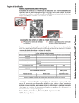
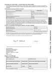
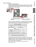
Drive serial number locations
a - Transmission serial number
b - Drive serial number decal and
plate
stamping
Refer to the engine operation and maintenance manual available from the engine
manufacturer for the location of the engine data tag, which contains the engine serial
number and model number.
Please record the following information:
Drive Serial Numbers
Zeus Drive Serial Number Transmission Serial Number
Port
Starboard
Engine Model and Horsepower
/
Engine Serial Number
Port
Starboard
Propeller Information
Propeller Part Number
Front
‑
Rear
‑
Boat Hull Identification Number (HIN)
Pitch
Cummins QSB and QSC Zeus Drive Models
b
Purchase Date
/
Boat Manufacturer
Boat Model
Boat Length
Exhaust Gas Emissions Certificate Number (Europe Only)
/
The description and specifications contained herein were in effect at the time this
guide was approved for printing. CMD, whose policies are based on continuous
improvement, reserves the right to discontinue models at any time or to change
specifications or designs without notice and without incurring obligation.
Mercury Marine, Fond du Lac, Wisconsin, U.S.A. Printed in U.S.A.
© 2007 Mercury Marine
.
©2007, Mercury Marine
Mercury, Mercury Marine, MerCruiser, Mercury MerCruiser, Mercury Racing, Mercury
Precision Parts, Mercury Propellers, Mariner, Quicksilver, #1 On The Water, Alpha, Bravo,
Pro Max, OptiMax, Sport‑Jet, K‑Planes, MerCathode, RideGuide, SmartCraft, Zero Effort,
M with Waves logo, Mercury with Waves logo, and SmartCraft logo are all registered
trademarks of Brunswick Corporation. Mercury Product Protection logo is a registered
service mark of Brunswick Corporation.
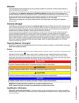
Welcome
You have selected one of the finest marine power packages available. It incorporates
numerous design features to ensure operating ease and durability.
With proper care and maintenance, you will thoroughly enjoy using this product for many
boating seasons. To ensure maximum performance and carefree use, we ask that you
thoroughly read this manual, which contains specific instructions for using and maintaining
your product. We suggest that this manual remain with the product for reference whenever
you are on the water.
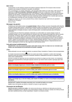
Thank you for purchasing one of our Cummins MerCruiser Diesel products. We sincerely
hope your boating will be pleasant.
Cummins MerCruiser Diesel
Warranty Message
The product you have purchased comes with a limited warranty from Cummins
MerCruiser Diesel; the terms of the warranty are set forth in the Warranty Sections of this
manual. The warranty statement contains a description of what is covered, what is not
covered, the duration of coverage, how to best obtain warranty coverage, important
disclaimers and limitations of damages, and other related information. Please review
this important information.
Read This Manual Thoroughly
IMPORTANT: If you do not understand any portion of this manual, contact your dealer for
a demonstration of the actual starting and operating procedures.
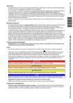
Notice
Throughout this publication, and on your power package, dangers, warnings, cautions, and
notices, accompanied by the International Hazard Symbol ! , may be used to alert the
installer and user to special instructions concerning a particular service or operation that
may be hazardous if performed incorrectly or carelessly. These safety alerts follow ANSI
standard Z535.6‑2006 for product safety information in product manuals, instructions, and
other collateral materials. Observe them carefully.
These Safety Alerts alone cannot eliminate the hazards that they signal. Strict compliance
with these special instructions while performing the service, plus common sense operation,
are major accident prevention measures.
! DANGER
Indicates a hazardous situation which, if not avoided, will result in death or serious injury.
! WARNING
Indicates a hazardous situation which, if not avoided, could result in death or serious
injury.
! CAUTION
Indicates a hazardous situation which, if not avoided, could result in minor or moderate
injury.
NOTICE
Indicates a situation which, if not avoided, could result in engine or major component
failure.
IMPORTANT: Identifies information essential to the successful completion of the task.
NOTE: Indicates information that helps in the understanding of a particular step or action.
! WARNING
The operator (driver) is responsible for the correct and safe operation of the boat, the
equipment aboard and the safety of all occupants aboard. We strongly recommend that
the operator read this Operation, Maintenance and Warranty Manual and thoroughly
understand the operational instructions for the power package and all related accessories
before the boat is used.
! WARNING
The engine exhaust from this product contains chemicals known to the state of California
to cause cancer, birth defects or other reproductive harm.
TABLE OF CONTENTS
Section 1 - Limited Warranty
Warranty Information...............................................2
Warranty Registration—United States and
Canada.............................................................2
Warranty Registration—Outside the United
States and Canada........................................... 2
Limited Warranty Coverage.............................. 3
Zeus Drive Limited Warranty Against Corrosion
(Worldwide)......................................................7
Emission Warranty...........................................8
Transfer Of Warranty........................................ 8
Section 2 - Getting to Know Your Power Package
General Information...............................................12
Models Covered.............................................12
Drive Serial Number and Decal Placement....12
Features and Controls...........................................12
Emergency Stop (E‑Stop) Switch...................12
Instrumentation...............................................13
VesselView...................................................13
Digital Gauges (If Equipped)........................13
Analog Gauges (If Equipped).......................14
Electronic Helm Steering................................15
Dual‑Handle Electronic Remote Control (ERC)
with DTS Trackpad Features and Operation. .15
Operation.....................................................15
Basic Joystick Operation................................17
Electrical System Overload Protection...........17
Vessel Interface Panel (VIP) Overload
Protection.....................................................18
Overload Protection for Other Circuits.........18
Zeus Drive Alignment.....................................18
Section 3 - On The Water
Safe Boating Suggestions.....................................20
Be Alert To Carbon Monoxide Poisoning.......21
Good Ventilation...........................................21
Poor Ventilation ...........................................22
Basic Boat Operation.............................................22
Freezing Temperature and Cold Weather
Operation........................................................22
Drain Plug and Bilge Pump............................23
Protecting People in the Water.......................23
While the Boat is Moving..............................23
While the Boat is Stationary.........................23
Wave and Wake Jumping..............................24
Impact with Underwater Hazards...................24
Zeus Drive Impact Protection.........................25
Conditions Affecting Boat Operation.....................25
Weight Distribution (Passengers and Gear)
Inside the Boat...............................................25
Bottom Of Boat...............................................26
Cavitation.......................................................26
Ventilation.......................................................26
Propeller Selection.........................................26
Getting Started......................................................27
Break‑In Period (New or With Replacement
Gears)............................................................27
CMD-4082031 / 90-866938070 AUGUST 2007
Starting and Stopping the Engines.................27
Normal Starting............................................27
Normal Stopping..........................................28
Starting the Engines—Manual Override.......28
Stopping the Engines—Manual Override.....30
Traditional Maneuvering with Steering and
Thrust.............................................................30
To Maneuver the Boat in Forward................31
To Steer the Boat in Tight Turns at Low
Speeds.........................................................31
To Spin the Boat on its Axis at Low Speeds 31
Maneuvering with the Joystick.......................31
Trim Tab Override..........................................35
Manual Adjustment......................................35
Trim Tab Override Use.................................36
Getting on Plane..........................................36
Smoothing the Ride......................................36
Correcting a List...........................................36
Low Speed Trim...........................................36
Page i
Special Digital Throttle and Shift (DTS)
Features........................................................37
Troll and Throttle Response........................ 38
Dock............................................................39
Throttle Only............................................... 39
1 (One) Lever..............................................40
Sync............................................................40
Cruise Control............................................... 41
Precision Pilot Track Pad Features...............41
General Information.................................... 41
Standby.......................................................42
Standby and Active Lights.......................... 43
Power Icon..................................................43
Skyhook...................................................... 44
Skyhook Screen Notes.............................45
Engaging Skyhook....................................46
Disengaging Skyhook...............................46
Turn Buttons............................................... 47
Auto Heading............................................48
Disengage Auto Heading..........................49
To Resume to a Heading ...........................50
Track Waypoint...........................................51
Engaging Track Waypoint Mode.................52
Disengaging Track Waypoint Mode............53
Turn Button or Joystick in Track Mode....... 53
Auto Heading Button in Track Mode ..........53
Acknowledging a Turn During a Waypoint
Arrival..........................................................54
Waypoint Sequence....................................55
Waypoint Acknowledge .............................. 56
Response Button........................................ 58
Changing VesselView Mode Display
Times.......................................................... 58
End of First Season Checkup....................... 58
Contingent Operations......................................... 59
Backup Steering System...............................59
Port Engine Only Operation.......................... 59
Gear Engagement—Emergency Procedure. 59
Section 4 - Specifications
Drive Gear Lubricant............................................ 62
Transmission........................................................62
Steering Actuator and Trim Fluid.......................... 62
Approved Paints...................................................62
Approved Lubricants............................................ 62
Section 5 - Maintenance
Product Responsibilities.......................................66
Owner and Operator Responsibilities........... 66
Dealer Responsibilities..................................66
Do‑It‑Yourself Maintenance Suggestions...... 66
Inspection......................................................67
Drive Cover.......................................................... 67
Removing the Drive Cover............................67
Cleaning and Inspecting the Drive Cover...... 68
Installing the Drive Cover..............................68
Maintenance Schedules.......................................69
Application.....................................................69
Routine Maintenance.................................... 69
Scheduled Maintenance................................ 69
Maintenance Log........................................... 70
Drive Gear Lube...................................................72
Checking....................................................... 72
Filling.............................................................73
Changing.......................................................74
With the Boat in the Water..........................74
With the Boat Out of the Water...................77
Steering Actuator and Trim Fluid.......................... 79
Checking....................................................... 79
Filling.............................................................80
Page ii
Changing.......................................................80
Transmission Fluid............................................... 81
Checking....................................................... 81
Filling.............................................................82
Changing.......................................................83
Seawater Strainer.................................................86
Battery..................................................................87
Gauges.................................................................87
Checking Gauges.......................................... 87
Cleaning Gauges.......................................... 87
Electrical System..................................................87
Cooling System and Exhaust System.................. 87
Lubrication............................................................88
Driveshaft Slip‑Joint ..................................... 88
Seacock—Seawater Return (Overboard)..... 89
Propeller Shaft.............................................. 90
Corrosion Protection.............................................90
Anodes and MerCathode System ................ 90
Reference Electrode Wire of the MerCathode
System.......................................................... 91
MerCathode Anode.......................................92
Checking.....................................................92
Replacing....................................................92
CMD-4082031 / 90-866938070 AUGUST 2007
MerCathode System Testing..........................92
Trim Tab Anodes............................................93
Checking......................................................93
Replacing.....................................................93
Continuity Circuits..........................................93
Inhibiting Corrosion........................................94
Painting the Boat............................................94
Propellers..............................................................95
Propeller Removal..........................................95
Propeller Repair.............................................97
Propeller Installation.......................................97
Section 6 - Storage
Cold Weather (Freezing Temperature) Storage and
Seasonal Storage................................................102
Storage Descriptions....................................102
Preparing the Power Package for Storage..........102
Drive Storage...............................................102
Engine Storage.............................................103
Battery Storage....................................................103
Recommissioning................................................103
Engine..........................................................103
Drive.............................................................103
Power Package............................................103
Section 7 - Troubleshooting
Diagnosing Electronically Controlled Fuel System
Problems.............................................................106
Electrical Connections.........................................106
Troubleshooting Charts.......................................106
Troubleshooting Engine Related Problems. .106
Check VesselView First................................106
Poor Performance........................................107
Joystick.........................................................107
Electronic Remote Controls..........................107
Steering System...........................................108
Trim Tabs.....................................................109
Boat Response Changes.............................109
Battery Will Not Charge................................109
Gauges and Instrumentation........................110
Section 8 - Customer Assistance Information
Owner Service Assistance...................................112
Local Repair Service.......................................112
Service Away From Home..............................112
Stolen Power Package...................................112
Attention Required After Submersion.............112
Replacement Service Parts............................112
Parts and Accessories Inquiries.....................113
Resolving a Problem.......................................113
Customer Service Literature................................113
English Language...........................................113
Other Languages............................................114
Andre sprog....................................................114
Andere talen...................................................114
CMD-4082031 / 90-866938070 AUGUST 2007
Muut kielet......................................................114
Autres langues................................................114
Andere Sprachen............................................114
Altre lingue......................................................114
Andre språk....................................................114
Outros Idiomas...............................................114
Otros idiomas..................................................115
Andra språk....................................................115
Allej glþssej.....................................................115
Ordering Literature..............................................115
United States and Canada..............................115
Outside The United States and Canada.........115
Page iii
Page iv
CMD-4082031 / 90-866938070 AUGUST 2007
Section 1 - Limited Warranty
Section 1 - Limited Warranty
1
Table of Contents
Warranty Information............................................ 2
Warranty Registration—United States and
Canada............................................................2
Warranty Registration—Outside the United
States and Canada.........................................2
CMD-4082031 / 90-866938070 AUGUST 2007
Limited Warranty Coverage............................3
Zeus Drive Limited Warranty Against Corrosion
(Worldwide).....................................................7
Emission Warranty..........................................8
Transfer Of Warranty......................................8
Page 1
Section 1 - Limited Warranty
Warranty Information
Warranty Registration—United States and Canada
The CMD warranty registration center will coordinate warranty registration for both
CMD/Cummins and Mercury Marine products, only one Warranty Registration Form
is required to be filed for each engine/drive system.
1. To ensure that your warranty coverage begins promptly, your selling dealer should fill
out the Warranty Registration Card completely and mail it to the factory immediately
upon sale of the new product.
2. The Warranty Registration Card identifies the name and address of the original
purchaser, product model and serial number(s), date of sale, type of use and selling
dealer’s code, name, and address. The dealer also certifies that you are the original
purchaser and user of the product. A temporary Owner Warranty Registration Card will
be presented to you when you purchase the product.
3. Upon receipt of the Warranty Registration Card at the factory, you will be sent an owner
resource guide that includes your warranty registration confirmation. If you do not
receive your owner resource guide within 60 days from date of new product sale, please
contact your selling dealer.
4. Because of your selling dealer’s ongoing interest in your satisfaction, the product
should be returned to him for warranty service.
5. The product warranty is not effective until the product is registered at the factory.
NOTE: Registration lists must be maintained by the factory and dealer on marine products
sold in the United States in the event that a safety recall notification under the Federal Boat
Safety Act is required.
6. You may change your registration address at any time, including at time of warranty
claim, by calling CMD or sending a letter or fax with your name, old address, new
address, and engine serial number to CMD's warranty registration department. Your
dealer can also process this change of information.
United States customers or dealers may contact:
Cummins MerCruiser Diesel LLC, Inc.
Attn: Warranty Registration Department
4500 Leeds Avenue - Suite 301
Charleston, South Carolina 29405
1-800-668-0407
Fax Fax 843-745-1616
Warranty Registration—Outside the United States and Canada
1. It is important that your selling dealer fills out the Warranty Registration Card completely
and mails it to the Cummins MerCruiser Diesel Distributor or Cummins MerCruiser
Diesel Authorized Dealer responsible for administering the warranty registration and
claim program for your area.
2. The Warranty Registration Card identifies your name and address, product model and
serial numbers, date of sale, type of use and the selling distributor's and dealer's code
number, name and address. The distributor or dealer also certifies that you are the
original purchaser and user of the product.
Page 2
CMD-4082031 / 90-866938070 AUGUST 2007
Section 1 - Limited Warranty
3. A copy of the Warranty Registration Card, designated as the Purchaser's Copy, MUST
be given to you immediately after the card has been completely filled out by the selling
distributor or dealer. This card represents your factory registration identification, and
should be retained by you for future use when required. Should you ever require
warranty service on this product, your dealer may ask you for the Warranty Registration
Card to verify date of purchase and to use the information on the card to prepare the
warranty claim forms.
4. In some countries, the Cummins MerCruiser Diesel Distributor or Cummins MerCruiser
Diesel Authorized Dealer will receive the Factory Copy of the Warranty Registration
Card from your distributor or dealer. If you receive a plastic Warranty Registration Card,
you may discard the Purchaser's Copy that you received from the distributor or dealer
when you purchased the product. Ask your distributor or dealer if this plastic card
program applies to you. Center will issue you a permanent (plastic) Warranty
Registration Card within 30 days after
5. For further information concerning the Warranty Registration Card and its relationship
to Warranty Claim processing, refer to the International Warranty. See Table of
Contents. IMPORTANT: Registration lists must be maintained by the factory and dealer
in some countries by law. It is our desire to have ALL products registered at the factory
should it ever be necessary to contact you. Make sure your Cummins MerCruiser Diesel
Distributor or Cummins MerCruiser Diesel Authorized Dealer fills out the warranty
registration card immediately and sends the factory copy to the Marine Power
International Service Center for your area.
Limited Warranty Coverage
Engines and Drive Systems Included in this Coverage
Marine Propulsion
Zeus 3500
Zeus 3800
Products Warranted
This limited warranty applies to new Engines and Drive Systems sold by Cummins MerCruiser Diesel LLC. Inc.,
herein after "CMD", that are branded as Cummins MerCruiser Diesel products and used in Marine applications
anywhere in the world where CMD approved service is available1. and delivered to the first user on or after
September 1, 2007. This limited warranty excludes all Engines branded and sold as Cummins Marine Diesel
products. The ’Product’ consists of a new CMD Engine and Drive System, as well as accessories, which are
approved and supplied by CMD and Cummins, and which are either installed by CMD or a CMD authorized
distributor. These Products have the following designation:
High Output Rating
Intended for use in variable load applications where full power is limited to one hour out of every eight hours of
operation. Reduced power must be at or below 200 RPM of the maximum RPM. This power rating is for pleasure
craft applications that operate less than 500 hours per year.
Base Engine and Drive Limited Warranty
This limited warranty covers any failures of the Product, under normal use and service, which result from a
defect in CMD material or factory workmanship (Warrantable Failure) Underwater impact damage is not a
warrantable failure. Coverage begins with the retail sale of the Engine and Drive by CMD and continues for the
Duration stated in the following table. The Duration commences on either the date of delivery of the Product to
the first user, or the date the unit is first leased, rented or loaned, or when the Product has been operated for
125 hours, whichever occurs first. Commercial use of this product voids the warranty. Commercial use is defined
as any work or employment related use of the product, or any use of the product which generates income, for
any part of the warranty period, even if the product is only occasionally used for such purposes.
1. Locations in the United States and Canada are listed in the Cummins United States and Canada Sales and Service Directory;
other locations are listed in the Cummins International Sales and Service Directory.
CMD-4082031 / 90-866938070 AUGUST 2007
Page 3
Section 1 - Limited Warranty
Two Year Limited Warranty—Limited Warranty Coverage
Coverage Duration
(whichever occurs
first)
Repair Charge Paid by CMD
Coverage Category
Months
Hours
Parts
Labor
Removal and Installation
Labor
Travel
Base Engine Warranty
24
1000
Yes
Yes
Yes
Yes
Extended Major Components
72
3000
Yes
Yes
Yes
Yes
Extended Major Components Limited Warranty
The Extended Major Components Limited Warranty provision is concurrent with the Base Engine and Drive
Limited Warranty and continues beyond the expiration of the Base Engine and Drive Limited Warranty for an
additional four years or 2000 hours whichever occurs first. The Extended Major Components Limited Warranty
covers Warrantable Failures of the following Engine and Drive parts or castings (Covered parts):
Engine:
Engine Cylinder Block and Head Casting
Engine Camshaft and Crankshaft Forging
Engine Connecting Rod Forging
Engine Gear Train Gears:
—Crankshaft Gear
—Camshaft and Camshaft Idler Gear
—Accessory Drive Gear
—Fuel Pump Gear
Engine Gear Cover Casting
Flywheel Housing Casting
Bushing and bearing failures are NOT covered.
Drive:
Marine Gear Housing
Marine Gear Drop Box Housing
Steering Actuator Housing Casting
Drive Mid‑section Casting
Lower Gear Housing Casting – (Underwater Impact Damage Excluded)
Trim Tab Casting – (Underwater Impact Damage Excluded)
Bearing Carrier Casting – (Underwater Impact Damage Excluded)
Drive Shaft – (Less U‑joints)
Intermediate Shaft – (Underwater Impact Damage Excluded)
Clamp Rings
Steering and Trim Oil Tank
Skeg – (Underwater Impact Damage Excluded)
Consumer Products
Page 4
CMD-4082031 / 90-866938070 AUGUST 2007
Section 1 - Limited Warranty
The warranty on Consumer Products in the United States is a limited warranty. CMD IS NOT RESPONSIBLE
FOR INCIDENTAL OR CONSEQUENTIAL DAMAGES. Any implied warranties applicable to Consumer
Products terminate concurrently with the expiration of the express warranties applicable to the Product. In the
United States, some states do not allow the exclusion of incidental or consequential damages, or limitations on
how long an implied warranty lasts, so the limitations or exclusions herein may not apply to you.
These warranties are made to all Owners in the chain of distribution and Coverage continues to all
subsequent Owners until the end of the periods of Coverage.
CMD Responsibilities
During the Base Engine Limited Warranty
CMD will pay for all parts and labor needed to repair the damage to the Product resulting from a Warrantable
Failure when performed during normal business hours. All labor costs will be paid in accordance with Cummins
and Mercury Marine's published Standard Repair Time guidelines. When it is necessary for mechanics to make
on‑site warranty repairs, CMD will pay reasonable travel expenses, including meals, mileage and lodging, for
mechanics to travel to and from the repair dock.
CMD will pay for the lubricating oil, antifreeze, filter elements, and other maintenance items that are not reusable
due to the Warrantable Failure.
CMD will pay for reasonable labor costs for Engine and Drive System removal and reinstallation when necessary
to repair a Warrantable Failure.
During the Extended Major Components Limited Warranty
CMD will pay for parts and labor for the repair or, at its option, the replacement of the defective covered part
and any covered part damaged by a warrantable failure of the defective covered part.
Owner Responsibilities
During Both the Base Engine and Drive System and the Extended Major Components Limited
Warranties
Owner is responsible for the cost of lubricating oil, antifreeze, filter elements, and other maintenance items
replaced during warranty repairs unless such items are not reusable due to the Warrantable Failure.
During the Extended Major Components Limited Warranties
Owner is responsible for the cost of all parts and labor required for the repair except for the defective Covered
Part and any Covered Part damaged by a Warrantable Failure of the defective Covered Part.
Owner is responsible for the operation and maintenance of the Product as specified in the applicable Cummins,
MerCruiser, or CMD Operation and Maintenance Manual. Owner is also responsible for providing proof that all
recommended maintenance has been performed.
Exceeding the operational parameters of the HO rating will void this warranty. The owner of the boat is ultimately
responsible for ensuring the engine and drive system is properly operated and maintained. The warranty will
be void on any Engines and Drives that are misapplied, not maintained properly or misused.
Before the expiration of the applicable warranty, Owner must notify a CMD distributor, authorized dealer, or
other repair location approved by CMD of any Warrantable Failure and make the Engine and Drive System
available for repair by such facility. Locations in the United States and Canada are listed in the Cummins U.S.
and Canada Sales and Service Directory; other locations are listed in the Cummins International Sales and
Service Directory.
In the event of any Product failure, Owner is responsible for the cost of towing the boat to the repair dock and
for all associated docking, storage, and harbor charges.
Owner is responsible for communication expenses, meals, lodging, and similar costs incurred as a result of a
Warrantable Failure.
Owner is responsible for maintaining the Engine hour meter in good working order at all times and to ensure
that the hour meter accurately reflects the total hours of operation of the Product.
Owner is responsible for the costs to investigate complaints, unless the problem is caused by a defect in CMD
material or factory workmanship.
Owner is responsible for non‑Engine and non‑Drive System repairs, "downtime" expenses, cargo damage,
fines, all applicable taxes, all business costs, and other losses resulting from a Warrantable Failure.
Limitations
CMD-4082031 / 90-866938070 AUGUST 2007
Page 5
Section 1 - Limited Warranty
CMD is not responsible for failures or damage resulting from what CMD determines to be abuse or neglect,
including, but not limited to: operation without adequate coolants or lubricants; over‑fueling; over‑speed; lack
of system maintenance to the engine and drive: improper storage, starting, warm‑up, run‑in or shutdown
practices, corrosion of Engine or Drive due to lack of maintenance; unauthorized modifications to the Engine
or Drive. CMD is also not responsible for failures caused by incorrect oil or fuel or by water, dirt or other
contaminants in the fuel or oil.
CMD is not responsible for failure resulting from:
1.
Use or application of the Product inconsistent with its rating designation set forth above.
2.
Incorrect installation.
3.
Engines that do not reach rated RPM because of issues unrelated to the engine (for example, overloading
the vessel, selecting an engine with insufficient horsepower for the vessel, improper gear and/or propeller
selection, inadequate hull maintenance, etc.).
4.
Use of improper propellers.
5. The lack of completing published maintenance procedures.
Before a claim for excessive oil consumption will be considered, Owner must submit adequate documentation
to show that oil consumption exceeds CMD published standards.
CMD does not warrant accessories or parts that are not supplied by Cummins/Mercury Marine Factory.
CMD is not responsible for failures of maintenance Components supplied by Cummins/Mercury Marine beyond
90 days After the coverage duration start date. Maintenance Components include, but are not limited to: sea
water pump impellers; zinc plugs; oil filters; fuel filters; air filters; water filters; and fuel/water separator filters.
Except for the accessories noted previously, CMD does not warrant accessories which bear the name of another
company.
Parts used in warranty repairs may be new Cummins/Mercury Marine parts, or Cummins / Mercury
Marine‑approved rebuilt or repaired parts. CMD is Not responsible for failures resulting from the use of Parts
not supplied by Cummins/Mercury Marine.
A new Cummins/Mercury Marine part or Cummins / Mercury Marine‑approved rebuilt part used to replace a
Warranted Part assumes the identity of the Warranted Part it replaced and is entitled to the remaining coverage
hereunder.
CMD DOES NOT COVER WEAR OR WEAROUT OF COVERED PARTS.
CMD IS NOT RESPONSIBLE FOR INCIDENTAL OR CONSEQUENTIAL DAMAGES.
THESE WARRANTIES SET FORTH HEREIN ARE THE SOLE WARRANTIES MADE BY CMD IN REGARD
TO THESE ENGINES. CMD MAKES NO OTHER WARRANTIES, EXPRESS OR IMPLIED, OR OF
MERCHANTABILITY OR FITNESS FOR A PARTICULAR PURPOSE.
In the United States2. and Canada, this warranty gives you specific legal rights, and you may also have other
rights which vary from state to state.
Outside the United States3.and Canada, in case of consumer sales, in some countries the Owner has statutory
rights which cannot be affected or limited by the terms of this warranty.
Nothing in this warranty excludes or restricts any contractual rights the Owner may have against third parties.
2. United States includes American Samoa, the Commonwealth of Northern Mariana Island, Guam, Puerto Rico and the U.S. Virgin
Islands.
3. United States includes American Samoa, the Commonwealth of Northern Mariana Island, Guam, Puerto Rico and the U.S. Virgin
Islands.
Page 6
CMD-4082031 / 90-866938070 AUGUST 2007
Section 1 - Limited Warranty
Zeus Drive Limited Warranty Against Corrosion (Worldwide)
What Is Covered
Cummins MerCruiser Diesel warrants the Zeus Drive (Product) will not be rendered inoperative as a direct
result of corrosion for the period of time described below.
Duration of Coverage
This limited corrosion warranty provides coverage for three (3) years / 1500 Hours from either the date the
product is first sold, or the date on which the product is first put into service, whichever occurs first. The
repair and replacement of parts, or the performance of service under this warranty does not extend the life
of this warranty beyond its original expiration date. Unexpired warranty coverage can be transferred to
subsequent purchaser upon proper reregistration of the product. Warranty coverage is terminated for used
product repossessed from a retail customer, purchased at auction, from a salvage yard, or from an insurance
company that obtained the product as a result of an insurance claim.
Conditions That Must Be Met to Obtain Warranty Coverage
Corrosion prevention devices specified in the Operation, Maintenance, and Warranty manual must be in use
on the boat, and routine maintenance outlined in the Operation, Maintenance, and Warranty manual must
be timely performed (including without limitation the replacement of sacrificial anodes, use of specified
lubricants, and touch‑up of nicks and scratches) in order to maintain warranty coverage. Cummins
MerCruiser Diesel reserves the right to make warranty coverage contingent upon proof of proper
maintenance.
What Cummins MerCruiser Diesel Will Do
Cummins MerCruiser Diesel and Mercury's sole and exclusive obligation under this warranty is limited to,
at our option, repairing a corroded part, replacing such part or parts with new or CMD / Mercury
Marine‑certified, remanufactured parts, or refunding the purchase price of the CMD / Mercury product. CMD /
Mercury reserves the right to improve or modify products from time to time without assuming an obligation
to modify products previously manufactured.
How to Obtain Warranty Coverage
The customer must provide Cummins MerCruiser Diesel with reasonable access to the product for warranty
service and a reasonable opportunity to repair the product. Cummins MerCruiser Diesel dealer will arrange
for the inspection and any covered repair. If the service provided is not covered by this warranty, purchaser
shall pay for all related labor and material, and any other expenses associated with that service. Purchaser
shall not, unless requested by Cummins MerCruiser Diesel, ship the product or parts of the product directly
to Cummins MerCruiser Diesel. Proof of registered ownership must be presented to the dealer at the time
warranty service is requested in order to obtain coverage.
What Is Not Covered
This limited warranty does not cover electrical system corrosion; corrosion resulting from damage; corrosion
that causes purely cosmetic damage; abuse or improper service; corrosion to accessories, instruments, or
steering systems; damage due to marine growth; replacement parts (parts purchased by the customer);
products used in a commercial application. Commercial use is defined as any work‑related or
employment‑related use of the product, or any use of the product that generates income, for any part of
warranty period, even if the product is only occasionally used for such purposes.
CMD-4082031 / 90-866938070 AUGUST 2007
Page 7
Section 1 - Limited Warranty
Emission Warranty
Product Warranted
This Emission Warranty applies to new Engines certified to United States EPA 40 CFR 94 sold by CMD that
are installed in vessels flagged or registered in the Unites States.1.2.
Coverage
CMD warrants to the first user and each subsequent purchaser that the Engine is designed, built, and
equipped so as to conform at the time of sale by CMD with all U.S. Federal emission regulations applicable
at the time of manufacture and that it is free from defects in workmanship or material which would cause it
not to meet these regulations within the longer of the following periods:
1.
Five years or 500 hours of operation, whichever occurs first, The Emissions Warranty starts from the
date of delivery of the Engine to the first user, or the date the unit is first leased, rented, or loaned, or
when the Engine has been operated for 50 hours, whichever occurs first, or
2.
The Base Engine Warranty.
Limitations
The owner may elect to have maintenance, replacement, or repair of the emission control parts performed
by a facility other than a CMD distributor, an authorized dealer or a repair location approved by CMD, and
may elect to use parts other than new genuine Cummins/Mercury Marine or Cummins / Mercury
Marine‑approved rebuilt parts and assemblies for such maintenance, replacement or repair; however, the
cost of such service or parts and subsequent failures resulting from such service or parts will not be covered
under this emission control system warranty.
Failures, except those resulting from a defect in materials, or factory workmanship, are not covered by the
WARRANTY.
CMD IS NOT RESPONSIBLE FOR INCIDENTAL OR CONSEQUENTIAL DAMAGES.
In the United States3. and Canada, this warranty gives you specific legal rights, and you may also have other
rights which vary from state to state.
Outside the United States4. and Canada, in case of consumer sales, in some countries the Owner has
statutory rights which cannot be affected or limited by the terms of this warranty.
Nothing in this warranty excludes or restricts any contractual rights the Owner may have against third parties
Transfer Of Warranty
The limited warranty is transferable to a subsequent purchaser, but only for the remainder
of the unused portion of the limited warranty. This will not apply to products used for
commercial applications.
To transfer the warranty to the subsequent owner, send or fax a copy of the bill of sale or
purchase agreement, new owner's name, address and engine serial number to CMD's
warranty registration department.
In the United States mail to:
Cummins MerCruiser Diesel LLC, Inc.
Attn: Warranty Registration Department
4500 Leeds Avenue - Suite 301
Charleston, South Carolina 29405
1-800-668-0407
Fax Fax 843-745-1616
Upon processing the transfer of warranty, CMD will send registration verification to the new
owner of the product by mail. There is no charge for this service.
1. Locations in the United States and Canada are listed in the Cummins United States and Canada Sales and Service Directory;
other locations are listed in the Cummins International Sales and Service Directory.
2. United States includes American Samoa, the Commonwealth of Northern Mariana Islands, Guam, Puerto Rico, and the U.S. Virgin
Islands.
3. United States includes American Samoa, the Commonwealth of Northern Mariana Islands, Guam, Puerto Rico, and the U.S. Virgin
Islands.
4. United States includes American Samoa, the Commonwealth of Northern Mariana Islands, Guam, Puerto Rico, and the U.S. Virgin
Islands.
Page 8
CMD-4082031 / 90-866938070 AUGUST 2007
Section 1 - Limited Warranty
For products purchased outside the United States and Canada, contact the Cummins
MerCruiser Diesel Distributor or Cummins MerCruiser Diesel distributor in your country.
CMD-4082031 / 90-866938070 AUGUST 2007
Page 9
Section 1 - Limited Warranty
Notes:
Page 10
CMD-4082031 / 90-866938070 AUGUST 2007
Section 2 - Getting to Know Your Power Package
Section 2 - Getting to Know Your Power Package
Table of Contents
General Information............................................ 12
Models Covered............................................12
Drive Serial Number and Decal Placement
......................................................................12
Features and Controls........................................ 12
Emergency Stop (E-Stop) Switch.................. 12
Instrumentation.............................................13
VesselView ............................................. 13
Digital Gauges (If Equipped) .................. 13
Analog Gauges (If Equipped) ................. 14
Electronic Helm Steering...............................15
CMD-4082031 / 90-866938070 AUGUST 2007
Dual-Handle Electronic Remote Control (ERC)
with DTS Trackpad Features and Operation
......................................................................15
Operation ............................................... 15
Basic Joystick Operation...............................17
Electrical System Overload Protection..........17
Vessel Interface Panel (VIP) Overload
Protection ............................................... 18
Overload Protection for Other Circuits
............................................................... 18
Zeus Drive Alignment....................................18
2
Page 11
Section 2 - Getting to Know Your Power Package
General Information
Models Covered
Models Covered
Engine Model and Rating
Serial Number Or Year
QSB5.9–330 (High Output)
QSB5.9–355 Intermittent
Zeus 3500
QSB5.9–380 (HO)
Information not available at time of printing
QSB5.9–425 (HO)
QSB5.9–480 (HO)
Zeus 3800
QSC8.3–550 (HO)
Information not available at time of printing
Drive Serial Number and Decal Placement
Serial numbers are the manufacturer's key to numerous engineering details that apply to
your drive.
a
b
27495
Drive serial number locations
a - Transmission serial number plate
b - Drive serial number decal and stamping
Refer to the engine operation and maintenance manual, available from the engine
manufacturer, for the location of the engine data tag that contains the engine serial number
and model number.
Features and Controls
Emergency Stop (E‑Stop) Switch
The emergency stop (E‑stop) switch turns off the engines in an emergency situation, such
as a person overboard or tangled propeller. When activated, the E‑stop switch interrupts
the power supply to the main power relay, including power to the gauges, steering, and
accessories.
Activation of the E‑stop switch stops the engines immediately, but the boat continues to
coast for some distance depending upon the velocity and degree of any turn at shutdown.
However, the boat does not complete a full circle. While the boat is coasting, it can cause
injury to anyone in the boat's path as seriously as the boat would when under power.
We recommend instructing other occupants on proper starting and operating procedures
should they need to operate the engine in an emergency.
Page 12
CMD-4082031 / 90-866938070 AUGUST 2007
Section 2 - Getting to Know Your Power Package
Accidental or unintended activation of the switch during normal operation is also possible,
which can cause any or all of the following potentially hazardous situations:
• Occupants can be thrown forward due to unexpected loss of forward motion, a
particular concern for passengers in the front of the boat who could be ejected over the
bow and possibly struck by the propulsion or steering components.
• Operator can lose power and directional control in heavy seas, strong current, or high
winds.
• Operator can lose control when docking.
Instrumentation
VESSELVIEW
VesselView is the primary information source for the Zeus drive, all engine information,
fault codes, tank levels, boat direction, and calibrations. Refer to the VesselView Operators
Manual for more information.
27198
VesselView
DIGITAL GAUGES (IF EQUIPPED)
The Cummins MerCruiser Diesel SmartCraft instrument package augments the
information provided by VesselView. A few of the functions the instrument package can
display are:
• Engine RPM
• Boat speed
• Coolant temperature
• Oil pressure
• Battery voltage
• Fuel consumption
CMD-4082031 / 90-866938070 AUGUST 2007
Page 13
Section 2 - Getting to Know Your Power Package
•
Engine operating hours
a
b
c
24575
Typical SmartCraft gauges
a - Tachometer
b - Speedometer
c - LCD System View display
The SmartCraft instrument package also aids in identifying the fault codes associated with
the sounding of the engine audio warning system. The SmartCraft instrument package
displays critical engine alarm data and other potential problem areas on its LCD display.
Refer to the manual provided with your gauge package for basic operation information on
the SmartCraft Instrument package and for details on the warning functions monitored by
the system.
ANALOG GAUGES (IF EQUIPPED)
Other instrumentation packages have gauges that augment the information provided by
VesselView. The owner and operator should be familiar with all the instruments and their
functions on the boat. Because of the large variety of instrumentation and manufacturers,
have your boat dealer explain the gauges and normal readings that appear on your boat.
The following types of gauges may be included with your power package.
60
50
80
70
60
50
40
30
40
30
20
10
90
3
100
110
70
6
1
KPH
MPH
80
f
7
0
X 1000
RPM
8
b
4
4
FUEL
Page 14
5
120
a
0
4
2
4
H
L
OIL
c
10
16
C
H
BATT
TEMP
d
e
0 0 0 0 0
CRUISELOG
g
h
i
17352
CMD-4082031 / 90-866938070 AUGUST 2007
Section 2 - Getting to Know Your Power Package
Item
Gauge
Function
a
Speedometer
Indicates boat speed.
b
Tachometer
Indicates engine RPM.
c
Oil pressure gauge
Indicates engine oil pressure.
d
Voltmeter
Indicates battery voltage.
e
Water temperature gauge
Indicates engine operating temperature.
f
Fuel gauge
Indicates quantity of fuel in tank.
g
Hour meter
Records engine operating time.
h
Bilge blower switch
Operates bilge blower.
i
Ignition switch
Allows operator to start and stop engine.
Electronic Helm Steering
The Electronic Helm Steering is a true drive‑by‑wire system that controls the steering
through electronic signals. The feel of the steering is created by computer‑designated
resistance.
We recommend that you drive carefully until you have a chance to explore the Zeus
system's handling characteristics in an open area without obstructions or other boat traffic,
and you are familiar with the boat's responses. The steering is two turns lock‑to‑lock,
providing a fast steering response. The first few maneuvers at speed can be more abrupt
than expected. The number of turns lock to lock is adjustable by the distributor, if desired.
Dual‑Handle Electronic Remote Control (ERC) with DTS Trackpad Features and
Operation
OPERATION
The electronic remote control (ERC) handle controls the operation of shift and throttle. Push
the control handle forward from neutral to the first detent for forward gear. Continue pushing
the handle forward to increase speed. Pull the control handle from the forward position to
the neutral position to decrease speed and eventually stop. Pull the control handle back
from neutral to the first detent for reverse gear. Continue pulling the handle back to increase
speed in reverse.
CMD-4082031 / 90-866938070 AUGUST 2007
Page 15
Section 2 - Getting to Know Your Power Package
NOTE: In certain modes, gear position is determined by the position of the shift valves on
the transmission, not the position of the ERC levers. When using the joystick or while in
Skyhook, the computer moves the transmission in and out of gear even though the handles
are in neutral.
a
c
b
d
28086
abcd-
Neutral
Forward
Reverse
Bow of boat
The amount of force needed to move the ERC handles and to move the ERC handles
through the detents is adjustable to help prevent unwanted motion of the handle in rough
water.
To adjust ERC handle tension:
1. Remove the side cover.
2. Turn the screw clockwise to increase tension on the control handle and
counter‑clockwise to decrease tension.
3. Adjust to tension desired.
To adjust ERC handle detent tension:
1. Remove the side cover.
2. Turn the screw clockwise to increase tension on the control handle and
counter‑clockwise to decrease tension.
Page 16
CMD-4082031 / 90-866938070 AUGUST 2007
Section 2 - Getting to Know Your Power Package
3. Adjust to tension desired.
b
a
28087
Starboard side with side cover removed.
a - ERC handle tension screw
b - ERC handle detent tension screw
Basic Joystick Operation
The joystick offers precise, intuitive control of your boat during low speed and docking
maneuvers. The joystick translates the movement of the joystick into similar movement in
the boat. Engine speed is limited in this mode to prevent unacceptable boat dynamics
during maneuvers.
While operation with the joystick is easy to learn, we recommend that you drive the boat
in the traditional way until you can spend time in an open area free of obstructions and
traffic to learn how your boat responds to inputs. Further, we recommend that you
occasionally practice maneuvering in the traditional way to maintain your traditional drive
docking skills in case joystick control is temporarily not available.
Electrical System Overload Protection
If an electrical overload occurs, a fuse or a circuit breaker opens. Find and correct the cause
for the electrical overload before replacing the fuse or resetting the circuit breaker.
NOTE: In an emergency, when you must operate the engine and cannot locate or correct
the cause for the high current draw, turn off or disconnect all the accessories connected
to the engine and instrumentation wiring. Reset the circuit breaker. If the breaker remains
open, the electrical overload has not been eliminated. Contact your Cummins MerCruiser
Diesel Authorized Repair Facility to check the electrical system.
Circuit breakers and fuses provide protection for the electrical system as indicated. The
circuit breakers are located in various locations throughout the boat. Have your dealer show
you the location and identify the circuit that they protect.
After finding and correcting the cause of the overload, reset the circuit breaker by pressing
the reset button.
CMD-4082031 / 90-866938070 AUGUST 2007
Page 17
Section 2 - Getting to Know Your Power Package
VESSEL INTERFACE PANEL (VIP) OVERLOAD PROTECTION
The Vessel Interface Panel (VIP) contains six circuit breakers that help protect the
transmission harness, engine harness, vessel sensor harness, and helm harness.
a
d
b
e
c
f
26315
Port shown, starboard similar
Item
Circuit Breaker Rating
Protection
Location on VIP
a
15
Gear
Upper left
b
10
SIM/Vessel
Middle left
c
10
Helm
Lower left
d
5
Engine Diagnostics
Upper right
e
5
VIP Diagnostics
Middle right
f
25
Main
Lower right
The VIP itself is protected by a 30 amp in‑line fuse between the battery bank and the VIP.
The in‑line fuse is often located on the fuse panel. Ask your dealer for the location.
OVERLOAD PROTECTION FOR OTHER CIRCUITS
Other circuits may be protected by circuit breakers or fuses installed by the boat
manufacturer and can vary in appearance and location. Ask your dealer for the location
and operation instructions of all overload protection devices.
• Circuit breakers are used to protect the backup hydraulic system. The 30 amp breakers,
one for each drive, are installed by the boat manufacturer and may vary in appearance
and location. Ask your dealer for the location and operating instructions.
• The MerCathode system has a 20 amp in‑line fuse in the wire that connects from the
positive (+) battery terminal to the positive (+) terminal on the controller. If the fuse is
defective (open), the system will not operate, resulting in a loss of corrosion protection.
Have your dealer show you the location of and service procedures for the fuse.
Zeus Drive Alignment
The Zeus Drives are aligned by the boat manufacturer, and must not be adjusted by anyone
other than your Cummins MerCruiser Diesel Authorized Service and Repair Facility. The
Zeus drives automatically recalibrate to this setting at each startup. The drives do not need
to be re‑aligned under normal use.
Page 18
CMD-4082031 / 90-866938070 AUGUST 2007
Section 3 - On The Water
Section 3 - On The Water
Table of Contents
Safe Boating Suggestions.................................. 20
Be Alert To Carbon Monoxide Poisoning......21
Good Ventilation ..................................... 21
Poor Ventilation ..................................... 22
Basic Boat Operation.......................................... 22
Freezing Temperature and Cold Weather
Operation......................................................22
Drain Plug and Bilge Pump...........................23
Protecting People in the Water.....................23
While the Boat is Moving ........................ 23
While the Boat is Stationary ................... 23
Wave and Wake Jumping.............................24
Impact with Underwater Hazards..................24
Zeus Drive Impact Protection........................25
Conditions Affecting Boat Operation.................. 25
Weight Distribution (Passengers and Gear)
Inside the Boat..............................................25
Bottom Of Boat..............................................26
Cavitation......................................................26
Ventilation.....................................................26
Propeller Selection........................................26
Getting Started.................................................... 27
Break-In Period (New or With Replacement
Gears)...........................................................27
Starting and Stopping the Engines................27
Normal Starting ...................................... 27
Normal Stopping .................................... 28
Starting the Engines—Manual Override
............................................................... 28
Stopping the Engines—Manual Override
............................................................... 30
Traditional Maneuvering with Steering and
Thrust............................................................30
To Maneuver the Boat in Forward .......... 31
To Steer the Boat in Tight Turns at Low
Speeds ................................................... 31
To Spin the Boat on its Axis at Low Speeds
............................................................... 31
Maneuvering with the Joystick......................31
Trim Tab Override.........................................35
Manual Adjustment ................................ 35
Trim Tab Override Use ........................... 36
Getting on Plane .................................... 36
CMD-4082031 / 90-866938070 AUGUST 2007
Smoothing the Ride ................................ 36
Correcting a List ..................................... 36
Low Speed Trim ..................................... 36
Special Digital Throttle and Shift (DTS) Features
......................................................................37
Troll and Throttle Response ................... 38
Dock ....................................................... 39
Throttle Only ........................................... 39
1 (One) Lever ......................................... 40
Sync ....................................................... 40
Cruise Control...............................................41
Precision Pilot Track Pad Features...............41
General Information ............................... 41
Standby .................................................. 42
Standby and Active Lights ...................... 43
Power Icon ............................................. 43
Skyhook ................................................. 44
Skyhook Screen Notes ..................... 45
Engaging Skyhook ........................... 46
Disengaging Skyhook ....................... 46
Turn Buttons ........................................... 47
Auto Heading .................................... 48
Disengage Auto Heading ................. 49
To Resume to a Heading ...................... 50
Track Waypoint ...................................... 51
Engaging Track Waypoint Mode ............ 52
Disengaging Track Waypoint Mode ....... 53
Turn Button or Joystick in Track Mode
............................................................... 53
Auto Heading Button in Track Mode ..... 53
Acknowledging a Turn During a Waypoint
Arrival ..................................................... 54
Waypoint Sequence ............................... 55
Waypoint Acknowledge ......................... 56
Response Button .................................... 58
Changing VesselView Mode Display Times
............................................................... 58
End of First Season Checkup.......................58
Contingent Operations........................................ 59
Backup Steering System...............................59
Port Engine Only Operation..........................59
Gear Engagement—Emergency Procedure
......................................................................59
3
Page 19
Section 3 - On The Water
Safe Boating Suggestions
In order to safely enjoy the waterways, familiarize yourself with local and all other
governmental boating regulations and restrictions, and also consider the following
suggestions.
• Know and obey all nautical rules and laws of the waterways.
Cummins MerCruiser Diesel strongly recommends that all powerboat operators complete
a boating safety course. Courses are offered in the U.S.A. by the U.S. Coast Guard
Auxiliary, the Power Squadron, the Red Cross, and your state or provincial boating law
enforcement agency. Inquiries may be made to the Boating Hotline at 1‑800‑368‑5647 or
the Boat U.S. Foundation at 1‑800‑336‑BOAT.
• Perform safety checks and required maintenance. Follow a regular schedule and
ensure that all repairs are properly made.
• Check safety equipment on board. Here are some suggestions of the types of safety
equipment to carry when boating:
Approved fire extinguishers
Paddle or oar
Signal devices: flashlight, rockets or flares, flag, and whistle or horn
Transistor radio
Tools necessary for minor repairs
First aid kit and instructions
Anchor and extra anchor line
Waterproof storage containers
Manual bilge pump and extra drain plugs
Spare operating equipment, batteries, bulbs, and fuses
Drinking water
Compass and map or chart of the area
•
•
•
•
•
•
Page 20
Watch for signs of weather change and avoid foul weather and rough-sea
boating.
Tell someone where you are going and when you expect to return.
Passenger boarding. Stop the engine whenever passengers are boarding, unloading,
or are near the back (stern) of the boat. Shifting the drive unit into neutral is not
sufficient.
Use personal flotation devices. Federal law requires that there be a U. S. Coast
Guard–approved, wearable‑type life jacket (personal flotation device), correctly sized
and readily accessible for every person aboard, plus a throwable cushion or ring. We
strongly advise that everyone wear a life jacket at all times while in the boat.
Prepare other boat operators. Instruct at least one person aboard in the basics of
starting and operating the engine and handling the boat in case the driver becomes
disabled or falls overboard.
Do not overload your boat. Most boats are rated and certified for maximum load
(weight) capacities (refer to your boat capacity plate). Know your boat’s operating and
loading limitations. Know if your boat will float if full of water. When in doubt, contact
your authorized Cummins MerCruiser Diesel dealer/distributor or the boat
manufacturer.
CMD-4082031 / 90-866938070 AUGUST 2007
Section 3 - On The Water
•
•
•
•
•
•
•
Ensure that everyone in the boat is properly seated. Do not allow anyone to sit or
ride on any part of the boat that was not intended for such use. This includes the backs
of seats, gunwales, transom, bow, decks, raised fishing seats, and any rotating fishing
seat; anywhere that sudden unexpected acceleration, sudden stopping, unexpected
loss of boat control or sudden boat movement could cause a person to be thrown
overboard or into the boat. Ensure that all passengers have a proper seat and are in it
before any boat movement.
Never be under the influence of alcohol or drugs while boating (it is the law).
Alcohol or drugs impairs your judgment and greatly reduce your ability to react quickly.
Know your boating area and avoid hazardous locations.
Be alert. The operator of the boat is responsible by law to maintain a proper lookout
by sight and hearing. The operator must have an unobstructed view particularly to the
front. No passengers, load, or fishing seats should block the operator's view when
operating the boat above idle or planing transition speed. Watch out for others, keep
your eyes on the the water, and be aware of your wake.
Never drive your boat directly behind a water skier in case the skier falls. As an
example, your boat traveling at 40 km/h (25 MPH) will overtake a fallen skier who was
61 m (200 ft.) in front of you in five seconds.
Watch fallen skiers. When using your boat for water skiing or similar activities, always
keep a fallen or down skier on the operator’s side of the boat while returning to attend
to the skier. The operator should always have the down skier in sight and never back
up to the skier or anyone in the water.
Report accidents. Boat operators are required by law to file a Boating Accident Report
with their state boating law enforcement agency when their boat is involved in certain
boating accidents. A boating accident must be reported if 1) there is loss of life or
probable loss of life, 2) there is personal injury requiring medical treatment beyond first
aid, 3) there is damage to boats or other property where the damage value exceeds
US $500.00 or 4) there is complete loss of the boat. Seek further assistance from local
law enforcement.
Be Alert To Carbon Monoxide Poisoning
Carbon monoxide is present in the exhaust fumes of all internal combustion engines
including the outboards, sterndrives and inboard engines that propel boats, as well as the
generators that power various boat accessories. Carbon monoxide is a deadly gas that is
odorless, colorless and tasteless.
Early symptoms of carbon monoxide poisoning, which should not be confused with
seasickness or intoxication, include headache, dizziness, drowsiness and nausea.
! WARNING
Carbon monoxide poisoning can lead to unconsciousness, brain damage, or death. Keep
the boat well ventilated while at rest or underway and avoid prolonged exposure to carbon
monoxide.
GOOD VENTILATION
Ventilate the passenger area, open the side curtains or forward hatches to remove fumes.
1. Example of desired air flow through the boat.
mc79553-1
CMD-4082031 / 90-866938070 AUGUST 2007
Page 21
Section 3 - On The Water
POOR VENTILATION
Under certain conditions, permanently enclosed or canvas enclosed cabins or cockpits with
insufficient ventilation may draw in carbon monoxide. Install one or more carbon monoxide
detectors in your boat.
Although the occurrence is rare, on a very calm day, swimmers and passengers in an open
area of a stationary boat that contains or is near an operating engine may be exposed to
a hazardous level of carbon monoxide.
1. Examples of poor ventilation while a boat is stationary:
a
b
a - Operating the engine when the
boat is moored in a confined space
mc79554-1
b - Mooring close to another boat with
its engine operating
2. Examples of poor ventilation while a boat is moving:
a
mc79556-1
b
a - Operating the boat with the trim
angle of the bow too high
b - Operating the boat with no forward
hatches open (station wagon effect)
Basic Boat Operation
Freezing Temperature and Cold Weather Operation
IMPORTANT: If the boat is operated during periods of freezing temperature, take
precautions to prevent freezing damage to the power package. Damage caused by
freezing is not covered by Cummins MerCruiser Diesel Limited Warranty.
NOTICE
Water trapped in the seawater section of the cooling system can cause corrosion or
freeze damage. Drain the seawater section of the cooling system immediately after
operation or before any length of storage in cold weather. If the boat is in the water, keep
the seacock closed until restarting the engine to prevent water from flowing back into the
cooling system. If the boat is not fitted with a seacock, leave the water inlet hose
disconnected and plugged.
NOTE: As a precautionary measure, attach a tag to the key switch or steering wheel of the
boat reminding the operator to open the seacock or unplug and reconnect the water inlet
hose before starting the engine.
In order to operate the engine in temperatures of 0° C (32° F) or lower, observe the following
instructions:
• At the end of each daily operation, completely drain the seawater section of the cooling
system to protect against damage by freezing.
• At the end of each daily operation, drain the water from the water separator, if equipped.
Fill the fuel tank at end of daily operation to prevent condensation.
Page 22
CMD-4082031 / 90-866938070 AUGUST 2007
Section 3 - On The Water
•
Use the required permanent‑type antifreeze solution to protect components against
damage by freezing.
• Use proper cold weather lubrication oil; ensure that the crankcase contains a sufficient
amount.
• Make certain that the battery is of sufficient size and is fully charged. Check that all
other electrical equipment is in optimum condition.
• At temperatures of –20° C (–4° F) and below, use a coolant heater to improve cold
starting.
• If operating in arctic temperatures of –29° C (–20° F) or lower, consult your Cummins
MerCruiser Diesel Authorized Repair Facility for information about special cold weather
equipment and precautions.
See Section 6 for cold weather or extended storage related information.
Drain Plug and Bilge Pump
The engine compartment in your boat is a natural place for water to collect. For this reason,
boats are normally equipped with a drain plug, a bilge pump, or both a drain plug and a
bilge pump. Install the drain plug and check the operation of the bilge pump, if equipped,
before putting the boat in the water.
Check these items on a regular basis to ensure that the level of water does not come into
contact with your power package. Components on your engine will be damaged if
submerged.
Damage caused by submersion is not covered by the Cummins MerCruiser Diesel Limited
Warranty.
Protecting People in the Water
WHILE THE BOAT IS MOVING
A person in the water may find it very difficult to take quick action to avoid a boat heading
in their direction, even at slow speeds.
21604
Always slow down and exercise extreme caution any time you are boating in an area where
there might be people in the water.
Whenever a boat is moving (even coasting) and the gear shift is in neutral, there is sufficient
force by the water on the propeller to cause the propeller to rotate. This neutral propeller
rotation can cause serious injury.
WHILE THE BOAT IS STATIONARY
! WARNING
A spinning propeller, a moving boat, or any solid device attached to the boat can cause
serious injury or death to swimmers. Stop the engine immediately whenever anyone in
the water is near your boat.
Shift into neutral and shut off the engines before allowing people to swim or be in the water
near your boat.
CMD-4082031 / 90-866938070 AUGUST 2007
Page 23
Section 3 - On The Water
Do not allow people to swim around the boat with the Skyhook Electronic Anchor engaged.
The Skyhook Electronic Anchor causes the drives to move and the propellers to turn
without notice. Having the engines in neutral does not protect the swimmers. Swimmers in
the area of the propellers are at risk of getting injured.
Wave and Wake Jumping
! WARNING
Wave or wake jumping can cause serious injury or death from occupants being thrown
within or out of the boat. Avoid wave or wake jumping whenever possible.
mc79680-1
Operating recreational boats over waves and wakes is a natural part of boating. However,
when this activity is done with enough speed to force the boat hull partially or completely
out of the water, certain hazards arise, particularly when the boat re‑enters the water.
The primary concern is the boat changing direction while in the midst of the jump. In such
cases the landing may cause the boat to violently veer in a new direction. Such a sharp
change in direction or turn can cause occupants to be thrown out of their seats or out of
the boat.
Impact with Underwater Hazards
Reduce speed and proceed with caution whenever you are driving a boat in shallow water
or in areas where the waters are suspected of having floating or underwater obstacles that
could be struck by the underwater drive components, skegs, or the boat bottom.
27301
IMPORTANT: The most important thing you can do to help reduce injury or impact damage
from striking a floating or underwater object is control the boat speed. Under these
conditions, reduce boat speed to a minimum.
The following demonstrate some, but not all, examples of what can happen if the boat
strikes a floating or underwater object:
• The boat could move in a new direction. Such an unexpected change in direction or
turn can throw occupants out of their seats or out of the boat.
• A rapid reduction in speed. This can cause occupants to be thrown forward, even out
of the boat.
Page 24
CMD-4082031 / 90-866938070 AUGUST 2007
Section 3 - On The Water
• Impact damage to the underwater drive components, skeg, or boat.
Keep in mind that one of the most important things you can do to help reduce injury or
impact damage in these situations is control the boat speed when driving in waters known
to have underwater obstacles.
After striking a submerged object, stop the engine as soon as possible and inspect the
drive systems for any broken or loose parts, and the hull for any damage. If damage is
present or suspected, the power package should be taken to an Authorized Cummins
MerCruiser Diesel Repair Facility for a thorough inspection and any necessary repair.
The boat should be checked for hull fractures, transom fractures, and water leaks.
! WARNING
Operating a boat with impact damage can result in product damage, serious injury, or
death. If the boat experiences an impact, have an Authorized Cummins MerCruiser
Diesel Repair Facility inspect the vessel and power package and perform repairs as
necessary.
Operating with damaged underwater drive components or boat bottom could cause
additional damage to other parts of the power package, or could affect control of the boat.
If continued operation is necessary, do so at greatly reduced speeds.
Zeus Drive Impact Protection
IMPORTANT: Although the design of the Zeus drive provides some impact protection, no
design can ensure total protection from impact damage under all conditions.
The Zeus drive has some impact protection by design, since the drive is mounted in a
tunnel above the bottom of the hull. If the drive strikes a floating or submerged object while
the boat is moving, the skeg is designed to break away, absorbing some of the impact and
possibly reducing damage to the propellers and the exposed lower part of the drive. In
extreme cases, large fixed or floating objects struck by the skeg and the exposed lower
part of the drive may cause the lower part of the drive to shear off. This shearing off of the
lower part of the drive is a design feature to protect the hull and drive system.
NOTE: If the lower part of the drive shears off due to a severe impact, make immediate
note of the GPS location to assist in recovery efforts. If recovery of the damaged parts of
the drive is possible, return the damaged parts to your Authorized Cummins MerCruiser
Diesel Repair Facility for possible repair and reuse.
If an impact occurs and damage is present or suspected, if the boat does not respond as
it should, or if water is present in the gear lube monitor bottle, have your boat inspected at
the nearest Authorized Cummins MerCruiser Diesel Repair Facility.
Operating in reverse gear offers less impact protection. Use extreme caution when
operating in shallow water or where underwater objects are known to be present. Use
extreme care to prevent striking submerged objects while operating in reverse.
Conditions Affecting Boat Operation
Weight Distribution (Passengers and Gear) Inside the Boat
Shifting weight to the rear (stern):
• Causes the bow to bounce in choppy water.
• Increases the danger of a following wave splashing into the boat when coming off plane.
• Can cause the boat to porpoise at extremes.
Shifting weight to the front (bow):
• Improves ease of planing.
CMD-4082031 / 90-866938070 AUGUST 2007
Page 25
Section 3 - On The Water
•
•
Improves rough water ride.
Can cause the boat to veer back and forth (bow steer) at extremes.
Bottom Of Boat
To maintain maximum speed, the boat bottom should be:
• Clean and free of barnacles and marine growth.
• Straight and smooth (fore and aft).
Marine vegetation can accumulate when the boat is docked. Remove this growth before
operation; it can clog the water inlets and outlets, causing the engine to overheat.
Cavitation
Cavitation occurs when water flow cannot follow the contour of a fast‑moving underwater
object, such as a gear housing or a propeller. Cavitation permits the propeller to speed up,
but the boat speed to reduce. Cavitation can seriously erode the surface of the gear housing
or the propeller. Common causes of cavitation are:
• Weeds or other debris snagged on the propeller
• Bent propeller blade
• Raised burrs or sharp edges on the propeller
Ventilation
Ventilation is caused by surface air or exhaust gases that are introduced around the
propeller resulting in propeller speed‑up and a reduction in boat speed. Air bubbles strike
the propeller blade and cause erosion of the blade surface. If allowed to continue, eventual
blade failure (breakage) will occur. Excessive ventilation is usually caused by:
• A missing propeller diffuser ring.
• A damaged propeller or gear housing, which allows exhaust gases to escape between
propeller and gear housing.
Propeller Selection
IMPORTANT: The installed propeller must allow the engine to operate at the Engine Rated
RPM (revolutions per minute). Use an accurate service tachometer to verify engine
operating RPM.
It is the responsibility of the boat manufacturer or the selling dealer to equip the power
package with the correct propeller. Refer to the Diesel Parts And Accessories Guide
and read Everything You Need To Know About Propellers. Refer to the Marine
Recreational High Output Propulsion Units QSB and QSC Operation and
Maintenance Manual for the specified Engine Rated RPM.
Select a propeller that will allow the engine power package to operate at the Engine Rated
RPM with a full load on board.
If full throttle operation is below the recommended range, change the propellers to prevent
loss of performance and possible engine damage. On the other hand, operating an engine
above the recommended Engine Rated RPM causes higher‑than‑normal wear or damage.
After initial propeller selection, the following common problems may require a lower pitch
propeller:
• Warmer weather and greater humidity can cause a loss of RPM (not as significant on
these models).
• Operating in a higher elevation causes a loss of RPM (not as significant on these
models).
• Operating with a dirty boat bottom causes a loss of RPM.
Page 26
CMD-4082031 / 90-866938070 AUGUST 2007
Section 3 - On The Water
• Operating with increased load (additional passengers or gear) causes a loss of RPM.
Because of the many variables of boat design, only testing will determine the best propeller
for a particular application. Available propellers are listed in the Diesel Parts And
Accessories Guide.
Contact your Authorized Cummins MerCruiser Diesel Repair Facility for assistance on
propeller selection.
Getting Started
Break‑In Period (New or With Replacement Gears)
Always perform these procedures on new drive units. This break‑in procedure allows the
proper seating of drive unit gears and related components, which greatly reduces the
likelihood of problems.
• Avoid full throttle starts.
• Do not operate at any one constant speed for extended periods of time.
• Do not exceed 75% of full throttle during the first 5 hours. During the next 5 hours,
operate at intermittent full throttle.
• Shift the drive into forward gear a minimum of 10 times during break‑in, with run‑in time
at moderate RPM after each shift.
• After the first 25 hours and not to exceed 30 hours, change the transmission fluid and
filter including the transmission fluid in the drop box, if equipped.
Starting and Stopping the Engines
Your Zeus power package is equipped with a "SmartStart" system, as well as a backup,
manual override engine start and stop system. Start and stop the engine from the helm
using the "SmartStart" system, in normal circumstances.
NORMAL STARTING
1. Perform the drive checks listed in Section 5-Routine Maintenance, Each Day Start
and When Refueling.
2. Perform the checks and steps listed in the engine's operation and maintenance manual
available for this package.
3. Open the seawater return seacock, if not already in the open position.
c
d
b
a
abcd-
31227
Seawater return (overboard) seacock
Seacock handle
Handle in closed position
Handle in open position
CMD-4082031 / 90-866938070 AUGUST 2007
Page 27
Section 3 - On The Water
4. Open the seacock for the engine seawater inlet and the seacock (if equipped) for any
accessory equipment.
d
c
a
b
31243
abcd5.
6.
7.
8.
Typical
Seacock handle (in closed position)
Direction to move handle to open
Seacock for engine seawater inlet
Seacock (if equipped) for accessory seawater inlet
Move the ERC handles to the neutral position.
Turn the key switch to the on position for each engine being started.
Verify that the engines are safe to start.
Press and release the "START/STOP" button corresponding to the engine being
started. The onboard computers automatically control the starter to achieve a
successful start.
28082
Typical SmartStart switch
NORMAL STOPPING
1. Move the ERC handles to the neutral position.
2. When the engines are running, press and release the "START/STOP" button
corresponding to the engine to be stopped.
3. Turn the key switch to the off position.
STARTING THE ENGINES—MANUAL OVERRIDE
Under certain circumstances, the engine control systems may not be able to automatically
start an engine. If this is the case, start the engine with a manual override switch in the
engine room.
1. Perform the drive checks listed in Section 5-Routine Maintenance, Each Day Start
and When Refueling.
Page 28
CMD-4082031 / 90-866938070 AUGUST 2007
Section 3 - On The Water
2. Perform the checks and steps listed in the engine's operation and maintenance manual
available for this package.
3. Open the seawater return seacock, if not already in the open position.
c
d
b
a
abcd-
31227
Seawater return (overboard) seacock
Seacock handle
Handle in closed position
Handle in open position
4. Open the seacock for the engine seawater inlet and the seacock (if equipped) for any
accessory equipment.
d
c
a
b
31243
abcd-
Typical
Seacock handle (in closed position)
Direction to move handle to open
Seacock for engine seawater inlet
Seacock (if equipped) for accessory seawater inlet
NOTE: The neutral LED lamps flash on and off if the ERC handles are not in the neutral
position when the key switch is turned to the on position. Also, the propellers do not spin
and the throttles are not active until the ERC handles are first returned to the neutral position
if the engines are started with the ERC handles in a gear position. Returning the ERC
handles to neutral stops the neutral LED lamps from flashing, restoring propeller and
throttle control.
5. Move the ERC handles to the neutral position.
6. Turn the key switch to the on position for each engine to be started.
7. Verify that the engines are safe to start.
8. Locate the Vessel Interface Panel (VIP) in the engine room for each engine.
CMD-4082031 / 90-866938070 AUGUST 2007
Page 29
Section 3 - On The Water
9. Press and hold the green "START" button on the respective VIP until the engine starts.
Do not hold the button for more than 30 seconds if the engine fails to start. Allow the
starter to cool before attempting to start again.
a
b
27719
Starboard VIP shown
a - Red manual "STOP" switch
b - Green manual "START" switch
STOPPING THE ENGINES—MANUAL OVERRIDE
Under certain circumstances, the engine control systems may not be able to automatically
stop an engine. If this is the case, stop the engines with the manual override switch in the
engine room.
1. Move the ERC handles to the neutral position.
2. Locate the Vessel Interface Panel (VIP) for each engine in the engine room.
3. When the engines are running, press and hold the respective red "STOP" button until
the desired engine comes to a complete stop.
a
b
27719
Starboard VIP shown, port similar
a - Red manual "STOP" switch
b - Green manual "START" switch
4. Turn the key switch to the "OFF" position for each engine stopped.
Traditional Maneuvering with Steering and Thrust
You can maneuver your Zeus‑equipped vessel much like a traditional inboard boat.
However, the Zeus drive system expands the maneuvering capability of your vessel at both
slow and planing speeds. At slow speeds, the drive system is capable of directing the thrust
to produce more responsive turning of the vessel. The Zeus drive system features
counter‑rotating propellers that do not produce any sideways motion when accelerating or
slowing down.
Page 30
CMD-4082031 / 90-866938070 AUGUST 2007
Section 3 - On The Water
NOTE: During slow‑speed turning with the wheel, the drive on the inside turns as much as
42° to create very tight turns. Different from traditional boats, to tighten the turn, you can
increase power to the inside drive.
TO MANEUVER THE BOAT IN FORWARD
Place one or both engines in forward gear and steer with the steering wheel as you would
any comparable boat.
TO STEER THE BOAT IN TIGHT TURNS AT LOW SPEEDS
• To turn the boat in tight turns at low speeds, turn the wheel in the direction of the turn.
• To increase the turn rate of the boat after the wheel is completely turned, you may
increase the power to the inside drive.
TO SPIN THE BOAT ON ITS AXIS AT LOW SPEEDS
• To spin to the right, place the starboard engine in reverse and the port engine in forward.
• To spin to the left, place the port engine in reverse and the starboard engine in forward.
• To increase the rate of turn, simultaneously adjust each ERC lever for more throttle.
Maneuvering with the Joystick
The joystick provides an intuitive driver interface to maneuver the vessel. Operating the
vessel with the joystick is well suited for close quarter operations and when docking. The
joystick causes the computer control system to automatically calculate the steering angle
of each drive, the throttle level, and the proper shift and clutch slip percentage to push or
rotate the boat in a direction corresponding to the joystick movement or twist. For example,
if you move the joystick sideways, the computer control system applies a thrust to the boat
in the sideways direction.
You can move the joystick in any direction, and the boat moves in that direction without
turning. For example, moving the joystick to port causes the boat to move sideways to port.
Rotating the joystick creates forces that cause the boat to rotate around its center. You can
move and rotate the joystick at the same time, allowing for very intricate movements for
maneuvering in tight quarters.
The computer control system automatically attempts to dampen bow swinging during
joystick operation. If the joystick is not twisted, the computer measures the yaw rate of the
boat and actively counteracts the yaw motion of the boat.
The following table gives some limited examples of the basic responses to inputs from the
joystick. The joystick is proportional, which means that the farther from the center the
joystick is moved, the more thrust is applied to the boat in that direction.
To maneuver the boat with the joystick:
1. Move both electronic remote control (ERC) levers to the neutral position.
2. Move the joystick in the direction that you want the boat to move, or twist the joystick
in the direction that you want the boat to rotate. The joystick can be moved and rotated
at the same time.
Maneuvering with the Joystick
CMD-4082031 / 90-866938070 AUGUST 2007
Page 31
Section 3 - On The Water
Joystick Input
Boat Response
Movement
(shown from light gray to dark gray)
Boat at rest
25911
24704
Boat moves forward
25928
24705
Boat moves aft
25927
24706
Boat moves to starboard
without rotating
25929
24707
Page 32
CMD-4082031 / 90-866938070 AUGUST 2007
Section 3 - On The Water
Joystick Input
Boat Response
Movement
(shown from light gray to dark gray)
Boat moves to port without
rotating
25931
24708
Boat moves diagonally
forward and to the starboard
without rotating
25926
24709
Boat moves diagonally aft
and to the starboard without
rotating
25924
24710
Boat moves diagonally aft
and to the port without
rotating
25923
24711
CMD-4082031 / 90-866938070 AUGUST 2007
Page 33
Section 3 - On The Water
Joystick Input
Boat Response
Movement
(shown from light gray to dark gray)
Boat moves diagonally
forward and to the port
without rotating
25925
24712
Boat rotates clockwise
25921
24713
Boat rotates counter
clockwise
25920
24714
Boat moves diagonally
forward and to the starboard
while rotating clockwise
25916
24715
Page 34
CMD-4082031 / 90-866938070 AUGUST 2007
Section 3 - On The Water
Joystick Input
Boat Response
Movement
(shown from light gray to dark gray)
Boat moves diagonally
forward and to the starboard
while rotating
counterclockwise
25918
24718
Boat moves diagonally
forward and to the port while
rotating counterclockwise
25917
24719
Boat moves to the port while
rotating clockwise
25930
24720
Trim Tab Override
The Zeus drive comes equipped with automatic trim tabs that operate via computer control
to provide basic performance control and efficiency improvements. However, a trim
override allows manual adjustments for natural conditions that affect the attitude of the
boat.
MANUAL ADJUSTMENT
You can manually adjust the automatic tabs for conditions by using the individual tab
switches as needed. The trim tabs continue to operate normally with the additional
adjustments until cleared or adjusted again, or until a change in the speed of the boat
causes the tabs to automatically readjust.
CMD-4082031 / 90-866938070 AUGUST 2007
Page 35
Section 3 - On The Water
Activating the override switch turns off the automatic tabs. With the automatic tabs turned
off, the port ("PORT") and starboard ("STBD") switches provide total control of the tabs.
While this is possible, we do not recommend overriding the automatic tabs, as it is difficult
for the operator to adjust the tabs as efficiently as the automatic control.
26318
Typical trim tab switches with auto override
TRIM TAB OVERRIDE USE
The automatic trim tab system provided with your Zeus drive does a good job of trimming
the vessel under normal conditions. However, conditions are not always normal, and
additional minor adjustments are often desired to fine‑tune the boat's attitude for the most
comfortable and efficient operation. Achieving trim is obtaining the desired operating
attitude when operating in less than ideal conditions. The following are conditions where
additional minor adjustments to the trim tabs might be beneficial.
GETTING ON PLANE
During initial acceleration, the tabs automatically drop (bow down) to bring the boat on
plane faster, to improve forward visibility, and use less power. As the boat comes on plane,
the tabs are brought up so the bow not plow. The tabs can be manually adjusted for the
best performance when the boat conditions are temporarily outside the normal operating
conditions, as when the boat is fully loaded.
SMOOTHING THE RIDE
A head sea can create an uncomfortable, jarring ride. Put the tabs to a mid‑position. As
the wave throws the bow up, tabs dampen the boat's reaction, leveling and smoothing the
ride. In a following sea, put the tabs up. This allows the bow to lift, offsetting the waves,
which lift the stern. In milder water, some boats gently porpoise. Drop the tabs, a little at a
time, until the lope disappears.
CORRECTING A LIST
Listing may be caused by an unbalanced load. A little down tab on the side of the heavy
load levels the ride. List may also occur in a quarter following sea. Waves lift the stern
unevenly, causing the boat to pitch forward and roll opposite the lift. If the starboard transom
is lifting, drop the port tab a little. This removes the listing and produce a dryer, more level
ride.
LOW SPEED TRIM
In controlled speed zones, many boats start to fall off plane as the speed decreases,
thereby reducing visibility. Lowering both trim tabs keeps a boat on plane longer at legal,
lower speeds, while maintaining a level boat attitude.
At idle speed, bow steering (wandering side to side) requires constant correction to
maintain a heading. Dropping both tabs creates stern drag, which improves tracking.
Page 36
CMD-4082031 / 90-866938070 AUGUST 2007
Section 3 - On The Water
Tabs can also help reduce roll. When a boat is at rest, a wave which normally causes rolling
must first move water out of the way, from above one tab and below the other. This
dampens rolling.
Special Digital Throttle and Shift (DTS) Features
The DTS system features several alternate operational modes for the Electronic Remote
Control (ERC) levers. Any of the listed features can be operated simultaneously and can
help you with:
• Warming the engines.
• Synchronizing the engines.
• Trolling the vessel for docking operations.
• Allowing access to the slow speed trolling features of the integrated transmission
system.
a
h
b
c
g
f
d
e
28090
ERC Levers with DTS Trackpad
Item Control
Function
a
"NEUTRAL" lights
Illuminate when the transmission is in the neutral gear position. The
lights flash when the engine is in throttle only mode.
b
"TROLL"
"TROLL" sets the boat speed for slow speed cruising or
maneuvering.
c
"TRANSFER"
Allows boat control to be transferred to a different helm. Refer to Helm
Transfer
d
"DOCK"
Reduces throttle capacity to approximately 50% of normal throttle.
e
"THROTTLE ONLY"
Allows the boat operator to increase engine RPM for warm‑up,
without shifting the transmission into gear.
f
"1 LEVER"
Enables the throttle and shift functions of both engines to be
controlled by the port lever.
g
"SYNC"
Turns off or on the auto‑synchronization feature. Refer to
Synchronizing Engines
h
"+" (increase) and "–" (decrease)
Increases and decreases settings for various functions, like speed of
cruise control.
NOTE: Not all functions may be active.
CMD-4082031 / 90-866938070 AUGUST 2007
Page 37
Section 3 - On The Water
TROLL AND THROTTLE RESPONSE
Troll mode allows the vessel to operate at very low speeds by controlling the transmission.
The transmission is capable of reducing the propeller speed lower than the engine speed.
Lever control is adjusted so that trolling occurs within the first 25% of lever travel. From
26% to 100% lever travel the engine is commanded between idle speed and maximum
rated engine speed.
31463
"TROLL" button
To engage Troll mode:
1. Place both ERC levers in neutral.
2. Press the "TROLL" button, located on the DTS Trackpad attached to the ERC levers.
3. Place either ERC lever into gear.
4. The "TROLL" button lights when the lever or levers are moved out of neutral.
5. The RPM of the engines do not change for the first 25% of ERC lever travel while the
transmissions allow some slippage at lower speeds. Engine RPM rises through the
remaining 75% of lever travel.
To disengage Troll mode:
1. Bring both ERC levers to neutral.
2. Press the "TROLL" button. The "TROLL" button light turns off.
Page 38
CMD-4082031 / 90-866938070 AUGUST 2007
Section 3 - On The Water
DOCK
The Dock mode reduces the RPM throughout the range by 50%. This allows better control
of engine power in close quarter situations.
31464
"DOCK" button
To engage Dock mode:
1. Place both ERC levers in neutral.
2. Press the "DOCK" button located on the DTS Trackpad attached to the ERC levers.
3. The "DOCK" button light turns on.
4. Place either ERC lever into gear.
5. The engines raise the RPM at a proportionally lower RPM for the ERC lever position,
and with half the power that is usually available.
To disengage Dock mode:
NOTE: Dock only disengages with the levers in a detent.
1. Bring both ERC levers to any detent.
2. Press the "DOCK" button. The "DOCK" button light turns off.
THROTTLE ONLY
31465
"THROTTLE ONLY" button
To engage Throttle Only mode:
1. Place both ERC levers in neutral.
2. Press the "THROTTLE ONLY" button, located on the DTS Trackpad.
CMD-4082031 / 90-866938070 AUGUST 2007
Page 39
Section 3 - On The Water
3. The "THROTTLE ONLY" button light illuminates and the neutral lights blink.
4. Place either ERC lever into gear.
5. The RPM of the engines can be raised, while the transmissions remains in Neutral.
To disengage Throttle Only mode:
NOTE: Pressing the "THROTTLE ONLY" button while the ERC levers are in gear, turns
off the button light, but the boat remains in Throttle Only mode until you place the levers in
neutral.
1. Bring both ERC levers to neutral. Throttle Only will not disengage unless the ERC levers
are in neutral.
2. Press the "THROTTLE ONLY" button. The "THROTTLE ONLY" button light turns off.
3. The neutral lights remains on.
1 (ONE) LEVER
The Zeus system features the ability to command both engines with a single lever. This
feature simplifies engine management during rough sea conditions by allowing you to grasp
a single lever to command both engines simultaneously.
31466
"1 LEVER" button
To engage 1 Lever mode:
1. Place both ERC levers in neutral.
2. Press the "1 LEVER" button located on the DTS Trackpad attached to the ERC levers.
3. The "1 LEVER" button lights.
4. Place the starboard ERC lever into gear.
5. The engine RPM raises and lowers simultaneously while the transmissions remain in
the same gear.
To disengage 1 Lever mode:
1. Place both ERC levers in neutral.
2. Press the "1 LEVER" button. The "1 LEVER" button light turns off.
SYNC
The Zeus system features an automatic engine synchronization, or Sync, feature, which
engages automatically at key‑up. The synchronization feature monitors the position of both
levers. If both levers are within 10% of one another, the port engine synchronizes to the
starboard engine's RPM.
Page 40
CMD-4082031 / 90-866938070 AUGUST 2007
Section 3 - On The Water
VesselView shows an orange icon if the RPM of the engines are not within 10% of each
other, and the icon turns green when they synchronize. The icon turns grey when Sync
mode is off.
31467
"SYNC" button
To disengage Sync mode:
1. Place the ERC levers in any detent.
2. Press the "SYNC" button.
To re‑engage Sync mode, press the "SYNC" button.
Cruise Control
The VesselView system features integrated throttle cruise control (Cruise), which allows
the operator to limit the peak RPM of choice below Wide Open Throttle (WOT). VesselView
is required for this feature. Refer to the owners and operators manual provided with your
VesselView for operation instructions.
These additional notes are exclusive to your package:
• You can change or disengage Cruise through the screen at any time.
• Cruise resets when the key is turned off.
• Skyhook does not function if Skyhook is in effect.
• If the Cruise limit is changed while the levers are at WOT, Cruise gradually changes to
the new speed.
• Cruise does not disengage if the ERC levers are at a higher engine speed than the
actual RPM. Bring the levers back to the forward detent to disengage.
Precision Pilot Track Pad Features
GENERAL INFORMATION
• Precision Pilot (Pilot) functions are controlled through the Pilot track pad only.
• Pilot screens, when accessed by the trackpad, appear on the VesselView for three
seconds unless calibrated otherwise.
• Pressing any button on VesselView dismisses the autopilot screen from the
VesselView screen, unless the screen was chosen from the VesselView environment
menu.
• The "TURN" buttons provide a 10° course correction for each press to the port or
starboard.
• The joystick provides a 1° course correction for each press to the port or starboard.
CMD-4082031 / 90-866938070 AUGUST 2007
Page 41
Section 3 - On The Water
The steering wheel feels locked into a detent when "AUTO" or "TRACK" are engaged.
Approximately 3.4–4.5 kg (8–10 lb.) of force are required to overcome this detent. Manually
overcoming the steering wheel's detent force automatically puts Pilot into standby mode.
STANDBY
a
b
c
d
31408
abcd•
•
•
Standby screen on VesselView
"OFF" icon
Heading
Drive angle reference
Engine RPM
In standby mode, the display shows a digital compass value and the angle of the drives
when engaged.
The compass value is the actual current heading from the AutoPilot.
On the right side of the screen, an icon labeled "OFF" indicates that Pilot is not engaged.
NOTE: Not all of the functions of Precision Pilot work when DTS functions are engaged.
Disengage the DTS functions to use the functions of Precision Pilot.
The following information shows the location and explains the function of the Precision Pilot
track pad lights and buttons. For more information, refer to the Precision Pilot Owner's
Manual provided with the product.
Page 42
CMD-4082031 / 90-866938070 AUGUST 2007
Section 3 - On The Water
STANDBY AND ACTIVE LIGHTS
a
b
27695
a - "STANDBY" light
b - "ACTIVE" light
Precision Pilot is disengaged (off) when the "STANDBY" light is illuminated. You must press
a button to engage a mode.
When the "ACTIVE" light is illuminated one mode of Precision Pilot is engaged (on).
POWER ICON
a
b
c
27696
Buttons with Power Icons
a - "SKYHOOK" button
b - "AUTO HEADING" button
c - TRACK WAYPOINT" button
The power icon
indicates that these buttons have the ability to engage or disengage
the Precision Pilot function they perform.
If you press a button that has the power icon
when that button light is on, the light turns
off for that button and the "STANDBY" light illuminates.
CMD-4082031 / 90-866938070 AUGUST 2007
Page 43
Section 3 - On The Water
If you press a button that has the power icon
when that button light is off, the light turns
on for that button, a single beep sounds, and the "ACTIVE" light illuminates, unless another
mode is currently active. If another mode is currently active, press the button on the active
mode to disengage it, then press the button for the new mode.
If you press a button with the power icon
when that button light is off, the light turns on
for that button, a single beep sounds, and the "ACTIVE" light illuminates.
SKYHOOK
! WARNING
A rotating propeller, a moving boat, or a device attached to a moving boat can cause
serious injury to people in the water. When the Skyhook electronic anchor is engaged,
the propellers rotate and the boat moves to maintain the position of the boat. Stop the
engines immediately whenever anyone is in the water near the boat.
Your Zeus vessel is equipped with the Skyhook electronic anchor, or Skyhook, which
allows the boat to automatically maintain its position and heading. The computer control
system maneuvers the drives automatically to keep the boat in one position. Skyhook
keeps the boat steady without having to use anchors or lines when no people are present
in the water near the boat.
The capability of most vessels limits the ability of Skyhook electronic anchor to counteract
currents of up to 2 knots (2.3 MPH) when the boat is sideways to the current. If you notice
your boat drifting sideways while Skyhook electronic anchor is engaged, move the bow or
stern more directly into the current to help reduce the effects of this situation.
The Skyhook electronic anchor system relies on an operational GPS receiver and
operational heading sensor. Occasionally, due to satellite geometry or obstructions, GPS
may be temporarily unavailable. Skyhook continues to operate through a GPS outage for
up to 10 seconds, but automatically disengages if the GPS outage persists. If
disengagement occurs, a horn sounds and the light on the Precision Pilot keypad
"SKYHOOK" button turns off.
The Skyhook electronic anchor performance is largely dictated by the performance of the
onboard GPS system. The Zeus GPS system is accurate within 3 meters (10 feet) when
receiving a Wide Area Augmentation System (WAAS) correction. WAAS is a system of
satellites and ground stations that provide GPS signal corrections, allowing for more
accurate positioning of your GPS. When WAAS is not available, the performance of the
system maintains the boat within 20 meters ( 60 feet ) of the desired position.
We do not recommend Skyhook for close quarter or docking operations.
Page 44
CMD-4082031 / 90-866938070 AUGUST 2007
Section 3 - On The Water
SKYHOOK SCREEN NOTES
a
b
c
d
27716
abcd•
•
•
•
•
•
Skyhook screen on VesselView
Location where Skyhook is set
Location where boat is relative to set location
5 meter gradation
Engine RPM
In Skyhook mode the "ON" light illuminates, a single beep sounds, and the display
shows engine speed, a target with cross‑hairs, and a boat icon.
The rotation angle of the boat shows the yaw error. Zero yaw error shows the boat
pointing upward. Positive yaw error causes the boat to rotate counter‑clockwise.
Negative yaw error causes the boat to rotate clockwise.
The horizontal and vertical displacement of the vessel from the cross hairs is
proportional to the position error reported by the GPS.
Each gradation of color in the circular target on the VesselView screen is equivalent to
5 meters of error. If the boat exceeds 20 meters of error, then the boat is located at the
edge of the circle. The boat continues to try to correct until Skyhook is disengaged.
During Skyhook electronic anchor operations, the computer control system shifts the
engines and drives automatically. Do not allow people in the water around the boat
while Skyhook is engaged. Activities in the water near the vessel while Skyhook is
engaged may result in injury.
A single beep sounds when the Skyhook is disengaged or the GPS signal is lost.
CMD-4082031 / 90-866938070 AUGUST 2007
Page 45
Section 3 - On The Water
ENGAGING SKYHOOK
27698
"SKYHOOK" button
1. Move the levers to neutral and bring the boat to a stop. Skyhook does not engage until
the boat is in neutral and at a speed slow enough for safe engagement. The Skyhook
light blinks while the mode is waiting for the boat to decelerate enough to engage. The
boat may reverse automatically if it has passed the position where the "SKYHOOK"
button was pressed in order to get back to the point it was asked to hold.
! WARNING
When the Skyhook electronic anchor is engaged, the boat stays in a preset position;
however, Skyhook can disengage unexpectedly. When Skyhook disengages, the boat
does not hold the preset position and may drift, causing the potential of damage or
personal injury. The helm operator must be able to take control of the boat when using
Skyhook.
2. Press the "SKYHOOK" button to turn on Skyhook mode and a single beep sounds. A
warning screen appears on VesselView while Skyhook maintains the boat's current
position and heading. . Press the check to acknowledge. The light stops blinking and
remains on constantly once Skyhook is engaged.
3. Move the joystick, move the ERC levers, or press the "SKYHOOK" button when
illuminated to turn off Skyhook. A single beep sounds when the function turns off.
4. The VesselView "SKYHOOK" screen displays on VesselView for one second after the
"SKYHOOK" button is pressed and the screen displays a green circle with "SH" when
Skyhook engages. The screen must be turned on in VesselView calibration. See Mode
Display in VesselView.
5. Press the "SKYHOOK" button a second time to put Precision Pilot in standby. All lights
other than "STANDBY" turn off.
DISENGAGING SKYHOOK
IMPORTANT: Under most circumstances, both engines and drives must be operational to
achieve acceptable Skyhook electronic anchor performance. If the necessary reference
signals from an engine or drive become unavailable, Skyhook automatically disengages.
To disengage the Skyhook Electronic Anchor, you can choose one of the following
methods:
• Press the "SKYHOOK" button on the Precision Pilot keypad.
• Move any lever out of neutral.
Page 46
CMD-4082031 / 90-866938070 AUGUST 2007
Section 3 - On The Water
•
Operate the boat with the joystick.
NOTE: In each of the methods, the light on the "SKYHOOK" button turns off.
TURN BUTTONS
While in "AUTO HEADING" mode, these buttons respectively change the set heading by
a default of 10°. While in the "HEADING" mode, tapping the joystick left or right also adjusts
your course by 1° per tap.
1. Press the "TURN" button in the direction of the desired heading change. Each press
of the button changes the desired heading by 10°.
a
b
27699
a - Port "TURN" button
b - Starboard "TURN" button
2. Move (press) the joystick in the desired direction to make small adjustments in the
chosen heading. The joystick must move over 50% of its travel for the movement to be
recognized as input. Each recognized movement adjusts the chosen heading by 1°.
24707
Adjusting heading to starboard
CMD-4082031 / 90-866938070 AUGUST 2007
Page 47
Section 3 - On The Water
AUTO HEADING
a
a
b
c
27700
a - "TURN" buttons
b - "RESUME" button
c - "AUTO HEADING" button
1. At least one engine must be running for Auto Heading to function.
2. Press the "AUTO HEADING" button to engage Precision Pilot. The button illuminates
and a single beep sounds. A double beep sounds if Auto Heading does not engage.
Precision Pilot holds the compass heading the boat following when the "AUTO
HEADING" button is engaged.
31409
3. To make adjustments in the default heading while the "AUTO HEADING" is active and
the button light is on, press the respective "TURN" button on the trackpad or tap (quickly
move) the joystick.
4. To make a turn:
•
Press one of the "TURN" buttons in the direction you want the turn.
•
Tap the joystick in the direction you want the turn. Tapping the joystick left or right
adjusts your course by 1° for each movement.
Page 48
CMD-4082031 / 90-866938070 AUGUST 2007
Section 3 - On The Water
5. Turn the wheel or press the "AUTO HEADING" button to disengage the Auto Heading
and a single beep sounds. If the steering wheel is used to disengage Auto Heading,
the resume button LED turns on and a single beep sounds. While the LED is lit, you
can press the "RESUME" button to resume the course in Auto Heading.
6. If the ERC Handles are moved to neutral, Auto Heading turns off, a single beep sounds,
and the "STANDBY" light turns on. You are not able to resume your course by pressing
the "RESUME" button.
a
b
c
d
31408
a - "OFF" button
b - Current heading
c - Drive positions
d - Engine RPM
Pressing the "AUTO HEADING" button causes VesselView to displays the "AUTO
HEADING" screen for three seconds. If the VesselView "AUTO HEADING" screen does
not appear, the "AUTO HEADING" screen needs to be activated in VesselView calibration.
Precision Pilot still engages whether the screen appears or not.
NOTE: If you press the "AUTO HEADING" button a second time, the pilot goes to Standby
mode and all lights other than "STANDBY" turn off.
DISENGAGE AUTO HEADING
1. Disengage the AutoPilot mode by any of the following actions.
•
Place the ERC levers for both engines in neutral.
•
Turn the steering wheel beyond the electronic detent.
CMD-4082031 / 90-866938070 AUGUST 2007
Page 49
Section 3 - On The Water
•
Press the "AUTO HEADING" button on the Precision Pilot keypad. The "AUTO
HEADING" button light turns off.
a
a
b
c
27700
a - "TURN" button
b - "RESUME" button
c - "AUTO HEADING" button
TO RESUME TO A HEADING
The "RESUME" button light turns on if the previous course heading is available to resume.
The previous heading can only be resumed within one minute of the AutoPilot being
disengaged or if the boat has not turned more than 180°. These numbers can be adjusted.
If you disengage the AutoPilot by turning the steering wheel, or if you press one of the
"TURN" buttons with AutoPilot still engaged, press the "RESUME" button to resume the
previous heading .
1. Place at least one engine in forward gear.
2. Manually steer the boat to the desired heading and hold the boat steady.
Page 50
CMD-4082031 / 90-866938070 AUGUST 2007
Section 3 - On The Water
3. Press the "AUTO HEADING" button on the Precision Pilot keypad. The light on "AUTO
HEADING" button illuminates and the system automatically keeps the vessel steering
towards the desired course. Press either of the "TURN" buttons or use the joystick to
change or adjust the course.
b
a
27825
a - "AUTO HEADING" button
b - "TURN" buttons
TRACK WAYPOINT
! WARNING
In some Precision Pilot modes—"Auto Heading," "Track Waypoint," and "Waypoint
Sequence"—the boat navigates a preset course. The boat does not automatically
respond to hazards such as other watercraft, obstacles, swimmers, or underwater terrain.
Collision with these hazards could cause boat damage, serious injury, or death. The
operator must stay at the helm, ready to evade hazards and warn others of course
changes.
27701
"TRACK WAYPOINT" button
1. Move the ERC levers past the forward detent. Track Waypoint does not function if the
levers are in neutral or reverse.
2. Turn on the chart plotter and select a waypoint. Waypoint data needs to be provided
by a third party chart plotter.
CMD-4082031 / 90-866938070 AUGUST 2007
Page 51
Section 3 - On The Water
3. Press the "TRACK WAYPOINT" button. The "TRACK WAYPOINT" button light turns
on, a single beep sounds, and Precision Pilot engages. Pilot begins tracking to a
waypoint. Two beeps sounds if Track Waypoint does not engage.
4. The VesselView "TRACK WAYPOINT" screen displays on VesselView for one second
after pressing the "TRACK WAYPOINT" button. The screen is activated during
VesselView calibration. See Mode Display in VesselView.
31413
Track Waypoint screen
NOTE: Pilot does not turn in waypoint mode. Turn features are only available in Auto
Heading mode. The display shows the digital heading that the boat is traveling, the angles
of the drives, and engine speed in RPM. The GPS system generates the heading, and is
represented from magnetic North.
5. Turn the steering wheel, put the ERC levers in neutral, or press the "TRACK
WAYPOINT" button a second time to put Pilot in Standby mode. A single beep sounds,
the "TRACK WAYPOINT" light turns off, and the "STANDBY" light turns on.
6. You can resume the heading within the time limit, if the vessel has not turned too far
and the "RESUME" light is still on or flashing.
ENGAGING TRACK WAYPOINT MODE
To engage Track Waypoint mode of Precision Pilot:
1. Create and use a route from the chart plotter. Refer to your chart plotter user manual
for details.
2. Place at least one ERC lever in forward gear and establish a safe operating speed.
Page 52
CMD-4082031 / 90-866938070 AUGUST 2007
Section 3 - On The Water
3. Press the "TRACK WAYPOINT" button on the Precision Pilot keypad. The "TRACK
WAYPOINT" button turns on, indicating that Pilot is tracking to the chart plotter’s
desired course.
27701
"TRACK WAYPOINT" button
4. A beep sounds, and a warning appears on VesselView. Press the check to
acknowledge the warning.
DISENGAGING TRACK WAYPOINT MODE
Disengage the Track Waypoint mode by any one of the following methods:
• Press the "TRACK WAYPOINT" button on the precision pilot keypad. The button light
goes off and Pilot goes to Standby.
• Turn the steering wheel hard enough to overcome the force feedback and Pilot goes
to Standby.
• Move both ERC levers back to neutral and Pilot goes to Standby.
• Press either "TURN" button and Pilot goes to Auto mode.
• Press the "AUTO HEADING" button and Pilot goes to Auto mode.
• Turn off the chart plotter and Pilot goes to Standby.
TURN BUTTON OR JOYSTICK IN TRACK MODE
While in "TRACK WAYPOINT" the left and right "TURN" buttons on the keypad or joystick
inputs changes the mode to "AUTO HEADING."
AUTO HEADING BUTTON IN TRACK MODE
While in "TRACK WAYPOINT", the "AUTO HEADING" button causes the AutoPilot to
change to "AUTO HEADING."
CMD-4082031 / 90-866938070 AUGUST 2007
Page 53
Section 3 - On The Water
ACKNOWLEDGING A TURN DURING A WAYPOINT ARRIVAL
1. When the boat enters the waypoint arrival zone of the chart plotter, the AutoPilot sounds
a short horn alarm and blinks the "WAYPOINT SEQUENCING" button light, informing
the operator to make a turn.
27703
"WAYPOINT SEQUENCE" button
2. The operator must determine it is safe to turn the boat. If so, press the "WAYPOINT
SEQUENCE" button to acknowledge that it is safe for the Pilot to turn the boat and
maneuver to the new course. If the waypoint is not acknowledged, the boat continues
on its current heading.
3. At the end of the Track Waypoint course, input a new route or take control of the boat.
Otherwise, the boat reverts to Auto Heading mode and continues on its last course
heading.
Page 54
CMD-4082031 / 90-866938070 AUGUST 2007
Section 3 - On The Water
WAYPOINT SEQUENCE
! WARNING
In some Precision Pilot modes—"Auto Heading," "Track Waypoint," and "Waypoint
Sequence"—the boat navigates a preset course. The boat does not automatically
respond to hazards such as other watercraft, obstacles, swimmers, or underwater terrain.
Collision with these hazards could cause boat damage, serious injury, or death. The
operator must stay at the helm, ready to evade hazards and warn others of course
changes.
27703
"WAYPOINT SEQUENCE" button
1. Place the ERC lever or levers into forward. "WAYPOINT SEQUENCE" does not
engage if the levers are in neutral or reverse.
2. If not already accomplished, press the "TRACK WAYPOINT" button and note that the
button light is on.
3. Press the "WAYPOINT SEQUENCE" button:
31411
IMPORTANT: Stay alert. The boat turns automatically in this mode. The operator must be
aware if the boat is in a safe area to turn when the vessel is entering a waypoint arrival
zone and inform passengers that the boat automatically turns so they can be prepared.
CMD-4082031 / 90-866938070 AUGUST 2007
Page 55
Section 3 - On The Water
•
If you are in the waypoint arrival zone set by the chart plotter, "WAYPOINT
SEQUENCE" only informs Pilot it is OK to proceed to next waypoint. It acts as a
waypoint acknowledge function and Pilot beeps when in the zone. The operator
must acknowledge that it is OK to turn by pressing the Waypoint Acknowledge
button on the VesselView screen. Once acknowledged, Pilot tracks to the next
waypoint in the route.
31414
•
If you are not in the waypoint arrival zone, set by third party chart plotter interfaced
to Pilot, "WAYPOINT SEQUENCE" engages auto sequencing to the waypoints in
the route. You must acknowledge the warning screen by pressing the check
button.
31412
4. Press the "TRACK WAYPOINT" button, and the VesselView Track screen displays for
three seconds, the "WAYPOINT SEQUENCE" button light turns on, and a single beep
sounds.
5. The Track Screen does not appear unless the screen is activated (turned on) during
VesselView calibration. Pilot engages whether the screen is on or not. See Mode
Display in VesselView.
6. Press the "TRACK WAYPOINT" button a second time to put the Pilot in Standby mode.
All lights other than "STANDBY" turn off.
WAYPOINT ACKNOWLEDGE
• The Track Waypoint mode does not automatically turn the boat upon the arrival at a
waypoint. Turns are controlled in the Auto Heading mode.
Page 56
CMD-4082031 / 90-866938070 AUGUST 2007
Section 3 - On The Water
•
•
Pressing the "WAYPOINT SEQUENCE" button during Track Waypoint mode, but not
at the arrival waypoint, causes the AutoPilot to continue to the next waypoint.
The "WAYPOINT SEQUENCE" light continuously illuminates. The VesselView icon is
shown when in AutoPilot mode.
31411
•
Waypoint acknowledge screen
In Track Waypoint mode, if the Waypoint Sequence mode has not been engaged, the
"WAYPOINT SEQUENCE" light blinks at the arrival alarm, the AutoPilot controls the
vessel to the most recent heading setpoint, and VesselView displays a pop‑up screen.
31414
Pop‑up screen warning
CMD-4082031 / 90-866938070 AUGUST 2007
Page 57
Section 3 - On The Water
RESPONSE BUTTON
27704
Response button
1. Press the "RESPONSE" button to change the gain for Auto Pilot or Waypoint modes.
2. Press the "RESPONSE" button again to change the gain further. Each time you press
the "RESPONSE" button, the button light blinks to show you the gain setting for that
mode. The initial button press shows the current setting value. Additional button
presses increase the gain in steps up to three and then return to one.
Number of blinks
Response setting shown
Aggressiveness of correction
1
1
Mild (for gentle or calm conditions)
2
2
Medium (for moderate conditions)
3
3
Aggressive (for severe conditions)
3. The screen of the mode you are in is displayed, as well as the response popup
dedicated to that mode on the VesselView for 3 seconds, once the button is pressed.
The screen needs to be turned on in VesselView calibration. See Mode Display in
VesselView.
CHANGING VESSELVIEW MODE DISPLAY TIMES
All modes (Auto Heading, Track Waypoint, and Skyhook) display a screen on VesselView
for three seconds by default. The length of time that a screen is visible in VesselView can
be changed from no display at all, display up to 10 seconds, or display the screen until
changed.
To change the display time:
1. Open VesselView.
2. Select Setting.
3. Select Screen Options.
4. Select the mode you want to change.
5. Select the time option.
6. Press × to exit.
End of First Season Checkup
At the end of the first season of operation, contact an Authorized Cummins MerCruiser
Diesel Repair Facility to discuss or perform scheduled maintenance items. See Section
5 if you are in an area where the product is operated continuously, year‑round, contact
your Authorized Cummins MerCruiser Diesel Repair Facility at the end of the first 500 hours
of operation or once yearly, whichever occurs first.
Page 58
CMD-4082031 / 90-866938070 AUGUST 2007
Section 3 - On The Water
Contingent Operations
Backup Steering System
If the electronic steering wheel ceases to operate, the control system automatically
monitors the joystick for steering commands. When in gear, left and right movement of the
joystick corresponds to left and right steering of the wheel. When in neutral, the joystick
returns to normal operation.
Port Engine Only Operation
The force feedback feature of the steering wheel is only available when the starboard key
switch is in the on position. If the starboard key switch is off or there has been damage to
the starboard electrical system, the steering wheel will be monitored by the port control
system.
However, if only the port side is operational, or only the port key switch in in the on position,
the steering wheel will not have end stops provided by the force feedback system. In this
case, the drive will always turn in the direction that the steering wheel is being rotated until
the mechanical limits of the drive are reached. If there is damage to the port electrical
system, the steering wheel will operate normally with complete force feedback and end
stops.
The boat can operate as a single‑engine vessel. Note that joystick and station keeping are
not available in this condition. However, Zeus features redundant AutoPilot systems, so
Auto Heading and Track Waypoint mode are still available during single‑engine operation.
Gear Engagement—Emergency Procedure
If a transmission or electrical system is damaged or has experienced a condition resulting
in a fault such that a transmission does not respond to the helm controls, it is possible to
manually engage a gear. In an emergency you can manually place a transmission into gear
by using a suitable wrench to actuate the appropriate gear shifting solenoid.
Note the following:
• It is better to use one drive that works properly than locking and operating the drive that
is not functioning properly. This procedure is for when both drives are not responding
to helm control.
• Auto Heading and Track Waypoint will work when emergency gear engagement is in
use.
• Moving the ERC handle into reverse stops the engine.
! CAUTION
Locking the transmission in gear using the emergency procedure renders the helm’s
shifting control inoperable. Drive carefully with the gear lock engaged. To shift out of gear,
turn the key switch to "OFF."
1. Determine the transmission that is not engaging a gear.
2. Stop the engines and remove the key from the key switch.
! WARNING
Engine components and fluids are hot and can cause serious injury or death. Allow the
engine to cool before removing any components or opening any fluid hoses.
3. Remove the drive cover of the affected transmission. Refer to Section 5—The Drive
Cover.
CMD-4082031 / 90-866938070 AUGUST 2007
Page 59
Section 3 - On The Water
4. Locate the forward gear solenoid on the port side of the affected transmission (the wire
is tagged "Forward Gear").
NOTE: Do not disturb the reverse gear solenoid on the starboard side of the transmission
(the wire is tagged "Reverse Gear").
5. Using a 3 mm hex‑head wrench, turn the solenoid screw in the center of the top of the
forward gear solenoid clockwise until it stops.
6. The transmission is now manually engaged in the gear and will not respond to the helm
controls for shifting in and out of that gear.
a
b
a
28404
a - Forward gear solenoid
b - Solenoid screw
! WARNING
A spinning propeller, a moving boat, or any solid device attached to the boat can cause
serious injury or death to swimmers. Stop the engine immediately whenever anyone in
the water is near your boat.
7. Ensure that the area around the propellers is clear before starting the engine since the
propeller will be turning whenever the engine is operating.
IMPORTANT: The engine does not start with the ERC lever in gear, even though the drive
is manually engaged in a gear.
8. When you are ready to start the engine, position the ERC lever in neutral gear before
turning the key switch to the start position.
NOTE: Due to the extra load of turning the drive gears and propeller, the starter may turn
slower when starting the engine connected to the drive in the emergency setting.
9. Use extra care and caution when operating your boat in this emergency mode. On the
drive with the manually engaged gear, you must turn that engine off to stop the propeller
from turning or providing thrust.
NOTE: Putting the drive with the gear manually engaged into reverse stops the engine.
10. Immediately take your boat to an Authorized Cummins MerCruiser Diesel Repair
Facility and inform them that the drive gear has been manually engaged.
Page 60
CMD-4082031 / 90-866938070 AUGUST 2007
Section 4 - Specifications
Section 4 - Specifications
Table of Contents
Drive Gear Lubricant........................................... 62
Transmission...................................................... 62
Steering Actuator and Trim Fluid........................ 62
Approved Paints................................................. 62
Approved Lubricants........................................... 62
4
CMD-4082031 / 90-866938070 AUGUST 2007
Page 61
Section 4 - Specifications
Drive Gear Lubricant
Model
Fluid Capacity
(includes the drive and
the gear lube monitor)
Zeus
5‑1/4 liters
(5‑1/2 quarts)
Fluid Type
Fluid Part Number
High Performance Gear
Lube
92‑858065Q01
Transmission
IMPORTANT: Always use the dipstick to determine the exact quantity of lubricant or fluid
required.
Transmission With Drop Box
Description
Fluid Capacity
Transmission and drop 5‑1/4 liters
box
(5‑1/2 quarts)
Fluid Type
Synthetic Power
Steering Fluid SAE
0W‑30
Fluid Part Number
92‑858077K01
Transmission Without Drop Box
Description
Fluid Capacity
Transmission only
4 liters (4‑1/4 quarts)
Fluid Type
Synthetic Power
Steering Fluid SAE
0W‑30
Fluid Part Number
92‑858077K01
Steering Actuator and Trim Fluid
Description
Fluid Capacity
Steering actuator and
trim system
5‑3/4 to 6 liters
(6 to 6‑1/3 quarts)
Fluid Type
Synthetic Power
Steering Fluid SAE
0W‑30
Fluid Part Number
92‑858077K01
Approved Paints
Description
Part Number
Marine Cloud White (CMD part number: 40918660)
Obtain locally
Mercury Light Gray Primer
92‑80287852
Mercury Phantom Black
92‑802878Q1
Approved Lubricants
Tube Ref No.
120
Tube Ref No.
42
Tube Ref No.
91
Page 62
Description
Where Used
Part No.
Drive exterior surfaces
92-802878-55
Where Used
Part No.
Driveshaft slip-joint
92-802870A1
Description
Where Used
Part No.
Engine Coupler Spline Grease
Driveshaft slip-joint
92-802869A1
Corrosion Guard
Description
U-joint and Gimbal Bearing
Grease
CMD-4082031 / 90-866938070 AUGUST 2007
Section 4 - Specifications
Tube Ref No.
94
Description
Anti-Corrosion Grease
CMD-4082031 / 90-866938070 AUGUST 2007
Where Used
Part No.
Seacock and propeller shafts
92-802867Q 1
Page 63
Section 4 - Specifications
Notes:
Page 64
CMD-4082031 / 90-866938070 AUGUST 2007
Section 5 - Maintenance
Section 5 - Maintenance
Table of Contents
Product Responsibilities..................................... 66
Owner and Operator Responsibilities...........66
Dealer Responsibilities..................................66
Do-It-Yourself Maintenance Suggestions......66
Inspection......................................................67
Drive Cover......................................................... 67
Removing the Drive Cover............................67
Cleaning and Inspecting the Drive Cover......68
Installing the Drive Cover..............................68
Maintenance Schedules..................................... 69
Application.....................................................69
Routine Maintenance....................................69
Scheduled Maintenance................................69
Maintenance Log...........................................70
Drive Gear Lube................................................. 72
Checking.......................................................72
Filling.............................................................73
Changing.......................................................74
With the Boat in the Water ..................... 74
With the Boat Out of the Water .............. 77
Steering Actuator and Trim Fluid........................ 79
Checking.......................................................79
Filling.............................................................80
Changing.......................................................80
Transmission Fluid.............................................. 81
Checking.......................................................81
Filling.............................................................82
Changing.......................................................83
Seawater Strainer............................................... 86
CMD-4082031 / 90-866938070 AUGUST 2007
Battery................................................................ 87
Gauges............................................................... 87
Checking Gauges..........................................87
Cleaning Gauges..........................................87
Electrical System................................................ 87
Cooling System and Exhaust System................. 87
Lubrication.......................................................... 88
Driveshaft Slip-Joint .....................................88
Seacock—Seawater Return (Overboard).....89
Propeller Shaft..............................................90
Corrosion Protection........................................... 90
Anodes and MerCathode System ................90
Reference Electrode Wire of the MerCathode
System..........................................................91
MerCathode Anode.......................................92
Checking ................................................ 92
Replacing ............................................... 92
MerCathode System Testing......................... 92
Trim Tab Anodes...........................................93
Checking ................................................ 93
Replacing ............................................... 93
Continuity Circuits.........................................93
Inhibiting Corrosion.......................................94
Painting the Boat...........................................94
Propellers............................................................ 95
Propeller Removal.........................................95
Propeller Repair............................................97
Propeller Installation......................................97
5
Page 65
Section 5 - Maintenance
Product Responsibilities
Owner and Operator Responsibilities
It is the operator's responsibility to perform all safety checks, to ensure that all lubrication
and maintenance instructions are complied with for safe operation, and to return the unit
to a Cummins MerCruiser Diesel Authorized Repair Facility for a periodic checkup.
Normal maintenance service and replacement parts are the responsibility of the owner or
operator and as such, are not considered defects in workmanship or material within the
terms of the warranty. Individual operating habits and usage contribute to the need for
maintenance service.
Proper maintenance and care of your power package will ensure optimum performance
and dependability and will keep your overall operating expenses at a minimum. See your
Cummins MerCruiser Diesel Authorized Repair Facility for service aids.
Dealer Responsibilities
In general, a dealer's responsibilities to the customer include predelivery inspection and
preparation such as:
• Make certain that the power package and other equipment are in proper operating
condition before delivery.
• Make all necessary adjustments for maximum efficiency.
• Explain and demonstrate the operation of the power package and boat.
• Provide you with a copy of a Predelivery Inspection Checklist.
• Fill out the Warranty Registration Card completely and mail it to the factory immediately
upon sale of the new product. All power packages must be registered for warranty
purposes.
Do‑It‑Yourself Maintenance Suggestions
Present‑day marine equipment, such as your Cummins MerCruiser Diesel power package,
are highly technical pieces of machinery. Special fuel delivery systems provide greater fuel
economies, but also are more complex for the untrained mechanic.
If you are one of those persons who likes to do it yourself, here are some suggestions for
you.
• Do not attempt any repairs unless you are aware of the Cautions, Warnings, and
procedures required. Your safety is our concern.
• If you attempt to service the product yourself, we suggest you order the service manual
for that model. The service manual outlines the correct procedures to follow. It is written
for the trained mechanic, so there may be procedures you do not understand. Do not
attempt repairs if you do not understand the procedures.
• There are special tools and equipment that are required to perform some repairs. Do
not attempt these repairs unless you have these special tools and equipment. You can
cause damage to the product in excess of the cost a dealer would charge you.
• Also, if you partially disassemble an engine or drive assembly and are unable to repair
it, the dealer's mechanic must reassemble the components and test to determine the
problem. This will cost you more than taking it to the dealer immediately upon having
a problem. It may be a very simple adjustment to correct the problem.
• Do not telephone the dealer, service office, or the factory to attempt for them to
diagnose a problem or to request the repair procedure. It is difficult for them to diagnose
a problem over the telephone.
Your local Cummins MerCruiser Diesel Authorized Repair Facility is there to service your
power package. They have qualified factory‑trained mechanics.
Page 66
CMD-4082031 / 90-866938070 AUGUST 2007
Section 5 - Maintenance
It is recommended you have the Cummins MerCruiser Diesel Authorized Repair Facility
do periodic maintenance checks on your power package. Have them winterize it in the fall
and service it before the boating season. This will reduce the possibility of any problems
occurring during your boating season when you want trouble‑free boating pleasure.
Inspection
Inspect your power package often and at regular intervals to help maintain top operating
performance and correct potential problems before they occur. Check the entire power
package carefully, including all accessible engine and drive parts. For engine inspection
information, refer to the Marine Recreational High Output Propulsion Units QSB and
QSC Operation and Maintenance Manual appropriate for your engine.
1. Check for loose, damaged, or missing parts, hoses, and clamps. Tighten or replace as
necessary.
2. Check electrical connections and leads for damage.
3. Remove and inspect the propellers. If nicked, bent, or cracked, contact your Cummins
MerCruiser Diesel Authorized Repair Facility.
4. Repair nicks and corrosion damage on the power package exterior finish. Contact your
Cummins MerCruiser Diesel Authorized Repair Facility.
The Zeus drive cover protects and separates some components after the drive is installed.
The drive cover provides added protection against damage to the hoses and other
components as a result of mechanical hose abrasion during operation or damage to the
hoses, such as being stepped on during service or maintenance. Keep the drive cover
installed at all times, unless removal is necessary during some maintenance inspections
and procedures.
a
b
c
25850
Rear view of typical drive cover
a - Top cover
b - Starboard side cover
c - Port side cover
When it is necessary to remove the drive cover, see Drive Cover.
Drive Cover
Removing the Drive Cover
NOTE: The top of the drive cover contains an access panel which provides access to the
fill cap on the gear lube monitor and the transmission fluid dipstick without removing the
entire cover.
1. Remove the three upper screws (port and starboard) holding the side cover to the top
cover.
CMD-4082031 / 90-866938070 AUGUST 2007
Page 67
Section 5 - Maintenance
2.
3.
4.
5.
6.
Remove the two lower screws holding the port side cover to the center section.
Remove the one lower screw holding the starboard side cover to the center section.
Remove the two side covers
Remove the two top screws.
Lift and remove the top of the drive cover.
a
f
e
d
c
b
26863
abcdef-
Typical drive cover
Upper screw (6)
Lower screw (4)
Port side cover
Top of the drive cover
Starboard side cover
Top screw (2)
Cleaning and Inspecting the Drive Cover
1. Clean and wax the cover assembly often using marine cleaners and waxes.
2. Inspect the individual cover parts for cracks or damage; replace if cracked or damaged.
Installing the Drive Cover
1. Remove and retain the two lifting rings, if installed.
2. Carefully install the top of the drive cover. Align the top with the two threaded holes in
the transmission where lifting rings were removed.
3. Install the two upper screws.
4. Install the starboard side cover and the three upper screws and one lower screw.
5. Install the port side cover and the three upper and two lower screws.
Page 68
CMD-4082031 / 90-866938070 AUGUST 2007
Section 5 - Maintenance
6. Tighten all screws securely.
a
f
e
d
c
b
26863
abcdef-
Typical drive cover
Upper screw—port shown
Lower screw—port shown
Port side cover
Top of the drive cover
Starboard side cover
Top screw
Maintenance Schedules
Application
The following schedules apply to the Zeus drive and driveshaft connection, not to the
Cummins engine. For the engine maintenance schedule and procedures, refer to the
Marine Recreational High Output Propulsion Units QSB and QSC Operation and
Maintenance Manual available from the manufacturer of the engine.
NOTE: In the maintenance lists, the word check means to visually inspect and then
accordingly, correct, replace, or repair the task item.
Routine Maintenance
Task Interval
Maintenance to be Performed
•
Check the steering actuator and trim tab fluid level.
Each Day Start and When Refueling •
Check the gear lube level in the gear lube monitor.
Every Two Months of Operation
•
Check the transmission fluid level.
•
Check the battery connections and fluid level.
•
Treat the power package components inside the boat with
Corrosion Guard to protect the product from corrosion.
•
Ensure that the gauges and the wiring connections are secure.
Clean the gauges (every two months or every 50 hours, whichever
occurs first. If operating in saltwater, the interval is reduced to
every 25 hours or 30 days, whichever occurs first).
Scheduled Maintenance
Task Interval
After the First 25 Hours and not to Exceed 30
Hours
CMD-4082031 / 90-866938070 AUGUST 2007
Maintenance to be Performed
•
Change the transmission fluid and filter, including the
transmission fluid in the drop box, if equipped.
Page 69
Section 5 - Maintenance
Task Interval
Every 250 hours of Operation or Once a Year
(Whichever Occurs First)
Every 500 Hours or Once a Year (Whichever
Occurs First)
Maintenance to be Performed
•
Torque the driveshaft connecting bolts and nuts.
•
Inspect and lubricate the driveshaft slip‑joint.
•
Change the gear lube in the drive gearcase.
•
Change the transmission fluid and filter, including the
transmission fluid in the drop box, if equipped.
•
Lubricate and inspect the seacock for engine
seawater return (seawater overboard). Ensure that
the seacock opens and closes freely.
•
Change the steering actuator fluid and filter.
•
Lubricate the propeller shaft splines and torque the
propeller nuts.
•
Inspect the hydraulic system fittings and hoses found
on the drive for leaks or damage. Check the hose
fittings for tightness.
•
Check the bonding (continuity) circuit for loose or
damaged connections. Test the MerCathode® unit
output.
•
Inspect the electrical system for loose, damaged, or
corroded fasteners. Check for lose, damaged or
corroded wiring and connectors.
•
Inspect the cooling system components found on the
drive for damage or leaks. Check the hose clamps
on the hoses for tightness.
•
Inspect the exhaust system connections on the drive
for damage or leaks. Check the hose clamps on the
hoses for tightness.
•
Treat the power package components inside the
boat with Corrosion Guard to protect the product
from corrosion.
Maintenance Log
Record all maintenance performed on your power package here. Be sure to save all work
orders and receipts.
Page 70
CMD-4082031 / 90-866938070 AUGUST 2007
Section 5 - Maintenance
Date
Maintenance Performed
CMD-4082031 / 90-866938070 AUGUST 2007
Engine Hours
Page 71
Section 5 - Maintenance
Drive Gear Lube
NOTICE
Discharge of oil, coolant, or other engine/drive fluids into the environment is restricted by
law. Use caution not to spill oil, coolant, or other fluids into the environment when using
or servicing your boat. Be aware of the local restrictions governing the disposal or
recycling of waste, and contain and dispose of fluids as required.
Checking
IMPORTANT: The gear lube level in the gear lube monitor rises and falls during drive
operation. Check the gear lube level when the drive is cool and the engine is off.
NOTE: After the drive has been operated and the gear lube is hot, the fluid expands and
may be up to the "MAX OPERATING LEVEL" (hot full line).
To check the drive gear lube with the drive cover installed:
1. Remove the access cover from the drive cover.
2. Remove the cap from the gear lube monitor.
a
c
b
25878
a - Access cover
b - Cap
c - Gear lube monitor
3. Inspect the gear lube level in the gear lube monitor. The gear lube level should be at
the "COLD FILL LEVEL" (cold full line).
c
a
b
27837
Shown with drive cover removed
a - Cap
b - "COLD FILL LEVEL" line
c - "MAX OPERATING LEVEL" line
Page 72
CMD-4082031 / 90-866938070 AUGUST 2007
Section 5 - Maintenance
4. If the level is low, see Filling.
5. If the level is correct, install the access cover.
To check the drive gear lube with the drive cover removed:
1. Remove the drive cover. See Removing the Drive Cover.
2. Inspect the gear lube level in the gear lube monitor. The gear lube level should be at
the "COLD FILL LEVEL" (cold full line) when the drive and fluid are cold.
b
a
27853
a - "COLD FILL LEVEL" line
b - Gear lube level
IMPORTANT: If any water is visible at the bottom of the gear lube monitor or appears at
the fill and drain plug hole, or if the gear lube appears discolored, contact your Cummins
MerCruiser Diesel Authorized Repair Facility immediately. Both conditions may indicate a
water leak in the drive.
3. If the level is low, see Filling.
4. If the level is correct, install the drive cover. See Installing the Drive Cover.
Filling
IMPORTANT: If more than 59 mL (2 fl. oz.) of High Performance Gear Lube is required to
fill the gear lube monitor, a seal may be leaking. Lack of lubrication will damage the drive.
Contact your Cummins MerCruiser Diesel Authorized Repair Facility .
If the gear lube level is below the "COLD FILL LEVEL" line, add the specified gear lube.
1. Remove the cap from the gear lube monitor.
2. Fill the gear lube monitor with the specified gear lube so that the gear lube is level with
the "COLD FILL LEVEL" line (cold full line). Do not overfill.
b
a
27853
Shown with drive cover removed
a - "COLD FILL LEVEL" line
b - Gear lube level
CMD-4082031 / 90-866938070 AUGUST 2007
Page 73
Section 5 - Maintenance
Tube Ref No.
87
Description
High Performance Gear Lube
Where Used
Part No.
Gear lube monitor
92-858064K01
NOTE: After the drive has been operated and the gear lube is hot, the fluid expands and
may be up to the "MAX OPERATING LEVEL" line (hot full line).
c
a
b
27837
a - Cap
b - "COLD FILL LEVEL" line
c - "MAX OPERATING LEVEL" line
3. Ensure that the rubber gasket is inside the cap for the gear lube monitor and install the
cap. Do not overtighten.
b
a
27851
a - Gear lube monitor
b - Cap
Changing
WITH THE BOAT IN THE WATER
NOTE: Change the drive gear lubricant when the drive is at operating temperature. Warmer
lubricant flows more freely, carrying away more impurities and is easier to remove from the
drive.
1. Place oil‑absorbent wipes or material around the area to contain any spilled lubricant.
Page 74
CMD-4082031 / 90-866938070 AUGUST 2007
Section 5 - Maintenance
2. Remove the fill and drain screw from the steering actuator.
a
b
27847
a - Steering actuator
b - Fill and drain screw
3. Quickly install an adaptor or suitable threaded fitting into the threaded hole of the drain
and fill screw and attach a crankcase oil pump.
Crankcase Oil Pump
91‑90265A 5
Aids in the removal of drive oil without draining the drive.
11591
4. Remove the gear lube monitor cap.
b
a
27851
a - Gear lube monitor
b - Cap
5. Remove the gear lube by pumping the crankcase oil pump from the drive into a suitable
container.
IMPORTANT: If any water exits the fill and drain hole, or if the gear lube appears milky,
the drive is leaking. Contact your Cummins MerCruiser Diesel Authorized Repair Facility
immediately.
6. Remove the crankcase oil pump.
CMD-4082031 / 90-866938070 AUGUST 2007
Page 75
Section 5 - Maintenance
7. Ensure that the rubber gasket is inside the cap for the gear lube monitor and install the
cap. Do not overtighten.
b
a
27851
a - Gear lube monitor
b - Cap
8. Install a suitable gear lube pump into the fill and drain hole of the steering actuator and
begin to fill the drive with the specified gear lube.
IMPORTANT: Use only Mercury or Quicksilver High Performance Gear Lube in the drive.
9. Continue to pump gear lube into the drive until the gear lube appears in the gear lube
monitor at the "COLD FILL LEVEL" line. Do not overfill.
b
a
27853
a - "COLD FILL LEVEL" line
b - Gear lube level
Drive Model
Fluid Capacity includes
the Sterndrive and the
Gear lube Monitor
Zeus
5.2 liters (5.5 quarts)
Fluid Type
Fluid Part Number
High Performance Gear
Lube
92‑858065Q01
10. Remove the gear lube pump and quickly reinstall the steering actuator fill and drain
washer and screw. Torque the fill and drain screw.
Description
Nm
lb. in.
lb. ft.
Steering actuator fill and drain screw
6.7
60
–
11. See Filling and fill the gear lube monitor to the "COLD FILL LEVEL" line, if the level is
low.
12. Recheck the gear lube level at the gear lube monitor after the first use. See
Checking.
IMPORTANT: The gear lube level in the gear lube monitor rises and falls during drive
operation; always check the gear lube level when the drive is cool and the engine is shut
down.
Page 76
CMD-4082031 / 90-866938070 AUGUST 2007
Section 5 - Maintenance
WITH THE BOAT OUT OF THE WATER
1. Remove the drive propellers. See Propellers.
2. Remove the gearcase fill and drain screw and sealing washer.
a
b
27852
a - Gearcase
b - Fill‑drain screw and sealing washer
3. Remove the gear lube monitor cap.
b
a
27851
a - Gear lube monitor
b - Cap
4. Drain the gear lube into a suitable container.
5. Allow the gear lube to drain completely.
IMPORTANT: If any water exits the fill and drain hole, or if the gear lube appears milky,
the drive is leaking. Contact your Cummins MerCruiser Diesel Authorized Repair Facility
immediately.
IMPORTANT: Use only Mercury or Quicksilver High Performance Gear Lube in the drive.
CMD-4082031 / 90-866938070 AUGUST 2007
Page 77
Section 5 - Maintenance
6. Install a suitable gear lube pump into the gearcase fill and drain hole. Fill the drive with
the specified gear lube.
b
a
28391
a - Fill and drain hole
b - Gear lube and pump
7. Continue to pump gear lube into the drive until the gear lube appears in the gear lube
monitor at the "COLD FILL LEVEL" line. Do not overfill.
b
a
27853
a - "COLD FILL LEVEL" line
b - Gear lube level
Page 78
Drive Model
Fluid Capacity includes
the Sterndrive and the
Gear lube Monitor
Zeus
5.2 liters (5.5 quarts)
Fluid Type
Fluid Part Number
High Performance Gear
Lube
92‑858065Q01
CMD-4082031 / 90-866938070 AUGUST 2007
Section 5 - Maintenance
8. Ensure that the rubber gasket is inside the cap for the gear lube monitor and install the
cap. Do not overtighten.
b
a
27851
a - Gear lube monitor
b - Cap
9. Remove the gear lube pump and quickly reinstall the gear case fill and drain screw and
washer.
Description
Nm
lb. in.
lb. ft.
Gear case fill and drain screw
6.7
60
—
10. See Filling and fill the gear lube monitor to the "COLD FILL LEVEL" line, if the level is
low.
11. Install the drive propellers. See Propellers.
12. Check the gear lube level at the gear lube monitor after the first use. See Checking.
NOTE: After the drive has been operated and the gear lube is hot, the fluid will expand and
may be up to the "MAX OPERATING LEVEL" line (hot full line).
Steering Actuator and Trim Fluid
The steering actuator and trim system use a common hydraulic pump and fluid storage
reservoir for the combined lubrication and hydraulic fluid.
Checking
1. Using a clean, lint‑free cloth, wipe the dirt and debris away from the cap and exterior
of the steering actuator and trim fluid reservoir.
2. Remove the cap.
CMD-4082031 / 90-866938070 AUGUST 2007
Page 79
Section 5 - Maintenance
3. Inspect the fluid level, which should be 25 mm (1 in.) below the bottom of the filler neck
of the reservoir.
d
c
b
a
27857
abcd-
Correct fluid level
Reservoir
Bottom of filler neck
Cap
4. If the level is low, see Filling.
Filling
1. Using a clean, lint‑free cloth, wipe the dirt and debris away from the cap and exterior
of the steering actuator and trim fluid reservoir.
2. Remove the cap.
3. Fill the reservoir with the specified fluid until the fluid is 25 mm (1 in.) below the bottom
of the filler neck of the reservoir. Do not overfill.
4. Install the cap.
d
c
b
a
27857
abcd-
Correct fluid level
Reservoir
Bottom of filler neck
Cap
Description
Steering actuator and
trim system
(approximate total
capacity)
Fluid Capacity
5‑3/4 to 6 liters
(6 to 6‑1/3 quarts)
Fluid Type
Synthetic Power
Steering Fluid SAE
0W‑30
Fluid Part Number
92‑858077K01
Changing
Contact your local Cummins MerCruiser Diesel Authorized Repair Facility.
Page 80
CMD-4082031 / 90-866938070 AUGUST 2007
Section 5 - Maintenance
Transmission Fluid
Checking
You can check the transmission fluid level through the access cover on the drive cover or
with the drive cover removed.
1. If the drive cover is removed, go to step 3.
2. If the drive cover is installed, remove the access cover from the drive cover; then, go
to step 3.
a
b
c
25914
a - Access cover
b - Transmission
c - Transmission dipstick
3. Remove the dipstick. Wipe the dipstick with a clean, lint‑free cloth.
4. Insert the dipstick, resting it on the top of the threaded hole.
5. Remove the dipstick and check the fluid level indicated. The fluid level should be
between the maximum and minimum marks on the dipstick.
NOTE: Fluid from the transmission fluid cooler and hoses may drain into the transmission,
causing a fluid level slightly above the maximum mark.
d
a
c
b
28080
Checking—dipstick rested on top of threaded hole
a - Maximum mark
b - Minimum mark
c - Top of threaded hole
d - Dipstick
6. If the level is correct, install the dipstick.
CMD-4082031 / 90-866938070 AUGUST 2007
Page 81
Section 5 - Maintenance
7. If the fluid level is low, add the specified transmission fluid through the dipstick threaded
hole to bring the level up to the maximum mark on the dipstick.
Description
Transmission and drop box
Fluid Type
Fluid Part Number
Synthetic Power Steering Fluid SAE
0W‑30
92‑858077K01
NOTE: If the transmission fluid level is extremely low, see your local Cummins MerCruiser
Diesel Authorized Repair Facility.
IMPORTANT: For a more accurate measurement, operate the engine at 1500 RPM for
three minutes immediately before checking the fluid level.
8. Start the engine and operate at 1500 RPM for three minutes to fill all the hydraulic
circuits.
9. Stop the engine and quickly check the fluid level.
10. If the fluid level is low, add the specified transmission fluid to bring the level up to the
maximum mark on the dipstick.
11. Install the dipstick.
12. Install the access cover onto the drive cover if it was removed.
13. Install the drive cover if it was removed. See Installing the Drive Cover.
Filling
You can fill the transmission with fluid through the access cover on the drive cover or with
the drive cover removed.
1. Remove the drive cover to fill the transmission with the drive cover removed. See
Removing the Drive Cover, then go to step 3.
2. Remove the access cover from the drive cover, if filling with the drive cover installed.
Go to step 3.
3. Remove the dipstick. Wipe the dipstick with a clean, lint‑free cloth. Check the fluid level
as outlined in Checking.
b
a
c
25914
a - Access cover
b - Transmission
c - Transmission dipstick
4. Add the specified transmission fluid through the dipstick threaded hole to bring the level
up to the maximum mark on the dipstick.
Page 82
CMD-4082031 / 90-866938070 AUGUST 2007
Section 5 - Maintenance
Description
Fluid Capacity
Fluid Type
Transmission and drop
5‑¼ liters (5‑½ quarts)
box
Transmission only
4 liters (4‑¼ quarts)
Fluid Part Number
Synthetic Power
Steering Fluid SAE
0W‑30
92‑858077K01
IMPORTANT: For a more accurate measurement, operate the engine at 1500 RPM for
three minutes immediately before checking the fluid level.
5. Start the engine and operate at 1500 RPM for three minutes to fill all the hydraulic
circuits.
6. Stop the engine. Quickly unscrew and remove the dipstick.
7. Check the fluid level as outlined in Checking.
d
a
c
b
28080
abcd-
Maximum mark
Minimum mark
Top of threaded hole
Dipstick
8. If the fluid level is low, add the specified transmission fluid to bring the level up to the
maximum mark on the dipstick.
9. Install the dipstick.
10. Install the access cover onto the drive cover if it was removed.
11. Install the drive cover if it was removed. See Installing the Drive Cover.
Changing
NOTICE
Discharge of oil, coolant, or other engine/drive fluids into the environment is restricted by
law. Use caution not to spill oil, coolant, or other fluids into the environment when using
or servicing your boat. Be aware of the local restrictions governing the disposal or
recycling of waste, and contain and dispose of fluids as required.
! WARNING
The rubber interface ring seal has an outside coating that protects the inner core. Tears,
cuts, scrapes, or exposure to lubricants or sealing compounds can damage this coating
and the inner core causing water to leak into the boat. Use caution when installing and
working around the interface ring seal to prevent damage. Do not use any lubricants or
sealing compounds during installation.
1. Remove the drive cover. See Removing the Drive Cover.
2. Lay down oil‑absorbing wipes or material to catch excess transmission fluid.
CMD-4082031 / 90-866938070 AUGUST 2007
Page 83
Section 5 - Maintenance
3. Remove the M30 × 1.5 drain plug and sealing washer from the aft, starboard end of
the transmission and drain the transmission fluid into a suitable container.
b
a
28237
a - Drain plug and sealing washer
b - Transmission
4. On models with a drop box, remove the M16 × 1.5 drain plug and sealing washer from
the lower, port side of the drop box and drain the transmission fluid into a suitable
container.
a
b
28236
a - Drain plug and sealing washer
b - Drop box
5. Dispose of the fluid properly.
6. Clean the exterior of the transmission around the fluid filter assembly.
7. Use a 6 mm Allen wrench and remove the fluid filter assembly screw.
b
a
28239
a - Fluid filter assembly
b - Assembly screw
Page 84
CMD-4082031 / 90-866938070 AUGUST 2007
Section 5 - Maintenance
8. Remove the filter cover assembly.
9. Remove and discard the filter element and the O‑rings.
a
c
b
d
e
f
g
h
i
abcde-
28242
Assembly screw
Washer
Cover
Filter cover assembly
O‑ring
fghi-
O‑ring
Filter element
Seal
Oil pipe
10. Coat the new O‑rings with transmission fluid.
11. Install the new O‑rings and filter element.
NOTICE
Improper installation of the transmission fluid filter assembly may cause the fluid to foam
or leak out, resulting in decreased efficiency and damage to the transmission. Properly
seat the transmission fluid filter during installation.
12. Install the fluid filter assembly in the transmission cavity by turning the assembly
clockwise during installation.
13. Using a 6 mm Allen wrench, tighten the filter assembly screw to specification.
b
a
28239
a - Assembly screw
b - Fluid filter assembly
Description
Nm
lb. in.
lb. ft.
Filter assembly screw
5‑8
48‑72
–
IMPORTANT: Use new sealing washers to avoid leaks.
CMD-4082031 / 90-866938070 AUGUST 2007
Page 85
Section 5 - Maintenance
14. On models with a drop box, install the drop box drain plug with a new sealing washer.
Tighten the drop box drain plug to specification.
a
b
28236
a - Drain plug and sealing washer
b - Drop box
Description
Nm
lb. in.
lb. ft.
Drop box drain plug
22
194
–
15. Install the transmission drain plug with a new sealing washer. Tighten the transmission
drain plug to specification.
b
a
28237
a - Drain plug and sealing washer
b - Transmission
Description
Nm
lb. in.
lb. ft.
Transmission drain plug
90
–
66
NOTE: The drop box fills with fluid when the transmission is filled.
16. Fill the transmission to the proper level with the specified fluid. See Filling.
17. Install the drive cover. See Installing the Drive Cover.
Seawater Strainer
Refer to the appropriate Cummins Operation and Maintenance Manual Marine
Engine for seawater strainer maintenance instructions.
Page 86
CMD-4082031 / 90-866938070 AUGUST 2007
Section 5 - Maintenance
Battery
All lead acid batteries discharge when not in use. Recharge every 30 to 45 days, or when
specific gravity drops below battery manufacturer's specifications.
Refer to specific instructions and warnings accompanying your battery. If this information
is not available, observe the following:
! WARNING
An operating or charging battery produces gas that can ignite and explode, spraying out
sulfuric acid, which can cause severe burns. Ventilate the area around the battery and
wear protective equipment when handling or servicing batteries.
! WARNING
Recharging a weak battery in the boat, or using jumper cables and a booster battery to
start the engine, can cause serious injury or product damage from fire or explosion.
Remove the battery from the boat and recharge in a ventilated area away from sparks
or flames.
Gauges
Checking Gauges
1. Check that all gauges are securely mounted.
2. Check that any viewing systems such as VesselView, if equipped, are securely
mounted.
3. Check for loose, damaged, or corroded wiring and connectors.
4. Contact your Cummins MerCruiser Diesel Authorized Repair Facility for correction or
repair if necessary.
Cleaning Gauges
Clean gauge by washing with fresh water to remove sand and salt deposits. Wipe off with
a soft cloth moistened with water. The gauge may be scored or damaged if wiped with
abrasive material (sand, saline or detergent compounds, etc.) or washed with solvents such
as trichlorethylene, turpentine etc.
Electrical System
1. Check for loose, damaged, or corroded fasteners.
2. Check for loose, damaged, or corroded wiring and connectors.
Cooling System and Exhaust System
1. Inspect the cooling and exhaust systems for damage or leaks.
2. Check the cooling and exhaust system hose clamps for tightness.
CMD-4082031 / 90-866938070 AUGUST 2007
Page 87
Section 5 - Maintenance
Lubrication
Driveshaft Slip‑Joint
1. Remove the top and bottom driveshaft shields on the transmission end as shown.
a
c
d
b
24126
Top shield and bottom shield at transmission end
a - Top shield
b - Bottom shield
c - Socket‑head driveshaft shield‑to‑transmission retaining hardware
d - Driveshaft shield upper‑to‑lower retaining hardware
2. Lubricate the driveshaft slip‑joint through the grease fitting by applying approximately
3‑6 pumps of specified grease from a typical hand‑operated grease gun.
a
b
27749
a - Driveshaft slip‑joint
b - Grease fitting
Tube Ref No.
42
Tube Ref No.
91
Description
Where Used
Part No.
Driveshaft slip-joint
92-802870A1
Description
Where Used
Part No.
Engine Coupler Spline Grease
Driveshaft slip-joint
92-802869A1
U-joint and Gimbal Bearing
Grease
3. Apply adhesive to the threads of the screws and bolts of the shield on the transmission
end.
Page 88
CMD-4082031 / 90-866938070 AUGUST 2007
Section 5 - Maintenance
Tube Ref No.
Description
Loctite 277
10
Where Used
Part No.
Driveshaft shield retaining
screw and nut
Obtain Locally
4. Install the top and bottom driveshaft shields on the transmission end as shown. Tighten
the driveshaft shield retaining screws and nuts on the transmission end to
specifications.
a
c
d
b
24126
Top shield and bottom shield at transmission end
a - Top shield
b - Bottom shield
c - Socket‑head driveshaft shield‑to‑transmission retaining screw (M10 × 1.25
25 mm [1 in.]long) and washer
d - Driveshaft shield upper‑to‑lower retaining screw (M8 × 1.25
12 mm [1/2 in.] long), nut, and washer
Description
Nm
lb. in.
lb. ft.
Driveshaft shield retaining screw and nut—transmission end
36
–
27
Driveshaft shield upper‑to‑lower retaining screw and nut
17
–
23
Seacock—Seawater Return (Overboard)
1. Lubricate the seacock through the grease fitting by applying approximately 3‑6 pumps
of specified grease from a typical hand‑operated grease gun.
b
a
27979
Typical drive (with cover removed for visual clarity)
a - Grease fitting
b - Seacock (seawater return [overboard])
CMD-4082031 / 90-866938070 AUGUST 2007
Page 89
Section 5 - Maintenance
Tube Ref No.
94
Description
Anti-Corrosion Grease
Where Used
Part No.
Seacock
92-802867Q 1
Propeller Shaft
1. Remove the propellers. Refer to Propellers.
2. Apply a liberal coat of one of the following lubricants to the propeller shafts.
24029
Tube Ref No.
Description
Where Used
Part No.
94
Anti-Corrosion Grease
Propeller shafts
92-802867Q 1
34
Special Lubricant 101
Propeller shaft
92-802865Q02
95
2-4-C Marine Lubricant with
Teflon
Propeller shaft
92-802859A1
3. Install the propellers. Refer to Propellers.
Corrosion Protection
NOTICE
Washing the MerCathode assembly can damage components and lead to rapid
corrosion. Do not use any cleaning equipment such as brushes or high‑pressure washers
to clean the MerCathode assembly.
Whenever two or more dissimilar metals (like those found on the drive) are submerged in
a conductive solution, such as saltwater, polluted water, or water with a high mineral
content, a chemical reaction takes place causing electrical current to flow between metals.
The electrical current flow causes the metal that is most chemically active, or anodic, to
erode. This is known as galvanic corrosion and, if not controlled, it will in time cause the
need for replacement of power package components exposed to water. Refer to the Marine
Corrosion Protection Guide (90‑88181301).
Anodes and MerCathode System
Anodes help protect against galvanic corrosion by sacrificing their metal to be slowly
eroded instead of the metal components on the drive or vessel.
Corrosion protection for the drive is provided by sacrificial anodes installed on the trim tabs.
Other sacrificial anodes may be mounted on the vessel to ensure against corrosion of
vessel components.
IMPORTANT: Replace the sacrificial anodes if they are eroded 50 percent or more.
Page 90
CMD-4082031 / 90-866938070 AUGUST 2007
Section 5 - Maintenance
The MerCathode system uses an electrode controller and anode assembly to protect
against galvanic corrosion.
The system should be tested to ensure adequate output. The test should be performed
where the boat is moored, using the Quicksilver Reference Electrode and Test Meter. For
testing, contact a Cummins MerCruiser Diesel Authorized Repair Facility or refer to the
appropriate Cummins MerCruiser Drive Service Manual.
Anodes and MerCathode System Locations
Description
Location
Figure
Trim tab anode
Mounted on the trim tab
plate
25261
MerCathode
System
The MerCathode reference electrode
and anode are mounted to the composite
cover on the underside of the drive. The
MerCathode controller is mounted on the
transmission. The controller harness
connects the components.
27955
Other sacrificial anodes, if equipped, may be mounted on the vessel to protect against
galvanic corrosion. Refer to the operation and maintenance manual provided by the boat
manufacturer for additional information about vessel mounted anodes.
Other Anodes and Locations
Description
Anode kit (if
equipped)
Location
Figure
Mounted to the boat transom.
20341
Reference Electrode Wire of the MerCathode System
NOTICE
Washing the MerCathode assembly can damage components and lead to rapid
corrosion. Do not use any cleaning equipment such as brushes or high‑pressure washers
to clean the MerCathode assembly.
CMD-4082031 / 90-866938070 AUGUST 2007
Page 91
Section 5 - Maintenance
Do not pressure‑wash the reference electrode of the MerCathode assembly. Doing so
damages the coating on the reference electrode wire and decrease the corrosion
protection.
a
b
25885
a - Anode
b - Reference electrode (not visible in this view)
MerCathode Anode
CHECKING
1. Inspect the MerCathode anode and replace the anode if damaged.
a
28256
a - Anode
REPLACING
Contact your Cummins MerCruiser Diesel Authorized Repair Facility.
MerCathode System Testing
If the boat is equipped with a Quicksilver MerCathode system, test the system to ensure
that it is providing adequate output to protect the underwater metal parts on the boat. The
test should be made where the boat is moored, using a Quicksilver Reference Electrode
and Test Meter.
Page 92
CMD-4082031 / 90-866938070 AUGUST 2007
Section 5 - Maintenance
Reference Electrode
91‑76675T 1
Senses the electrical current in the water when testing the
MerCathode system. Use to check hull potential.
9188
Contact a Cummins MerCruiser Diesel Authorized Repair Facility for testing or refer to the
appropriate Cummins MerCruiser Diesel Drive Service Manual for testing procedures.
Trim Tab Anodes
CHECKING
1. Inspect the trim tab anodes.
2. Replace the anodes if they are eroded 50 percent or more.
25261
Trim tab anode
REPLACING
Contact your Cummins MerCruiser Diesel Authorized Repair Facility.
Continuity Circuits
NOTE: Refer to the operation and maintenance manual provided by the boat manufacturer
for maintenance information about vessel mounted anodes and related continuity circuits.
The drive system is equipped with ground circuit wires to ensure good electrical continuity
between the drive components. Good continuity to a ground (–) is essential for the anode
and MerCathode system to function most effectively.
1. Remove the drive cover. Refer to Removing the Drive Cover in this section.
2. Inspect the MerCathode controller and wires for loose connections, broken connectors,
or frayed wiring.
d
e
a
f
b
c
29037
a - MerCathode controller
b - Reference electrode wire
c - Battery negative (–) terminal wire
CMD-4082031 / 90-866938070 AUGUST 2007
d - Anode wire
e - Battery positive (+) terminal wire
f - Black/green continuity wire (–) to
bonding stud
Page 93
Section 5 - Maintenance
3. Inspect the bonding stud, nut, and continuity wire (–) on the center section for corrosion,
loose connections, broken connectors, or frayed wiring.
a
b
a
b
c
c
29036
a - Bonding stud
b - Nut
c - Black/green continuity wire
4. At the specified interval, with the boat out of the water, lower the trim tabs and inspect
the continuity wire (–) located between the trim tab and the hinge block.
a
a
d
b
c
29068
abcd-
Hinge block
Trim tab
Screw
Continuity wire
Inhibiting Corrosion
In addition to the corrosion protection devices, follow these steps to inhibit corrosion:
1. Paint your power package. See Painting the Power Package.
2. Spray power package components on the inside of the boat annually with Corrosion
Guard to protect the finish from dulling and corrosion.
3. Keep all lubrication points well lubricated.
Painting the Boat
IMPORTANT: The limited warranty does not cover corrosion damage as a result of
improper paint application.
IMPORTANT: Paint renders anodes and the MerCathode system ineffective as inhibitors
of galvanic corrosion.
When painting the boat hull with anti‑fouling paint, observe the following:
• Use high‑quality, anti‑fouling paint designed for marine use.
Page 94
CMD-4082031 / 90-866938070 AUGUST 2007
Section 5 - Maintenance
•
•
•
•
•
Avoid using anti‑fouling paint that contains copper material, which could conduct
electrical current.
If using copper‑based or tin‑based paints is necessary, ensure that you comply with all
local and federal laws prohibiting their use.
Do not paint drain holes or items as specified by the boat manufacturer.
Do not paint any anodes or the MerCathode system components.
Avoid any electrical interconnection between the paint and drive, anodic blocks, trim
tab anodes, or MerCathode system by allowing a minimum of 40 mm (1‑1/2 in.)
unpainted area on the hull of the boat around these items and as shown in the following
figure.
a
25260
Unpainted area
a - Minimum unpainted 40 mm (1‑1/2 in.) area around the interface ring seal
(grommet) on models with a molded‑in tunnel opening or around the bolt‑on
interface ring assembly (if equipped)
Propellers
Propeller Removal
! WARNING
Rotating propellers can cause serious injury or death. Never operate the boat out of the
water with a propeller installed. Before installing or removing a propeller, remove the key
from the key switch, place the drive in neutral, and engage the E‑stop switch to prevent
the engine from starting.
1. Place a block of wood between the rear propeller blade and the trim tab.
CMD-4082031 / 90-866938070 AUGUST 2007
Page 95
Section 5 - Maintenance
2. Turn the rear propeller nut counter‑clockwise to remove the nut.
b
a
24037
a - Block of wood
b - Trim tab
3. Slide the propeller and thrust hub off of the propeller shaft.
4. Using the propeller nut tool, turn the front propeller nut counter‑clockwise and remove
the nut.
b
a
c
24035
a - Block of wood
b - Trim tab
c - Propeller nut tool
Propeller Nut Tool
91‑805457T 1
Aids in the removal and installation of the front propeller nut.
10677
Page 96
CMD-4082031 / 90-866938070 AUGUST 2007
Section 5 - Maintenance
5. Slide the front propeller and the front thrust hub off the propeller shaft.
a
b
c
28265
a - Front thrust hub
b - Front propeller
c - Front propeller nut
Propeller Repair
Some damaged propellers can be repaired. Contact your Cummins MerCruiser Diesel
Authorized Repair Facility.
Propeller Installation
! WARNING
Rotating propellers can cause serious injury or death. Never operate the boat out of the
water with a propeller installed. Before installing or removing a propeller, place the drive
unit in neutral and engage the lanyard stop switch to prevent the engine from starting.
1. Liberally coat the propeller shaft spline with one of the following Quicksilver lubricants.
NOTE: Anti‑corrosion grease is for saltwater applications only.
Tube Ref No.
Description
Where Used
Part No.
34
Special Lubricant 101
Propeller shaft splines
92-802865Q02
95
2-4-C Marine Lubricant with
Teflon
Propeller shaft splines
92-802859A1
94
Anti-Corrosion Grease
Propeller shaft splines
92-802867Q 1
24029
Lubricating the propeller shaft splines
CMD-4082031 / 90-866938070 AUGUST 2007
Page 97
Section 5 - Maintenance
IMPORTANT: Check that both the front and aft propeller part numbers match for port and
starboard drives.
2. Slide the front thrust hub onto the propeller shaft with the tapered side toward the
propeller hub.
3. Align the splines and place the front propeller on the propeller shaft. The propeller must
fit freely on the propeller shaft splines.
4. Install the front propeller nut.
b
a
24031
a - Front propeller
b - Nut
5. Place a block of wood between the trim tab and the propeller.
6. Tighten the front propeller nut to specification using the propeller nut tool.
b
a
c
24035
a - Block of wood
b - Trim tab
c - Propeller nut tool
Propeller Nut Tool
91‑805457T 1
Aids in the removal and installation of the front propeller nut.
10677
Page 98
CMD-4082031 / 90-866938070 AUGUST 2007
Section 5 - Maintenance
Description
Nm
lb. in.
lb. ft.
Front propeller nut
136
–
100
7. Check the propeller for rotation. The propeller must not contact the lower drive housing.
8. Slide the rear thrust hub onto the propeller shaft with the tapered side toward the
propeller hub.
9. Align the splines and place the rear propeller on the propeller shaft. The propeller must
fit freely on the propeller shaft splines.
10. Install the rear propeller nut.
11. Place a block of wood between the trim tab and the propeller.
12. Tighten the rear propeller nut to specification.
b
a
24037
a - Block of wood
b - Trim tab
f
a
e
d
c
b
25876
Zeus drive propeller assembly
a - Front thrust hub
d - Rear thrust hub
b - Front propeller
e - Rear propeller
c - Front propeller nut
f - Rear propeller nut
Description
Nm
lb. in.
lb. ft.
Rear propeller nut
81
–
60
CMD-4082031 / 90-866938070 AUGUST 2007
Page 99
Section 5 - Maintenance
Notes:
Page 100
CMD-4082031 / 90-866938070 AUGUST 2007
Section 6 - Storage
Section 6 - Storage
Table of Contents
Cold Weather (Freezing Temperature) Storage and
Seasonal Storage............................................. 102
Storage Descriptions...................................102
Preparing the Power Package for Storage....... 102
Drive Storage..............................................102
Engine Storage...........................................103
Battery Storage................................................. 103
Recommissioning............................................. 103
Engine.........................................................103
Drive............................................................103
Power Package...........................................103
6
CMD-4082031 / 90-866938070 AUGUST 2007
Page 101
Section 6 - Storage
Cold Weather (Freezing Temperature) Storage and Seasonal Storage
Storage Descriptions
IMPORTANT: We strongly recommend that this service be performed by a Cummins
MerCruiser Diesel Authorized Repair Facility. Damage caused by freezing is not covered
by the Cummins MerCruiser Diesel Limited Warranty.
NOTICE
Water trapped in the seawater section of the cooling system can cause corrosion or
freeze damage. Drain the seawater section of the cooling system immediately after
operation or before any length of storage in cold weather. If the boat is in the water, keep
the seacock closed until restarting the engine to prevent water from flowing back into the
cooling system. If the boat is not fitted with a seacock, leave the water inlet hose
disconnected and plugged.
NOTE: As a precaution, attach a tag to the key switch or steering wheel of the boat to
remind the operator to open the seacock or unplug and reconnect the water inlet hose
before starting the engine.
The power package must be protected from freeze damage, corrosion damage, or both
types of damage during storage. Storage is any length of time the product is not operated.
Based on the length of storage certain precautions and procedures must be observed to
protect the power package.
Freeze damage can happen when water trapped in the seawater cooling system freezes.
For example, after operating the boat, exposure to freezing temperatures for even a brief
period of time could result in freeze damage.
Corrosion damage is the result of saltwater, polluted water, or water with a high mineral
content trapped in the seawater cooling system. Saltwater should not stay in an engine's
cooling system for even a brief storage time; drain and flush the seawater cooling system
after each outing.
Freezing‑weather (freezing temperature) operation refers to operating the boat whenever
freezing temperatures are possible. Likewise, freezing‑weather storage refers to whenever
the boat is not being operated and freezing temperatures are possible. In such cases, the
seawater section of the cooling system must be completely drained immediately after
operation.
Seasonal storage refers to when the boat is not being operated for one month or more.
The duration varies according to the geographic location. Seasonal storage precautions
and procedures include all the steps for freezing‑weather storage and some additional
steps that must be taken when storage will last longer than the short time of
freezing‑weather storage.
Preparing the Power Package for Storage
Drive Storage
IMPORTANT: Cummins MerCruiser Diesel strongly recommends that this service is
preformed by an Authorized Cummins MerCruiser Diesel repair facility. Damage caused
by freezing is not covered by the Cummins MerCruiser Diesel Limited Warranty.
1. Close the seacocks.
2. Perform all maintenance specified for completion under the interval of Every 500 Hours
or Once a Year (Whichever Occurs First) in Section 5—Maintenance Schedules.
Page 102
CMD-4082031 / 90-866938070 AUGUST 2007
Section 6 - Storage
Engine Storage
Read all precautions and perform all appropriate storage procedures found in the Marine
Recreational High Output Propulsion Units QSB and QSC Operation and
Maintenance Manual available from the engine manufacturer.
Battery Storage
Whenever the battery will be stored for an extended period of time, be sure the cells are
full of water and the battery is fully charged and in good operating condition. It should be
clean and free of leaks. Follow the battery manufacturer's instructions for storage.
Recommissioning
Engine
NOTE: Discharge of propylene glycol into the environment may be restricted by law.
Contain and dispose of propylene glycol in accordance with federal, state, and local laws
and guidelines.
1. On engines that were prepared for cold weather (freezing temperature) or seasonal
storage, drain the propylene glycol into a suitable container. Dispose of the propylene
glycol in accordance with federal, state, and local laws and guidelines.
2. Refer to the Marine Recreational High Output Propulsion Units QSB or QSC
Operation and Maintenance Manual available from the engine manufacturer and
accomplish recommissioning procedures as specified by the manufacturer.
Drive
1. Perform all maintenance specified for completion under the interval of Every 500 Hours
or Once a Year (Whichever Occurs First) in Section 5—Maintenance except items
that were performed at the time of drive layup.
2. Check all fluid levels before first use.
Power Package
! CAUTION
Disconnecting or connecting the battery cables in the incorrect order can cause injury
from electrical shock or can damage the electrical system. Always disconnect the
negative (‑) battery cable first and connect it last.
1. Install a fully charged battery. Clean the battery cable clamps and terminals. Reconnect
the cables (see the CAUTION listed above). Secure each cable clamp when
connecting. Coat terminals with a battery terminal anti‑corrosion spray to help retard
corrosion.
NOTICE
Failure to provide sufficient cooling water will damage the water pump and cause the
engine to overheat. Provide a sufficient supply of water at the water inlets during
operation.
2. Open the seacocks.
3. If the boat is not in the water, supply cooling water to the water inlet openings.
4. Start the engine and closely observe the instrumentation and system view panel.
Ensure that all systems are functioning correctly.
CMD-4082031 / 90-866938070 AUGUST 2007
Page 103
Section 6 - Storage
5. Refer to the Marine Recreational High Output Propulsion Units QSB or QSC
Operation and Maintenance Manual, available from the engine manufacturer and
carefully inspect the engine for fuel, oil, fluid, water, and exhaust leaks.
6. Carefully inspect the drive for lubricant, fluid, water, and exhaust leaks.
7. Check the steering system, the ERC shift control and throttle control, and the joystick
for proper operation.
8. Check all lubricant and fluid levels after first use.
Page 104
CMD-4082031 / 90-866938070 AUGUST 2007
Section 7 - Troubleshooting
Section 7 - Troubleshooting
Table of Contents
Diagnosing Electronically Controlled Fuel System
Problems........................................................... 106
Electrical Connections...................................... 106
Troubleshooting Charts.................................... 106
Troubleshooting Engine Related Problems
....................................................................106
Check VesselView First..............................106
Poor Performance.......................................107
Joystick.......................................................107
Electronic Remote Controls........................107
Steering System..........................................108
Trim Tabs....................................................109
Boat Response Changes............................109
Battery Will Not Charge............................... 109
Gauges and Instrumentation.......................110
7
CMD-4082031 / 90-866938070 AUGUST 2007
Page 105
Section 7 - Troubleshooting
Diagnosing Electronically Controlled Fuel System Problems
Your Cummins MerCruiser Diesel Authorized Repair Facility has the proper service tools
for diagnosing problems on electronically controlled fuel systems. The Engine Control
Module (ECM) on these engines has the ability to detect some problems with the system
when they occur, and store a trouble code in the ECM's memory. This code can then be
read later by a service technician using a special diagnostic tool.
Electrical Connections
NOTE: Refer to Section 6 Electrical System Architecture diagrams and for additional
electrical information.
IMPORTANT: To avoid damage to the electrical system, refer to the following precautions
when working on or around the electrical harness or when adding other electrical
accessories.
• Do not tap accessories into the engine harness.
• Do not puncture wires for testing (probing).
• Do not reverse the battery leads.
• Do not splice wires into the harness.
• Do not route harness near sharp edges, hot surfaces, or moving parts.
• Fasten cables away from and sharp edges, fasteners, or objects that could wear into
the harness or pinch the harness.
• Avoid sharp bends in a data harness. Minimum bend radius should be 7.6 cm (3 in.)
for installation.
• Fasten harnesses to the boat at least every 45.7cm (18 in.), using appropriate
fasteners.
• Do not attempt diagnostics without the proper, approved service tools.
• Disconnect both the negative (–) and positive (+) battery cables from the battery before
electric arc welding on the vessel. Attach the welder ground cable no more than 0.61
meters [2 feet] from the part being welded. Do not connect the ground cable of the
welder to any ECM cooling plate or ECM. Welding on the engine, drive, or engine or
drive mounted components is not recommended or damage to the engine or drive or
related components can result.
Troubleshooting Charts
Troubleshooting Engine Related Problems
Troubleshooting engine related problems may require information not found in these
troubleshooting charts. Additional troubleshooting information can be found in the owners
manual for the engine. Refer to the appropriate Marine Recreational High Output
Propulsion Units QSB or QSC Operation and Maintenance Manual provided with the
engine.
Check VesselView First
Your VesselView display is the primary information source for the various functions of your
boat. Consult the VesselView display if you suspect something is wrong. VesselView
displays faults and other information that can be helpful in determining the current status
of various systems that could be causing your concern and the solution to the problem.
Page 106
CMD-4082031 / 90-866938070 AUGUST 2007
Section 7 - Troubleshooting
Poor Performance
Symptom
Remedy
Throttle not operating properly.
Check that the Cruise Control is disengaged.
Turn off Troll or Dock functions on DTS control pad. Refer to
Special DTS Functionality.
Damaged or improper propeller.
Replace the propeller. See an Authorized Cummins
MerCruiser Diesel Repair Facility.
Excessive bilge water.
Drain and check for the cause of entry.
Boat overloaded or load improperly distributed. Reduce the load or redistribute the load more evenly.
Boat bottom fouled or damaged.
Clean or repair as necessary.
Tabs locked in the down position.
Unlock the automatic tab override switch.
Poor quality of fuel.
Use a cetane booster as recommended by your Authorized
Cummins MerCruiser Diesel Repair Facility.
Water in the fuel.
Run out fuel and fill with fresh fuel. The fuel filter may need
to be drained or changed several times during this process.
Engine or electronic fuel system fault.
Have the engine or electronic fuel system checked by an
Authorized Cummins MerCruiser Diesel Repair Facility.
Guardian fault code set.
Check VesselView for Guardian fault codes that cause
engine power reduction. If found, have the system checked
by your Authorized Cummins MerCruiser Diesel Repair
Facility.
Joystick
Symptom
Joystick does not control boat.
Response to joystick inputs are erratic, or joystick
operates independent of input.
Remedy
Both remote controls are not in neutral. Put remote
controls in neutral.
One or both engines are not running. Start engine or
engines.
Ensure there are no radios or other sources of
electronic or magnetic interference near the joystick.
Check VesselView for Guardian fault codes that
Joystick does not function properly and a fault code is cause engine power reduction. If found, have the
set.
system checked by your Authorized Cummins
MerCruiser Diesel Repair Facility.
Joystick does not work—No fault code set, cruise
control engaged.
Disengage cruise control
Electronic Remote Controls
Symptom
Remedy
Adjust detent tension. See Section 2, Dual Handle
ERC (electronic remote control) lever is too hard or
Electronic Remote Control with DTS Trackpad
too easy to get out of neutral detent.
Features and Operation .
ERC lever moves too hard or too easy through its
range of motion.
CMD-4082031 / 90-866938070 AUGUST 2007
Adjust handle tension screw. See Section 2, Dual
Handle Electronic Remote Control with DTS
Trackpad Features and Operation .
Page 107
Section 7 - Troubleshooting
Symptom
Remedy
Key off and key on.
Check "Throttle Only" button on DTS track pad. Put
ERC levers in neutral and push the button to disengage,
if the light is on.
Check transmission fluid level and fill if necessary. See
Section 5, Maintenance.
ERC lever increases engine RPM, but does not
engage gears and boat does not move.
Engage gears manually. See Section 3, Gear
Engagement—Emergency Procedure.
Contact your Authorized Cummins MerCruiser Repair
Facility.
If engine only reaches 50% of WOT, check "DOCKING"
button on DTS track pad. Put handles in neutral and
push button to disengage, if light is on.
ERC lever controls engine and drive, but does not
reach wide open throttle.
Check VesselView to see if cruise control enabled.
Disable cruise control.
Check propeller for damage. Consult your Check
VesselView for Guardian fault codes that cause engine
power reduction. If found, have the vessel checked by
your Authorized Cummins MerCruiser Diesel Repair
Facility to discuss if propellers need to be changed.
Unlock the Automatic Tab Override switch or raise tabs.
ERC lever controls engine and drive, but does not
respond in a linear manner.
Check "TROLL" button on DTS track pad. Put handles
in Neutral and push "TROLL" button to disengage, if
light is on.
Check if dock mode or cruise control are on. Turn off or
disengage, if on.
Check "1 LEVER" button on DTS track pad. Put handles
One ERC lever is moved, but both engines respond. in neutral and push "1 LEVER" button to disengage, if
light is on.
ERC control, joystick, and steering wheel do not
function.
Restore helm control. Press "HELM" on DTS track pad.
(Multiple helm boats only.)
Steering System
Symptom
Remedy
Starboard key switch tuned off. Turn on key.
Steering wheel operates without resistance, but
steers boat.
Check and start starboard engine.
Starboard harness circuit breaker tripped. Reset circuit
breaker.
Change to joystick for directional control.
Steering wheel does not steer the boat.
Check steering actuator fluid level and fill if necessary.
See Section 5, Maintenance.
Contact your Authorized Cummins MerCruiser Diesel
Repair Facility.
Key off and key on.
Check and start port engine.
Steering works, but boat is not as responsive.
Check trim tab function.
Check steering actuator fluid level and fill if necessary.
See Section 5, Maintenance.
Contact your Authorized Cummins MerCruiser Diesel
Repair Facility.
Page 108
CMD-4082031 / 90-866938070 AUGUST 2007
Section 7 - Troubleshooting
Symptom
Remedy
Key off and key on to restore steering wheel
self‑centering, cruise control, and to eliminate fault
code.
Steering wheel turned past end stop.
Trim Tabs
Symptom
Remedy
Turn off the trim tab override switch.
Check steering actuator fluid level and fill if necessary.
See Section 5, Maintenance.
Automatic trim tabs not working.
Contact your Authorized Cummins MerCruiser Diesel
Repair Facility.
Check steering actuator fluid level and fill if necessary.
See Section 5, Maintenance.
Automatic trim tabs working, but erratic.
Contact your Authorized Cummins MerCruiser Diesel
Repair Facility.
Boat Response Changes
Symptom
Remedy
Check that both engines are on and functioning properly.
Restart stopped engine.
Boat response sluggish
Check VesselView for fault codes.
Check fuel quality.
Check and drain the water separating fuel filter.
Boat vibrates or is slow to respond following a
noise or impact.
1.
Shut down engines and check for damage in the
engine room.
2.
Check in the engine room or under the boat for
damage to the drives.
3.
Return to dock at reduced speed.
4.
Contact your Authorized Cummins MerCruiser
Diesel Repair Facility if impact damage is found or
suspected.
1.
Shut down engines.
2.
Turn off and remove keys.
3.
Check propellers for damage. If damaged, return to
your Cummins MerCruiser Diesel Authorized Repair
Facility for repair or replacement
Battery Will Not Charge
Possible Cause
Excessive current draw from battery.
Loose or dirty electrical connections or damaged
wiring.
Remedy
Turn off non‑essential accessories, like the air
conditioning and hot water heater.
Check all associated electrical connections and wires
(especially battery cables). Clean and tighten faulty
connections. Repair or replace damaged wiring.
Ensure area around the ground connections is clean
and making good metal‑to‑metal contact.
Alternator drive belt loose or in poor condition.
Replace or adjust belt.
Unacceptable battery condition.
Test battery.
Battery charge switch off
Turn the battery charge switch on.
CMD-4082031 / 90-866938070 AUGUST 2007
Page 109
Section 7 - Troubleshooting
Possible Cause
Remedy
Check the condition of the connections, cables, and
shore power supply. Repair or replace as necessary.
Shore power not on
Gauges and Instrumentation
Possible Cause
Gauges not working
Page 110
Remedy
Key off and key on.
Contact your Authorized Cummins MerCruiser Diesel Repair Facility.
CMD-4082031 / 90-866938070 AUGUST 2007
Section 8 - Customer Assistance Information
Section 8 - Customer Assistance Information
Table of Contents
Owner Service Assistance................................ 112
Local Repair Service .................................. 112
Service Away From Home ......................... 112
Stolen Power Package ............................... 112
Attention Required After Submersion ......... 112
Replacement Service Parts ........................ 112
Parts and Accessories Inquiries ................. 113
Resolving a Problem .................................. 113
Customer Service Literature............................. 113
English Language ...................................... 113
Other Languages ....................................... 114
Andre sprog ................................................ 114
Andere talen ............................................... 114
Muut kielet .................................................. 114
Autres langues ........................................... 114
Andere Sprachen ....................................... 114
Altre lingue ................................................. 114
Andre språk ................................................ 114
Outros Idiomas ........................................... 114
Otros idiomas ............................................. 115
Andra språk ................................................ 115
Allej glþssej ................................................ 115
Ordering Literature............................................ 115
United States and Canada ......................... 115
Outside The United States and Canada .... 115
8
CMD-4082031 / 90-866938070 AUGUST 2007
Page 111
Section 8 - Customer Assistance Information
Owner Service Assistance
Local Repair Service
Always return your Cummins MerCruiser Diesel (CMD) powered boat to your authorized
dealer/distributor should the need for service arise. Only the dealer/distributor has the
factory‑trained mechanics, knowledge, special tools and equipment, and the genuine
Cummins/Mercury Marine parts and accessories to properly service your engine and drive
should the need occur. They know your engine and drive best. Contact 1‑800‑DIESELS to
locate your closest distributor.
Service Away From Home
If you are away from your local dealer and the need arises for service, contact the nearest
Cummins MerCruiser Diesel Authorized Repair Facility. Refer to the Yellow Pages of the
telephone directory or by using the service locator on the Cummins MerCruiser Diesel
website (www.cmdmarine.com). If, for any reason, you cannot obtain service, contact the
nearest Regional Service Center. Outside the United States and Canada, contact the
nearest Marine Power International Service Center.
Stolen Power Package
If your power package is stolen, immediately advise the local authorities and Cummins
MerCruiser Diesel of the model and serial numbers and to whom the recovery is to be
reported. This information about the stolen motor is placed into a file at Cummins
MerCruiser Diesel to aid authorities and dealers and distributors in the recovery of stolen
motors.
Attention Required After Submersion
1. Before recovery, contact a Cummins MerCruiser Diesel Authorized Repair Facility.
2. After recovery, immediate service by a Cummins MerCruiser Diesel Authorized Repair
Facility is required to prevent serious damage to power package.
Replacement Service Parts
! WARNING
Avoid fire or explosion hazard. Electrical, ignition, and fuel system components on
Cummins MerCruiser Diesel products comply with U.S. Coast Guard rules to minimize
risk of fire or explosion. Do not use replacement electrical or fuel system components
that do not comply with these rules. When servicing the electrical and fuel systems,
properly install and tighten all components.
Marine engines are expected to operate at or near full throttle for most of their life. They
are also expected to operate in both fresh and saltwater environments. These conditions
require numerous special parts. Exercise care when replacing marine engine parts, as
specifications are quite different from those of the standard automotive engine.
Since marine engines must be capable of running at or near maximum RPM much of the
time, special pistons, camshafts, and other heavy‑duty moving parts are required for long
life and peak performance.
These are but a few of the many special modifications that are required in Cummins
MerCruiser Diesel marine engines to provide long life and dependable performance.
Page 112
CMD-4082031 / 90-866938070 AUGUST 2007
Section 8 - Customer Assistance Information
Parts and Accessories Inquiries
All inquiries concerning Quicksilver replacement parts and accessories should be directed
to your local authorized dealer. The dealer has the necessary information to order parts
and accessories for you if he does not have them in stock. Only authorized dealers can
purchase genuine Quicksilver parts and accessories from the factory. Cummins
MerCruiser Diesel does not sell to unauthorized dealers or retail customers. When inquiring
on parts and accessories, the dealer requires the engine model and serial numbers to order
the correct parts.
Resolving a Problem
Satisfaction with your Cummins MerCruiser Diesel product is very important to your dealer
and to us. If you ever have a problem, question, or concern about your power package,
contact your Cummins MerCruiser Diesel Authorized Repair Facility. If additional
assistance is required, take these steps:
1. Talk with the dealership’s sales manager or service manager. If this has already been
done, then contact the owner of the dealership.
2. If you have a question, concern, or problem that cannot be resolved by your dealership,
please contact your local distributor of Cummins MerCruiser Diesel products for
assistance. The distributor will work with you and your dealership to resolve all
problems.
The service office will need the following information:
• Your name and address
• Daytime telephone number
• Model and serial numbers for your power package
• The name and address of your dealership
• The nature of the problem
To find the distributor for your area, use the service locator on the Cummins MerCruiser
Diesel website (www.cmdmarine.com) or contact CMD sales or service listed in the yellow
pages of the telephone directory. Contact 1‑800‑DIESELS to locate your closest distributor.
Customer Service Literature
English Language
English language publications are available from:
Mercury Marine
Attn: Publications Department
W6250 West Pioneer Road
P.O. Box 1939
Fond du Lac, WI 54935-1939
Outside the United States and Canada, contact the nearest Mercury Marine or Marine
Power International Service Center for further information.
When ordering be sure to:
• List your product, model, year and serial numbers.
• Check the literature and quantities you want.
• Enclose full remittance in check or money order (NO COD).
CMD-4082031 / 90-866938070 AUGUST 2007
Page 113
Section 8 - Customer Assistance Information
Other Languages
To obtain an Operation, Maintenance and Warranty Manual in another language, contact
the nearest Mercury Marine or Marine Power International Service Center for information.
A list of part numbers for other languages is provided with your power package.
Andre sprog
Kontakt det nærmeste Mercury Marine eller Marine Power International servicecenter for
oplysninger om hvordan du kan anskaffe en Betjenings‑ og vedligeholdelsesmanual på et
andet sprog. En liste med reservedelsnumre for andre sprog leveres sammen med din
power‑pakke.
Andere talen
Voor het verkrijgen van een Handleiding voor gebruik en onderhoud in andere talen dient
u contact op te nemen met het dichtstbijzijnde internationale servicecentrum van Mercury
Marine of Marine Power voor informatie hierover. Een lijst met onderdeelnummers voor
andere talen wordt bij uw motorinstallatie geleverd.
Muut kielet
Saadaksesi Käyttö‑ ja huolto‑ohjekirjoja muilla kielillä, ota yhteys lähimpään Mercury
Marine tai Marine Power International huoltokeskukseen, josta saat lähempiä tietoja.
Moottorisi mukana seuraa monikielinen varaosanumeroluettelo.
Autres langues
Pour obtenir un Manuel d'utilisation et d'entretien dans une autre langue, contactez le
centre de service après‑vente international Mercury Marine ou Marine Power le plus proche
pour toute information. Une liste des numéros de pièces en d'autres langues accompagne
votre bloc‑moteur.
Andere Sprachen
Um eine Betriebs‑ und Wartungsanleitung in einer anderen Sprache zu erhalten, wenden
Sie sich an das nächste Mercury Marine oder Marine Power International Service Center.
Eine Liste mit Teilenummern für Fremdsprachen ist im Lieferumfang Ihres Motors
enthalten.
Altre lingue
Per ottenere il manuale di funzionamento e manutenzione in altra lingua, contattate il
centro assistenza internazionale Mercury Marine o Marine Power più vicino. In dotazione
con il gruppo motore, viene fornito l'elenco dei codici prodotto dei componenti venduti
all'estero.
Andre språk
Ytterligere informasjon om bruks‑ og vedlikeholdshåndbok på andre språk kan fås ved
henvendelse til nærmeste internasjonale servicecenter for Mercury Marine eller Marine
Power. En liste over delenumre for andre språk følger med aggregatet.
Outros Idiomas
Para obter um Manual de Operação e Manutenção em outro idioma, contate o Centro de
Serviço Internacional de Marine Power" (Potência Marinha) ou a Mercury Marine mais
próxima para obter informações. Uma lista de números de referência para outros idiomas
é fornecida com o seu pacote de propulsão.
Page 114
CMD-4082031 / 90-866938070 AUGUST 2007
Section 8 - Customer Assistance Information
Otros idiomas
Para obtener un Manual de operación y mantenimiento en otro idioma, póngase en
contacto con el centro de servicio más cercano de Mercury Marine o Marine Power
International para recibir información. Con su conjunto motriz se entrega una lista de los
números de pieza para los otros idiomas.
Andra språk
För att få Instruktions‑ och underhållsböcker på andra språk, kontakta närmaste Mercury
Marine eller Marine Power International servicecenter, som kan ge ytterligare information.
En förteckning över artikelnummer på andra språk medföljer ditt kraftpaket.
Allej glþssej
Gia na apoktÞsete Ýna Egxeirßdio Leitourgßaj kai SuntÞrhshj se Üllh glþssa,
epikoinwnÞste me to plhsiÝstero DieqnÝj KÝntro SÝrbij thj Mercury Marine Þ thj Marine
Power gia plhroforßej. To pakÝto isxýoj saj sunodeýetai apü Ýnan katÜlogo ariqmþn
paraggelßaj gia Üllej glþssej.
Ordering Literature
Before ordering literature, please have the following information about your power package
available:
Model
Serial
Number
Horsepower
Year
United States and Canada
For additional literature about for your particular Cummins MerCruiser Diesel power
package, contact your nearest Cummins MerCruiser Diesel dealer/distributor or contact:
Mercury Marine
Telephone
Fax
Mail
(920) 929–5110
(USA Only)
(920) 929‑4894
(USA Only)
Mercury Marine
Attn: Publications Department
P.O. Box 1939
Fond du Lac, WI 54935-1939
Outside The United States and Canada
Contact your nearest authorized Cummins MerCruiser Diesel dealer/distributor or Marine
Power Service Center to order additional literature that is available for your particular
Cummins MerCruiser Diesel power package.
Please submit the following order form with
payment to:
Mercury Marine
Attn: Publications Department
W6250 West Pioneer Road
P.O. Box 1939
Fond du Lac, WI 54936-1939
Ship To: (Please copy this form and print or type–This is your shipping label)
Name
Address
City, State, Province
ZIP or postal code
Country
CMD-4082031 / 90-866938070 AUGUST 2007
Page 115
Section 8 - Customer Assistance Information
Quantity
Item
Total Due
Page 116
Stock Number
Price
Total
.
.
.
.
.
.
.
.
.
.
.
.
CMD-4082031 / 90-866938070 AUGUST 2007