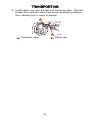
1
! WARNING
The engine exhaust from this product contains chemicals
known to the state of California to cause cancer, birth defects
or other reproductive harm.
i
90-10261080 1008
25/30 2-Stroke
EPA Emissions Regulations
Outboards sold by Mercury Marine in the United States are
certified to the United States Environmental Protection
Agency as conforming to the requirements of the regulations
for the control of air pollution from new outboard motors. This
certification is contingent on certain adjustments being set to
factory standards. For this reason, the factory procedure for
servicing the product must be strictly followed and, wherever
practicable, returned to the original intent of the design.
Maintenance, replacement, or repair of the emission
control devices and systems may be performed by any
marine engine repair establishment or individual.
Engines are labeled with an Emission Control Information
decal as permanent evidence of EPA certification.
© 2008 Mercury Marine
Thank You
for your purchase of one of the finest outboards available. You
have made a sound investment in boating pleasure. Your
outboard has been manufactured by Mercury Marine, a world
leader in marine technology and outboard manufacturing
since 1939. These years of experience have been committed
to the goal of producing the finest quality products. This led to
Mercury Marine's reputation for strict quality control,
excellence, durability, lasting performance and being the best
at providing after the sale support.
Please read this manual carefully before operating your
outboard. This manual has been prepared to assist you in the
operation, safe use and care of your outboard.
All of us at Mercury Marine took pride in building your outboard
and wish you many years of happy and safe boating.
Again, thank you for your confidence in Mercury Marine.
Warranty Message
The product you have purchased comes with a limited warranty
from Mercury Marine, the terms of the warranty are set forth in the
Warranty Information Section of this manual. The warranty
statement contains a description of what is covered, what is not
covered, the duration of coverage, how to best obtain warranty
coverage, important disclaimers and limitations of damages,
and other related information. Please review this important
information.
The description and specifications contained herein were in effect
at the time this manual was approved for printing. Mercury Marine,
whose policy is one of continued improvement, reserves the right
to discontinue models at any time, to change specifications,
designs, methods, or procedures without notice and without
incurring obligation.
Mercury Marine, Fond du Lac, Wisconsin U.S.A.
Litho in U.S.A.
© 2008, Mercury Marine
Mercury, Mercury Marine, MerCruiser, Mercury MerCruiser,
Mercury Racing, Mercury Precision Parts, Mercury Propellers,
Mariner, Quicksilver, #1 On The Water, Alpha, Bravo, Pro Max,
OptiMax, Sport‑Jet, K‑Planes, MerCathode, RideGuide,
SmartCraft, Zero Effort, M with Waves logo, Mercury with Waves
logo, and SmartCraft logo are all registered trademarks of
Brunswick Corporation. Mercury Product Protection logo is a
registered service mark of Brunswick Corporation.
Declaration of Conformity
If the outboard motor’s serial number plate contains the CE mark
in the lower left‑hand corner, the following statement applies:
This outboard motor manufactured by Mercury Marine, Fond du
Lac, WI, USA or Marine Power Europe Inc. Park Industriel, de
Petit‑Rechain, Belgium complies with the requirements of the
following directives and standards, as amended:
Recreational Craft Directive:
94/25/EC
Owner's manual (A.2.5)
ISO 10240
ii
Handling characteristics (A.4)
ISO 8665
Outboard engine starting (A.5.1.4) ISO 11547
Fuel tanks (A.5.2.2)
ISO 13591; ISO 8469
General steering system
ABYC P‑17
Safety of Machinery Directive
98/37/EC
Principles of safety integration
(1.1.2)
EN 292‑1; EN 292‑2; EN 1050
Noise (1.5.8)
ICOMIA 39/94
Vibration
ICOMIA 38/94
Electromagnetic Compatibility
Directive
89/336/EC
Generic emission standard
EN 50081‑1
Generic immunity standard
EN 50082‑1
Vehicles, boats and internal
combustion engine driven devices ‑ SAE J551 (CISPR 12)
radio disturbance characteristics
Electrostatic discharge testing
EN 61000‑6‑2; EN 61000‑4‑2; EN
61000‑4‑3
This declaration is issued under the sole responsibility of Mercury
Marine and Marine Power Europe.
Patrick C. Mackey
President, Mercury Marine, Fond du Lac, WI USA
European Regulations Contact:
Regulations and Product Safety Department, Mercury Marine,
Fond du Lac, WI USA
iii
Mercury Premier Service
Mercury evaluates the service performance of its dealers and
assigns its highest rating of "Mercury Premier" to those
demonstrating an exceptional commitment to service.
Earning a Mercury Premier Service rating means a dealer:
• Achieves a high 12 month service CSI (Customer Satisfaction
Index) score for warranty service.
• Possesses all necessary service tools, test equipment,
manuals and parts books.
• Employs at least one Certified or Master technician.
• Provides timely service for all Mercury Marine customers.
• Offers extended service hours and mobile service, when
appropriate.
• Uses, displays and stocks adequate inventory of genuine
Mercury Precision Parts.
• Offers a clean, neat shop with well organized tools and service
literature.
iv
TABLE OF CONTENTS
Warranty Information
Transfer of Warranty....................................................................1
Transfer of Mercury Product Protection (Extended Service
Coverage) Plan............................................................................1
Warranty Registration United States And Canada......................2
Outboard Limited Warranty..........................................................3
3 Year Limited Warranty Against Corrosion................................6
Warranty Coverage and Exclusions............................................9
GENERAL INFORMATION
Boater's Responsibilities............................................................12
Before Operating Your Outboard...............................................12
Boat Horsepower Capacity........................................................13
High‑Speed and High‑Performance Boat Operation................. 13
Outboard Remote Control Models.............................................13
Remote Steering Notice............................................................. 14
Lanyard Stop Switch..................................................................15
Protecting People in the Water..................................................17
Passenger Safety Message ‑ Pontoon Boats and Deck Boats.. 18
Wave and Wake Jumping..........................................................19
Impact with Underwater Hazards............................................... 20
Exhaust Emissions.................................................................... 21
Selecting Accessories for Your Outboard..................................23
Safe Boating Suggestions......................................................... 23
Recording Serial Number.......................................................... 25
25/30 Specifications................................................................... 26
Components: 25/30M................................................................ 27
INSTALLATION
Installing Outboard..................................................................... 34
Installing the Remote Control Device (Right‑Hand Steering).... 36
Attaching the Steering Link Rod................................................45
Battery Installation ....................................................................46
Propeller Selection..................................................................... 48
v
TABLE OF CONTENTS
TRANSPORTING
Trailering Boat/Outboard...........................................................49
Removing the Motor..................................................................49
Transporting Portable Fuel Tanks.............................................50
FUEL & OIL
Fuel Recommendations.............................................................52
Oil Recommendation.................................................................53
Mixing Fuel and Oil....................................................................54
Filling Fuel Tank........................................................................54
FEATURES & CONTROLS
Remote Control Features..........................................................56
Tilting Outboard ........................................................................56
Shallow Water Operation...........................................................57
Trim Adjustment.........................................................................58
Steering Friction Adjustment...................................................... 59
Trim Tab Adjustment.................................................................60
OPERATION
Pre‑Starting Check List..............................................................62
Operating in Freezing Temperatures.........................................62
Operating in Saltwater or Polluted Water..................................62
Operating at High Elevations.....................................................63
Engine Break‑in Procedure........................................................ 63
Starting the Engine....................................................................64
Warm‑Up...................................................................................70
Gear Shifting..............................................................................71
Stopping the Engine..................................................................73
Emergency Starting...................................................................75
vi
TABLE OF CONTENTS
MAINTENANCE
Outboard Care...........................................................................77
EPA Regulations........................................................................ 77
EPA Emissions..........................................................................78
Inspection and Maintenance Schedule......................................78
Flushing the Cooling System.....................................................80
Top Cowl Removal and Installation...........................................81
Battery Inspection .....................................................................82
Fuel System...............................................................................82
Fuse Replacement ‑ Electric Start Remote Control Models......84
Corrosion Control Anode...........................................................84
Propeller Replacement..............................................................85
Spark Plug Inspection and Replacement................................... 89
Lubrication Points......................................................................90
Gearcase Lubrication................................................................. 90
Submerged Outboard................................................................92
STORAGE
Storage Preparation................................................................... 93
Protecting External Outboard Components...............................94
Protecting Internal Engine Components....................................94
Gearcase...................................................................................95
Positioning Outboard for Storage..............................................95
Battery Storage..........................................................................95
TROUBLESHOOTING
Starter Motor Will Not Crank The Engine (Electric Start Models)
...................................................................................................96
Engine Will Not Start..................................................................96
Engine Runs Erratically.............................................................96
Performance Loss......................................................................97
Battery Will Not Hold Charge.....................................................97
vii
TABLE OF CONTENTS
ASSOCIATED PARTS
Associated Parts........................................................................98
ACCESSORIES
Accessories...............................................................................99
WIRING DIAGRAMS
Wiring Diagrams......................................................................103
OWNER SERVICE ASSISTANCE
Local Repair Service................................................................ 112
Service Away from Home........................................................112
Parts and Accessories Inquiries..............................................112
Service Assistance..................................................................112
Mercury Marine Service Offices...............................................113
MAINTENANCE LOG
Maintenance Log.....................................................................115
viii
WARRANTY INFORMATION
Transfer of Warranty
The limited warranty is transferable to a subsequent purchaser, but
only for the remainder of the unused portion of the limited warranty.
This will not apply to products used for commercial applications.
To transfer the warranty to the subsequent owner, send or fax a
copy of the bill of sale or purchase agreement, new owner’s name,
address and engine serial number to Mercury Marine’s warranty
registration department. In the United States and Canada, mail to:
Mercury Marine
Attn: Warranty Registration Department
W6250 W. Pioneer Road
P.O. Box 1939
Fond du Lac, WI 54936-1939
920-929-5054
Fax +1 920 929 5893
Upon processing the transfer of warranty, Mercury Marine will send
registration verification to the new owner of the product by mail.
There is no charge for this service.
For products purchased outside the United States and Canada,
contact the distributor in your country, or the Marine Power Service
Center closest to you.
Transfer of Mercury Product Protection (Extended
Service Coverage) Plan
The remaining coverage period of the Product Protection Plan is
transferable to the subsequent purchaser of the engine within thirty
(30) days from the date of sale. Contracts not transferred within
thirty (30) days of the subsequent purchase will no longer be valid
and the product will no longer be eligible for coverage under the
terms of the contract.
To transfer the plan to the subsequent owner, contact Mercury
Product Protection or authorized dealer to receive a Request for
Transfer form. Submit to Mercury Product Protection a receipt/bill
of sale, a completed Request of Transfer form, and a check
payable to Mercury Marine in the amount of $50.00 (per engine)
to cover the transfer fee.
1
WARRANTY INFORMATION
Plan coverage is not transferable from one product to another
product or for non‑eligible applications.
The Certified Pre‑Owned engine plans are not transferable.
For help or assistance, contact Mercury Product Protection
Department at 1‑888‑427‑5373 from 7:30 a.m. to 4:30 p.m. CST,
Monday ‑ Friday or email [email protected].
Warranty Registration United States And Canada
Outside United States and Canada ‑ Check with your local
distributor.
1. You may change your address at any time, including at time
of warranty claim, by calling Mercury Marine or sending a letter
or fax with your name, old address, new address, and engine
serial number to Mercury Marine’s warranty registration
department. Your dealer can also process this change of
information.
Mercury Marine
Attn: Warranty Registration Department
W6250 W. Pioneer Road
P.O. Box 1939
Fond du Lac, WI 54936-1939
920-929-5054
Fax 920-929-5893
NOTE: Registration lists must be maintained by Mercury Marine
and any dealer on marine products sold in the United States,
should a safety recall notification under the Federal Safety Act be
required.
2. To be eligible for warranty coverage, the product must be
registered with Mercury Marine. At the time of sale, the dealer
should complete the warranty registration and immediately
submit it to Mercury Marine via MercNET, E‑mail, or mail.
Upon receipt of this warranty registration, Mercury Marine will
record the registration.
2
WARRANTY INFORMATION
3. Upon processing the warranty registration, Mercury Marine
will send registration verification by mail to the purchaser of
the product. If this registration verification is not received
within 30 days, please contact your selling dealer immediately.
Warranty coverage is not effective until your product is
registered with Mercury Marine.
Outboard Limited Warranty
Outside the United States and Canada ‑ Check with your local
distributor.
WHAT IS COVERED: Mercury Marine warrants its new Outboard
and Jet products to be free of defects in material and workmanship
during the period described below.
DURATION OF COVERAGE: This limited warranty provided
coverage for one (1) year from either the date the product is first
sold, or the date on which the product is first put into service,
whichever occurs first. The repair or replacement of parts, or the
performance of service under this warranty, does not extend the
life of this warranty beyond its original expiration date. Unexpired
warranty coverage can be transferred from one recreational use
customer to a subsequent recreational use customer upon proper
re‑registration of the product. Unexpired warranty coverage cannot
be transferred either to or from a commercial use customer.
Commercial use is defined as any work or employment related use
of the product, or any use of the product which generates income,
for any part of the warranty period, even if the product is only
occasionally used for such purposes.
3
WARRANTY INFORMATION
CONDITIONS THAT MUST BE MET IN ORDER TO OBTAIN
WARRANTY COVERAGE: Warranty coverage is available only to
retail customers that purchase from a dealer authorized by
Mercury Marine to distribute the product in the country in which the
sale occurred, and then only after the Mercury Marine specified
pre‑delivery inspection process is completed and documented.
Warranty coverage becomes available upon proper registration of
the product by the authorized dealer. Routine maintenance
outlined in the Operation and Maintenance Manual must be timely
performed in order to maintain warranty coverage. Mercury Marine
reserves the right to make warranty coverage contingent upon
proof of proper maintenance.
WHAT MERCURY WILL DO: Mercury's sole and exclusive
obligation under this warranty is limited to, at our option, repairing
a defective part, replacing such part or parts with new or Mercury
Marine certified re‑manufactured parts, or refunding the purchase
price of the Mercury product. Mercury reserves the right to improve
or modify products from time to time without assuming an
obligation to modify products previously manufactured.
HOW TO OBTAIN WARRANTY COVERAGE: The customer
must provide Mercury with a reasonable opportunity to repair, and
reasonable access to the product for warranty service. Warranty
claims shall be made by delivering the product for inspection to a
Mercury dealer authorized to service the product. If purchaser
cannot deliver the product to such a dealer, written notice must be
given to Mercury. We will then arrange for the inspection and any
covered repair. Purchaser in that case shall pay for all related
transportation charges and/or travel time. If the service provided is
not covered by this warranty, purchaser shall pay for all related
labor and material, and any other expenses associated with that
service. Purchaser shall not, unless requested by Mercury, ship
the product or parts of the product directly to Mercury. Proof of
registered ownership must be presented to the dealer at the time
warranty service is requested in order to obtain coverage.
4
WARRANTY INFORMATION
WHAT IS NOT COVERED: This limited warranty does not cover
routine maintenance items, tune ups, adjustments, normal wear
and tear, damage caused by abuse, abnormal use, use of a
propeller or gear ratio that does not allow the engine to run in its
recommended wide‑open‑throttle RPM range (see the Operation
and Maintenance Manual), operation of the product in a manner
inconsistent with the recommended operation/duty cycle section
of the Operation and Maintenance Manual, neglect, accident,
submersion,
improper
installation
(proper
installation
specifications and techniques are set forth in the installation
instructions for the product), improper service, use of an accessory
or part not manufactured or sold by us, jet pump impellers and
liners, operation with fuels, oils or lubricants which are not suitable
for use with the product (see the Operation and Maintenance
Manual), alteration or removal of parts, water entering the engine
through the fuel intake , air intake or exhaust system, or damage
to the product from insufficient cooling water caused by blockage
of the cooling system by a foreign body, running the engine out of
water, mounting the engine too high on the transom, or running the
boat with the engine trimmed out too far. Use of the product for
racing or other competitive activity, or operating with a racing type
lower unit, at any point, even by a prior owner of the product, voids
the warranty.
Expenses related to haul‑out, launch, towing, storage, telephone,
rental, inconvenience, slip fees, insurance coverage, loan
payments, loss of time, loss of income or any other type of
incidental or consequential damages are not covered but this
warranty. Also, expenses associated with the removal and/or
replacement of boat partitions or material caused by boat design
for access to the product are not covered by this warranty.
No individual or entity, including Mercury Marine authorized
dealers, has been given authority by Mercury Marine to make any
affirmation, representation or warranty regarding the product,
other than those contained in the limited warranty, and if made,
shall not be enforceable against Mercury Marine.
For additional information regarding events and circumstances
covered by this warranty, and those that are not, see the Warranty
Coverage section of the Operation and Maintenance Manual,
incorporated by reference into this warranty.
5
WARRANTY INFORMATION
DISCLAIMERS AND LIMITATIONS:
THE IMPLIED WARRANTIES OF MERCHANTABILITY AND FITNESS FOR A
PARTICULAR PURPOSE ARE EXPRESSLY DISCLAIMED. TO THE EXTENT
THAT THEY CANNOT BE DISCLAIMED, THE IMPLIED WARRANTIES ARE
LIMITED IN DURATION TO THE LIFE OF THE EXPRESS WARRANTY.
INCIDENTAL AND CONSEQUENTIAL DAMAGES ARE EXCLUDED FROM
COVERAGE UNDER THIS WARRANTY. SOME STATES/COUNTRIES DO
NOT ALLOW FOR THE DISCLAIMERS, LIMITATIONS AND EXCLUSIONS
IDENTIFIED ABOVE, AS A RESULT, THEY MAY NOT APPLY TO YOU. THIS
WARRANTY GIVES YOU SPECIFIC LEGAL RIGHTS, AND YOU MAY ALSO
HAVE OTHER LEGAL RIGHTS WHICH VARY FROM STATE TO STATE AND
COUNTRY TO COUNTRY.
3 Year Limited Warranty Against Corrosion
WHAT IS COVERED: Mercury Marine warrants that each new
Mercury, Mariner, Mercury Racing, Sport Jet, M2 Jet Drive, Tracker
by Mercury Marine Outboard, Mercury MerCruiser Inboard or
Sterndrive Engine (Product) will not be rendered inoperative as a
direct result of corrosion for the period of time described below.
DURATION OF COVERAGE: This limited corrosion warranty
provides coverage for three (3) years from either the date the
product is first sold, or the date on which the product is first put into
service, whichever occurs first. The repair or replacement of parts,
or the performance of service under this warranty does not extend
the life of this warranty beyond its original expiration date.
Unexpired warranty coverage can be transferred to subsequent
(non‑commercial use) purchaser upon proper re‑registration of the
product.
6
WARRANTY INFORMATION
CONDITIONS THAT MUST BE MET IN ORDER TO OBTAIN
WARRANTY COVERAGE: Warranty coverage is available only to
retail customers that purchase from a Dealer authorized by
Mercury Marine to distribute the product in the country in which the
sale occurred, and then only after the Mercury Marine specified
pre‑delivery inspection process is completed and documented.
Warranty coverage becomes available upon proper registration of
the product by the authorized dealer. Corrosion prevention devices
specified in the Operation and Maintenance Manual must be in use
on the boat, and routine maintenance outlined in the Operation and
Maintenance Manual must be timely performed (including without
limitation the replacement of sacrificial anodes, use of specified
lubricants, and touch‑up of nicks and scratches) in order to
maintain warranty coverage. Mercury Marine reserves the right to
make warranty coverage contingent upon proof of proper
maintenance.
WHAT MERCURY WILL DO: Mercury's sole and exclusive
obligation under this warranty is limited to, at our option, repairing
a corroded part, replacing such part or parts with new or Mercury
Marine certified re‑manufactured parts, or refunding the purchase
price of the Mercury product. Mercury reserves the right to improve
or modify products from time to time without assuming an
obligation to modify products previously manufactured.
HOW TO OBTAIN WARRANTY COVERAGE: The customer must
provide Mercury with a reasonable opportunity to repair, and
reasonable access to the product for warranty service. Warranty
claims shall be made by delivering the product for inspection to a
Mercury dealer authorized to service the product. If purchaser
cannot deliver the product to such a dealer, written notice must be
given to Mercury. We will then arrange for the inspection and any
covered repair. Purchaser in that case shall pay for all related
transportation charges and/or travel time. If the service provided is
not covered by this warranty, purchaser shall pay for all related
labor and material, and any other expenses associated with that
service. Purchaser shall not, unless requested by Mercury, ship
the product or parts of the product directly to Mercury. Proof of
registered ownership must be presented to the dealer at the time
warranty service is requested in order to obtain coverage.
7
WARRANTY INFORMATION
WHAT IS NOT COVERED: This limited warranty does not cover
electrical system corrosion; corrosion resulting from damage,
corrosion which causes purely cosmetic damage, abuse or
improper service; corrosion to accessories, instruments, steering
systems; corrosion to factory installed jet drive unit; damage due
to marine growth; product sold with less than a one year limited
Product warranty; replacement parts (parts purchased by
customer); products used in a commercial application.
Commercial use is defined as any work or employment related use
of the product, or any use of the product which generates income,
for any part of the warranty period, even if the product is only
occasionally used for such purposes.
Corrosion damage caused by stray electrical currents (on‑shore
power connections, nearby boats, submerged metal) is not
covered by this corrosion warranty and should be protected
against by the use of a corrosion protection system, such as the
Mercury Precision Parts or Quicksilver MerCathode system and/
or Galvanic Isolator. Corrosion damage caused by improper
application of copper base anti‑fouling paints is also not covered
by this limited warranty. If anti‑fouling protection is required,
Tri‑Butyl‑Tin‑Adipate (TBTA) base anti‑fouling paints are
recommended on Outboard and MerCruiser boating applications.
In areas where TBTA base paints are prohibited by law, copper
base paints can be used on the hull and transom. Do not apply
paint to the outboard or MerCruiser product. In addition, care must
be taken to avoid an electrical interconnection between the
warranted product and the paint. For MerCruiser product, an
unpainted gap of at least 38 mm (1.5 in.) should be left around the
transom assembly. Refer to the Operation and Maintenance
Manual for additional details.
For additional information regarding events and circumstances
covered by this warranty, and those that are not, see the Warranty
Coverage section of the Operation and Maintenance Manual,
incorporated by reference into this warranty.
8
WARRANTY INFORMATION
DISCLAIMERS AND LIMITATIONS:
THE IMPLIED WARRANTIES OF MERCHANTABILITY AND FITNESS FOR A
PARTICULAR PURPOSE ARE EXPRESSLY DISCLAIMED. TO THE EXTENT
THAT THEY CANNOT BE DISCLAIMED, THE IMPLIED WARRANTIES ARE
LIMITED IN DURATION TO THE LIFE OF THE EXPRESS WARRANTY.
INCIDENTAL AND CONSEQUENTIAL DAMAGES ARE EXCLUDED FROM
COVERAGE UNDER THIS WARRANTY. SOME STATES/COUNTRIES DO
NOT ALLOW FOR THE DISCLAIMERS, LIMITATIONS AND EXCLUSIONS
IDENTIFIED ABOVE, AS A RESULT, THEY MAY NOT APPLY TO YOU. THIS
WARRANTY GIVES YOU SPECIFIC LEGAL RIGHTS, AND YOU MAY ALSO
HAVE OTHER LEGAL RIGHTS WHICH VARY FROM STATE TO STATE AND
COUNTRY TO COUNTRY.
Warranty Coverage and Exclusions
The purpose of this section is to help eliminate some of the more
common misunderstandings regarding warranty coverage. The
following information explains some of the types of services that
are not covered by warranty. The provisions set forth following
have been incorporated by reference into the Three Year Limited
Warranty Against Corrosion Failure, the International Limited
Outboard Warranty, and the United States and Canada Limited
Outboard Warranty.
Keep in mind that warranty covers repairs that are needed within
the warranty period because of defects in material and
workmanship. Installation errors, accidents, normal wear, and a
variety of other causes that affect the product are not covered.
Warranty is limited to defects in material or workmanship, but only
when the consumer sale is made in the country to which
distribution is authorized by us.
Should you have any questions concerning warranty coverage,
contact your authorized dealer. They will be pleased to answer any
questions that you may have.
GENERAL EXCLUSIONS FROM WARRANTY
1. Minor adjustments and tune‑ups, including checking, cleaning
or adjusting spark plugs, ignition components, carburetor
settings, filters, belts, controls, and checking lubrication made
in connection with normal services.
9
WARRANTY INFORMATION
2. Factory installed jet drive units ‑ Specific parts excluded from
the warranty are: The jet drive impeller and jet drive liner
damaged by impact or wear, and water damaged drive shaft
bearings as a result of improper maintenance.
3. Damage caused by neglect, lack of maintenance, accident,
abnormal operation or improper installation or service.
4. Haul out, launch, towing charges, removal and/or replacement
of boat partitions or material because of boat design for
necessary access to the product, all related transportation
charges and/or travel time, etc. Reasonable access must be
provided to the product for warranty service. Customer must
deliver product to an authorized dealer.
5. Additional service work requested by customer other than that
necessary to satisfy the warranty obligation.
6. Labor performed by other than an authorized dealer may be
covered only under following circumstances: When performed
on emergency basis (providing there are no authorized
dealers in the area who can perform the work required or have
no facilities to haul out, etc., and prior factory approval has
been given to have the work performed at this facility).
7. All incidental and/or consequential damages (storage
charges, telephone or rental charges of any type,
inconvenience or loss of time or income) are the owner's
responsibility.
8. Use of other than Mercury Precision or Quicksilver parts when
making warranty repairs.
9. Oils, lubricants or fluids changed as a matter of normal
maintenance is customer's responsibility unless loss or
contamination of same is caused by product failure that would
be eligible for warranty consideration.
10. Participating in or preparing for racing or other competitive
activity or operating with a racing type lower unit.
11. Engine noise does not necessarily indicate a serious engine
problem. If diagnosis indicates a serious internal engine
condition which could result in a failure, condition responsible
for noise should be corrected under the warranty.
10
WARRANTY INFORMATION
12. Lower unit and/or propeller damage caused by striking a
submerged object is considered a marine hazard.
13. Water entering engine through the fuel intake, air intake or
exhaust system or submersion.
14. Failure of any parts caused by lack of cooling water, which
results from starting motor out of water, foreign material
blocking inlet holes, motor being mounted too high or trimmed
too far out.
15. Use of fuels and lubricants which are not suitable for use with
or on the product. Refer to the Maintenance section.
16. Our limited warranty does not apply to any damage to our
products caused by the installation or use of parts and
accessories which are not manufactured or sold by us.
Failures which are not related to the use of those parts or
accessories are covered under warranty if they otherwise
meet the terms of the limited warranty for that product.
11
GENERAL INFORMATION
Boater's Responsibilities
The operator (driver) is responsible for the correct and safe
operation of the boat and safety of its occupants and general
public. It is strongly recommended that each operator (driver) read
and understand this entire manual before operating the outboard.
Be sure at least one additional person onboard is instructed in the
basics of starting and operating the outboard and boat handling in
case the driver is unable to operate the boat.
Before Operating Your Outboard
Read this manual carefully. Learn how to operate your outboard
properly. If you have any questions, contact your dealer.
Safety and operating information that is practiced, along with using
good common sense, can help prevent personal injury and product
damage.
This manual as well as safety labels posted on the outboard use
the following safety alerts to draw your attention to special safety
instructions that should be followed.
! DANGER
Indicates a hazardous situation which, if not avoided, will result
in death or serious injury.
! WARNING
Indicates a hazardous situation which, if not avoided, could result
in death or serious injury.
! CAUTION
Indicates a hazardous situation which, if not avoided, could result
in minor or moderate injury.
NOTICE
Indicates a situation which, if not avoided, could result in engine
or major component failure.
12
GENERAL INFORMATION
Boat Horsepower Capacity
! WARNING
Exceeding the boat's maximum horsepower rating can cause
serious injury or death. Overpowering the boat can affect boat
control and flotation characteristics or break the transom. Do not
install an engine that exceeds the boat's maximum power rating.
Do not overpower or overload your boat. Most boats will carry a
required capacity plate indicating the maximum acceptable power
and load as determined by the manufacturer following certain
federal guidelines. If in doubt, contact your dealer or the boat
manufacturer.
U.S. COAST GUARD CAP ACITY
MAXIMUM HORSEPOWER XXX
MAXIMUM PERSON
CAPACITY (POUNDS)
XXX
MAXIMUM WEIGHT
CAPACITY
XXX
26777
High‑Speed and High‑Performance Boat Operation
If your outboard is to be used on a high‑speed or high‑performance
boat with which you are unfamiliar, we recommend that you never
operate it at its high speed capability without first requesting an
initial orientation and familiarization demonstration ride with your
dealer or an operator experienced with your boat/outboard
combination. For additional information, obtain a copy of our
Hi‑Performance Boat Operation booklet from your dealer,
distributor, or Mercury Marine.
Outboard Remote Control Models
The remote control connected to your outboard must be equipped
with a start in neutral only protection device. This prevents the
engine from starting when the shift is actuated in any position other
than neutral.
13
GENERAL INFORMATION
! WARNING
Starting the engine with the drive in gear can cause serious injury
or death. Never operate a boat that does not have a
neutral‑safety‑protection device.
37991
Remote Steering Notice
! WARNING
Improper fasteners or improper installation procedures can result
in loosening or disengagement of the steering link rod. This can
cause a sudden, unexpected loss of boat control, resulting in
serious injury or death due to occupants being thrown within or
out of the boat. Always use required components and follow
instructions and torque procedures.
The steering link rod that connects the steering cable to the engine
must be fastened utilizing self‑locking nuts. These self‑locking nuts
must never be replaced with common nuts (non‑locking) as they
will work loose and vibrate off, freeing the link rod to disengage.
a
a
a - Self‑locking nuts
14
28984
GENERAL INFORMATION
Lanyard Stop Switch
The purpose of a lanyard stop switch is to turn off the engine when
the operator moves far enough away from the operator's position
(as in accidental ejection from the operator's position) to activate
the switch. Tiller handle outboards and some remote control units
are equipped with a lanyard stop switch. A lanyard stop switch can
be installed as an accessory–generally on the dashboard or side
adjacent to the operator's position.
The lanyard is a cord usually 122–152 cm (4–5 feet) in length when
stretched out, with an element on one end made to be inserted into
the switch and a lanyard cord on the other end for attaching to the
operator. The lanyard is coiled to make its at‑rest condition as short
as possible to minimize the likelihood of lanyard entanglement with
nearby objects. Its stretched‑out length is made to minimize the
likelihood of accidental activation should the operator choose to
move around in an area close to the normal operator's position. If
it is desired to have a shorter lanyard, wrap the lanyard around the
operator's wrist or leg, or tie a knot in the lanyard.
b
a
21629
b - Lanyard stop switch
a - Lanyard cord
15
GENERAL INFORMATION
Important Safety Information: The purpose of a lanyard stop switch
is to stop the engine when the operator moves far enough away
from the operator's position to activate the switch. This would occur
if the operator accidentally falls overboard or moves within the boat
a sufficient distance from the operator's position. Falling overboard
and accidental ejections are more likely to occur in certain types
of boats such as low sided inflatables, bass boats, high
performance boats, and light, sensitive handling fishing boats
operated by a hand tiller. Falling overboard and accidental
ejections are also likely to occur as a result of poor operating
practices such as sitting on the back of the seat or gunwale at
planing speeds, standing at planing speeds, sitting on elevated
fishing boat decks, operating at planing speeds in shallow or
obstacle infested waters, releasing your grip on a steering wheel
or tiller handle that is pulling in one direction, drinking alcohol or
consuming drugs, or daring high‑speed boat maneuvers.
While activation of the lanyard stop switch will stop the engine
immediately, a boat will continue to coast for some distance
depending upon the velocity and degree of any turn at shutdown.
However, the boat will not complete a full circle. While the boat is
coasting, it can cause injury to anyone in the boat's path as
seriously as the boat would when under power.
We strongly recommend that other occupants be instructed on
proper starting and operating procedures should they be required
to operate the engine in an emergency (for example, if the operator
is accidentally ejected).
Accidental or unintended activation of the switch during normal
operation is also a possibility. This could cause any, or all, of the
following potentially hazardous situations:
• Occupants could be thrown forward due to unexpected loss
of forward motion–a particular concern for passengers in the
front of the boat who could be ejected over the bow and
possibly struck by the gearcase or propeller.
• Loss of power and directional control in heavy seas, strong
current, or high winds.
• Loss of control when docking.
16
GENERAL INFORMATION
Protecting People in the Water
WHILE YOU ARE CRUISING
It is very difficult for a person standing or floating in the water to
take quick action to avoid a boat heading in his/her direction, even
at slow speed.
21604
Always slow down and exercise extreme caution any time you are
boating in an area where there might be people in the water.
Whenever a boat is moving (coasting) and the outboard gear shift
is in neutral position, there is sufficient force by the water on the
propeller to cause the propeller to rotate. This neutral propeller
rotation can cause serious injury.
WHILE BOAT IS STATIONARY
! WARNING
A spinning propeller, a moving boat, or any solid device attached
to the boat can cause serious injury or death to swimmers. Stop
the engine immediately whenever anyone in the water is near
your boat.
Shift outboard into neutral and shut off the engine before allowing
people to swim or be in the water near your boat.
17
GENERAL INFORMATION
Passenger Safety Message ‑ Pontoon Boats and
Deck Boats
Whenever the boat is in motion, observe the location of all
passengers. Do not allow any passengers to stand or use seats
other than those designated for traveling faster than idle speed. A
sudden reduction in boat speed, such as plunging into a large wave
or wake, a sudden throttle reduction, or a sharp change of boat
direction, could throw them over the front of the boat. Falling over
the front of the boat between the two pontoons will position them
to be run over by the outboard.
BOATS HAVING AN OPEN FRONT DECK
No one should ever be on the deck in front of the fence while the
boat is in motion. Keep all passengers behind the front fence or
enclosure.
Persons on the front deck could easily be thrown overboard or
persons dangling their feet over the front edge could get their legs
caught by a wave and pulled into the water.
26782
! WARNING
Sitting or standing in an area of the boat not designed for
passengers at speeds above idle can cause serious injury or
death. Stay back from the front end of deck boats or raised
platforms and remain seated while the boat is in motion.
BOATS WITH FRONT MOUNTED, RAISED PEDESTAL
FISHING SEATS
Elevated fishing seats are not intended for use when the boat is
traveling faster than idle or trolling speed. Sit only in seats
designated for traveling at faster speeds.
18
GENERAL INFORMATION
Any unexpected, sudden reduction in boat speed could result in
the elevated passenger falling over the front of the boat.
26783
Wave and Wake Jumping
Operating recreational boats over waves and wake is a natural part
of boating. However, when this activity is done with sufficient speed
to force the boat hull partially or completely out of the water, certain
hazards arise, particularly when the boat reenters the water.
26784
The primary concern is the boat changing direction while in the
midst of the jump. In such case, the landing may cause the boat to
veer violently in a new direction. Such a sharp change in direction
can cause occupants to be thrown out of their seats, or out of the
boat.
! WARNING
Wave or wake jumping can cause serious injury or death from
occupants being thrown within or out of the boat. Avoid wave or
wake jumping whenever possible.
19
GENERAL INFORMATION
There is another less common hazardous result from allowing your
boat to launch off a wave or wake. If the bow of your boat pitches
down far enough while airborne, upon water contact it may
penetrate under the water surface and submarine for an instant.
This will bring the boat to a nearly instantaneous stop and can send
the occupants flying forward. The boat may also steer sharply to
one side.
Impact with Underwater Hazards
Reduce speed and proceed with caution whenever you drive a
boat in shallow water areas, or in areas where you suspect
underwater obstacles may exist which could be struck by the
outboard or the boat bottom. The most important thing you can do
to help reduce injury or impact damage from striking a floating or
underwater object is to control the boat speed. Under these
conditions, boat speed should be kept to a minimum planing speed
of 24 to 40 km/h (15 to 25 MPH).
26785
Striking a floating or underwater object could result in an infinite
number of situations. Some of these situations could result in the
following:
• Part of the outboard or the entire outboard could break loose
and fly into the boat.
• The boat could move suddenly in a new direction. Such a
sharp change in direction can cause occupants to be thrown
out of their seats or out of the boat.
• A rapid reduction in speed. This will cause occupants to be
thrown forward, or even out of the boat.
• Impact damage to the outboard and/or boat.
20
GENERAL INFORMATION
Keep in mind, the most important thing you can do to help reduce
injury or impact damage during an impact is control the boat speed.
Boat speed should be kept to a minimum planing speed when
driving in waters known to have underwater obstacles.
After striking a submerged object, stop the engine as soon as
possible and inspect it for any broken or loose parts. If damage is
present or suspected, the outboard should be taken to an
authorized dealer for a thorough inspection and necessary repair.
The boat should also be checked for any hull fractures, transom
fractures, or water leaks.
Operating a damaged outboard could cause additional damage to
other parts of the outboard, or could affect control of the boat. If
continued running is necessary, do so at greatly reduced speeds.
! WARNING
Operating a boat or engine with impact damage can result in
product damage, serious injury, or death. If the vessel
experiences any form of impact, have an authorized Mercury
Marine dealer inspect and repair the vessel or power package.
Exhaust Emissions
BE ALERT TO CARBON MONOXIDE POISONING
Carbon monoxide is present in the exhaust fumes of all internal
combustion engines. This includes the outboards, sterndrives and
inboard engines that propel boats, as well as the generators that
power various boat accessories. Carbon monoxide is a deadly gas
that is odorless, colorless and tasteless.
Early symptoms of carbon monoxide poisoning which should not
be confused with seasickness or intoxication, include headache,
dizziness, drowsiness, and nausea.
! WARNING
Carbon monoxide poisoning can lead to unconsciousness, brain
damage, or death. Keep the boat well ventilated while at rest or
underway and avoid prolonged exposure to carbon monoxide.
21
GENERAL INFORMATION
GOOD VENTILATION
Ventilate passenger area, open side curtains, or forward hatches
to remove fumes.
21622
Example of desired air flow through the boat
POOR VENTILATION
Under certain running and/or wind conditions, permanently
enclosed or canvas enclosed cabins or cockpits with insufficient
ventilation may draw in carbon monoxide. Install one or more
carbon monoxide detectors in your boat.
Although the occurrence is rare, on a very calm day, swimmers
and passengers in an enclosed area of a stationary boat that
contains or is near a running engine may be exposed to a
hazardous level of carbon monoxide.
WHILE BOAT IS STATIONARY
a
b
21626
a - Running the engine when the boat is moored in a confined
space
b - Mooring close to another boat that has its engine running
22
GENERAL INFORMATION
WHILE BOAT IS MOVING
a
b
21628
a - Running the boat with the trim angle of the bow too high
b - Running the boat with no forward hatches open
Selecting Accessories for Your Outboard
Genuine Mercury Precision or Quicksilver Accessories have been
specifically designed and tested for your outboard. These
accessories are available from Mercury Marine dealers.
IMPORTANT: Check with your dealer before installing
accessories. The misuse of approved accessories or the use of
non‑approved accessories can damage the product.
Some accessories not manufactured or sold by Mercury Marine
are not designed to be safely used with your outboard or outboard
operating system. Acquire and read the installation, operation, and
maintenance manuals for all your selected accessories.
Safe Boating Suggestions
In order to safely enjoy the waterways, familiarize yourself with
local and other governmental boating regulations and restrictions,
and consider the following suggestions.
Use flotation devices. Have an approved personal flotation device
of suitable size for each person aboard (it is the law) and have it
readily accessible.
Do not overload your boat. Most boats are rated and certified for
maximum load (weight) capacities (refer to your boat capacity
plate). If in doubt, contact your dealer or the boat's manufacturer.
Perform safety checks and required maintenance. Follow a regular
schedule and ensure that all repairs are properly made.
23
GENERAL INFORMATION
Know and obey all nautical rules and laws of the waterways. Boat
operators should complete a boating safety course. Courses are
offered in the U.S.A. by 1) the U.S. Coast Guard Auxiliary, 2) the
Power Squadron, 3) the Red Cross, and 4) your state boating law
enforcement agency. Inquiries may be made to the Boating
Hotline, 1‑800‑368‑5647 or the Boat U.S. Foundation information
number 1‑800‑336‑BOAT.
Make sure everyone in the boat is properly seated. Do not allow
anyone to sit or ride on any part of the boat that was not intended
for such use. This includes the back of seats, gunwales, transom,
bow, decks, raised fishing seats, any rotating fishing seat; or
anywhere that an unexpected acceleration, sudden stopping,
unexpected loss of boat control, or sudden boat movement could
cause a person to be thrown overboard or into the boat.
Never be under the influence of alcohol or drugs while boating (it
is the law). Alcohol or drug use impairs your judgment and greatly
reduces your ability to react quickly.
Prepare other boat operators. Instruct at least one other person on
board in the basics of starting and operating the outboard, and boat
handling, in case the driver becomes disabled or falls overboard.
Passenger boarding. Stop the engine whenever passengers are
boarding, unloading, or are near the back (stern) of the boat. Just
shifting the outboard into neutral is not sufficient.
Be alert. The operator of the boat is responsible by law to maintain
a proper lookout by sight and hearing. The operator must have an
unobstructed view particularly to the front. No passengers, load,
or fishing seats should block the operator's view when operating
the boat above idle speed.
Never drive your boat directly behind a water‑skier in case the skier
falls. As an example, your boat traveling at 40 km/h (25 MPH) will
overtake a fallen skier 61 m (200 ft) in front of you in 5 seconds.
Watch fallen skiers. When using your boat for waterskiing or similar
activities, always keep a fallen or down skier on the operator's side
of the boat while returning to assist the skier. The operator should
always have the down skier in sight and never back up to the skier
or anyone in the water.
24
GENERAL INFORMATION
Report accidents. Boat operators are required by law to file a
Boating Accident Report with their state boating law enforcement
agency when their boat is involved in certain boating accidents. A
boating accident must be reported if 1) there is loss of life or
probable loss of life, 2) there is personal injury requiring medical
treatment beyond first aid, 3) there is damage to boats or other
property where the damage value exceeds $500.00, or 4) there is
complete loss of the boat. Seek further assistance from local law
enforcement.
Recording Serial Number
It is important to record the serial number and other important
information for future reference.
Please record the serial number of the engine as indicated (on the
lower engine cover and the cylinder block) in the space below. This
number will come in handy in the event of theft and it can help you
to quickly identify the product type.
Serial Number:
Model year:
Model designation:
Year manufactured:
Certified Europe Insignia (as applicable):
25
GENERAL INFORMATION
25/30 Specifications
Model
25M
30M
30EH
30E
Overall length
884 mm (34.8 in.)
600 mm (23.6 in.)
Overrall width
412 mm (16.2 in.)
355 mm (14 in.)
Overrall height
S: 1116 mm (44 in.) ‑ L: 1243 mm (49 in.)
Transom height
S: 435 mm (17.1 in.) ‑ L: 562 mm (22.1 in.)
Weights
Max output PS/(KW)
Full‑throttle RPM
51 kg (112 lb)
55 kg (124
lb)
25 (18.4)
30 (22.1)
5,000 ‑
6,000
5,150 ‑ 5,850
Fuel consumption
13 ltr/hr
Number of cylinders
2
Piston displacement
430 cc (26.2 cu in.)
Cylinder bore
68 mm (2.68 in.)
Piston stroke
59 mm (2.32 in.)
Exhaust system
Through hub exhaust
Cooling system
Water cooled
Starting system
Battery rating
Manual
Electric/Manual
Minimum reserve capacity rating of 100 minutes and
CCA of 350 amps
Ignition
Spark plug
Spark plug gap
CD Ignition
NGK B7HS ‑ 10 or Champion L82C ‑ NGK BPR7HS ‑
10
1.0 mm (0.035 in.)
Alternator
Fuel mixing ratio
12 V, 18 W
50:1 ‑ Regular Gasoline 50 : Oil 1 (Quicksilver TC ‑ WII
or TC ‑ WIIl 2 Cycle)
Fuel tank capacities
25 L (6.6 gal.)
Gear reduction ratio
1.92 : 1
Gear oil
Gear oil volume
54 kg (119 lb)
Quicksilver Gear Lube Premium Blend
280 ml (9.5 fl.oz.)
26
GENERAL INFORMATION
Components: 25/30M
20
11
1
12
2
13
14
3
21
22
15
4
16
5
6
7
8
17
18
9
10
24
19
25 26
27
23
28
MH models
27
37417
GENERAL INFORMATION
1 - Tilt handle
2 - Upper cowl
3 - Water pump indicator hole
4 - Water plug
5 - Reverse Lock Lever
6 - Drive shaft housing
7 - Anti‑ventilation plate
8 - Trim tab
9 - Secondary water intake
10 - Propeller
11 - Starter rope handle
12 - Shift lever
13 - Throttle grip
14 - Clamp screw
15 - Clamp bracket
16 - Trim position pin
17 - Upper oil plug
18 - Cooling water intake
19 - Lower oil plug
20 - Connector B
21 - Stop switch
22 - Choke knob
23 - Fuel tank
24 - Primer valve
25 - Fuel connector
26 - Fuel tank cap
27 - Air vent screw
28 - Fuel Pick Up Elbow
28
29
GENERAL INFORMATION
1
2
11
21
12
22
13
14
3
15
4
16
5
23
24
17
6
7
18
8
19
9
20
10
26
25
27
28
29
30
37461
EH models
30
GENERAL INFORMATION
1 - Tilt handle
2 - Upper cowl
3 - Water pump indicator hole
4 - Water plug
5 - Reverse Lock Lever
6 - Drive shaft housing
7 - Anti‑ventilation plate
8 - Trim tab
9 - Secondary water intake
10 - Propeller
11 - Starter rope handle
12 - Shift lever
13 - Throttle grip
14 - Clamp screw
15 - Clamp bracket
16 - Trim position pin
17 - Battery cable
18 - Upper oil plug
19 - Cooling water intake
20 - Lower oil plug
21 - Connector B
22 - Main switch
23 - Stop switch
24 - Choke knob
25 - Fuel tank
26 - Primer valve
27 - Fuel connector
28 - Fuel tank cap
29 - Air vent screw
30 - Fuel Pick Up Elbow
31
GENERAL INFORMATION
1
11
2
12
20
13
3
14
4
15
5
16
6
7
17
8
18
9
19
10
26
21
22
27
23
28
24
29
25
30
37463
E models
32
GENERAL INFORMATION
1 - Tilt handle
2 - Upper cowl
3 - Water pump indicator hole
4 - Water plug
5 - Reverse Lock Lever
6 - Drive shaft housing
7 - Anti‑ventilation plate
8 - Trim tab
9 - Secondary water intake
10 - Propeller
11 - Starter rope handle
12 - Shift lever
13 - Clamp screw
14 - Clamp bracket
15 - Trim position pin
16 - Battery cable
17 - Upper oil plug
18 - Cooling water intake
19 - Lower oil plug
20 - Connector B
21 - Remote control box
22 - Main switch
23 - Stop switch
24 - Cord assembly
25 - Fuel tank
26 - Primer valve
27 - Fuel connector
28 - Fuel tank cap
29 - Air vent screw
30 - Fuel Pick Up Elbow
33
INSTALLATION
Installing Outboard
We strongly recommend that your dealer install your outboard and
related accessories ot ensure proper installation and good
performance. If you install the outboard yourself, follow instructions
in the manual which is provided with the outboard.
34
INSTALLATION
NOTE: Most boats are rated and certified in terms of their
maximum horse power limit, and this is shown on the boatt's
certification plate. Do not equip your boat with an outboard that
exceeds this limit. If in doubt, contact your dealer. Do not operate
the engine until it has been securely mounted on the boat in
accordance withthe instructions below.
1. Position the outboard motor at the center of the stern.
a
37508
2. Position the outboard engines about 580 mm (23 in.) apart.
580mm
37509
3. Clearance between anti‑ventilation plate of the motor and
bottom of the boat must be 30 to 50 mm (1.2 to 2 in.). If the
height difference exceeds 30 to 50 m (1.2 to 2 in.) engine
power performance is likely to be reduced as a result of
increased water resistance to the gearcase assembly.
NOTE: Select an outboard motor that allows the clearance shown
below.
35
INSTALLATION
TRANSOM MATCHING
NOTE: Be sure that the Anti‑ventilation plate of the outboard is
below the water surface when running with wide‑open throttle. In
case the above condition cannot be met due to a bottom shape of
your boat, please consult the dealer.
Installing the Remote Control Device (Right‑Hand
Steering)
1. Positioning the remote-control box: Position the remote
control box in a place that will not obstruct handling of the
control levers and switches. Confirm that there is no obstacle
in the passage of remote control cables.
37529
36
INSTALLATION
2. Remote control features
f
e
d
d
g
c
b
c
b
a
h
a
37531
abcd-
Fully opened position
Fully closed position
Throttle
Shift
efgh-
Neutral (N)
Forward (F)
Reverse (R)
Throttle only lever
3. Determining remote control cable length: A guideline for
determining the proper length for a remote control cable is
dimensions A plus B plus 300 mm (1 foot).
A
a
B
37530
a - Center of stern
NOTE: The minimum bend radius for a remote control cable is
typically 203 mm (8 in.). Avoid making sharp bends.
37
INSTALLATION
4. Connecting remote control cable to the remote control
box: Remove the back panel by loosening two screws.
a
37528
a - Back panel
5. Thread the remote control cables through the terminal eyes at
a distance of more than 11 mm (0.43 in.). Securely lock the
terminal eyes with the nut lock.
11mm
b
a
37497
a - Terminal eyes
b - Nut lock
38
INSTALLATION
6. Press the neck of the shift remote control cable down into the
clamp on the housing of the remote control box. Connect the
terminal eye to the shift arm with the pin and E‑ring. Insert a
grommet, supplied with the remote control box, into the clamp.
a
c
b
d
37527
a - Grommet
b - Shift arm pin
c - E‑ring
d - Shift arm
7. Connect the throttle remote control cable to the throttle arm in
a manner similar to the shift remote control cable.
a
b
c
d
37526
c - Throttle arm
d - Shift arm
a - Throttle cable
b - Shift cable
39
INSTALLATION
8. Install the back panel.
a
37528
a - Back panel
9. Install the remote control box with three screws, spacers and
nuts.
c
b
d
e
a
f
37464
a - Screw
b - Remote control box
c - Hull
d - Spacer
e - Washer
f - Nut
40
INSTALLATION
10. Connect the remote control cable to the engine and attach
the cord assembly as shown below.
g
h
i
f
j
e
d
q
c
k
b
o
l
a
p
m
n
abcdefgh-
Steering hook plate
Spacer
Clip
Neck of remote control
cable
Shift remote control
cable
Washer
Sleeve guide B: Fix
remote control cable
to shift lever
Shift lever
i - Advance arm
j - Ball joint
k - Holder cap: Connect
remote control cable to
ball joint
l - Remove grommet from
lower motor cover
m -Throttle remote control
cable
n - Neck of remote control
cable
o - Spacer
p - clip
11. Attach a holder cap and a sleeve guide B
41
37495
INSTALLATION
12. Throttle side: Slide a grommet onto an end of the cable, put
a holder cap on it, and lock it with a nut, as shown.
b
a
c
37502
a - Throttle cable
b - Nut
c - Holder cap
13. Shift side: Attach the sleeve guide B to the shift remote
control cable, and lock it with a nut.
d
a
c
b
37503
a - Neck of remote control
cable
b - Shift remote control
cable
c - Nut
d - Sleeve guide B
14. Connect the remote control cable to the engine.
15. Throttle side: Insert the throttle remote control cable into a
hole of the advancer arm at the lower motor cover, attach the
ball joint to the holder cap at the tip of the remote control cable,
and fasten the remote control cable with a clip. Attach a
grommet to the lower motor cover.
NOTE: Place the control lever in Neutral (N), and the idling lever
in the Fully Closed position.
16. Shift side: Insert the lock pin at the sleeve guide B into the
shift lever attaching hole and turn it 90° to lock it, then fasten
the remote control cable with a clip.
42
INSTALLATION
NOTE: Confirm the motion of the control lever: Turn the control
lever to Forward (F) or Reverse (R) at 32° where the lever is
latched. The shift lever will be moved to the shift‑in position, and
the throttle is fully opened when shifted further. Confirm the
throttle lever is Fully Closed when the control lever is shifted to
Neutral (N). If the throttle is completely closed, position the holder
cap on the engine, and attach it.
43
INSTALLATION
17. Attach the cord assembly: Connect the cord assembly from
the remote control box to respective terminals through the
lower motor cover as illustrated. Fasten the cord assembly
with clamps.
b
h
e
g
d
c
j
c
d
i
b
f
j
i
k
m
a
l
n
s
r
q
o
p
37505
abcdefghij-
Cord assembly
Black terminal
Brown terminal
Green terminal
Red terminal
Rectifier
Terminal holder
Fuse
Clamps
Blue terminal
k - Starter solenoid
l - CD Unit
m -Choke solenoid
n - Starter solenoid bracket
o - Lower motor cover
p - Grommet
q - To remote control box
r - Clamp
s - Screw
44
INSTALLATION
BLK
GRN
BLK
GRN
RED
RED
BLU
WHT
WHT
BLU
YEL
g h
BRN
c d e f
BRN
b
RED
a
YEL
18. Connect the cables to their respective terminals at the cable
terminal holder.
j k
i
l m
37500
abcdefg-
Magnet lead wire
Magnet lead wire
Cord assembly
Fuse wire
CD unit
Cord assembly
CD unit
h - Starter solenoid
i - Rectifier lead wire
j - Stop switch
k - Choke solenoid
l - Stop switch
m -Cord assembly
Attaching the Steering Link Rod
! WARNING
Improper fasteners or improper installation procedures can result
in loosening or disengagement of the steering link rod. This can
cause a sudden, unexpected loss of boat control, resulting in
serious injury or death due to occupants being thrown within or
out of the boat. Always use required components and follow
instructions and torque procedures.
45
INSTALLATION
The steering link rod parts are available and assembled as
illustrated below. Spacers may or may not be required depending
on cable brands.
c
d
e
g d
b
a
f
h
d
a
abcdef-
i
j
k
d
i
Grease
Spacer (option)
Bolt
Washer B
Cushion rubber
Spring
ghijkl-
l
37507
Spacer
Collar
Nut lock
Rod
Washer A
Seal ring
Battery Installation
MOUNTING BATTERY
Follow the battery manufacturer's instructions carefully. Mount
battery securely to the hull in a place free from splashing water.
NOTE: Electric starting outboards must have the battery cables
connected to a battery whenever the engine is running, even if
started manually, as damage to the charging system could result.
BATTERY CONNECTIONS
Connect a red cable to the positive (+) terminal first and a black
cable to the negative (–) terminal of the battery. Put a red cap on
the positive terminal. When disconnecting battery cables, be sure
to disconnect the black cable first, and then the red cable.
46
INSTALLATION
Required battery rating: 12V battery with a recommended
capacity of 70 AH or over.
• Battery cables must be long enough to allow free steering.
• Battery cables must be arranged and protected from damage
during steering.
• With poor cable connections, the starter will fail to start.
• Battery cable terminals should be clean, tight, and correctly
installed. Positive to positive and negative to negative.
• Battery must be fully charged before running the motor.
a
b
37712
a - Red cable
b - Black cable
IMPORTANT: Please follow the instructions below.
• Hydrogen gas is generated when charging a battery. Keep the
battery in a well‑ventilated area during charging. Remove the
battery from the boat; this will protect your hull and interior
from damage. Electric sparks, cigarette smoking, and other
sources of fire must be avoided in the charging area to prevent
explosion of the battery.
• The battery fluid (electrolyte) contains sulfuric acid. If
electrolyte is spilled on the skin or clothes, wash with plenty
of water and consult a medical doctor. Always use safety
glasses and rubber gloves when handling the battery.
47
INSTALLATION
Propeller Selection
For best all around performance from your outboard/boat
combination, select a propeller that allows the engine to operate
in the upper half of the recommended full throttle RPM range with
the
boat
normally
loaded
(refer
to
General
Information-Specifications). This RPM range allows for better
acceleration while maintaining maximum boat speed.
The propeller supplied with your outboard provides the best overall
performance under average operating conditions.
Alternative propellers are available for specific boating
requirements. See your outboard dealer.
AVAILABLE PROPELLERS
Light‑duty boat
Mark
14 (E)
–
13 (D)
11 (C)
Heavy‑duty boat
10 (B)
9 (A)
8 (F)
Dimensions
(blade x
3 x 252 x 3 x 252 x 3 x 250 x 3 x 250 x 3 x 249 x 3 x 260 x
diameter x pitch)
360
332
288
260
236
210
mm
If changing conditions cause the RPM to drop below the
recommended range, such as warmer, more humid weather,
operation at higher elevations, increased boat load, or a dirty boat
bottom/gearcase, a propeller change or cleaning may be required
to maintain performance and ensure the outboard's durability.
Check full‑throttle RPM, using an accurate tachometer, with the
engine trimmed out to a balanced‑steering condition (steering
effort equal in both directions) without causing the propeller to
break loose.
48
TRANSPORTING
Trailering Boat/Outboard
The boat should be trailered with the outboard tilted down in a
vertical operating position.
IMPORTANT: The tilt lock and shallow water drive feature (tiller
handle models) on the outboard are not intended to support the
outboard in the tilted position when trailering.
If additional ground clearance is required, the outboard should be
tilted up using an accessory outboard support device. Refer to your
local dealer for recommendations. Additional clearance may be
required for railroad crossings, driveways, and trailer bouncing.
Shift the outboard to forward gear. This prevents the propeller from
spinning freely.
Removing the Motor
1. Stop the engine.
2. Disconnect the fuel connector from the motor.
37252
3. Remove the motor from the hull and completely drain the
water from the outboard. Be sure to keep the engine higher
than the propeller whenever you carry the motor.
49
TRANSPORTING
4. Rest the motor on the ground with the clamp screw handles
facing upward.
37884
Transporting Portable Fuel Tanks
! WARNING
Avoid serious injury or death from a gasoline fire or explosion.
Follow the transporting instructions supplied with the portable
fuel tank. Transport the fuel tank in a well ventilated area away
from open flame or sparks.
MANUAL VENTING TYPE FUEL TANK
Close fuel tank air vent when transporting tank. This will prevent
escape of fuel or vapors from tank.
26793
AUTO-VENTING TYPE FUEL TANK
1. Disconnect the remote fuel line from tank. This will close the
air vent and prevent escape of fuel or vapors from tank.
50
TRANSPORTING
2. Install tether cap over the fuel line connector stem. This will
protect the connector stem from being accidently pushed‑in,
thus, allowing fuel or vapor to escape.
a
F
b
a - Connector stem
26794
b - Tether cap
51
FUEL & OIL
Fuel Recommendations
IMPORTANT: Use of improper gasoline can damage your
engine. Engine damage resulting from the use of improper
gasoline is considered misuse of the engine, and damage
caused thereby will not be covered under the limited warranty.
FUEL RATINGS
Mercury Marine engines will operate satisfactorily when using a
major brand of unleaded gasoline meeting the following
specifications:
USA and Canada ‑ having a posted pump Octane Rating of 87 (R
+M)/2 minimum. Premium gasoline (92 [R+M]/2 Octane) is also
acceptable. Do not use leaded gasoline.
Outside USA and Canada ‑ having a posted pump Octane Rating
of 90 RON minimum. Premium gasoline (98 RON) is also
acceptable. If unleaded gasoline is not available, use a major
brand of leaded gasoline.
USING REFORMULATED (OXYGENATED) GASOLINES
(USA ONLY)
This type of gasoline is required in certain areas of the USA. The
2 types of oxygenates used in these fuels are alcohol (ethanol) or
ether (MTBE or ETBE). If ethanol is the oxygenate that is used in
the gasoline in your area, refer to Gasolines Containing
Alcohol.
These reformulated gasolines are acceptable for use in your
Mercury Marine engine.
GASOLINES CONTAINING ALCOHOL
If the gasoline in your area contains either methanol (methyl
alcohol) or ethanol (ethyl alcohol), you should be aware of certain
adverse effects that can occur. These adverse effects are more
severe with methanol. Increasing the percentage of alcohol in the
fuel can also worsen these adverse effects.
Some of these adverse effects are caused because the alcohol in
the gasoline can absorb moisture from the air, resulting in a
separation of the water/alcohol from the gasoline in the fuel tank.
52
FUEL & OIL
The fuel system components on your Mercury Marine engine will
withstand up to 10% alcohol content in the gasoline. We do not
know what percentage your boat's fuel system will withstand.
Contact your boat manufacturer for specific recommendations on
the boat's fuel system components (fuel tanks, fuel lines, and
fittings). Be aware that gasolines containing alcohol may cause
increased:
• Corrosion of metal parts
• Deterioration of rubber or plastic parts
• Fuel permeation through rubber fuel lines
• Starting and operating difficulties
! WARNING
Fuel leakage is a fire or explosion hazard, which can cause
serious injury or death. Periodically inspect all fuel system
components for leaks, softening, hardening, swelling, or
corrosion, particularly after storage. Any sign of leakage or
deterioration requires replacement before further engine
operation.
Because of possible adverse effects of alcohol in gasoline, it is
recommended that only alcohol‑free gasoline be used where
possible. If only fuel containing alcohol is available, or if the
presence of alcohol is unknown, increased inspection frequency
for leaks and abnormalities is required.
IMPORTANT: When operating a Mercury Marine engine on
gasoline containing alcohol, storage of gasoline in the fuel tank for
long periods should be avoided. Long periods of storage, common
to boats, create unique problems. In cars, alcohol‑blend fuels
normally are consumed before they can absorb enough moisture
to cause trouble, but boats often sit idle long enough for phase
separation to take place. In addition, internal corrosion may take
place during storage if alcohol has washed protective oil films from
internal components.
Oil Recommendation
Recommended Oil
Mercury or Quicksilver Premium 2-Cycle TC-W3
Outboard Oil
53
FUEL & OIL
IMPORTANT: Oil must be NMMA certified TC‑W3 2‑Cycle oil.
Mercury or Quicksilver Premium TC‑W3 2‑Cycle oil is
recommended for this engine. For added protection and
lubrication, Mercury or Quicksilver Premium Plus TC‑W3 2‑Cycle
oil is recommended. If Mercury or Quicksilver outboard oil is not
available, substitute another brand of 2‑cycle outboard oil that is
NMMA Certified TC‑W3. Severe engine damage may result from
use of an inferior oil.
Mixing Fuel and Oil
Use a 25:1 (4%) gasoline/oil mixture in the first tank of fuel.
After the break‑in fuel mixture is used up, use a 50:1 (2%) gasoline/
oil mixture. Refer to the table (following) for mixing ratios.
GASOLINE/OIL MIXING RATIO CHART
GASOLINE/OIL MIXING RATIO CHART
Gas/Oil
Ratio
3.8 liters (1 gal.) gas 11.5 liters (3 gal.) gas 23 liters (6 gal.) gas
25:1 (4%)
148 ml (5 fl. oz.) oil
473 ml (16 fl. oz.) oil 946 ml (32 fl. oz.) oil
50:1 (2%)
89 ml (3 fl. oz.) oil
237 ml (8 fl. oz.) oil
473 ml (16 fl. oz.) oil
MIXING PROCEDURE
Pour the full amount of oil along with approximately one gallon of
gasoline into an approved container. Shake the two together until
they are thoroughly mixed. Add the remainder of gasoline and
shake container to ensure mixing.
Filling Fuel Tank
! WARNING
Avoid serious injury or death from a gasoline fire or explosion.
Use caution when filling fuel tanks. Always stop the engine and
do not smoke or allow open flames or sparks in the area while
filling fuel tanks.
Fill fuel tanks outdoors away from heat, sparks, and open flames.
Always stop engine before refilling tanks.
54
FUEL & OIL
Do not completely fill the fuel tanks. Leave approximately 10% of
the tank volume unfilled. Fuel will expand in volume as its
temperature rises and can leak under pressure if the tank is
completely filled.
FILLING PERMANENTLY INSTALLED TANKS
Slowly pour the correct amount of oil along with gasoline as the
tank is being filled.
FILLING PORTABLE FUEL TANKS
Remove the portable fuel tanks from the boat to refill them.
Pour the full amount of oil, along with one gallon of gasoline into
the fuel tank. Mix thoroughly, then pour the remainder of the
gasoline into the tank.
PORTABLE FUEL TANK PLACEMENT IN THE BOAT
Place the fuel tank in the boat so the vent is higher than the fuel
level under normal boat operating conditions.
55
FEATURES & CONTROLS
Remote Control Features
Your boat may be equipped with the Mercury Precision or
Quicksilver remote control shown. If not, consult your dealer for a
description of the functions and operations of the remote control.
a
b
c
d
37982
a - Remote control handle ‑
Forward (F), Neutral (N),
Reverse (R)
b - Throttle only lever
c - Ignition key switch
d - Lanyard stop switch
Tilting Outboard
TILT UP
Turn the reverse lock lever to release side and tilt up the engine;
the engine is set automatically.
a
37535
a - Reverse lock lever
56
FEATURES & CONTROLS
TILT DOWN
Turn the reverse lock lever to lock side, lift up the engine slightly,
and put it down. Reverse lock is done automatically.
a
37537
a - Reverse lock lever
Shallow Water Operation
The outboard is equipped with a shallow water tilt feature that
allows you to tilt the outboard to a higher tilt angle to prevent hitting
bottom.
SHALLOW WATER RUNNING POSITION
Turn the reverse lock lever to release side, and tilt up the engine
to set the engine to shallow water running position.
a
37535
a - Reverse lock lever
57
FEATURES & CONTROLS
TILT DOWN FROM SHALLOW WATER RUNNING POSITION
Turn the reverse lock lever to lock side, lift up the engine slightly,
and put it down. Reverse lock is done automatically.
a
37537
a - Reverse lock lever
IMPORTANT: While in shallow water drive position, do not operate
the outboard in reverse. Operate the outboard at slow speed and
keep the cooling water intake submerged.
Trim Adjustment
Trim of the motor can be adjusted to suit the transom angle and
loading conditions of your boat. Be sure to maintain the
anti‑ventilation plate parallel to the water level during cruising.
• Correct trim: Maintain the trim position pin perpendicular to
the water level to keep your boat level during cruising.
• Trim down: If the bow rises too high, causing unstable
cruising, trim the trim position pin down.
58
FEATURES & CONTROLS
•
Trim up: If the bow falls into the water level when cruising,
trim the trim position pin up.
a
b
d
c
e
f
37883
a - Correct trim
b - Trim down
c - Trim up
d - Trim position pin
e - Up
f - Down
Steering Friction Adjustment
Steering friction can be adjusted according to your preference with
the steering co‑pilot.
• Turn clockwise: More friction
59
FEATURES & CONTROLS
•
Turn counterclockwise: Less friction
a
37516
a - Steering co‑pilot
Trim Tab Adjustment
Propeller steering torque will cause your boat to pull in one
direction. This steering torque is a normal thing that results from
your outboard not being trimmed so the propeller shaft is parallel
to the water surface. The trim tab can help compensate for this
steering torque in many cases and can be adjusted within limits to
reduce any unequal steering effort. The trim tab is located under
the anti‑ventilation plate.
• If the boat steers toward the right, set the trim tab in the
direction of (c).
60
FEATURES & CONTROLS
•
If the boat steers toward the left, set the trim tab in the direction
of (b).
d
e
a
b
c
37494
a - Trim tab
b - Steers toward the left,
set the trim tab in the
direction of B
c - Steers toward the
right, set the trim tab in
the direction of C
d - Turning left
e - Turning right
NOTE: Trim tab adjustment will have little effect reducing steering
torque if the outboard is installed with the anti‑ventilation plate
approximately 50 mm (2 in.) or more above the boat bottom.
61
OPERATION
Pre‑Starting Check List
•
•
•
•
•
•
•
•
•
•
Operator knows safe navigation, boating, and operating
procedures.
An approved personal flotation device of suitable size for each
person aboard and readily accessible (it is the law).
A ring type life buoy or buoyant cushion designed to be thrown
to a person in the water.
Know your boats' maximum load capacity. Look at the boat
capacity plate.
Fuel supply OK.
Arrange passengers and load in the boat so the weight is
distributed evenly and everyone is seated in a proper seat.
Tell someone where you are going and when you expect to
return.
It is illegal to operate a boat while under the influence of
alcohol or drugs.
Know the waters and area you will be boating; tides, currents,
sand bars, rocks, and other hazards.
Make inspection checks listed in Maintenance ‑ Inspection
and Maintenance Schedule.
Operating in Freezing Temperatures
When using your outboard or having your outboard moored in
freezing or near freezing temperatures, keep the outboard tilted
down at all times so the gearcase is submerged. This prevents
trapped water in gearcase from freezing and causing possible
damage to the water pump and other components.
If there is a chance of ice forming on the water, the outboard should
be removed and drained completely of water. If ice should form at
the water level inside the outboard driveshaft housing, it will block
water flow to the engine causing possible damage.
Operating in Saltwater or Polluted Water
We recommend that you flush the internal water passages of your
outboard with fresh water after each use in salt or polluted water.
This will prevent a buildup of deposits from clogging the water
passages. Refer to Maintenance ‑ Flushing the Cooling System.
62
OPERATION
If you keep your boat moored in the water, always tilt the outboard
so the gearcase is completely out of water (except in freezing
temperatures) when not in use.
Wash the outboard exterior and flush out the exhaust outlet of the
propeller and gearcase with fresh water after each use. Each
month, spray Mercury Precision or Quicksilver Corrosion Guard on
external metal surfaces. Do not spray on corrosion control anodes
as this will reduce the effectiveness of the anodes.
Operating at High Elevations
IMPORTANT: To prevent serious damage to the engine caused
by a lean fuel mixture, do not operate your outboard (if the jets were
changed for high elevation) at a lower elevation unless the jets are
changed again to correspond to the new elevation.
Operating your outboard at an elevation higher than 750 m
(2500 ft.) above sea level may require a carburetor jet change and/
or different pitch propeller. Consult your dealer. This will reduce
the normal performance loss experienced as a result of reduced
oxygen in the air causing an overly rich fuel mixture.
Engine Break‑in Procedure
IMPORTANT: Failure to follow the engine break‑in procedures can
result in poor performance throughout the life of the engine and
can cause engine damage. Always follow break‑in procedures.
Break-in running time: 10 hours
Time
0 min.~
10 min.~
1 hr.~
2 hrs.~
10 hrs.~
Method of
break‑in
Trolling or
idling
Throttle
opening
<1/2
about
3,000
RPM
Throttle
opening <3/4
about 4,000
RPM
Throttle
opening 3/4
about 4,000
RPM
Normal
running
Running
conditions
Cruising at
minimum
speed
Full‑throttle
Full‑throttle
run is allowed run is allowed
for 1 min. in
for a short
10 min.
time.
—
ENGINE BREAK-IN FUEL MIXTURE
Use a 25:1 gasoline/oil mixture in the first tank of fuel.
63
—
OPERATION
The use of poor quality fuel will shorten the life of a motor and
cause trouble, including starting failure. It is recommended to use
a high quality gasoline and genuine or recommended engine oil.
(Refer to Oil and Fuel section.)
Starting the Engine
PREPARATIONS
1. Install the fuel connector to the engine side connector.
37522
2. Loosen the air vent screw on the tank cap. For tanks with a
fuel tank auto air vent (optional): There is no need to loosen
the air vent screw. An air vent opens automatically when the
connector is attached to the tank.
37518
64
OPERATION
3. Feed fuel to the carburetor by squeezing the primer valve until
firm.
b
a
c
37714
a - To fuel tank
b - To outboard
c - Fuel flow direction
NOTICE
Without sufficient cooling water, the engine, the water pump,
and other components will overheat and suffer damage.
Provide a sufficient supply of water to the water inlets during
operation.
NOTE: Be sure that the shift is at Neutral (N) when starting the
engine. This model is provided with start in gear protection.
4. Tiller Handle Models: Set the shift lever to neutral position.
NOTE: Be sure that the shift is at neutral when starting the engine.
This model is provided with start in‑gear protection.
5. Turn the throttle grip until the bar mark on the grip faces the
triangle mark on the steering handle.
65
OPERATION
6. Pull out the choke knob fully. (No choke operation is
necessary on warmed engine.)
N
37521
7. Remote control models: Insert the key.
8. Turn the key to the ON position, and push it for choke
operation. (No need to push the key when the engine is warm.)
a
b
c
37466
a - OFF
b - ON
c - Push for choke
operation
66
OPERATION
9. Place the control lever at Neutral (N), and move the Throttle
only lever to the open position.
N
a
b
c
d
e
37715
a - Fully opened position
b - Fully closed position
c - Throttle only lever
d - Ignition key switch
e - Lanyard stop switch
SET THE LANYARD STOP SWITCH TO RUN POSITION
Be sure to connect the lanyard stop switch to your body. The
engine will shut down if the stop lanyard is disconnected.
Tiller handle models
a
b
c
37465
c - Hook
a - Lanyard stop switch
b - Stop switch lock
67
OPERATION
Remote control models
c
b
d
a
e
37716
a - Hook
b - OFF
c - ON
d - Stop switch lock
e - Lanyard stop switch
NOTE: The engine will not start unless this switch has been
properly connected and locked beforehand. Refer to General
Information - Lanyard Stop Switch.
STARTING THE ENGINE
1. Pull the rewind starter slowly until you feel the starter engage,
then pull rapidly to crank the engine. Allow the rope to return
slowly.
a
b
37523
a - Slowly
b - Rapidly
68
OPERATION
IMPORTANT: Before starting, read the Pre‑Starting Check List,
Special Operating Instructions, and Engine Break‑in Procedures
in the Operation Section.
2. Tiller handle models: Push the starter button.
3. After the engine starts, release the button.
37524
4. Remote control models: Insert, push, and turn the key to the
START position.
NOTE: When restarting a warm engine, do not push the key;
merely turn it to the start position.
a
b
37717
b - START
a - ON
69
OPERATION
5. When the engine starts, release the key, and it will return
automatically to the original position.
6. If the engine fails to start in 10 seconds, wait 30 seconds and
try again. If the engine begins to stall, reprime (push key in)
until the engine is running.
IMPORTANT: RAPID ACCELERATION HAZARD: Before shifting
your outboard from neutral into gear, decrease engine speed to
slow. This will prevent a rapid acceleration that can cause people
in the boat to be thrown from their seats or out of the boat, causing
injury or death.
STARTING GUIDELINE
Temperature
Starting procedure
Over 25 °C
( 77°F)
Turn the throttle grip to the original position. Pull the choke
knob and rewind starter once. Turn the throttle grip to start
position, push the choke knob back, then pull the rewind
starter until the engine starts.
15°C–25°C
(59 °F–77°C)
Turn the throttle grip to start position. Pull the choke knob and
rewind starter once. Push the choke knob back and pull the
rewind starter until the engine starts.–
Below 15 °C
(59 °F)
Turn the throttle grip to start position. Pull the choke knob and
the rewind starter until combustion occurs. Push the choke
knob back and pull the rewind starter until the engine starts.
Warm‑Up
Run the engine at a low speed for about three minutes for warm‑up
operation before cruising, permitting the oil to circulate throughout
the engine, otherwise the life of the engine will be shortened
greatly. During warm‑up operation, confirm that cooling water is
discharged from its water pump indicator hole.
70
OPERATION
IMPORTANT: If cooling water is not discharged, and operation
continues, it may cause overheating, resulting in engine damage.
a
b
37514
a - Water pomp indicator
b - Cooling water discharge
port
Gear Shifting
FORWARD
IMPORTANT: It may be dangerous to attempt shifting at high RPM.
Be sure to slow down to trolling or idling RPM before shifting.
Tiller handle models: Turn the throttle grip to the SLOW position
and move the shift lever to Forward (F) position swiftly when the
engine speed drops to its lowest level.
a
b
37713
b - Forward (F)
a - Reverse (R)
71
OPERATION
Remote control models: Move the throttle‑only lever to the lower
position, then shift the control lever to Forward (F) position.
NOTE: CONFIRM reverse lock lever is in Release (R) position.
NOTE: Forward running is not possible unless the throttle‑only
lever is at the lower position.
f
d
e
d
g
c
b
c
b
a
h
a
37531
abcd-
Fully opened position
Fully closed position
Throttle
Shift
efgh-
Neutral (N)
Forward (F)
Reverse (R)
Throttle only lever
REVERSE
Tiller handle models: Move the shift lever to the Reverse (R)
position swiftly when the engine speed drops to its lowest level.
72
OPERATION
NOTE: Confirm that the reverse lock lever is at the lock position.
a
37538
a - Reverse lock lever: R = Release, L = Lock
Remote control models: Operate the clutch only when the engine
operates at idle speed. To change Forward (F) to Reverse (R), first
idle the engine and shift into Neutral (N). With the engine still
running, slowly engage and gradually increase the reverse speed.
NOTE: Confirm that the reverse lock lever is at the LOCK position.
a
37538
a - Reverse lock lever: R = Release, L = Lock
Stopping the Engine
1. Tiller handle models: Reduce the speed to trolling speed by
turning the throttle grip to the SLOW position.
2. Place the shift lever at Neutral (N).
73
OPERATION
3. Press the stop switch until the engine stops completely, or pull
the stop switch lock.
1. Remote control models: Place the remote control lever at
Neutral (N) and idle the engine.
N
37882
74
OPERATION
2. Turn the key to OFF position, or pull the stop switch lock.
b
c
d
a
e
37716
a - Hook
b - OFF
c - ON
d - Stop switch lock
e - Lanyard stop switch
IMPORTANT: Follow the instruction below.
• After the engine stops, tighten the air vent screw on the
tank cap.
• Disconnect the fuel connector from the engine.
• For the EH and E types, disconnect the cables from the
battery when not in use for extended periods.
Emergency Starting
If the starter system fails, use the spare starter rope (provided) and
follow procedure.
1. Remove the starter rope.
2. Wind a pull rope around the flywheel.
75
OPERATION
3. Use a 10 mm socket wrench as a pull grip, as shown below.
37880
NOTE: Confirm that the shift lever is in Neutral (N).
! WARNING
The exposed moving flywheel can cause serious injury. Keep
your hands, hair, clothing, tools, and other objects away from
engine when starting or running the engine. Do not attempt to
reinstall the rewind starter assembly or top cowl when engine is
running.
76
MAINTENANCE
Outboard Care
To keep your outboard in the best operating condition, it is
important that your outboard receive the periodic inspections and
maintenance listed in the Inspection and Maintenance
Schedule. We urge you to keep it maintained properly to ensure
the safety of you and your passengers, and retain its dependability.
Record maintenance performed in the Maintenance Log at the
back of this book. Save all maintenance work orders and receipts.
SELECTING REPLACEMENT PARTS FOR YOUR
OUTBOARD
We recommend using original Mercury Precision or Quicksilver
replacement parts and Genuine Lubricants.
EPA Regulations
All new outboards manufactured by Mercury Marine are certified
to the United States Environmental Protection Agency, as
conforming to the requirements of the regulations for the control of
air pollution from new outboard motors. This certification is
contingent on certain adjustments being set to factory standards.
For this reason, the factory procedure for servicing the product
must be strictly followed and, wherever practicable, returned to the
original intent of the design. Maintenance, replacement, or repair
of the emission control devices and systems may be performed by
any marine spark ignition (SI) engine repair establishment or
individual.
77
MAINTENANCE
EPA Emissions
EMISSION CERTIFICATION LABEL
An emission certification label, showing emission levels and
engine specifications directly related to emissions, is placed on the
engine at time of manufacture.
a
b
c
EMISSION CONTROL
INFORMATION
This engine conforms to
model year EPA regulations for Marine SI engines.
Refer to Owner's Manual for required maintenance.
IDLE SPEED :
FAMILY:
hp
FEL:
cc
g/kW h
TIMING (IN DEGREES):
d
Standard spark plug:
Suppressor spark plug:
e
Valve Clearance (Cold) mm
f
g
h
GAP :
i
Intake
Exhaust
28405
abcd-
Idle speed
Engine horsepower
Timing specification
Recommended spark
plug and gap
e - Valve clearance (if
applicable)
f - Family number
g - Maximum emission
output for the engine
family
h - Piston placement
i - Date of manufacture
OWNER RESPONSIBILITY
The owner/operator is required to have routine engine
maintenance performed to maintain emission levels within
prescribed certification standards.
The owner/operator is not to modify the engine in any manner that
would alter the horsepower or allow emissions levels to exceed
their predetermined factory specifications.
Inspection and Maintenance Schedule
BEFORE EACH USE
• Check that lanyard stop switch stops the engine.
• Visually inspect the fuel system for deterioration or leaks.
• Check outboard for tightness on transom.
• Check steering system for binding or loose components.
78
MAINTENANCE
•
•
Remote control models ‑ Visually check steering link rod
fasteners for proper tightness. See Steering Link Rod
Fasteners.
Check propeller blades for damage.
AFTER EACH USE
• Flush out the outboard cooling system if operating in salt or
polluted water. See Flushing the Cooling System.
• Wash off all salt deposits and flush out the exhaust outlet of
the propeller and gearcase with fresh water if operating in
saltwater.
EVERY 100 HOURS OF USE OR ONCE YEARLY,
WHICHEVER OCCURS FIRST
• Lubricate all lubrication points. Lubricate more frequently
when used in saltwater. See Lubrication Points.
• Inspect and clean spark plugs. See Spark Plug Inspection and
Replacement.
• Check fuel line filter for contaminants. See Fuel System.
• Check carburetor adjustments, if required. See Carburetor
Adjustments.
• Check corrosion control anodes. Check more frequently when
used in saltwater. See Corrosion Control Anodes.
• Drain and replace gearcase lubricant. See Gearcase
Lubrication.
• Lubricate splines on the driveshaft and shift shaft.1.
•
Electric start models ‑ Inspect battery. See Battery
Inspection.
•
Remote control models ‑ Check control cable adjustments.1.
Remove engine deposits with Mercury Precision or
Quicksilver Power Tune Engine Cleaner.
Check tightness of bolts, nuts, and other fasteners.
Clean fuel tank pick up filter.
•
•
•
1. These items should be serviced by an authorized dealer.
79
MAINTENANCE
EVERY 300 HOURS OF USE OR THREE YEARS
• Replace water pump impeller (more often if overheating
occurs or reduced water pressure is noted).1.
BEFORE PERIODS OF STORAGE
• Refer to Storage procedure. See Storage section.
Flushing the Cooling System
FLUSHING
Flush the internal water passages of the outboard with fresh water
after each use in salt, polluted, or muddy water. This will help
prevent a buildup of deposits from clogging the internal water
passages.
Use a Mercury Precision or Quicksilver Accessory (or equivalent)
flushing attachment.
IMPORTANT: The engine must be run during flushing in order to
open the thermostat and circulate water through the water
passages.
! WARNING
Rotating propellers can cause serious injury or death. Never
operate the boat out of the water with a propeller installed. Before
installing or removing a propeller, place the drive unit in neutral
and engage the lanyard stop switch to prevent the engine from
starting. Place a block of wood between the propeller blade and
the anti‑ventilation plate.
1. Remove the water plug from the motor and screw in the
associated flushing plug (hose adapter).
80
MAINTENANCE
2. Connect a hose to the flushing plug to flush out the inside of
the motor with water. Be sure to seal the cooling water intake
and secondary water intake, located at the gearcase with
tape.
a
37515
a - Flushing plug
3. With the shift lever in Neutral (N), run the engine at a low speed
so that water flushes out the cooling system to remove
seawater and mud.
Top Cowl Removal and Installation
REMOVAL
1. Unlock the rear latch by pushing lever down.
29054
81
MAINTENANCE
2. Lift rear of cowl and disengage front hook.
26851
INSTALLATION
1. Engage the front hook and push cowl back over the cowl seal.
2. Push cowl down and move the rear latch lever up to lock.
Battery Inspection
The battery should be inspected at periodic intervals to ensure
proper engine starting capability.
IMPORTANT: Read the safety and maintenance instructions
which accompany your battery.
1. Turn off the engine before servicing the battery.
2. Make sure the battery is secure against movement.
3. Battery cable terminals should be clean, tight, and correctly
installed. Positive to positive and negative to negative.
4. Make sure the battery is equipped with a nonconductive shield
to prevent accidental shorting of battery terminals.
Fuel System
! WARNING
Fuel is flammable and explosive. Ensure the key switch is off and
the lanyard is positioned so that the engine cannot start. Do not
smoke or allow sources of spark or open flame in the area while
servicing. Keep the work area well ventilated and avoid
prolonged exposure to vapors. Always check for leaks before
attempting to start the engine and wipe up any spilled fuel
immediately.
82
MAINTENANCE
Before servicing any part of the fuel system, stop engine and
disconnect the battery. Drain the fuel system completely. Use an
approved container to collect and store fuel. Wipe up any spillage
immediately. Material used to contain spillage must be disposed
of in an approved receptacle. Any fuel system service must be
performed in a well‑ventilated area. Inspect any completed service
work for sign of fuel leakage.
FUEL LINE INSPECTION
Visually inspect the fuel line and primer bulb for cracks, swelling,
leaks, hardness, or other signs of deterioration or damage. If any
of these conditions are found, the fuel line or primer bulb must be
replaced.
ENGINE FUEL FILTER
Inspect the sight bowl for water accumulation and inspect the filter
element for sediment. Clean the tank and filters as follows.
CLEANING
Cleaning fuel tank
1. Water or dirt in the fuel tank may cause engine trouble.
2. Clean the tank at specified times or after long storage period
(over three months).
Fuel filters are provided inside the fuel tank and at the engine.
1. Unscrew four screws, remove the housing, then clean the fuel
filter.
b
a
37711
a - Filter: Unscrew the
fuel pickup elbow and
then clean it
83
b - Fuel pickup elbow
MAINTENANCE
2. Remove the cap, then clean the fuel filter at the engine.
c
b
a
37710
a - Fuel filter
b - Carburetor
c - Fuel pipe
Fuse Replacement ‑ Electric Start Remote Control
Models
IMPORTANT: Always carry spare SFE 20 apm fuses.
The electric starting circuit is protected from overload by an SFE
20 apm fuse. If the fuse is blown, the electric starter motor will not
operate. Try to locate and correct the cause of the overload. If the
cause is not found, the fuse may blow again. Replace fuse with a
fuse of the same rating.
Corrosion Control Anode
Your outboard has a corrosion control anode installed on the
gearcase and in the cylinder. An anode helps protect the outboard
against galvanic corrosion by sacrificing its metal to be slowly
corroded instead of the outboard metals.
84
MAINTENANCE
The anode requires periodic inspection, especially in saltwater
which will accelerate the erosion. To maintain this corrosion
protection, always replace the anode before it is completely
eroded. Never paint or apply a protective coating on the anode as
this will reduce effectiveness of the anode.
a
37879
a - Anode (trim tab)
Important:
• Before replacing the anode, remove the spark plug cap to
make sure the engine will not start, then check and
replace the anode.
• If the anode is worn out or no anode is fitted on the
outboard motor, aluminum parts will corrode more
rapidly which can cause paint to peel off and damage the
surface.
Propeller Replacement
! WARNING
Rotating propellers can cause serious injury or death. Never
operate the boat out of the water with a propeller installed. Before
installing or removing a propeller, place the drive unit in neutral
and engage the lanyard stop switch to prevent the engine from
starting. Place a block of wood between the propeller blade and
the anti‑ventilation plate.
85
MAINTENANCE
REMOVING PROPELLER
1. Remote control model: Shift outboard to Neutral (N) position.
N
37882
2. Tiller handle model: Move shift lever to Neutral (N) position.
38030
3. Remove the spark plug leads to prevent the engine from
starting.
26899
86
MAINTENANCE
4. Place a block of wood between the gearcase and propeller to
hold the propeller.
27296
5. Remove the cotter pin, propeller nut, and washer.
a
c
b
d
e
f
37520
d - Propeller
e - Propeller thrust holder
f - Propeller shaft
a - cotter pin
b - Nut
c - Washer
6. Pull propeller straight off the propeller shaft. If the propeller is
seized to the propeller shaft and cannot be removed, have the
propeller removed by an authorized dealer.
7. Coat the propeller shaft with Quicksilver or Mercury Precision
Lubricants Anti‑Corrosion Grease or 2‑4‑C with Teflon.
Tube Ref
No.
94
Description
Anti-Corrosion
Grease
87
Where Used
Part No.
Propeller shaft
92-802867Q 1
MAINTENANCE
Tube Ref
No.
95
Description
2-4-C with Teflon
Where Used
Part No.
Propeller shaft
92-802859A 1
27344
IMPORTANT: To prevent the propeller hub from corroding and
seizing to the propeller shaft (especially in saltwater), always apply
a coat of the recommended lubricant to the entire propeller shaft
at the recommended maintenance intervals, and also each time
the propeller is removed.
INSTALLING PROPELLER
1. Install the propeller thrust holder, propeller, washer, nut, and
cotter pin onto the propeller shaft.
a b c
d
e
38055
a - cotter pin
b - Nut
c - Washer
d - Propeller
e - Propeller thrust holder
2. Place the propeller nut retainer over the pins. Place a block of
wood between the gearcase and propeller and tighten the
propeller nut to the specified torque.
88
MAINTENANCE
Description
Nm
Propeller nut
75
lb. in.
lb. ft.
55
3. Install the spark plug leads.
Spark Plug Inspection and Replacement
! WARNING
Damaged spark plug boots may emit sparks which can ignite fuel
vapors under the engine cowl, resulting in serious injury or death
from a fire or explosion. To avoid damaging the spark plug boots,
do not use any sharp object or metal tool to remove the spark
plug boots.
1. Remove the spark plug boots. Twist the rubber boots slightly
and pull off.
26899
2. Remove the spark plugs to inspect. Replace spark plug if
electrode is worn or the insulator is rough, cracked, broken,
blistered, or fouled.
26946
3. Set the spark plug gap to specification.
26947
89
MAINTENANCE
Spark Plug
Spark plug gap
1.0 mm (0.035 in.)
4. Before installing spark plugs, clean off any dirt on the spark
plug seats. Install plugs finger‑tight, and then tighten 1/4 turn
or torque to specifications.
Description
Nm
Spark plug
27
lb. in.
lb. ft.
20
Lubrication Points
It is important to inspect and maintain your outboard motor
regularly. Maintenance intervals should be determined according
to the number of hours or number of months, whichever comes
first. For periodic servicing and maintenance guidelines, please
contact your local Mercury dealer.
Item
Every 50 hours or 3 Every 100 hours or 6
months
months
Action
Sliding and
rotating parts
Yes
Yes
Apply and pump in
grease
Grease fittings
Yes
Yes
Apply and pump in
grease
Gearcase Lubrication
When adding or changing gearcase lubricant, visually check for
the presence of water in the lubricant. If water is present, it may
have settled to the bottom and will drain out prior to the lubricant,
or it may be mixed with the lubricant, giving it a milky colored
appearance. If water is noticed, have the gearcase checked by
your dealer. Water in the lubricant may result in premature bearing
failure or, in freezing temperatures, will turn to ice and damage the
gearcase.
Remove the fill/drain plug and examine the magnetic end for metal
particles. A small amount of metal filings or fine metal particles
indicates normal gear wear. An excessive amount of metal filings
or larger particles (chips) may indicate abnormal gear wear and
should be checked by an authorized dealer.
90
MAINTENANCE
CHANGING GEAR OIL
1. Place the outboard in a vertical operating position.
2. Place a drain pan below the outboard.
3. Remove the oil plugs (upper and lower) and drain the gear oil
completely.
37849
4. Place the lubricant tube into the fill/drain hole and add the
lubricant until it appears at the upper oil plug hole.
a
37848
a - Upper oil plug hole
5. Install the upper oil plug before removing the lubricant tube.
91
MAINTENANCE
6. Remove the lubricant tube and install the lower oil plug.
37849
GEARCASE LUBRICANT CAPACITY
Gearcase lubricant capacity is approximately 280 cc (9.5 fl. oz).
GEARCASE LUBRICANT RECOMMENDATION
Mercury or Quicksilver Premium or High Performance Gear
Lubricant.
Submerged Outboard
A submerged outboard will require service within a few hours by
an authorized dealer once the outboard is recovered from the
water. This immediate attention by a servicing dealer is necessary
once the engine is exposed to the atmosphere to minimize internal
corrosion damage to the engine.
Following are the emergency measures to be taken on the
submerged outboard.
1. Immediately take it out of the water and wash it with fresh
water to remove salt or dirt.
2. Remove the spark plugs and completely drain the water from
the engine by pulling the rewind starter several times.
3. Sufficiently inject genuine engine oil through the spark plug
hole and into the crankcase from the carburetor side. Pull the
rewind starter several times to circulate the oil throughout the
motor.
92
STORAGE
Storage Preparation
The major consideration in preparing your outboard for storage is
to protect it from rust, corrosion, and damage caused by freezing
of trapped water.
The following storage procedures should be followed to prepare
your outboard for out of season storage or prolonged storage (two
months or longer).
NOTICE
Without sufficient cooling water, the engine, the water pump, and
other components will overheat and suffer damage. Provide a
sufficient supply of water to the water inlets during operation.
FUEL SYSTEM
IMPORTANT: Gasoline containing alcohol (ethanol or methanol)
can cause a formation of acid during storage and can damage the
fuel system. If the gasoline being used contains alcohol, it is
advisable to drain as much of the remaining gasoline as possible
from the fuel tank, remote fuel line, and engine fuel system.
Fill the fuel tank and engine fuel system with treated (stabilized)
fuel to help prevent formation of varnish and gum. Proceed with
the following instructions.
• Portable fuel tank ‑ Pour the required amount of gasoline
stabilizer (follow instructions on container) into fuel tank. Tip
fuel tank back and forth to mix stabilizer with the fuel.
• Permanently installed fuel tank ‑ Pour the required amount of
gasoline stabilizer (follow instructions on container) into a
separate container and mix with approximately 1 liter
(1 U.S. quart) of gasoline. Pour this mixture into fuel tank.
• Place the outboard in water or connect flushing attachment for
circulating cooling water. Run the engine for ten minutes to fill
the engine fuel system.
93
STORAGE
Flushing Device
91‑44357Q 2
Attaches to the water intakes;
provides a fresh water
connection when flushing the
cooling system or operating the
engine.
9192
Protecting External Outboard Components
•
•
•
Lubricate all outboard components listed in Maintenance ‑
Inspection and Maintenance Schedule.
Touch up any paint nicks. See your dealer for touch‑up paint.
Spray Quicksilver or Mercury Precision Lubricants Corrosion
Guard on external metal surfaces (except corrosion control
anodes).
Tube Ref
No.
120
Description
Corrosion Guard
Where Used
Part No.
External metal
surfaces
92-802878 55
Protecting Internal Engine Components
NOTE: Make sure the fuel system has been prepared for storage.
Refer to Fuel System, preceding.
IMPORTANT: Refer to Maintenance ‑ Spark Plug Inspection and
Replacement for correct procedure for removing spark plug boots.
• Place the outboard in water or connect flushing attachment for
circulating cooling water. Start the engine and let it run in
neutral to warm up.
• With engine running at fast idle, stop the fuel flow by
disconnecting the remote fuel line. When engine begins to
stall, quickly spray Quicksilver or Mercury Precision
Lubricants Storage Seal into carburetor until engine stops
from lack of fuel.
• Remove the spark plugs and inject a five second spray of
storage seal around the inside of the cylinder.
94
STORAGE
•
Rotate the flywheel manually several times to distribute the
storage seal in the cylinder. Reinstall spark plug.
Gearcase
•
Drain and refill the gearcase lubricant (refer to Maintenance ‑
Gearcase Lubrication).
Positioning Outboard for Storage
Store outboard in an upright (vertical) position to allow water to
drain out of outboard.
NOTICE
Storing the outboard in a tilted position can damage the outboard.
Water trapped in the cooling passages or rain water collected in
the propeller exhaust outlet in the gearcase can freeze. Store the
outboard in the full down position.
Battery Storage
•
•
•
•
Follow the battery manufacturer's instructions for storage and
recharging.
Remove the battery from the boat and check water level.
Recharge if necessary.
Store the battery in a cool, dry place.
Periodically check the water level and recharge the battery
during storage.
95
TROUBLESHOOTING
Starter Motor Will Not Crank The Engine (Electric
Start Models)
POSSIBLE CAUSES
• Remote control models ‑ Blown 20 Amp fuse in the starting
circuit. Refer to Maintenance section.
• Outboard is not shifted to neutral position.
• Weak battery or battery connections are loose or corroded.
• Ignition key switch failure.
• Wiring or electrical connection faulty.
• Starter motor or starter solenoid failure.
Engine Will Not Start
POSSIBLE CAUSES
• Lanyard stop switch not in "RUN" position.
• Incorrect starting procedure. Refer to Operation section.
• Old or contaminated gasoline.
• Engine flooded. Refer to Operation section.
• Fuel is not reaching the engine.
a. Fuel tank is empty.
b. Fuel tank vent not open or restricted.
c. Fuel line is disconnected or kinked.
d. Primer bulb not squeezed.
e. Primer bulb check valve is faulty.
f. Fuel filter is obstructed. Refer to Maintenance section.
g. Fuel pump failure.
h. Fuel tank filter obstructed.
• Ignition system component failure.
• Spark plugs fouled or defective. Refer to Maintenance section.
Engine Runs Erratically
POSSIBLE CAUSES
• Spark plugs fouled or defective. Refer to Maintenance
section.
96
TROUBLESHOOTING
•
•
•
•
Incorrect setup and adjustments.
Fuel is being restricted to the engine.
• Engine fuel filter is obstructed. Refer to Maintenance
section.
• Fuel tank filter obstructed.
• Stuck anti‑siphon valve on built in fuel tank.
• Fuel line is kinked or pinched.
Fuel pump failure.
Ignition system component failure.
Performance Loss
POSSIBLE CAUSES
• Throttle not fully open.
• Damaged or improper size propeller.
• Incorrect engine timing, adjustments, or setup.
• Boat overloaded or load improperly distributed.
• Excessive water in bilge.
• Boat bottom is dirty or damaged.
Battery Will Not Hold Charge
POSSIBLE CAUSES
• Battery connections are loose or corroded.
• Low electrolyte level in battery.
• Worn out or inefficient battery.
• Excessive use of electrical accessories.
• Defective rectifier, alternator, or voltage regulator.
97
ASSOCIATED PARTS
Associated Parts
Name
Service tools
Spare parts
Other*
Quantity
Dimensions
Tool bag
1
Pliers
1
Socket wrench
1
10 x 13 mm
Socket wrench
1
21 mm
Socket wrench handle
1
Screwdriver
1
Starter rope
1
1000 mm
Spark plug
1
NGK B7HS‑10 or
Campion L82C (Gap: 1.0
mm ‑ 0.035 in)
Cotter pin
1
Fuel tank
1
Primer bulb
1 set
Remote control box
1 set
Remote control attachment
1 set
Steering link
1 set
Flushing plug
1
* Not included as standard accessories in some markets.
98
ACCESSORIES
Accessories
OPTIONAL ACCESSORIES
a
c
b
e
d
f
g
h
j
i
k
l
37846
abcdef-
Speedometer (50 MPH)
Speedometer (75 MPH)
Fuel meter
Tachometer
Hour meter
Genuine engine oil
99
g - Genuine grease (50 g,
250 g)
h - Genuine gear oil (260 cc,
500 cc)
i - Touch‑up spray paint
(300 ml)
j - Stop switch
k - Extension cord, light
l - Meter lamp switch
ACCESSORIES
a
b
37540
a - Turnbuckle plate
b - Twin remote control
turnbuckle assembly
b
a
37506
a - Steering spacer
b - Steering link
assembly(standard: EP
type)
100
ACCESSORIES
a
e
f
b
g
c
d
37493
a - Twin remote control
box kit
b - 3 screws (included in kit)
c - 3 spacers (included in
kit)
d - 6 spacers
101
e - Hull
f - 6 washers
g - 3 nuts
ACCESSORIES
a
37504
a - Clutch lever reverse lock kit
102
WIRING DIAGRAMS
Wiring Diagrams
1
20
17
18
3
2
4
19
5
6
16
13
12
11
14
7
15
8
10
9
37842
103
WIRING DIAGRAMS
1 - Remote control box
2 - Battery
3 - 12 V, 800 W (DC)
4 - Extension cord (optional)
5 - Fuse (15 A)
6 - Rectifier (optional)
7 - Extension cord, light (optional)
8 - Receptacle plug (optional)
9 - Lamp (12 V, 80 W) (AC)
10 - Tachometer (optional)
11 - Separate cord (yellow) (optional)
12 - Separate cord (white) (optional)
13 - Flywheel magneto
14 - Ignition coil
15 - Spark plug
16 - CD unit
17 - Stop switch (optional)
18 - Stop switch
19 - Remote control stop cord (optional)
20 - Remote control stop switch
104
105
WIRING DIAGRAMS
1
17
13
2
16
14
3
15
4
12
9
8
10
7
5
11
6
37843
106
WIRING DIAGRAMS
1 - Starter motor
2 - Starter solenoid
3 - Fuse (15 A)
4 - Rectifier
5 - Tachometer lead wire (optional)
6 - Tachometer (optional)
7 - Separate cord (yellow) (optional)
8 - Separate cord (white) (optional)
9 - Flywheel magneto
10 - Ignition coil
11 - Spark plug
12 - CD unit
13 - Stop switch (optional)
14 - Stop switch
15 - Battery: 12 V, 70 AH (optional)
16 - Neutral switch
17 - Main switch
107
WIRING DIAGRAMS
27
28
26
25
29
21
1
30
20
22
31
19
23
24
18
2
4
14
17
16
15
13
5
9
8
6
12 11 10
7
108
3
37844
WIRING DIAGRAMS
1 - Assist cord (black) (optional)
2 - Tachometer lead wire (optional)
3 - Rectifier
4 - Fuse wire (15 A)
5 - Starter solenoid
6 - Separate cord (white) (optional)
7 - Separate cord (yellow) (optional)
8 - Starter cord
9 - Starter motor
10 - Alternator
11 - Trigger coil
12 - Flywheel magneto
13 - Exciter coil
14 - Choke solenoid
15 - CD unit
16 - Ignition coil
17 - Spark plug
18 - Stop switch (optional)
19 - Meter lead wire (optional)
20 - Cord assembly
21 - Remote control box (see next page)
22 - Battery (12 V, 70 AH)
23 - Battery cord (–) (black)
24 - Battery cord (+) (red)
25 - Assist cord (blue) (optional)
26 - Assist cord (red) (optional)
27 - Meter lamp switch (optional)
28 - Voltmeter (optional)
29 - Speedometer (optional)
30 - Hour meter (optional)
31 - Tachometer (optional)
109
WIRING DIAGRAMS
REMOTE CONTROL BOX
1
2
5
4
3
37845
110
WIRING DIAGRAMS
12345-
Neutral switch
Main switch
Stop switch
Cord assembly
Meter lead wire (optional)
111
OWNER SERVICE ASSISTANCE
Local Repair Service
Always return your outboard to your local authorized dealer should
the need for service arise. Only he has the factory trained
mechanics, knowledge, special tools, equipment, and genuine
parts and accessories to properly service your engine should the
need occur. He knows your engine best.
Service Away from Home
If you are away from your local dealer and the need arises for
service, contact the nearest authorized dealer. Refer to the Yellow
Pages of the telephone directory. If, for any reason, you cannot
obtain service, contact the nearest Mercury Marine Service Office.
Parts and Accessories Inquiries
All inquiries concerning genuine replacement parts and
accessories should be directed to your local authorized dealer. The
dealer has the necessary information to order parts and
accessories for you. When inquiring on parts and accessories, the
dealer requires the model and serial number to order the correct
parts.
Service Assistance
Your satisfaction with your outboard product is very important to
your dealer and to us. If you ever have a problem, question or
concern about your outboard product, contact your dealer or any
authorized Mercury Marine dealership. If additional assistance is
required, take these steps.
1. Talk with the dealership's sales manager or service manager.
If this has already been done, then contact the owner of the
dealership.
2. Should you have a question, concern, or problem that cannot
be resolved by your dealership, please contact Mercury
Marine Service Office for assistance. Mercury Marine will work
with you and your dealership to resolve all problems.
The following information will be needed by the service office:
• Your name and address
• Daytime telephone number
112
OWNER SERVICE ASSISTANCE
•
•
•
Model and serial number of your outboard
The name and address of your dealership
Nature of problem
Mercury Marine Service Offices
For assistance, call, fax, or write. Please include your daytime
telephone number with mail and fax correspondence.
United States
Telephone
(920) 929‑5040
Fax
(920) 929‑5893
Website
www.mercurymarine.com
Mercury Marine
W6250 W. Pioneer Road
P.O. Box 1939
Fond du Lac, WI 54936-1939
Canada
Telephone
(905) 567‑6372
Fax
(905) 567‑8515
Mercury Marine Ltd.
2395 Meadowpine Blvd.
Mississauga, Ontario L5N 7W6
Canada
Australia, Pacific
Telephone
(61) (3) 9791‑5822
Fax
(61) (3) 9793‑5880
Mercury Marine Australia
132-140 Frankston Road
Dandenong, Victoria 3164
Australia
Europe, Middle East, Africa
Telephone
(32) (87) 32 • 32 • 11
Fax
(32) (87) 31 • 19 • 65
Marine Power - Europe, Inc.
Parc Industriel de Petit-Rechain
B-4800 Verviers,
Belgium
Mexico, Central America, South America, Caribbean
Telephone
(954) 744‑3500
Fax
(954) 744‑3535
Mercury Marine
11650 Interchange Circle North
Miramar, FL 33025
U.S.A.
113
OWNER SERVICE ASSISTANCE
Japan
Telephone
81‑053‑423‑2500
Fax
81‑053‑423‑2510
Mercury Marine - Japan
Anshin-cho 283-1
Hamamatsu
Shizuoka-ken, Japan 435-0005
Japan
Asia, Singapore
Telephone
5466160
Fax
5467789
Mercury Marine Singapore
72 Loyang Way
Singapore, 508762
114
MAINTENANCE LOG
Maintenance Log
Record all maintenance performed on your outboard here. Be sure
to save all work orders and receipts.
Date
Maintenance Performed
115
Engine Hours