1
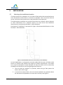
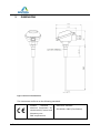
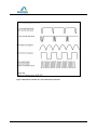
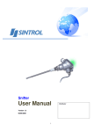
Sintrol Snifter A1+ Manual Version 1.2.2 Table of Contents 1 INTRODUCTION ......................................................................................... 3 1.1 Safety ............................................................................................................. 3 1.2 Product overview ........................................................................................... 3 1.3 How does it work? ......................................................................................... 3 2 INSTALLATION ........................................................................................... 4 2.1 Selecting the installation location.................................................................. 4 2.2 Installing the sensor ....................................................................................... 5 3 WIRING ..................................................................................................... 6 4 TECHNICAL SPECIFICATION......................................................................... 7 5 DIMENSIONS ............................................................................................. 9 6 OPERATION ..............................................................................................10 6.1 The alarm threshold factory setting values: ................................................ 10 7 AUTO-SETUP .............................................................................................12 7.1 How to do the auto-setup? .......................................................................... 12 8 MAINTENANCE .........................................................................................13 9 TROUBLESHOOTING ..................................................................................13 9.1 No output signal ........................................................................................... 13 9.2 No response after auto-setup ...................................................................... 13 9.3 Boot check.................................................................................................... 13 Snifter A1+ User Manual 2 1 INTRODUCTION This manual describes how to install and use SINTROL’s Snifter A1+ dust monitor. Sintrol shall not be liable for any loss or damage whatsoever arising from use of any information or details therein, or omission or error in this manual, or any misuse of the product. 1.1 Safety Snifter A1+ requires 12 - 24 VDC power supply. Although these voltage levels are considered safe, the process gas or dust particulates can be hazardous to health. Take appropriate precautions when installing the monitor: Unless the process conditions are known to be entirely safe, suitable precautions must be taken before any entry is made into the duct for installation or maintenance purposes. 1.2 The unit may be installed in ducting, containing particulate, hazardous to health. The particulate may be inflammable, explosive or toxic The gas can be hot and pressurised Product overview The Snifter A1+ Dust monitor is a microprocessor-based, self-adjusting device, equipped with two fixed output signal and backlit illuminated front cover. Device is designed for filter bag leak detection. It is a compact unit with the sensor and control electronics built into one IP65 enclosure, which has been specifically designed for easy installation and operation. 1.3 How does it work? The Snifter A1+ uses Sintrol’s proven and reliable inductive electrification technology where the interaction of particles with the sensor rod causes a small electrical charge to pass between the particulate and sensor. It is this small electric charge that provides the signal monitored by the electronics, the signal generated is proportional to the dust level even if particles accumulate on the sensor. Experience has shown that this method of monitoring dust level in gasses, offers accurate results with minimum maintenance. Snifter A1+ User Manual 3 2 INSTALLATION 2.1 Selecting the installation location The best location for installation is in a section of duct where the particulate has an even distribution and the flow is as laminar as possible. This is to ensure that the sensor rod comes into contact with a representative flow of particles. The ideal position would be in a section of duct that has no bends, valves, dampers or other obstructions for a distance equal to at least three duct diameters downstream or upstream (preferable 5 x duct diameter). Description of installation is presented in Figure 1 Recommended distance to duct bends (D = Duct diameter). Figure 1 Recommended distance to duct bends (D = Duct diameter) In some applications, a compromise must be made and the sensor will have to be fitted in a position that satisfies the majority of above requirements. The Snifter A1+ must be attached to metal ductwork so that the device will be electrically shielded from interference and has good ground reference. 1. The unit shall be installed in a position, where the gas flow passes the sensor rod in a 90 angle. 2. In round cross-section ducts, the unit can be installed in any position above the horizontal axis (between 9 o’clock and 3 o’clock). See Figure 2 Snifter A1+ User Manual 4 3. For square cross-section ducts, the unit must be positioned in the middle of the top or in the middle of one of the sides. See Figure 3 4. Although the sensor is not affected by vibration, very high vibration levels should be avoided. 5. The units must not be installed in direct sunlight or in areas where the ambient temperature is above +40 °C. The unit above The mounting socket in the middle of the side or horizontal axis in the middle of the top Figure 2 Round cross section duct Figure 3 Square cross section duct NOTE The sensor must not contact the opposite wall or any other obstacle inside the duct. The only allowed interaction with sensor is dust particles. 2.2 Installing the sensor Once the location of the unit has been selected, the Snifter A1+ with NPT 1/2” male thread can be installed to process with 1/2” female thread. Make sure the installation is in the right position, insert the sensor inside the adapter and rotate the Snifter until the connection is tight. NOTE Do not over tighten the Snifter A1+ with process connection - It may cause damage to sensor and electronics. Snifter A1+ User Manual 5 3 WIRING The Snifter A1+ comes with two meter power and signal cable. There are 5 wires, two wires for VDC power source, two for alarm signals, and one for automatic setup signal. Connect the VDC power supply to pink (+) and GND to gray (-) wires. Blue and red wires are for alarm signals and they give the same voltage levels as power input voltage, when the alarm latches to high state. Wire colour Signal name BLUE Alarm signal 1 RED Alarm signal 2 GRAY V- (GND) PINK V+ (VDC) GREEN Auto-setup Table 1 Wiring and signals Snifter A1+ User Manual 6 4 TECHNICAL SPECIFICATION Product name Snifter A1+ Measurement Objects Solid particles in a gas flow Particle Size 0.3 µm or larger Measurement Range From 0.1 mg/m³ Measurement Principle Inductive Electrification Protection Category IP65 Sensor Length (total/measuring) 250 mm / 185 mm Power Supply 12-24 VDC Power Consumption 3W Cable Connection 2 meter cable, 5 wires Process Connection NPT 1/2" male thread Output Signals Alarm settings Two output signals (100 – 280 mA) Back light illuminated front cover Set automatically by auto-setup based on average measured dust flow: 5 times and 20 times of reference dust flow. Process Conditions Temperature Max 250 °C Pressure Max 200 kPa Gas Velocity Min 3 m/s Humidity Max 95 % RH (non-condensing) Ambient Conditions Temperature -20...+40 °C Humidity Max 95 % RH (non-condensing) Snifter A1+ User Manual 7 Materials and Weight Probe (wetted part) Stainless steel (AISI 316L) Process Connection (wetted part) Stainless steel (AISI 316L) Enclosure Aluminum Probe Insulation (wetted part) PEEK Weight 0.6 kg Table 2 Technical specification Snifter A1+ User Manual 8 5 DIMENSIONS Figure 4 Structure and dimensions This instrument conforms to the following standards Product standard electrical equipment for measurement, control and laboratory use – Reference standard IEC 61326-1:2005 (First Edition) EMC requirements Snifter A1+ User Manual 9 6 OPERATION The Snifter A1+ Dust Monitor measures the dust level in a gas flow by using inductive electrification technology which is based on AC measurement of moving particles which carry a charge. There are two alarm signal outputs to indicate two different alarm conditions. In addition to this, the front cover illumination will blink to inform about the current alarm condition. 6.1 The alarm threshold factory setting values: Alert: > 5 times normal dust level (during automatic setup) Alarm: > 20 times normal dust level (during automatic setup) ALARM SIGNALS DUST LEVEL - S2: LOW S2: HIGH S1: HIGH S2: LOW S1: HIGH S2: HIGH OPERATION Power OFF, S1: LOW S1: LOW FRONT COVER ILLUMINATION Dust level < Limit1 OFF failure failed ON Normal operation or auto-setup BLINKING Limit1 <= Dust level < Limit2 COUNT Alert IS ONE (B) BLINKING Dust level >= Limit 2 COUNT Alarm IS TWO (C) Table 3 Default operating configuration on factory settings Snifter A1+ User Manual 10 Figure 5 Description of Snifter A1+ cover illumination sequences. Snifter A1+ User Manual 11 7 AUTO-SETUP To be able to detect variations in dust follow, and to set the alarm so that it will go off if there is excessive dost flow, you must determine the typical dust flow in the application when the process is operating normally. The unit has an auto-setup function. With this, you can set the measuring range of the dust monitor. Before running the auto-setup it is necessary to know that the process is running with normal dust flow. When initiated, auto-setup sets the dust measuring parameters based on the normal dust flow. After the auto-setup the alarm signals are set as follows: 7.1 • alert when the dust concentration exceeds 5 times the typical dust level. • alarm when the dust concentration exceeds 20 times typical dust level. How to do the auto-setup? Follow the procedure below to run the auto-setup. 1. Connect the sensor to the duct, connect the power to the device and wait for 10 minutes the process to stabilize. 2. Then start the auto-setup procedure by connecting the automatic setup signal (green wire) to the V+ signal (wire) for a period of 1 second. The automatic setup will initiate and the front panel light will start to blink slowly (sequence D in Figure 5 Description of Snifter A1+ cover illumination sequences.). 3. Then Release the automatic setup signal, by disconnecting the green wire from V+. Auto-setup procedure takes 1000 seconds (approx. 17 min) to complete. When the front cover lighting stops blinking, the auto-setup is finished and the Snifter A1+ is ready for use. Snifter A1+ User Manual 12 8 MAINTENANCE Snifter A1+ dust monitor needs very little or practically no maintenance. We recommend checking the status of the sensor after the first 2 months of operation. If no notable build-up of contamination can be observed, the recommended maintenance interval is 2 years. However, if the particles in the gas are sticky and tend to build up, the cleaning needs to be done more often. The need for maintenance depends on the process. The maintenance is done by removing the unit from the process and cleaning the sensor rod to prevent signal leakage to ground. Opening the enclosure during the maintenance is unnecessary and will terminate the warranty. 9 TROUBLESHOOTING 9.1 No output signal Check the power and signal wiring are connected correctly. Check that there is power on (cover glows). Do the auto-setup If the monitor is not giving any output signal after these checks, contact your local distributor. 9.2 No response after auto-setup Check that there is normal process going on during auto-setup. Check that the power and signal wiring are connected correctly. Check that the signal is not leaking to ground. o There is NO contact between metal sensor probe and duct wall. o Ensure that the gas is not condensing (causes signal leakage). o Check that the sticky dust does not build up on the base of the sensor and no bridging between sensor probe and duct wall. NOTE Front cover illumination sequence F is on (10 Hz rate), when signal leaking to the ground is permanent. 9.3 Boot check If green wire for starting automatic setup is connected before 15 seconds has elapsed from the power ON, boot check is initiated. Test takes some seconds and it is indicated with a sharply blinking front cover illumination sequence E (1 Hz rate). Snifter A1+ User Manual 13 If test fails, sequence F is initiated (10 Hz rate). Snifter A1+ User Manual 14 NOTES Snifter A1+ User Manual 15 SINTROL Oy Ruosilantie 15 00390 Helsinki Finland Tel +358 9 5617 360 Fax +358 9 5617 3680 www.sintrolproducts.com Snifter A1+ User Manual 16