1
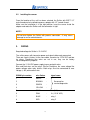
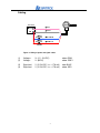
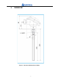
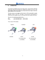
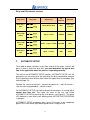
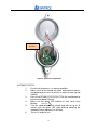
Snifter
User Manual
Version 1.3
08/09/2009
1
Distributor
Table of Contents
1.
INTRODUCTION ................................................................................... 3
1.1
Safety ................................................................................................ 3
1.2
Product overview ............................................................................... 3
1.3
How does it work? ............................................................................. 3
2.
INSTALLATION .................................................................................... 4
2.1
Selecting the installation location ....................................................... 4
2.2
Installing the sensor ........................................................................... 6
3.
WIRING ................................................................................................. 6
4.
TECHNICAL SPECIFICATION ............................................................. 8
5.
DIMENSIONS ....................................................................................... 9
6.
OPERATION ....................................................................................... 10
7.
AUTOMATIC SETUP .......................................................................... 11
8.
MAINTENANCE .................................................................................. 13
9.
TROUBLESHOOTING ........................................................................ 13
9.1.
The Monitor is not giving relay output signal.................................... 13
9.2.
The Monitor is not responsing after autosetup procedure................ 13
NOTES .......................................................................................................... 14
2
1.
INTRODUCTION
This manual describes how to install and use SINTROL’s triboelectric dust
monitor Snifter. Sintrol shall not be liable for any loss or damage whatsoever
arising from use of any information or details therein, or omission or error in
this manual, or any misuse of the product.
1.1
Safety
Snifter requires 12- 24 VDC power supply. Although 12-24VDC voltage level is
considered safe, but the process gas or dust particulates can be hazardous to
health.
Take appropriate precautions when installing the monitor:
Unless the process conditions are known to be entirely safe,
suitable precautions must be taken before any entry is made into
the duct for installation or maintenance purposes.
•
•
•
The unit may be installed in ducting, containing particulate, hazardous to
health.
The particulate may be inflammable, explosive or toxic
The gas can be hot and pressurised
1.2 Product overview
The Snifter Dust monitor is a microprocessor-based, self-adjusting device,
equipped with two alarm relays and indication LED in front cover.
The Snifter is designed for filter bag leak detection. It can also be used to
detect blockage or stoppage in pneumatic transport and bulk solids handling. It
is a compact unit with the sensor and control electronics built into one IP65
enclosure, which has been specifically designed for easy installation and
operation. The Snifter is designed for applications at up to 2 bar and 140 °C.
1.3 How does it work?
The Snifter uses proven and reliable triboelectric technology where the
interaction of particles with the sensor rod causes a small electrical charge to
pass between the particulate and sensor.
It is this small electric charge that provides the signal monitored by the
electronics, the signal generated is proportional to the dust level even if
particles accumulate on the sensor. Experience has shown that this method of
monitoring dust level in gasses, offers accurate results with minimum
maintenance.
3
2.
2.1
INSTALLATION
Selecting the installation location
The best location for installation of the units of the Snifter is in a section of duct
where the particulate has an even distribution and the flow is as laminar as
possible. This is to ensure that the sensor rod comes into contact with a
representative flow of particles.
The ideal position would be in a section of duct that has no bends, valves,
dampers or other obstructions for a distance equal to at least three duct
diameters downstream or upstream (preferable 5 x duct diameter). See figure
1.
Figure 1. Recommended distances to duct bends (DN=Duct Diameter)
In some applications, a compromise must be made and the sensor will have to
be fitted in a position that satisfies the majority of above requirements. The
Snifter must be attached to metal ductwork so that they will be electrically
shielded from interference and be provided with a ground reference.
1. The unit shall be installed in a position, where the gas flow passes the
sensor rod in a 90° angle.
2. In round cross-section ducts, the unit can be installed in any position
above the horizontal axis (between 9 o’clock and 3 o’clock). See figure
2a.
3. For square cross-section ducts, the unit must be positioned in the
middle of the top or in the middle of one of the sides. See figure 2b.
4. Although the sensor is not affected by vibration, very high vibration
levels should be avoided.
5. The units must not be installed in direct sunlight or in areas where the
ambient temperature is above 60 °C.
4
The mounting socket in
the middle of the side or
in the middle of the top
The unit above
horizontal axis
Figure 2a. Round cross-section duct
Figure 3.
Figure 2b. Square cross-section duct
Snifter installed on a duct
NOTE !
The sensor must not contact the opposite wall or any other obstacle
inside the duct. The only allowed interaction with sensor is dust particles.
5
2.2
Installing the sensor
Once the location of the unit has been selected, the Snifter with BSPT 1/2”
male thread can be installed to process adapter with 1/2” female thread.
Make sure the installation is in the right position, insert the sensor inside the
adapter and rotate the Snifter until the connection is tight.
NOTE !
Do not over tighten the Snifter with process connection - It may cause
damage to sensor and electronics.
3.
WIRING
Required voltage for Snifter is 12-24 VDC
The snifter comes with two meter power and signal cable ready connected.
There are 4 pairs (8 wires) in the same cable, two wires for 12-24 VDC and two
for relays. Remaining four wires are not in use, they are for factory
service/diagnostics purposes.
Connect the 12-24 VDC power supply to grey and pink wires.
Blue and Red wires are for relays. Blue or Red gives the same voltage like
power voltage when relay latches. Both relays must be connected to zero
voltage (= 0V) with another wire.
CONN1 pin number
wire Colour
1
WHITE
-
2
BROWN
-
3
GREEN
-
4
YELLOW
-
5
GREY
-
V- (0 V)
6
PINK
-
V+ (12-24 VDC)
7
BLUE
-
relay 1
8
RED
-
relay 2
6
signal name
Reserved for
service/diagnostics
Cabling
Figure 4. Wiring of power and signal cables
(1)
(2)
Voltage +
Voltage -
V+ (12 - 24 VDC)
V- (0VDC)
colour PINK
colour GREY
(3)
(4)
Signal out
Signal out
V (12-24 VDC, Imax = 170 mA)
V (12-24 VDC, Imax = 170 mA)
color BLUE
colour RED
7
4.
TECHNICAL SPECIFICATION
Snifter specifications
Measurement objects
Solid particles in a gas flow
Particle size
0,3 µm or larger
Measurement range
from 0,1 mg/m3
Temperature
max 140 °C
Pressure
2 bar
Gas velocity
Min. 4 m/s
Humidity
95% RH (non-condensing)
Measurement principle
Damping time
Output signals
Alarm settings
Triboelectric
(electrostatic/-dynamic detection)
1-300 seconds (predefined)
2 solid state relays
(170mA and 200mA )
Alert -
5 x normal dust level
Alarm - 20 x normal dust level
Ambient temperature
- 20 – + 60 °C
Probe
SS316 L (220 mm)
Enclosure
Aluminium
Protection category
IP65
Power supply
12-24 VDC
Power consumption
3W
Cable (power + signal)
2 meter 4 pair cable
Installation
1/2” BSPT
Weight
Approx. 0,7 kg
This instrument conforms to the following standards
Product standard -
Reference standard
electrical equipment for
IEC 61326-1:2005 (First Edition)
measurement, control and
laboratory use –
EMC requirements
8
5.
DIMENSIONS
½ “BSPT
Figure 5. Structure and dimensions of Snifter
9
6.
OPERATION
The Snifter Dust Monitor measures the dust level in a gas flow by monitoring
electrostatic/-dynamic discharge when charged dust particles hit or pass near
by the probe. There are two solid state relay contact alarm outputs and three
colour indicator LED in front cover.
The alarm relays are arranged such that relay 2 is ON (=connected) in normal
operation. Relay 2 turns OFF and relay 1 ON when dust level exceeds 5x
normal dust level and both relays are ON when dust level exceeds 20x normal.
The alarm threshold factory default values:
Alert:
> 5x normal dust level = Limit 1 value
Alarm:
> 20x normal dust level = Limit 2 value
Three state of LED indicator
GREEN
NORMAL
ORANGE
ALERT
dust concentration
> 5x NORMAL
10
RED
ALARM
dust concentration
> 20x NORMAL
Relay and LED indicator functions
relay on/off
relay state
Both relays
OFF
Relay 2 ON
(alone)
Relay 1 ON
(alone)
Both relays
ON
7.
Signal level
led
indicator
Power OFF or fault
OFF
Signal < Limit1
GREEN
Normal
Limit1 < signal < Limit2
YELLOW
Alert
signal > Limit 2
RED
Alarm
operation
Power OFF
or failure
AUTOMATIC SETUP
To be able to detect variations in dust flow, and to set the alarm so that it will
go on if there is excessive dust flow, you must determine the typical dust
flow in the application when the process is operating normally.
The unit has an AUTOMATIC SETUP function. AUTOMATIC SETUP sets the
parameters so, the relays gives the alert when the dust concentration exceeds
5x the typical dust level and an alarm when 20x typical level is exceeded. (See
table on page 13)
Connect the sensor to the duct – connect the power on – wait 10 minutes –
start the auto setup procedure – close the cover.
For AUTOMATIC SETUP you need to know that the process is running with a
normal dust flow rate. Then open the cover of the unit, and initiate
AUTOMATIC SETUP by pressing the small button, (see Figure 6). The green
LED indicator in front cover starts blinking when AUTOSETUP PROCEDURE
is going on.
AUTOMATIC SETUP procedure takes up to 10 minutes to be completed,
green LED in front cover stops blinking and Snifter is ready for use.
11
AUTOSETUP
BUTTON
Figure 6. Automatic setup button
AUTOMATIC SETUP
1.
2.
3.
4.
5.
6.
Ensure that the process is in normal conditions.
Make sure that the monitor has been connected to process
and powered for at least 10 minutes in order to warm up and
stabilise!
Press the AUTOMATIC SETUP BUTTON (the small button on
printed circuit board) Figure 6.
Make sure that green LED indicator in front cover starts
NEXT PAGE
blinking.
Turn the cover of enclosure closed and wait for up to 10
minutes until the green LED stops blinking indicating the
Automatic Setup sequence has finished.
The unit is ready for use.
12
8.
MAINTENANCE
Snifter Dust Monitor needs very little maintenance. To achieve maximum
reliable operation the recommended maintenance interval is 2 months.
Maintenance is done by removing the unit from the process and cleaning the
sensor rod to prevent signal leakage to ground.
If the particles in the gas are sticky and tend to build up, the cleaning needs to
be done more often.
Check the PC board is firmly connected inside the enclosure. Check LED
indicator cable and signal/power cable connectors are connected correctly.
9.
TROUBLESHOOTING
9.1.
1.
2.
3.
The Monitor is not giving relay output signal
Check the power and signal wiring are connected correctly.
Check there is power on (cover LED glows).
Do the auto setup procedure
(green LED starts blinking – stops when ready).
If the monitor is not giving any relay output signal after checks 1, 2 and
3 contact your local distributor.
9.2.
1.
2.
3.
The Monitor is not responsing after autosetup procedure
Check that there is normal process going on and there were
normal operation conditions during auto setup.
Check the power and signal wiring are connected correctly.
Check the signal is not leaking to ground.
- There is NO contact between metal sensor probe and duct wall.
- Ensure the gas is not condensing (causes signal leakage)
- Check the sticky dust does not build up on the base of the
sensor and no bridging between sensor probe and duct wall.
13
NOTES
______
______
______
_________________________________________________________________
14
Sintrol Oy
Ruosilantie 15
FI 00390 Finland
Tel. +358 9 5617 360
Fax +358 9 5617 3680
15