1
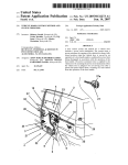
2
INDEX
1 Characteristics................................................................................................................4
2 What the Kit Includes .....................................................................................................5
3 How to Choose the Heat Exchanger .............................................................................5
4 Functional Scheme and Probes Position .....................................................................7
4.1 (8-10) HP .......................................................................................................................7
4.2 (13-16) HP .....................................................................................................................8
4.3 (20-25) HP .....................................................................................................................9
5 AHU Kit Control Method...............................................................................................11
5.1 Fresh Air Only ..............................................................................................................11
5.2 Room Air Recycle and Adjustable Fresh Air Ratio.......................................................14
6 Electrical Connections .................................................................................................15
6.1 (8-10) HP .....................................................................................................................15
6.2 (13-16) HP ...................................................................................................................16
6.3 (20-25) HP ...................................................................................................................18
7 Electrical Diagram ........................................................................................................20
7.1 (8-10) HP .....................................................................................................................20
7.2 (13-16) HP ...................................................................................................................21
7.3 (20-25) HP ...................................................................................................................24
8 Dimensions Kit Components.......................................................................................27
9 Wiring Example of AHU Control System ....................................................................29
10 Switch Setting .............................................................................................................31
11 Optional .......................................................................................................................34
11.1 Analogue Temperature Setting Converter CS31 .......................................................34
11.2 Soft Starter................................................................................................................34
12 Frequently Asked Questions .....................................................................................35
13 Applications ................................................................................................................36
3
1. Characteristics
8 HP Kit
Nominal Cooling Capacity: 22.4 kW
Nominal Heating Capacity: 25.0 kW
Maximum Heating Capacity: 26.5 kW
On-Off Fan Speed Control
10 HP Kit
Nominal Cooling Capacity: 28.0 kW
Nominal Heating Capacity: 31.5 kW
Maximum Heating Capacity: 33.5 kW
On-Off Fan Speed Control
13 HP Kit
Nominal Cooling Capacity: 35.5 kW
Nominal Heating Capacity: 40.0 kW
Maximum Heating Capacity: 42.5 kW
On-Off Fan Speed Control
16 HP Kit
Nominal Cooling Capacity: 45.0 kW
Nominal Heating Capacity: 50.0 kW
Maximum Heating Capacity: 53.0 kW
On-Off Fan Speed Control
20 HP kit
Nominal Cooling Capacity: 56.0 kW
Nominal Heating Capacity: 63.0 kW
Maximum Heating Capacity: 67.0 kW
On-Off Fan Speed Control
25 HP kit
Nominal Cooling Capacity: 71.0 kW
Nominal Heating Capacity: 80.0 kW
Maximum Heating Capacity: 84.0 kW
On-Off Fan Speed Control
4
2. What the kit Includes
The Kit is made up by:
(8-10) HP
- Control Box: It includes the boards to control the expansion valves and to control the
AHU fan (with Fan Soft Starter Controller if required);
- 1 Electronic Expansion Valves Assembly (strainers are just installed);
- Probes and Capacity Adapter.
(13-16) HP
- Control Box: It includes the boards to control the expansion valves and to control the
AHU fan (with Fan Soft Starter Controller if required);
- 3 Electronic expansion valves;
- 6 Strainers to protect the valves;
- Copper Branches Set to joint the refrigerant components.
(20-25) HP
- Control Box: It includes the boards to control the expansion valves and to control the
AHU fan (with Fan Soft Starter Controller if required);
- 3 Electronic expansion valves;
- 6 Strainers to protect the valves;
- Copper Branches Set to joint the refrigerant components.
3. How to Choose the Heat Exchanger
8 HP
Permitted volume from 4,6 dm³ to 6,6 dm³
10 HP
Permitted volume from 6,5 dm³ to 8 dm³
Cooling Mode
- Saturated Suction Equivalent Temperature 7°C
- Refrigerant Superheating 5°C
Heating Mode
- Saturated Condensing Equivalent Temperature 45°C
- Refrigerant Supercooling 5°C
13 HP
Permitted volume from 6 dm³ to 8 dm³
16 HP
Permitted volume from 7.5 dm³ to 9 dm³
5
Cooling Mode
- Saturated Suction Equivalent Temperature 7°C
- Refrigerant Superheating 5°C
Heating Mode
- Saturated Condensing Equivalent Temperature 45°C
- Refrigerant Supercooling 5°C
The configuration of the heat exchanger is standard with two pipes. Since the cooling
operation, there is also the distributor of the liquid on the tube.
20HP
Permitted Volume from 9 dm³ to 11 dm³
25 HP
Permitted Volume from 10 dm³ to 13 dm³
Cooling Mode
- Saturated Suction Equivalent Temperature 7°C
- Refrigerant Superheating 5°C
Heating Mode
- Saturated Condensing Equivalent Temperature 45°C
- Refrigerant Supercooling 5°C
The heat exchanger is divided in two parts. The first part is design for the 2/3 of capacity
the second one for the remaining part. The air goes through the bigger part then crosses
the smaller part (see the figure below).
6
4. Functional Scheme e Probes Position
4.1 (8-10) HP
The AHU (8-10) HP Kit requires a standard refrigerant circuit with a single circuit heat
exchanger, the same used for DX indoor units.
Cooling Mode
The liquid refrigerant reaches the expansion valve through the strainers. It evaporates in
the heat exchanger and then, as vapour, comes back to the GHP.
Heating Mode
The vapour reaches the heat exchanger, here it condensates and come back to the GHP
through the strainers and the expansion valve.
7
4.2 (13-16) HP
The AHU (13-16) HP requires a standard circuit of the refrigerant gas with
coil in a single circuit, the same type used in direct expansion indoor units.
a heating
Cooling mode
The liquid refrigerant reaches the expansion valve through the filters, evaporated in the
heating coil and then the vapour state, returns to the outdoor unit.
Heating mode
The refrigerant gas to the gas phase reaches the heat exchanger, including condensate
and returns to the outdoor unit through the filters and the expansion valve.
8
4.3 (20-25) HP
Cooling Mode
The liquid refrigerant reaches the three-pipe joint and there is divided. 1/3 of the
refrigerant goes through the strainers and the expansion valve and reaches a small
distributor. The 2/3 goes through the two expansion valves and the small branch joint and
reach the big distributor. After the heat exchanger the refrigerant flows through the big
branch joint to the GHP.
Heating Mode
The refrigerant is split by the big branch joint and then it reaches the heat exchanger. In
liquid form it goes through the distributors, expansion valves and three pipe joints to the
GHP.
9
10
5. AHU Kit Control Method The aim of this document is to provide information about the AHU control method. It also
provides an easy reference to select the proper combination with indoor units.
The AHU kit is designed to be suitable for two types of installation layout.
Fresh air only (all the processed air flow is taken from outside);
Room air recycle and adjustable fresh air ratio (most of the processed air is taken from
inside);
5.1 Fresh Air Only
When this configuration is selected, the AHU works the intake air to the building in series
with a heat recovery unit. This means only part of the overall load is covered by the AHU.
The remaining load is managed by standard indoor units.
In fact, in heating mode the AHU heat exchanger capacity varies with the air intake
temperature and precisely it drops when the intake temperature increases. On the
contrary, the capacity of the indoor units is quite constant (see graph 1).
As a consequence of selecting this configuration, the AHU cannot control the air discharge
temperature. Therefore, the provided capacity depends only on the size of the heat
exchanger. It is possible to manage the room temperature by controlling the indoor units,
which can vary their capacity by adjusting the room set temperature.
In case of high outdoor temperatures, it is anyway possible to switch the AHU to fan mode
and let the indoor units manage the room temperature (See graph 2).
11
The AHU kit is not designed to be the only unit to control room temperatures. It is always
necessary to install indoor units. In fact, in case the AHU is the only heating device, when
delivered capacity is higher than the building need, problems in temperature management
occur. The following example shows that when room temperatures exceed T1, room
overheating, discomfort and consequently excessive gas consumption occur.
12
In cooling mode the control method is the same but the heat exchanger capacity increases
with outdoor temperature.
13
5.2 Room Air Recycle and Adjustable Fresh Air Ratio
When this configuration is selected, it is only necessary to verify the nominal capacity at
rated conditions, which are given in the project. The AHU kit modulates the delivered
capacity to ensure comfort temperatures. This delivered capacity drops to zero when the
set temperature is reached. Generally speaking, designers always keep the fresh air ratio
within the range of 0 and 30 %.
14
6. Electrical Connections
6.1 (8-10 ) HP
Here under the control box terminal block.
L-N: AHU Power Supply
From Y1 to Y6: Electronic Expansion Valve
R3-R4: Gas Pipe Temperature Sensor
R1-R2: Liquid Pipe Temperature Sensor
R5-R6: Intake Air Temperature Sensor
P1-P2: Remote Controller
F1-F2: Bus Line (to GHP)
T1-T2: Digital Input On-Off Control
C1-C2: Fan Control (Maximum 230V – maximum 2 A)
Note:
A special harness to joint the wires from Y1 to Y6 is just
included in the Electronic Expansion Valves Assembly Box.
Input-Output Board contacts
A+ A-: Temperature Setting Analogue Input (see Switch setting chapter)
BC-B1-B2: Control Digital Input (see Switch setting chapter)
W1-W2: Operation Digital Output (free contact)
W3-W4: Error Display Output (free contact)
15
6.2 (13-16) HP
Here under the terminal block is divided in order to show better the connection labels.
Notes:
Explanations in RED are for electrical contacts made during the AHU construction.
Explanations in BLUE are for optional contacts.
Explanations in GREEN are for contacts made during the AHU installation
The Expansion Valves connection is made using special harnesses, included in the kit, in
order to avoid wrong wiring
X13A : Intake Air Temperature Sensor
X12A : Higher Contacts : Liquid Pipe Temperature Sensor
X14A : Discharged Air Temperature Sensor
X11A : Higher Contacts : Gas Pipe Temperature Sensor
P1-P2 : Optional Second Remote Controller
F1-F2 : Bus Line (To GHP)
T1-T2 : OnOff or Forced Off Contact
X7A-1 : Expansion Valves Controller
16
B1B2BC : Digital Input
A+A- : Temperature Setting Analogue Input
GND-MP-MP-MP Fan Motor Power Supply (three phase)
GND-LR-LS-LT-LN AHU Power Supply
GND-MP-MP Fan Motor Power Supply (single phase)
These are the X7A Connector (already wired in
the electrical box)
T2A-N2 : Soft Starter Power Supply
The electrical box can be equipped with a soft starter device. It
permits to give power to the fan kindly, avoiding overpressure in the
duct
17
6.3 (20-25) HP
Here under the terminal block is divided in order to show better the connection labels.
Notes:
Explanations in RED are for electrical contacts made during the AHU construction.
Explanations in BLUE are for optional contacts.
Explanations in GREEN are for contacts made during the AHU installation
The Expansion Valves connection is made using special harnesses, included in the kit, in
order to avoid wrong wiring
X13A : Intake Air Temperature Sensor
X12A : Higher Contacts : Liquid Pipe Temperature Sensor (Big Heat Exchanger Part)
X12A : Lower Contacts : Liquid Pipe Temperature Sensor (Small Heat Exchanger Part)
X14A : Discharged Air Temperature Sensor
X11A : Higher Contacts : Gas Pipe Temperature Sensor (Big Heat Exchanger Part)
X11A : Lower Contacts : Gas Pipe Temperature Sensor (Small Heat Exchanger Part)
P1-P2 : Optional Second Remote Controller
F1-F2 : Bus Line (To GHP)
T1-T2 : OnOff or Forced Off Contact
X7A-1 : Expansion Valves Controller (Big Heat Exchanger Part)
18
X7A : Expansion Valve Controller (Small Heat Exchanger Part)
B1B2BC : Digital Input
A+A- : Temperature Setting Analogue Input
GND-MP-MP-MP Fan Motor Power Supply
GND-LR-LS-LT-LN AHU Power Supply
These are the X7A Connector (already wired in
the electrical box)
T2A-N2 : Soft Starter Power Supply
The electrical box can be equipped with a soft starter device. It
permits to give power to the fan kindly, avoiding overpressure in the
duct
19
7. Electrical Diagram
7.1 (8-10) HP
20
7.2 (13-16) HP
Sheet 1
21
Sheet 2
22
Sheet 3
23
7.3 (20-25) HP
Sheet 1
24
Sheet 2
25
Sheet 3
26
8. Dimensions Kit Components
Attached the AHU Kit Components dimensions
Copper Branches kit AHU (20-25) HP
Copper Branches kit AHU (13-16) HP
27
Electrical Box
Electrical box dimensions: 65cm x 42cm x 20 cm (The cover is not shown) (*)
(*) For AHU (25-20-16-13) HP
Strainers
Each strainer is 13cm long
-
N°6 for AHU (25-20) HP
-
N°4 for AHU (16-13) HP
Expansion valves
Each expansion valves is provided with two copper pipe 5cm long
-
N°3 for AHU (25-20) HP
-
N°2 for AHU (16-13) HP
28
9. Wiring Example Of AHU Control System
AHU can be managed by:
‐
Standard Remote or Central Controller according with the attached AISIN and
DAIKIN user manual. If a further remote controller is installed remember to set it
“slave”
‐
BMS Digital And Analogue Input according with the follow chapter “Switch setting”
‐
Forced OFF Digital Input (T1T2)
29
If is installed an I-Touch centralized control, add the card DTA109A51
30
10. Switch Setting
The EC9432 (D) board is installed in electrical box upper part, under the AISIN remote
controller. You need to remove it from the DIN bar before making any operation.
Default setting:
SS1 – NON VOLT
SS2 – POSSIBLE
RS1 – POSITION 0
A+A- Temperature Setting Input
To enable the temperature setting from remote controller and from the contact A+A- set
the SS2 Switch to POSSIBLE. IMPOSSIBLE setting don’t permit to use the remote
controller for temperature setting. For any reason is not permitted to apply voltage to the
A+A- terminal block.
The relationship between setting temperatures and resistance value is shown in the table
Set
16
17
18
19
20
21
22
23
24
Temp
0
5
13,8 22,4
31,0
39,4
48,2
56,6
65,2
Ohm ÷
÷
÷
÷
÷
÷
÷
÷
÷
3,4
11,6 20,0 28,4
36,4
44,8
52,8
61,2
69,4
Set
25
Temp
73,8
Ohm ÷
77,8
26
27
28
29
30
31
32
82,4 91,0 99,4
108,6 117,2 125,8 134,2
÷
÷
÷
÷
÷
÷
÷
85,8 94,0 102,2 110,4 119,2 127,4 140,0
31
B1B2Bc Input
Input With Voltage
Set the switch SS1 to VOLT and use 12-24 V
Direct Current. No polarity
Input With No Voltage
Set the switch SS1 to NON VOLT and use a
vinyl sheathed cable of 0.18 mm² or more.
The total length should be less than 150 m
Setting Of Control Mode Rotary Switch RS1
Functions description:
Remote Control Rejection : You can turn ON/OFF only by central controller
Remote Controller OFF Only Accepted : You can turn ON/OFF by central controller, you
can turn only OFF from remote controller
Central Priority : You can turn ON only by central controller and from remote controller only
during the set time
Individual Priority : You can turn ON/OFF by both central controller and remote controller
Remote Controller Permission Timer : You can turn ON/OFF by remote controller during
set time.
32
RS1
Position
Functions
0
Input Ignored
1
Remote Control Rejection
2
Central Priority
3
Remote Control
Acceptance/Rejection
4
Remote Control
Acceptance/Rejection, OFF
5
Remote Control Rejection
6
Last Command Priority
7
Remote Control Rejection
8
Last Command Priority
9
Remote Control OFF
Acceptance
A
Remote Control
Acceptance/Rejection, OFF
B
Last Command Priority
C
D
E
F
Position 5 + Energy Saving
Control
Position 5 + Temperature
Set Back
Position 6 + Energy Saving
Control
Position 6 + Temperature
Set Back
Description Of Operation
Input Between
B1 - Bc
-
Input Between
B2 - Bc
-
Start at ON, Stop at Off
Start at ON (remote control
acceptance)
Stop at OFF (remote
control rejection)
Stop at ON (remote control
The same as position 1
rejection), input B1 – Bc
(only stop is accepted by
acceptance at OFF
remote controller)
Start at ON (remote control
acceptance)
Stop at OFF (remote
control rejection)
Start/Stop (Repeats)
The same as position 5
Stop at ON (remote control
acceptance) Start at OFF
(remote control rejection)
Start at ON
Stop at ON
Start at ON (remote control Stop at ON (remote control
acceptance)
rejection)
The same as position 7
(only stop is accepted by The same as position 7
remote controller)
Start at ON (remote control Stop at ON (remote control
acceptance)
rejection)
The same as position 7
(remote
control The same as position 7
acceptance)
Forced thermostat OFF at ON
The same as position 5
Setting
temperature
command at ON
shift
Forced thermostat OFF at ON
The same as position 6
Setting
temperature
command at ON
shift
NOTE: When constant input is used for input B2Bc at position 7 ÷ A, the system is shut-down forcibly (input
B1Bc ignored)
33
11. Optional
11.1 Analogue Temperature Setting Converter CS31
This optional board permits to control the AHU temperature setting using 0-10 VDC
analogue input according to the table below
Set
16
17
18
19
20
21
22
23
24
Temp
Volt 0,85 1,71 2,52 3,33 4,02 4,71 5,32 5,92 6,49
Set
25
26
27
28
29
30
31
32
Temp
Volt 7,00 7,49 7,94 8,34 8,76 9,18 9,54 10
Electrical Connection
5-6 : Board Power Supply 24 Vac (Max 5VA)
1-2 : 0-10 VDC Analogue Input
3-4 : Ohm Analogue Output (It has to be connected to A+ A- terminal block in the EC9432
(D) board )
Note:
The green led indicates that the board is power supplied
11.2 Soft Starter
This optional is a compact fan motor controller that permits you to avoid overpressure in
duct systems. It works reducing the initial motor torque and increasing it step by step till
nominal value. We recommended with fabric duct or when noise reduction during the fan
initial operation is required.
34
12. Frequently Asked Questions
- Where is it used?
The DX AHU is the best solution where there is the need to supply heating and cooling
capacity to open spaces like warehouses, sport arenas and commercial building.
-Which are the best advantages of an AHU?
This kind of indoor unit permits to provide a huge capacity in a very easy way, in fact it’s
no more necessary to install the Yoshi AWS and a complete water loop. The installation
costs are strongly reduced and the technical rooms disappear. Besides the DX technology
guarantees the highest efficiency.
- Which are the disadvantages of an AHU?
The only disadvantage of an DX AHU is related to its control. In fact in all the applications
where the humidity ratio control is required, the water system are the only solution.
(Data and information contained in this booklet are valid for direct expansion installations
and are subject to changes without prior notice)
35
13. Applications
San Giovanni In Persiceto (Bologna) Italy
This system is made up by n°8 GHP 25 HP, each of
them is connected to one AHU
Customer Advantages:
‐ Installation cost is very low
‐ Installation spaces are strongly reduced
‐ There are no dead time to provide capacity
‐ The running costs are lower than a traditional
water plant ( GUE is higher and there is no
pump energy consumption )
36
NOTES
37
38
39
40