1
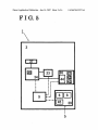
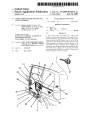
US 20070132273A1
(19) United States
(12) Patent Application Publication (10) Pub. No.: US 2007/0132273 A1
(43) Pub. Date:
Suzuki et al.
(54)
VEHICLE DOOR CONTROL METHOD AND
(30)
Jun. 14, 2007
Foreign Application Priority Data
SYSTEM THEREFOR
Dec. 14, 2005
(75) Inventors: Shintaro Suzuki, Kasugai-shi (JP);
Toshio Machida, Toyota-shi (JP); Eiji
Itami, Chiryu-shi (JP); Mizuho
Morimitsu, Kariya-shi (JP)
Correspondence Address:
(JP) .................................... .. 2005-360353
Publication Classi?cation
(51)
Int. Cl.
B60] 5/06
(52)
Us. or. ............................................................ ..296/155
(57)
(2006.01)
ABSTRACT
BUCHANAN, INGERSOLL & ROONEY PC
POST OFFICE BOX 1404
A door control system and method for a vehicle door
ALEXANDRIA, VA 22313-1404 (US)
poWer assistance for opening of the vehicle door from a fully
closed position When the vehicle door is moved by an
(73) Assignees: AISIN SEIKI KABUSHIKI KAIsHA,
Kariya-shi (JP); TOYOTA SHATAI
KABUSHIKI KAIsHA, Kariya-shi (JP)
(21) Appl. No.:
11/635,629
(22) Filed:
Dec. 8, 2006
37
34 ‘
26
35
3
21
includes a poWer assist mechanism. The system starts a
operation of a door handle under a condition that a door lock
being disengaged in association With the operation of the
door handle. The poWer assistance force is supplied to the
vehicle door by actuating the poWer assist mechanism When
the vehicle door is judged to be not moving even after a
preset time period lapsed from a counting of a time started
from the operation of the door handle.
Patent Application Publication Jun. 14, 2007 Sheet 1 0f 6
FIG.1
US 2007/0132273 A1
Patent Application Publication Jun. 14, 2007 Sheet 2 0f 6
FIG.2
US 2007/0132273 A1
Patent Application Publication Jun. 14, 2007 Sheet 3 0f 6
FIGQ3
US 2007/0132273 A1
Patent Application Publication Jun. 14, 2007 Sheet 4 of 6
US 2007/0132273 A1
FIG.4
19
22
Skid c‘ontrol
computer
21 -
Vehicle
18
speed
signal
Open/Close
signal
Power source
System ON/OFF signal
6
Motor power
23
source
33
’ ON/OFF signal
32
C
E U
Slidedoor
‘ open/close signal
ON/OFF signal
Detecting switch
ON/OFF signal __
. iwFF signal
P-shift position l
ll
ll
9
signal
'
glgéli‘tion
3‘
P_range
Open/Close
Sign“
Jamming detecting signal
'
( F or c l oslng
on l y) 26
\ Body comguter 1
Door control
receiver “\28
27
29
24
Patent Application Publication Jun. 14, 2007 Sheet 5 0f 6
FIG.5
US 2007/0132273 A1
Patent Application Publication Jun. 14, 2007 Sheet 6 0f 6
US 2007/0132273 A1
FIG. 6
s1
Door
82
moving in opening
direction?
(Door lock latch
rotated?)
Handle
operated?
Timer counting
w 84
A preset
time lapsed?
ClutchION
Drive motorION
Door
moving in opening‘
direction?
(Door lock latch
rotated?)
Jamming
$9
4
2
v‘
detected?
Yes
Release ACTION
ClutchION
Drive motorION
door ful Iy closed
V
l Door ful ly closed W810
Yes
812
Reverse movement
Jun. 14, 2007
US 2007/0132273 A1
VEHICLE DOOR CONTROL METHOD AND
SYSTEM THEREFOR
the conventional problems. For example, in the remote
control poWer assist system using a sWitch provided near the
CROSS REFERENCE TO RELATED
APPLICATION
operation, the folloWing improvements have been proposed.
[0001] This application is based on and claims priority
under 35 U.S.C. §ll9 With respect to Japanese Patent
Application 2005-360353, ?led on Dec. 14, 2005, the entire
content of Which is incorporated herein by reference.
FIELD OF THE INVENTION
[0002] The present invention is generally directed to a
vehicle door control method and system, and more particu
larly to improvements in a door control method and system
for a door With a poWer assist mechanism utiliZed in an
automobile door, such as a slide door and back door, etc.
driver’s seat or by a Wireless sWitch to achieve poWered
Normally, in this system, When the driver’ s seat sWitch or the
Wireless sWitch is operated, latch releasing actuator is oper
ated to release the engagement of the door lock for door
open/close operation. After the door lock is disengaged, the
poWer assist mechanism is operated to slide or sWing the
door in the opening direction giving a poWer from a poWer
source. Considering this operation mechanism, the inventors
added the similar function to the poWer slide door mecha
nism of user operation by the door handle. In other Words,
When the user operates the door handle for opening purpose,
the latch releasing actuator is operated to automatically
release the lock by an electrical mechanism. Thereafter the
BACKGROUND
[0003]
As an automobile door, such as a slide door, a
poWer assisted slide door has been used, in Which the door
is slidably opened or closed With a poWer assist mechanism.
This door is sometimes called as a poWer slide door (PSD).
In some of such poWer slide doors, a so-called remote
controlled door operation system is installed for poWer
assisted opening and closing of the door by an operation of
a sWitch provided near the driver’s seat or a remote con
trolling by a Wireless sWitch attached to an engine ignition
key or by a user operation (manual operation) of a door
handle on the vehicle door.
[0004] Concerning the remote control operation for open
ing and closing a door by the user operation of the door
handle as mentioned above, according to one knoWn state of
the art, the poWered door operation (poWer assist open/close
operation) is started after the door handle has been manually
operated by the user from the fully opened or closed door
position up to a certain position. One example of this type
is disclosed in a Japanese Patent Publication No. 10-280806
poWer assist mechanism starts its poWered door opening
operation.
[0008] HoWever, in the conventional poWer slide doors or
the poWer slide doors, Which are actually used, generally the
lock disengagement operation is manually performed by
operating the door handle by the user upon poWer slide door
operation. This is because the door lock disengagement can
be mechanically or structurally achieved in a moment When
the door handle is operated utiliZing the motion (pulling or
pushing the door handle) of such operation. Compared With
this, it Would be very di?icult to achieve the same function
for the case of the poWered door slide operation by the user
operation of the door handle. In this case, a detection sWitch
for detecting the user’s handle operation has to be addition
ally provided for actuating the latch releasing actuator and
further a judging time has to be set to prevent erroneous
operation of the detection sWitch. Such judging time is set to
be a predetermined time (one second or so) to see Whether
the detection sWitch correctly detects an intended door
handle operation as is the same With the driver’s seat sWitch,
A, in Which the door handle is manually operated to open the
door from the fully closed position to a position Where a
Which is usually pushed doWn for a preset time to eliminate
slide door courtesy sWitch mechanism or a half-latch sWitch
any noise or inadvertently generated signal. For the driver,
mechanism is actuated and thereafter the poWer assist
mechanism assumes the rest of the opening operation.
to let the detection sWitch to inform his or her intent to open
it Would be inconvenient to grip the door handle for a time
[0005] HoWever, in such conventional system, When the
or close.
door is operated for a vehicle exposed to a very cold Weather
condition, or for a vehicle With the door being installed
[0009] Considering the above problems for the poWer
assist door opening operation, the inventors further revieWed
insufficiently (not Well-built condition), a greater operation
force is required to operate the door under such condition
the state of art and reached a neW invention.
and even the manual operation to move the door to a preset
SUMMARY OF THE INVENTION
position, from Where the poWered operation assumes, is
dif?cult. If such condition occurs, the poWer slide door
operation Would not be started. This is inconvenient for the
user of the vehicle Who needs to use such poWer system for
some reasons such as convenience.
[0006] Accordingly, the invention pertains to improve the
vehicle door control method and system Which can improve
the convenience for the user of the vehicle by improving the
door operation of the vehicle door under A bad condition,
such as under the vehicle being exposed to a very cold
Weather or the vehicle door being not Well built to the
vehicle.
[0007] In order to attain such improvements, the inventors
of the applicants revieWed various aspects With respect to
[0010]
According to the invention, a door control method
for a vehicle door, Which opens and/or closes With a poWer
assistance of a poWer assist mechanism, Which starts a
poWer assistance opening of the vehicle door from a fully
closed position When the vehicle door is moved by an
operation of a door handle provided on the vehicle door
under a condition that a door lock being disengaged in
association With the operation of the door handle. One aspect
of the invention is that the poWer assistance is supplied to the
vehicle door by actuating the poWer assist mechanism When
the vehicle door is judged to be not moving even after a
preset time period lapsed from a counting of a time started
from the operation of the door handle.
Jun. 14, 2007
US 2007/0132273 A1
BRIEF DESCRIPTION OF DRAWINGS
door handle 37 is connected to a slide door lock remote
control device 34 via a cable or a rod to mechanically
[0011] These and other objects of the invention Will be
more clearly understood by the following description of the
transmit the handle operation motion.
preferred embodiments With reference to the attached draW
[0022] The slide door lock remote control device 34
functions as a transmitting device for transmitting the
mechanical motion of the slide door handle 37 to the slide
door lock device 36, Which functions as an engagement
ings, in Which:
[0012] FIG. 1 is a vieW illustrating a vehicle door control
system according to an embodiment of the invention, shoW
ing a vehicle side vieW With the system installed on a side
of the vehicle;
[0013]
a plurality of levers operatively connected to one another.
FIG. 2 is a vieW similar to FIG. 1, but shoWing
from another angle of the vehicle;
[0014] FIG. 3 is a partial perspective vieW of the vehicle
With the vehicle door being opened to a certain amount;
[0015]
mechanism for engaging the door With the vehicle body 2.
The slide door lock remote control device 34 is formed by
FIG. 4 is a block vieW of a control device of the
This device, for example, changes the pulling motion of the
door handle 37 to the release motion of the engagement
mechanism of the slide door lock device 36 or transmits the
motion to the slide door lock 36 and a slide door front lock
sWitch 35. The slide door lock 36 also serves as an easy
closer Which electrically closes the slide door 3 to fully
vehicle door control system and other related devices;
closed position.
[0016] FIG. 5 is a block vieW shoWing the system struc
ture, and
[0023] A release actuator 23 is provided for mechanically
releasing the engagement of the slide door lock device When
the slide door handle 37 is manually operated. This actuator
23 is mechanically connected to the slide door lock remote
control device 34. In this vehicle door control system 1,
motion of the user’s manual operation of the door handle 37
[0017] FIG. 6 is a How chart for explaining the method for
controlling the vehicle door control system according to the
invention.
DETAILED DESCRIPTION
[0018]
The vehicle door control system 1 according to one
embodiment of the invention includes a vehicle slide door 3
or the mechanical motion of the release actuator 23 is
transmitted to the slide door lock device 36 via the slide door
lock remote control device 34. In this embodiment, a motor
forms the release actuator 23.
(poWer slide door 3 in this embodiment) With a poWer assist
mechanism 5 capable of sliding opening or closing the slide
[0024] A PSD (poWer slide door) drive unit 39 (shoWn in
door 3 With the assist poWer, a drive motor 6 generating the
FIG. 5) drives the poWer slide door 3 from a half latched
assist poWer for assisting a user of a vehicle 2 to open or
position (door being half opened and the lock being
close the door 3, a transmitting mechanism 7 for transmitting
released) to a fully opened position, and further, from the
fully opened position to the half latched position. This PSD
the assist poWer from the drive motor 6 to the vehicle door
3, a door handle 37 (outside and inside) provided on the
vehicle door 3, a slide door lock device 36 for restricting the
door opening operation under the door being fully closed by
the engagement With the vehicle 2 and releasing the engage
ment in association With the door handle operation (in more
detail, When the handle 37 is operated, the door lock is
disengaged from the vehicle 2), an operation detecting
sWitch 41 (shoWn in FIG. 5) for detecting a user’s door
handle operation and a control device 9 for counting the time
upon receipt of a signal from the detecting sWitch 41 and
judging Whether the door 3 is moved or not after a preset
time passed from the start of counting. The control device 9
actuates the drive motor 6 to give the poWer to the door 3 for
opening or closing When the door is judged to be not
moving. The control device 9 judges Whether the door is
moved or not.
[0019]
In the embodiment, the door control system 1 is
applied to the slide door 3 of a vehicle called “Mini-Van”.
Numeral 2 designates the vehicle body of the Mini-Van type
vehicle. The vehicle door control system 1 With the poWer
assist mechanism 5 is provided on side of the vehicle body
2.
[0020] The vehicle door control system 1 Will be noW
explained in detail hereinafter. FIG. 5 shoWs the detail of this
system and bold lines indicate a mechanical connection
While the dashed-dotted lines indicate an electrical connec
tion among the system components.
[0021] The door handle 37 on the poWer slide door 3 is
provided for directly open or close the door 3 With hand. The
drive unit 39 includes the drive motor 6, an electromagnetic
clutch 8 (coupling device) and a position sensor 45 (all
shoWn in FIG. 5). The position sensor 45 is used for
detecting a rotation speed of the drive motor 6, a rotation
angle of a motor shaft and the amount of sliding movement
of poWer slide door 3 and a direction thereof.
[0025]
As mentioned before, the slide door lock 36 is used
as the easy closer in addition to the locking function. As
shoWn in FIG. 5, the slide door lock 36 includes a full latch
sWitch 41 (as the operation detecting sWitch 41), a half latch
sWitch 42, a paWl sWitch 43 and a closer motor 44. The
closer motor 44 moves the poWer slide door 3 from the half
latched position to the fully closed position. The conditions
of the door (Whether the door is in open position, half latched
position or closed position) can be detected by judging the
combination condition of these sWitches 41, 42 and 43.
Simple explanation of the operation of the sWitches Will be
made hereinafter. When the paWl sWitch 43 is engaged With
a groove (not shoWn), the door is in fully closed position or
in the half opened position. In other Words, When the paWl
sWitch 43 is engaged With the groove, the door is detected
to be either in the fully closed position or in the half opened
position. When the paWl sWitch 43 is not engaged With the
groove, the door is judged to be in neither position. Under
the paWl sWitch 43 being engaged With the groove (Which
means the door is either in fully opened or half opened
position, the door position can be judged to be in the fully
closed position When the full latch sWitch 41 is engaged With
a groove and judged to be in half opened position When the
half latch sWitch 42 is engaged With a groove. The full latch
Jun. 14, 2007
US 2007/0132273 A1
switch 41 of this embodiment is also used as the door handle
[0031] A mechanical stopper (not shoWn) is provided if
operation-detecting switch. However, one of these sWitches
necessary to limit the sliding movement of the slide door 3.
41, 42 and 43 or the combination thereof can be used as the
In this embodiment, such stopper is provided for preventing
same purpose for door handle operation-detecting sWitch.
a jamming of a human body betWeen the door and the
[0026] In the vehicle door control system 1 as shoWn in
FIG. 5, When the slide door handle 37 is operated, the motion
is transmitted to the slide door lock remote control device 34
via the cable or rod (transmitting member). In association
With the operation of the handle 37, the slide door lock
vehicle body to mechanically stop further sliding movement
remote control device 34 sWitches over a handle sWitch 40
condition. In this embodiment, the structure of the control
device 9 is not shoWn in detail, but is structured to control
the door by using ECU. The control device is housed in the
by, for example, using a lever member to send an electric
signal to ECU (shoWn in FIG. 4 as 9) of the control device
9.
[0027] NoW explaining in more detail about the control
system installed in the vehicle body 2, the poWer slide door
3 is slidably movable in a slide door rail 10 provided at the
side of the vehicle body 2. After the slide door slides in this
slide door rail 10 for opening, an occupant of the vehicle can
enter the inside of the vehicle from an entrance 211 (shown
in FIG. 2). The poWer slide door 3 is provided With a
WindoW 4 (in this embodiment a side WindoW 4), Which can
be opened or closed. As a trigger of electrically operating the
slide door, a poWer door sWitch 18 provided inside of the
vehicle (shoWn in FIG. 4), a push button 27a of a transmitter
27 attached to the ignition key or the operation of the door
handle 37 provided inside and outside of the vehicle are
used. The door starts sliding movement in either open or
close direction by operating one of these triggers.
[0028] The drive motor 6 is a poWer source for supplying
the poWer to open or close the poWer slide door 3. This drive
motor 6 and the transmitting mechanism 7 automatically
operate the door 3 or assist manual door operation by the
of the door toWards the vehicle body. This stopper can be
provided either on the door side or the vehicle body side.
[0032] The control device 9 is used for controlling the
operation of the slide door 3 based on judging of the door
poWer slide door 3 (FIG. 1) and receives input signal from
various devices and sends output signal to various devices as
shoWn in FIG. 4. This function Will be explained in more
detail hereinafter.
[0033] A main sWitch 17 provided near the driver’s seat
sends a system ON/OFF signal to the control device 9 (FIG.
4) and the poWer door sWitch 18 similarly provided near the
driver’s seat sends an open/close signal to the control device
9. A skid control computer 19 and a meter computer 20
provided in series send a vehicle speed signal to the control
device 9. A Warning buZZer 21 Warns the user of any danger
When necessary. A normally on poWer-feeding unit 22 for
the slide door 3 feeds an electric poWer to the control device
9. This poWer-feeding unit 22 is a type that can omit
junctions and relays and, accordingly, the system can be
simpli?ed and the number of parts can be reduced. The
control device 9 after receiving the electric poWer from the
unit 22 in turn sends the poWer to the drive motor 6 (FIG.
4).
user to function as the poWer assist mechanism 5. The drive
[0034] The slide door lock release motor 23 (actuator) is
used for releasing the locking of the poWer slide door 3 to
motor 6 in this embodiment is housed in the loWer part of the
door 3 (see FIG. 1). The drive motor 6 is provided With an
have the door to be in the movable condition. This motor 23
serves as an example of the latch release actuator (FIG. 1 and
electromagnetic coupling (magnet clutch, not shoWn) for
FIG. 4). Upon the poWer slide door 3 being opened or
integral rotation With the motor output shaft and a Hall IC
closed, the slide door lock release motor 23 is actuated to
pull the cable 11 or 12 to release the door lock from
engagement With the door via the slide door lock remote
generating a pulse signal corresponding to the position of the
magnet clutch to form the position sensor 45.
[0029]
The transmitting mechanism 7 transmits the poWer
from the drive motor 6 to the door 3. The transmitting
mechanism 7 is formed With an opening cable 11 Which is
pulled When the door is in opening operation and a closing
cable 12 Which is pulled When the door is in closing
operation, an intermediately placed pulley 13 on Which the
control device 34. In more detail, upon opening operation of
the slide door 3, the slide door lock release motor 23 releases
the engagement of the front door lock device 35 and the slide
door lock device 36 With the door 3 for opening and upon
closing operation of the door 3, a full open stopper (not
cables 11 and 12 are Wound around and a cable guide plate
shoWn) Which functions to keep the door to be in the full
open condition is released for closing the door (FIG. 1 and
14 provided along the slide door rail 10 for guiding the
cables (see FIG. 2). The cable guide plate 14 is provided
closer as mentioned before.
With a tensioner mechanism 15 for adjusting the pulling
force for opening cable 11 and another tensioner mechanism
a signal for opening/closing the slide door 3 to the control
16 for adjusting the pulling force of the closing cable 12.
[0030] The coupling device 8 is used for releasing or
engaging the slide door 3 and the drive motor 6 via the
transmitting mechanism 7. In this embodiment, the electro
magnetic clutch is used for this purpose. The electromag
netic clutch 8 or the coupling device connects the poWer
slide door 3 With the drive motor 6 through the transmitting
mechanism 7 When energiZed and disconnects the slide door
3 from the drive motor 6 When de-energiZed. During the
slide door being disconnected from the drive motor 6, the
slide door 3 can be manually operated to open or close,
regardless of the condition of the transmitting mechanism 7
or the drive motor 6.
FIG. 4). The slide door lock device 36 also serves as the easy
[0035]
Further, a slide door curtsey lamp sWitch 24 sends
device 9 and a half open stopper control device 25 sends a
signal for unlocking and a signal for fuel lid opening
detection to the control device 9. A touch sensor 26 is
provided at a door closing end of the poWer slide door 3 and
sends a signal for jamming detection to the control device 9
only upon door closing operation (FIG. 1 and FIG. 4). Not
particularly illustrated, but a Weather strip 47 is provided
near the touch sensor 26 to seal the door to the vehicle body
2 (FIG. 3). The Weather strip 47 is made from a rubber
material and has an elasticity to give the unlocked door an
elastic force in a door opening direction to assist sliding
opening operation upon opening operation of the door, the
force being relatively small.
Jun. 14, 2007
US 2007/0132273 A1
[0036] The ignition key has the transmitter 27 therein
Which Wirelessly and remotely controls the operation of the
slide door 3. (FIG. 1) The open/close signal generated by
this transmitter 27 is sent to the control device 9 via a door
control receiver 28 and a body computer 29 (FIGS. 1 and 4).
The control device 9 further receives a P-shift position
signal from a neutral start sWitch 30, an ON/OFF signal from
an ignition sWitch 31, an ON/OFF signal from a parking
brake sWitch 32 and an ON/OFF signal from a brake pedal
(brake stop lamp sWitch 33), respectively.
[0037] The vehicle door control system 1 further includes
a position sensor for detecting the position of the slide door
3. For this purpose, the position sensor 45 is used in this
embodiment. One period pulse per one rotation of the motor
output shaft is outputted from the Hall IC and based on this
output pulse, the calculation is made by the control device
9 to detect the position of the slide door 3.
the Weather strip 47 as a reaction force. The full latch sWitch
41 housed in the slide door lock 36 is sWitched and the
control device 9 con?rms the movement of the door in
opening direction. Then the control device 9 sWitches the
slide door lock release motor 23, electromagnetic clutch 8
and drive motor 6 to be ON to operate the poWer assist
mechanism 5 (step S9). Then the poWer slide door 3 is
moved in opening direction until the door is fully opened
(step S10). This opening operation ends at step S10.
[0043] In the step S2, if the poWer slide door 3 is not
moved in the opening direction even after the predetermined
time passed (N in step S2), then in step S3, the system 1
judges Whether the door handle operation Was made or not.
This can be judged by the control device 9 (ECU) based on
the conditions of the handle sWitch 40 housed in the slide
door lock remote control device 34 and the paWl sWitch 43
housed in the slide door lock device 36. If the movement of
the slide door in the opening direction is not detected and
[0038] In addition, a timer count-up function (clock func
tion) is provided in the system 1 for counting an elapsed time
during processing. This elapsed time counting function can
be achieved by using the ECU 9 housed in the control device
repeating operation of the door handle 37 Was not made, (N
in step S3), the system 1 repeats cycle of the processes
9.
operation to the door handle has been made.
[0039]
Control detail of the system 1 Will be explained
With reference to the How chart shoWn in FIG. 6. As
mentioned, there are three triggers (remote control by the
poWer door sWitch 18, another remote control by the trans
mitter 27 and direct operation by the manual operation of the
door handle 37) to start poWer assisting door opening
operation. The folloWing features are particularly effective
to achieve assisting operation, Wherein the poWer assisting
operation is performed by user’s manual operation of the
door handle for opening the door. This is particularly advan
tageous in case of operation under a severe environment,
such as the door being froZen due to the cold Weather or the
elasticity of the Weather strip being deteriorated due to aging
phenomena.
betWeen step S2 and step S3 and does not go on to next step.
This is the case Where the ignition key is ON and no
[0044] On the other hand, When the system 1 judges at the
step S3 that the door handle operation Was made (Y in step
S3), the time counting function is actuated to start timer
counting (step S4). The system 1 continues judging until the
preset time lapses (step S6). When the movement of the door
3 in opening direction is detected (Y in Step S6) during this
step, the system judges that a desired operation has been
made even though the preset time lapsed. The system 1 goes
to step S9 to actuate the poWer assist mechanism 5 to
achieve opening operation of the door by sWitching the slide
door lock release motor 23 ON (step S9 and step S10). This
prevents the system 1 from non-starting of opening opera
tion of the door even the door lock has been released.
[0040] The door operation by user’s manual operation of
[0045] Differing from this situation, When the preset time
lapsed keeping the door to be in non-opening movement (Y
the door handle is detected by the operation-detecting sWitch
41 (for example, full latch sWitch 41) and thereafter, the
operation, Wherein the electromagnetic clutch 8 is ON (slide
in step S5), the poWer assist mechanism 5 starts a trial
movement of the slide door is detected Whether the door is
door 3 is connected With the drive motor 6 via the trans
moved to a predetermined position (someWhat further
opened position than the position of full latch sWitch 41
being engaged). If the operation-detecting sWitch 41 does
mitting mechanism 7) to drive the motor 6 in door opening
direction. In this step S8, the system 1 judges Whether the
not detect even after a preset time period has lapsed, then a
poWer is applied to the door in open direction using the drive
unit 39 as a trial basis.
[0041] The control method according to the vehicle door
control system 1 Will be explained With reference to FIG. 6.
First step S1 is the start of control operation under the door
poWer slide door 3 is movable or not by the poWer assist
mechanism 5. This trial time is not limited to a certain time
period (the time period of the drive motor 6 being driven
under the electromagnetic clutch 8 being ON). This depends
on the rated poWer of the motor 6 and the speci?cation of the
door or the vehicle 2.
[0046]
HoWever, since the slide door is movable based on
being fully closed. Under this condition (door fully open),
this trial process even When the Weather is severe to freeZe
When a user operates the door handle 37 to open the door,
the door, it is preferable to set a certain time period for this
purpose avoiding excess load to the slide door 3 and the
motor 6. It is also preferable to set an applying voltage on
the drive motor 6, considering the needs to avoid excess load
such user’s force is applied to the slide door lock device 36
through the door lock remote control device 34 thereby to
release the door lock engagement. In this embodiment in the
second step S2 the system 1 judges Whether or not the door
is moved in an opening direction from the fully closed
position. This can be judged by the detection of rotation of
the full latch sWitch 41 or magnet clutch (not shoWn).
[0042] When the slide door lock 36 is disengaged by the
manual handle operation of the user, the slide door is forced
to move in the opening direction due to the elastic force of
by adjusting freely the external force applied on the other
components and devices.
[0047] After the trial process (step S7), the system 1
judges Whether the poWer slide door 3 has been moved in the
opening direction (step S8). When judged that the door has
been moved in the opening direction by detecting the change
(rotation) of full latch sWitch 41 (Y in step S8), the door is
Jun. 14, 2007
US 2007/0132273 A1
assumed to return to a normal condition from the temporally
stopping due to a frozen door and the poWer assist mecha
nism 5 actuates the door to move in the opening direction by
case of the poWer assist operation by a user’s manual
operation of the door handle, Which leads to an operability
of the door operation.
switching the slide door lock release motor 23, etc. (step S9
[0051] In addition, even after the poWer assist start opera
tion as a trial basis, the door still continues non-opening
condition, then the door is moved in a reverse direction to
and step S10), as in the same manner from the step S6 or step
S2.
[0048]
At step S8, When the movement of the door 3 is not
detected (N in step S8), the jamming detection starts in this
embodiment (step S11). This jamming detection can be
achieved by detecting the rotation speed of the drive motor
6 as a parameter by the Hall IC. When the rotation speed of
the motor 6 is detected to be under a predetermined value,
the system 1 assumes that a jamming occurred. This jam
ming detection has the folloWing advantages: The system 1
return the door to the fully closed position via the jamming
detection process (step S11). Accordingly, the door lock can
be engaged even after releasing of the full latch sWitch 41 by
user’s manual door handle operation. This can prevent the
door from unexpected or sudden opening after the trial
poWer assist operation by the poWer assist mechanism 5.
[0052] According to the embodiment of the invention, the
door control system and method therefor have the folloWing
can be designed to stop or interrupt the operation if the
movement of the door is not detected. HoWever, according
to the embodiment, under such condition that the door
movement is not detected, the jamming detection is per
formed before the stopping or interruption of the operation
to return the door to the fully closed position. If the door is
practical advantages: In a usual use of a poWered door
opening/closing system, a user only operates the door handle
and thereafter he or she leaves the remaining opening/
closing operation to the poWer assist system. The user
not moved due to the frozen door by a very cold Weather
system does not require the user to strongly move the door
to open or close. Only required operation for the user is to
condition under the door lock being released, the door may
inadvertently open during the vehicle running due to the
melting of the ice on the door. In this embodiment, hoWever,
considers a door handle as a mere sWitch to operate door
opening/closing. Actually, the door With the poWer assist
release the door lock from the door by operating (pulling or
touching) the door handle. According to the invention, upon
With the poWer assist mechanism and no additional device is
handle operation by the user, even the door Would not move
for some reason, the poWer assist mechanism Will continue
to try to operate the door. This Will be effective to operate the
door under a severe Weather such as the door being froZen
needed. Only devising the How process for this purpose to
achieve the jamming detection function. When the jamming
is not detected, the system 1 returns to step S7 (N in step
due to ice attaching. In addition, the system according to the
embodiment provides suf?cient safety considerations such
as prevention of unexpected door opening or jamming
S11). This is because even if the rotation of the drive motor
6 as a parameter stops, the system 1 does not instantly judge
detection.
the door is moved in reverse direction to the fully closed
position, Where the door lock is engaged. The jamming
detection in this embodiment is the type normally installed
that the jamming has occurred, but judges after a preset short
period of time. During the preset time period, the system
continues repeating the cycle process of step S11, step S6,
step S8 and step S11. When the slide door movement is not
detected even after the preset time period passed, the system
1 assumes that the jamming has occurred regardless of the
occurrence of an actual jamming and moves the door in
reverse direction to the fully closed position and engages the
lock device (step S11 and step S12).
[0049]
ccording to the embodiment of the present inven
tion explained above, the door could be opened by using the
poWer assist mechanism 5 When the user of the vehicle
operates slide door handle 37 under the condition that the
door cannot be moved due to the froZen condition of the
door. Regardless of the door handle operation (step S3), if
the door is judged not to move after a preset time passed, the
poWer assist operation starts as a trial basis to improve the
[0053] Although some embodiments of the invention have
been explained, it is not limited to the embodiments and
various other changes and modi?cations can be possible
Within the scope of the invention. For example, the operation
of the system has been explained based on one example
under the froZen door, but this system is advantageous in
case the assembling deviation or deterioration of parts due to
aging phenomena. In case of a vehicle With a dual slide door
system Which has a door on each side, only one side Weather
strip may be deteriorated due to aging or for some reasons
(collision at one side, etc). Such deterioration of the Weather
strip may cause a non-movement of the door by only the
poWer assist operation. HoWever, according to the invention,
since the door handle operation is one of the triggers of
starting poWer assist operation, the door can be surely
opened. Accordingly, the invention is advantageous that the
poWer assist operation can be achieved regardless of sur
rounding environment, such as loW temperature and dete
possibility of the door operable condition due to a tempo
rioration of some parts or deviation of the assembly.
rally non-movable condition by a door froZen under a severe
[0054] The invention is also applicable to a door With a
handle provided at a rear side of the vehicle (back door)
cold Weather. This Will improve the convenience of the
operation by the user.
[0050] According to the embodiment, since the operation
since the poWer assist mechanism is operated by handle
operation of a user.
of the slide door lock release motor 23 (release actuator)
starts after the door lock device is mechanically disengaged,
What is claimed is:
1. A door control method for a vehicle door Which opens
erroneous automatic door operation by the motor can be
prevented. In addition, even after the slide door 3 does not
move to a predetermined position after the disengagement of
the full latch sWitch 41 by the user operation, the poWer
assist operation can be started to achieve the operation in
and/or closes With a poWer assistance of a poWer assist
mechanism, Wherein the poWer assist mechanism starts a
poWer assistance opening of the vehicle door from a fully
closed position When the vehicle door is moved by an
operation of a door handle provided on the vehicle door
Jun. 14, 2007
US 2007/0132273 A1
under a condition that a door lock being disengaged in
association With the operation of the door handle, charac
teriZed in that the poWer assistance is supplied to the vehicle
door by actuating the poWer assist mechanism When the
vehicle door is judged to be not moving even after a preset
time period lapsed from a counting of a time started from the
operation of the door handle.
2. The door control method according to claim 1, Wherein
the vehicle door is moved in a reverse direction to return to
the fully closed position and the door lock is engaged When
the vehicle door is judged to be not moving even after
supplying the poWer assistance to the vehicle door by
actuating the poWer assist mechanism When the vehicle door
is judged to be not moving even after the preset time period
lapsed.
3. A vehicle door control system comprising;
a vehicle door With a poWer assist mechanism capable of
opening under a poWer assistance by the poWer assist
mechanism;
a drive motor for generating an assistance poWer to open
the vehicle door;
a transmitting mechanism for transmitting the assistance
poWer to the vehicle door:
a door handle provided on the vehicle door;
a door lock device for restricting the opening of the
vehicle door by engagement When the vehicle door is
fully closed and releasing the engagement in associa
tion With an operation of the door handle;
a detection sWitch for detecting the operation of the door
handle by a user of a vehicle; and
a control device for judging Whether the vehicle door is
moved or not by supplying the assistance poWer to the
vehicle door by actuating the drive motor When the
vehicle door is judged to be not moving even after a
preset time period lapsed from a counting of a time
started upon receipt of a detecting signal from the
detection sWitch.