1
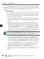
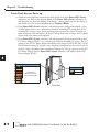
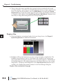
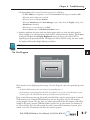
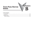
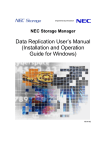
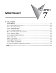
TROUBLESHOOTING
CHAPTER
8
In This Chapter...
Common Problems .................................................................................................... 8-2
Troubleshooting Flow Chart ..................................................................................... 8-3
Touch Panel does not Power up ............................................................................... 8-4
Display is Blank .......................................................................................................... 8-5
Display is Dim ............................................................................................................ 8-6
No User Program ....................................................................................................... 8-7
No Communications between Panel and PC (Personal Computer) via USB ........... 8-8
USB Driver Troubleshooting ................................................................................... 8-10
No Communications between Panel and PC (Personal Computer) via Ethernet . 8-12
No Communications between Panel and PLC ........................................................ 8-16
IP Address in System Setup Screens displays 0.0.0.0 ............................................. 8-19
Difficulty Connecting to the Panel over the Internet (Web server and
Remote Access features) ......................................................................................... 8-20
PLC Protocol Error Codes ........................................................................................ 8-21
Touch Panel Runtime Errors .................................................................................... 8-22
Panel Constantly Displays “Initializing” when Powering up ................................. 8-23
Data not Logging Problems .................................................................................... 8-23
Electrical Noise Problems ........................................................................................ 8-24
Chapter 8 - Troubleshooting
1
2
3
4
5
6
7
8
9
10
11
12
13
14
A
B
C
D
8-2
The following topics are some of the more likely problems that may be encountered during
the installation and operation of your C-more touch panel. We have made some suggestions
on what to check in order to correct the problem. Please start with the troubleshooting flow
chart that covers the more common problems encountered by other users.
Common Problems
The troubleshooting flow chart shown on the following page is based on the more common
problems fielded by our technical support team. If you are having problems, please start with
the flow chart, follow the suggestions listed, and if you still need help, call our tech support
team @ 770-844-4200. In addition to having ready the information suggested in the flow
chart, please have the following available:
1) C-more touch panel part number including serial number with date code. Why is this
information important? The various sizes of the touch panel use different processors and
memory sizes, and therefore can have different types of problems within the particular
panel size.
2) Programming software version that you are currently using. For example: Version 5.20.
Having the software version number will allow our tech support team member to assess
whether there are similar problems that have been reported when using the same version
of the software. The programming software version can be found by clicking on “About
C-more Programming Software...” selection under the Help pull down menu in the
software. Also, it is always a good practice to visit the Software/Firmware Downloads
area under the Tech Support section of the AutomationDirect website and check to see if
you are using the latest version of the programming software. If you aren’t using the latest
software version, we suggest that you upgrade to see if this resolves your problem.
NOTE: The “About C-more Programming Software...” dialog box will show a Firmware version. This is the current
firmware version that is included with the programming software and does not reflect what firmware is actually
loaded on your C-more touch panel. See the following for details on how to check the firmware version.
3) Firmware version of the C-more touch panel. For example: V5.20. The firmware version
can be checked by using the System Setup Screens, going to the Information menu
under the Main Menu, and looking under the General tab for Firmware: -Runtime. The
firmware version can also be checked by using the programming software, while connected
to the panel, and clicking on the Panel Information selection under the Panel pull down
menu. As with the programming software version, it is important for our tech support
associates to know which firmware version you are using so they can check on any known
problems. As with the programming software, we strongly suggest that the firmware
be updated to the latest version. Check for the latest version and download from the
Software/Firmware Downloads area of the AutomationDirect website.
It is also helpful to have a copy of your project file for our tech support associates to use in
troubleshooting a problem, so please be prepared to forward a copy of your project if it is
requested.
®
EA9-USER-M Hardware User Manual, 1st Ed. Rev B 01/15
Chapter 8 - Troubleshooting
Troubleshooting Flow Chart
START
PC Comm
Issue?
Yes
No
PLC Comm
Issue?
Yes
No
Blank
or Dim
Screen?
Yes
No
Try the following:
1) Check for proper grounding on panel and PC.
2) Go to section “No Communications between Panel and PC”.
3) PC connected to panel via USB:
a) If using USB Hubs, disconnect all hubs and other USB devices,
but leave USB keyboard and mouse connected.
b) Check in the Window’s device manager to see if the C-more panel’s
USB connection shows up when physically connected.
4) PC connected to panel via Ethernet:
a) Check to make sure the cable is properly connected to the correct
port on the PC and panel.
If the above steps did not resolve the problem, then contact our tech support
team with the information listed on the previous page plus the following:
a) Description of the network to which the C-more panel is connected.
b) Isolated Network or Office/Plant Network?
Try the following:
1) Check for proper DC power connection & grounding on panel & PLC.
2) Go to section “No Communications between Panel and PLC”
3) Go to section “IP Address in System Setup Screens displays 0.0.0.0”
If the above steps did not resolve the problem, then contact our tech support
team with the information listed on the previous page plus the following:
a) PLC make and model? PLC firmware version?
b) Serial or Ethernet? If serial, RS-232/422/485?
c) PLC protocol being used, and PLC comm port being used?
d) Cable purchased from ADC or constructed by user?
Having the PLC and C-more project files available to email to tech support
always helps in the troubleshooting process.
Try the following:
1) White screen? Make sure a project is loaded into the panel.
2) Black Screen? Check the PWR LED to make sure it is Steady Green.
3) Go to section “Touch Panel does not Power up”
4) Go to section “Display is Blank”
5) Go to section ”Display is Dim”
6) Check CPU LED:
a) Green - OK
b) Off - No Power
c) Red - Memory Error - cycle power to the panel, reload firmware,
d) Blinking Red - Watchdog Timer Error - cycle power, update firmware
e) Blinking Orange - Operating System Error, update firmware
f) Blinking Green - Power Loss Detection - check voltage at power source.
If the above steps did not resolve the problem, then contact our tech
support team with the information listed in this manual.
Look at the table of contents
for this chapter to see if your
particular problem is listed,
else call our tech support
team @ 770-844-4200.
EA9-USER-M Hardware User Manual, 1st Ed. Rev B 01/15
®
1
2
3
4
5
6
7
8
9
10
11
12
13
14
A
B
C
D
8-3
Chapter 8 - Troubleshooting
Touch Panel does not Power up
1
2
3
4
5
6
7
8
9
10
11
12
13
14
A
B
C
D
8-4
1.) Check the status indicators on the front of the panel to see if the Power LED (Green)
indicator is on. Refer to the diagram below. If the Power LED (Green) indicator is on
and the panel was observed showing “Initializing...” during power up, but the display is
now blank, go to the next troubleshooting tip, Display is Blank.
2.) If the Power LED (Green) indicator is off and the panel is being powered with a 12 or
24 VDC power source, use a voltmeter to check the incoming DC voltage level. If the
incoming DC voltage is zero, check any fusing that may be in the circuit. If the fuse is
open, determine cause and replace. If the DC voltage level is out of range, the DC power
source needs to be corrected or replaced.
3.) If the Power LED (Green) indicator is off and the panel is being powered with an AC/
DC Power Adapter, EA-AC, use a voltmeter to check the incoming AC power. The AC
voltage to the AC/DC Power Adapter should be in the range of 100 to 240 VAC, 50/60
Hertz. If the incoming AC voltage is zero, check any fusing that may be in the circuit. If
the fuse is open, determine cause and replace. If proper AC voltage is present on the AC/
DC Power Adapter, but the Power LED (Green) indicator is off, replace the AC/DC
Power Adapter, EA-AC.
User Defined LED (Green, Orange & Red)
Off
Power LED (Green)
Green
Red
Orange
Blinking
Red
Blinking
Orange
Blinking
Green
User Defined
(Refer to online help
file for further details)
On
Power On
Off
Power Off
Front View
®
EA9-USER-M Hardware User Manual, 1st Ed. Rev B 01/15
Chapter 8 - Troubleshooting
Display is Blank
1.) Touch the screen to make sure the panel is not in the Screen Saver mode.
• The Screen Saver will be turned off and the panel screen will display:
– If a PLC Address is configured to control the Screen Saver and changes from On to Off.
– When the panel touchscreen is touched.
– When the screen is clicked by Remote Access.
– When the Alarm Event of the Event Manager occurs. (Only when the Display setting of the
Alarm Event is checked).
– When there is a screen change by the PLC.
– When an Error such as a Communication Error occurs.
2.) If the panel is not in Screen Saver mode, check the status indicators on the rear of the
panel.
CPU Status LED (Green, Orange & Red)
Off
Green
Red
Blinking
Red
Blinking
Orange
Blinking
Green
Power Off
Normal – CPU Run State
CPU
Port2
TxD
RxD
Memory Error
Watchdog Timer Error
OS Error
Power Loss Detection
Port3
TxD
RxD
Port1 RxD
TxD
Serial TxD/RxD LED (Green)
On Comm. is active
Off No communication
Rear View
• Make sure the CPU status LED (Green, Orange, Red) is a steady Green.
• If the CPU status LED is blinking Green, then the supply voltage is below 12 VDC, or below 100
VAC when using the optional C-more AC/DC Power Adapter, EA-AC. The backlight will turn off
immediately to extend the power retention period. The panel will continue to run and the LCD
display may be slightly visible. This may be seen as the display being dim, so it is advisable to check
the incoming voltage.
• A blinking Orange CPU status LED indicates that the operating system could not be found.
Reload the firmware to the touch panel. If this does not resolve the problem, the panel must be
replaced.
Display is Blank continued on next page.
EA9-USER-M Hardware User Manual, 1st Ed. Rev B 01/15
®
1
2
3
4
5
6
7
8
9
10
11
12
13
14
A
B
C
D
8-5
Chapter 8 - Troubleshooting
1
2
3
4
5
6
7
8
9
10
11
12
13
14
A
B
C
D
8-6
3.) There is always the remote possibility that a project has been transferred to the touch
panel that includes a screen that uses a black background and has no objects placed on the
screen. To check for this possibility, access the Main Menu of the touch panel System
Setup Screens by pressing the extreme upper left corner of the panel display area for three
(3) seconds as shown below. If the System Setup Screen’s Main Menu is displayed, then
most likely an empty black background screen is being displayed.
NO USER PROGRAM
Display is Dim
1.) Check the brightness setting found under the System Setup Screens. See Chapter 5:
System Setup Screens for additional information.
2.) Backlights will lose some luminance over time causing the display to slightly dim. The
backlight average lifetime is rated at 50,000 hours and is defined as the average usage
time it takes before the brightness becomes 50% of the initial brightness. The lifetime of
the backlight depends on the ambient temperature; the lifetime decreases in low or high
temperatures. To improve the backlight life, use the Start Screen Saver function that is
available in the C-more Programming Software in the Panel Manager dialog box.
Display is Dim continued on next page.
®
EA9-USER-M Hardware User Manual, 1st Ed. Rev B 01/15
Chapter 8 - Troubleshooting
• The Screen Saver will be turned off and the panel screen will display:
– If a PLC Address is configured to control the Screen Saver and changes from On to Off.
– When the panel touchscreen is touched.
– When the screen is clicked by Remote.
– When the Alarm Event of the Event Manager occurs. (Only when the Display setting of the
Alarm Event is checked).
– When there is a screen change by the PLC.
– When an Error such as a Communication Error occurs.
3.) Another condition that may make the display appear dim is to view the touch panel in
direct sunlight or in a location where direct light is reflected onto the display. The C-more
touch panel displays have Display Brightness ratings of 280 to 310 cd/m2 (NITS),
depending on the particular model. The higher the cd/m2 (NITS) rating, the more visible
the display will be under bright lighting conditions.
NOTE: The C-more panel is not rated for direct sunlight.
No User Program
NO USER PROGRAM
If the touch screen is displaying the message “No User Program” after it has powered up, then
either:
– the built-in Flash memory does not contain a recognized project, or
– an SD memory card is plugged into the SD1 slot and there is no project on the SD memory card.
Turn the power off, remove the SD memory card and turn the power back on.
Keep in mind that on power up, the touch panel will either copy the project from its internal
Flash memory to its internal SDRAM memory and run the project, or if an SD memory
card is plugged into the SD1 slot, then any project contained on the SD memory card will be
loaded to the panel’s internal SDRAM memory and be run. In other words, the memory of
an SD card in the SD1 slot will override the panel’s internal Flash memory on power up or
reboot, even if the SD memory card does not contain a project.
EA9-USER-M Hardware User Manual, 1st Ed. Rev B 01/15
®
1
2
3
4
5
6
7
8
9
10
11
12
13
14
A
B
C
D
8-7
Chapter 8 - Troubleshooting
No Communications between Panel and PC (Personal Computer) via USB
1
2
3
4
5
6
7
8
9
10
11
12
13
14
A
B
C
D
8-8
The C-more touch panel is programmed using the C-more Programming Software,
EA9-PGMSW. The developed project is transferred from the PC to the touch panel by either
a USB or an Ethernet connection between the two. (Ethernet available on full feature units
only.)
If using USB, then a USB type AB programming cable, such as p/n USB-CBL-AB15, should
be used to make a connection between the panel’s USB Port, Type B and a USB port on
the PC. The C-more Programming Software will install a USB driver on the PC during the
software installation.
C-more
Touch Panel
PC
USB
Port
USB-CBL-ABxx
USB Cable
USB
Port
If the USB connection to the panel is recognized by the PC, you will hear the Windows
device-recognized-sound when the powered panel is connected to the PC. The driver will
appear in the Windows Device Manager as C-more HMI.
®
EA9-USER-M Hardware User Manual, 1st Ed. Rev B 01/15
Chapter 8 - Troubleshooting
No Communications between Panel and PC (Personal Computer) via USB
(cont’d)
The C-more software will then identify the USB connection with a green indicator.
This Communication indicator appears on the Panel tab in the Navigation window and in the
Project Transfer or Read from Panel windows.
EA9-USER-M Hardware User Manual, 1st Ed. Rev B 01/15
®
1
2
3
4
5
6
7
8
9
10
11
12
13
14
A
B
C
D
8-9
Chapter 8 - Troubleshooting
USB Driver Troubleshooting
1
2
3
4
5
6
7
8
9
10
11
12
13
14
A
B
C
D
8-10
Check the USB driver using Windows Device Manager:
With the C-more panel connected to the PC, on the PC, open Control Panel--> System
-->Hardware tab --> Device manager. Next expand “Universal Serial Bus controllers”.
The C-more driver is named C-more HMI as shown below:
If the C-more programming software Communication Config dialog USB indicator is red,
and the driver does not appear in Device Manager,
1) Unplug both end of the cable and replug them in.
2) If that does not establish communication, plug into a different USB port on the PC.
3) If there are any USB hubs or other devices being used, temporarily eliminate them to see if this
solves the problem.
4) Reinstall the C-more HMI USB driver.
®
EA9-USER-M Hardware User Manual, 1st Ed. Rev B 01/15
Chapter 8 - Troubleshooting
USB Driver Troubleshooting (cont’d)
The C-more USB driver installation utility is bundled with the C-more software installation
files. If you have a C-more software CD, the file is in the root, called C-moreUSBDriver.exe.
If you downloaded the software, when you extracted the files, the C-moreUSBDriver.exe was
extracted to the location you chose. First, close the C-more software and disconnect the USB
cable from the PC. Then, browse to C-moreUSBDriver.exe and run it.
Plug the USB cable into the PC and the C-more panel.
The Found New Hardware Wizard will prompt you to search for the driver. Select “No not
this time” , click Next. Select “Install the Software automatically (Recommended)” click
Next. Click Continue Anyway in the Windows Logo warning popup. Click Finish.
Open the project in the C-more software. The Communication Config (and Transfer
Project) USB indicator should be green.
EA9-USER-M Hardware User Manual, 1st Ed. Rev B 01/15
®
1
2
3
4
5
6
7
8
9
10
11
12
13
14
A
B
C
D
8-11
Chapter 8 - Troubleshooting
No Communications between Panel and PC (Personal Computer) via Ethernet
1
2
3
4
5
6
7
8
9
10
11
12
13
14
A
B
C
D
8-12
When using an Ethernet connection to communicate between the touch panel and the PC
and the communications does not seem to be working, the first area to check is the Ethernet
status indicators located next to the 10/100 Base-T Ethernet Port on the rear of the panel.
The Link Status LED must be displaying a steady or blinking green.
Link Status LED (Green)
Network Speed LED (Yellow)
On
Ethernet Linked
On
100M
Off
No Ethernet Comm.
Off
10M
Blinking
Green
Comm. Activity
1
8
If using Ethernet, there are two basic ways to make the connection. You can use an Ethernet
cable to make a direct connection between the touch panel and PC or use an Ethernet cable
from the touch panel to a switch and then to the PC.
PC
C-more
Touch Panel
Ethernet
Port
Ethernet CAT5
Cable
Auto MDI / MDI-X
Ethernet Port
Stride™
Ethernet Switch
10/100 Base-T
PC
(such as SE-SW5U)
Ethernet
Port
C-more
Touch Panel
Ethernet CAT5
Cable
Auto MDI / MDI-X
Ethernet Port
Use the C-more programming software to check the status of the Ethernet communications.
From the Navigation window, select the Panel tab. At the bottom of the Panel tab is the
Communication Config dialog box. Select the Browse button. If the connection is working
the panel will be listed in the online link list. Select the panel and then select OK. If the
Ethernet communications to the panel is working, then there should be a “green” indicator
next to the Ethernet selection. There should also be an IP Address shown in the browse box
below the Ethernet selection. If the Ethernet radio button is “red”, then you will need to
check your Ethernet cables and connections or Browse for the panel.
®
EA9-USER-M Hardware User Manual, 1st Ed. Rev B 01/15
Chapter 8 - Troubleshooting
No Communications between Panel and PC (Personal Computer) (cont’d)
There can also be a conflict with another Ethernet connection that may be using the same
IP Address. You may want to check the setup both in the touch panel and also in your PC.
As a starting point, it is best to start with an assigned IP Address and Subnet mask, mainly to
eliminate IP addressing conflicts. Use the C-more programming software and open the Touch
Panel Network dialog box under the Main Menu’s Setup drop down menu. Click on the
Ethernet Port tab to display the dialog box used to set up the touch panel’s Ethernet port.
Another cause of an Ethernet communications problem that may be encountered, is the touch
panel doesn’t show up in the node list, which can be caused by the PC having a firewall.
The figure below shows the Touch Panel Network dialog box with the Ethernet port tab
opened. The Save settings to Project check box is checked and we are using the Use the
following IP Address selection by checking its radio button. The subnet (192.168.100.X)
and the subnet mask (255.255.255.0) must be the same for both the panel and the PC.
See the C-more programming software on-line help for additional details regarding the Touch
Panel Network.
In the example shown here, the
subnet is 192.168.100.X, the
subnet mask is 255.255.255.0,
and both need to be the same
for all the Ethernet devices
connected together.
The IP Address assigned to the touch panel can also be
checked or edited by using the system setup screens built into
the touch panel. See Chapter 5: System Setup Screens for
additional information.
The figure to the left shows a different example of the
panel’s System Setup Screens’ Ethernet Port dialog box for
configuring the Ethernet port. Again, make sure the subnet
(10.11.0.x) and subnet mask (255.255.255.0) is the same for
both the panel and the PC.
EA9-USER-M Hardware User Manual, 1st Ed. Rev B 01/15
®
1
2
3
4
5
6
7
8
9
10
11
12
13
14
A
B
C
D
8-13
Chapter 8 - Troubleshooting
No Communications between Panel and PC (Personal Computer) (cont’d)
1
2
3
4
5
6
7
8
9
10
11
12
13
14
A
B
C
D
8-14
Another option for accessing the IP Address assigned to the touch panel is to use the C-more
Programming Software. Open the Navigation window’s Panel tab and click on the Browse
button under the Communication window at the bottom. This will open the Ethernet
Connection Setup window. The Online Link List tab will show all of the connected panels.
If none are shown, try clicking the Browse Network button to search for attached devices.
Double click on the Panel Name you want to access and this will bring up the Change IP
Address window. In this window changes can be made to the panel’s name, IP address, subnet
mask, and default gateway.
®
EA9-USER-M Hardware User Manual, 1st Ed. Rev B 01/15
Chapter 8 - Troubleshooting
No Communications between Panel and PC (Personal Computer) (cont’d)
Check the IP Address setting of the PC by opening the Windows operating system’s Control
Panel and then selecting the Network Connections utility. Click on Properties, scroll down
to Internet Protocol (TCP/IP) and click Properties. The Internet Protocol (TCP/IP)
Properties dialog box will open. Again, make sure the Subnet Mask is set the same for both
the panel and the PC and also make sure that the IP Addresses do not conflict.
NOTE: If a DHCP Server is being used to obtain
the IP Address for the PC, there are ways to
identify the IP Address. For example, if using
Windows XP, open a Command Prompt (Run
> CMD) and type IPCONFIG /ALL. A list of all
Ethernet assignments for the PC will be shown.
EA9-USER-M Hardware User Manual, 1st Ed. Rev B 01/15
®
1
2
3
4
5
6
7
8
9
10
11
12
13
14
A
B
C
D
8-15
Chapter 8 - Troubleshooting
No Communications between Panel and PLC
1
2
3
4
5
6
7
8
9
10
11
12
13
14
A
B
C
D
8-16
The communications between the C-more touch panel and designated PLC or controlling
device can be accomplished by either a serial connection or by an Ethernet connection to
the panel’s 10/100 Base-T Ethernet Port. (Ethernet available on full feature units only.) All
panels include a 15-pin RS-232/422/485 port. Full featured panels include a 3-wire RS-485
connection and an RJ12 RS-232 connection.
1.) If the touch panel and PLC are connected serially and the communications have seemed to
stop working, then first check the TxD and RxD status indicators on the rear of the panel
at the connected port for activity.
C-more
Touch Panel
DL-06 PLC
EA-2CBL-1
Port 2
Port 1
If there is no activity on one or both the TxD and RxD status indicators, then it should be
suspected that either:
• serial comm port settings are incorrect
• the cable is bad and needs to be replaced
• the serial port on the panel is defective
• the PLC serial port is bad
• No TxD also can indicated no tags being polled on device
CPU Status LED (Green, Orange & Red)
Off
Green
Red
Blinking
Red
Blinking
Orange
Blinking
Green
Power Off
Normal – CPU Run State
CPU
Port2
TxD
RxD
Memory Error
Watchdog Timer Error
OS Error
Power Loss Detection
Port3
TxD
RxD
Port1 RxD
TxD
Serial TxD/RxD LED (Green)
On Comm. is active
Off No communication
Rear View
The status indicators will show activity whether the serial communications is wired for
RS-232 or RS-422/485.
Electrical noise, pulse generating wiring and/or improper grounding can also cause problems
with communications. Refer to the Electrical Noise Problems section later in this chapter for
additional help.
®
EA9-USER-M Hardware User Manual, 1st Ed. Rev B 01/15
Chapter 8 - Troubleshooting
No Communications between Panel and PLC (cont’d)
The serial ports on the C-more touch panel can be tested using the panel’s system setup screens.
Access the Main Menu of the panel’s system setup screens, press the Test Menu button,
then press the Test Comm. Port button and select the appropriate port tab. You will need to
fabricate a Loop Back Connector for the type of serial connection that is being used in your
application, either RS-232 or RS-422/485, per the wiring diagrams shown below. Plug the loop
back connector into the panel’s 15-pin PLC serial communications port and then press the
Loop Back Test button to run the test. See Chapter 5: System Setup Screens for additional
information.
Loop back connector wiring diagrams:
RS-232 Loop-back Connector
15-pin D-sub
(male)
RS-422/485 Loop-back Connector
7 CTS 15-pin D-sub
(male)
8
TXD
3
RXD
7
11
CTS
TXD+
8
10
RXD–
RTS
12
TXD–
1
Wiring Diagram
RJ12
(male)
RTS
2
15
RS-232 Loop-back Connector
9
15
RXD+
1
3
RXD
4
TXD
6
1
Wiring Diagram
Wiring Diagram
System setup screens Test Comm. Port dialog boxes:
The PLC Enquiry Test can also be performed to determine if the Ethernet communication
is working correctly between the panel and designated PLC.
EA9-USER-M Hardware User Manual, 1st Ed. Rev B 01/15
®
1
2
3
4
5
6
7
8
9
10
11
12
13
14
A
B
C
D
8-17
Chapter 8 - Troubleshooting
No Communications between Panel and PLC (cont’d)
1
2
3
4
5
6
7
8
9
10
11
12
13
14
A
B
C
D
8-18
2.) If using an Ethernet connection between the touch panel and the PLC, and there is a
problem with the communications, the first area to check is the Ethernet status indicators
located next to the 10/100 Base-T Ethernet Port (shown below) on the rear of the panel.
Link Status LED (Green)
Network Speed LED (Yellow)
On
Ethernet Linked
On
100M
Off
No Ethernet Comm.
Off
10M
Blinking
Green
Comm. Activity
1
8
There are two basic ways to make the connection. You can connect directly from the touch
panel to the PLC or connect from the touch panel to a switch that is also connected to the
PLC.
H0-ECOM/H0-ECOMM100
Ethernet Module
DL06 PLC
Ethernet CAT5
Cable
C-more
Touch Panel
Auto MDI / MDI-X
Ethernet Port
Stride™
Ethernet Switch
10/100 Base-T
(such as SE-SW5U)
H0-ECOM/H0-ECOM100
Ethernet Module
C-more
Touch Panel
Ethernet CAT5
Cable
DL06 PLC
Auto MDI / MDI-X
Ethernet Port
Check the status indicators that may be included with the Ethernet communications module
or device that is part of the PLC. Refer to the PLC’s Ethernet user manual for further
troubleshooting information.
®
EA9-USER-M Hardware User Manual, 1st Ed. Rev B 01/15
Chapter 8 - Troubleshooting
No Communications between Panel and PLC (cont’d)
The Ethernet port on the C-more touch panel can be tested by using the panel’s system setup
screens. Access the Main Menu of the panel’s system setup screens, press the Test Menu
button and then press the Test Comm. Port button. Select the Ethernet tab in the Test
Comm. Port dialog box, make sure the Ethernet port is connected to an Ethernet switch or
other Ethernet communications device select a PLC from the drop down selection box, and
then press the PLC Enquiry button to run the test. See Chapter 5: System Setup Screens
for additional information.
If a PC running the C-more programming software is connected to the Ethernet network that
is also connected to both the touch panel and PLC, then certain functions in the software,
such as the Main Menu’s Setup drop down selection for Panel Manager or Touch Panel
Network and the Main Menu’s Panel drop down selection for Panel Information, can be
used to help troubleshoot problems with the touch panel’s communications and operation.
See the C-more programming software’s on-line help for additional information.
IP Address in System Setup Screens displays 0.0.0.0
NOTE: If entering an IP Address for the C-more touch panel using the System Setup Screens, and the IP Address
keeps displaying 0.0.0.0, even after entering an IP address, the panel is not functionally connected to an active
network. Either the cable, hub, or switch is bad. The entered IP Address is stored in the panel’s memory, but won’t
show up until a good connection is established. Keep in mind that if in the C-more programming software’s Touch
Panel Network dialog box, under the Ethernet Port tab, you have checked the Save settings to Project check
box and have entered an IP Address of 0.0.0.0, then anytime the project is transferred to the panel, the panel’s IP
Address will be overwritten with the entered address.
EA9-USER-M Hardware User Manual, 1st Ed. Rev B 01/15
®
1
2
3
4
5
6
7
8
9
10
11
12
13
14
A
B
C
D
8-19
Chapter 8 - Troubleshooting
1
2
3
4
5
6
7
8
9
10
11
12
13
14
A
B
C
D
8-20
Difficulty Connecting to the Panel over the Internet (Web server and Remote
Access features)
1) Refer to the software help file topics Touch Panel Network and Remote Access Setup for
information on configuring the Remote Access accounts, the Web Server Function and the
panel IP Attributes.
2) In the Ethernet Port tab if DHCP is selected for assigning the IP address, verify the currect
address of the panel. The IP address assigned by DHCP may change over time.
3) Note that the Web Server Function must be enabled on the Web Server tab before the
Remote Access Server Function can be accessed on the panel.
4) Verify that the correct TCP ports have been opened and forwarded on the router
controlling access to the network where the C-more panel resides.
5) If two C-more panels are on a network behind a firewall and they have the same Remote
Access port number, the router will use the first entry in the Port Forwarding setup that it
encounters. The same C-more panel will always come up even if the two panels have two
different Web Server Port numbers.
6) When entering the URL in Internet Explorer to connect the C-more web server using a
port number other than the default (80), be sure to use the full URL text including the
prefix “http://”. The URL should be http://xxx.xxx.xxx.xxx:aaaaa where xxx.xxx.xxx.xxx is
the IP address of the panel and aaaaa is the port number configured in the Web Server tab
of the Touch Panel Network setting.
®
EA9-USER-M Hardware User Manual, 1st Ed. Rev B 01/15
Chapter 8 - Troubleshooting
PLC Protocol Error Codes
The C-more touch panel includes built-in PLC communication protocol diagnostics that
monitor the exchange of data between the panel and the PLC. The diagnostics look for
the proper exchange of data, correct handshaking signals, addressing errors, incorrect data
bytes, wrong packet format, etc. The diagnostics also monitor and report any of the errors
that the designated PLC would normally generate if there is a problem with the PLC’s
communications. Each brand of PLC has its own unique set of diagnostic errors that are
typically communicated over the PLC’s communications port. The PLC generated errors are
interpreted by the C-more software. See the PLC manufacturer’s user manuals for additional
details on the designated PLC’s errors.
If a C-more communications error does occur, the error message will be displayed in the
upper left of the C-more screen and the Error Code is recorded in the panel’s error log. If a
PLC error occurs, the PLC error code number will appear across the top of the screen, the
PLC error message may not be included in some cases. The error log can be viewed using the
system setup screens. See Chapter 5: System Setup Screens under the Information window
to bring up the Error tab which includes a description of the logged data.
A detailed list and description of the various PLC protocol errors can be found in Appendix
A: PLC Protocol Error Codes.
PLC Protocol Error Codes example:
Error Codes for Direct LOGIC – K-Sequence
Error Code Error Message
PLC-001
PLC Communication Timeout (for single
PLC)
%Device% PLC Communication Timeout
(for multiple PLCs, such as RS-422/485)
PLC-002
NAK received from PLC
PLC-004
STX is not found
Description
A timeout occurred after sending a request to the PLC
%Device%.
%Device% indicates the device name, such as DEV001.
Example error message for multiple PLCs: DEV001 PLC
Communication Timeout
A negative acknowledgement (NAK) control code has been
generated during a read/write request.
A Start of Text (STX) control code was not found in the data
packet received from the PLC.
EA9-USER-M Hardware User Manual, 1st Ed. Rev B 01/15
®
1
2
3
4
5
6
7
8
9
10
11
12
13
14
A
B
C
D
8-21
Chapter 8 - Troubleshooting
Touch Panel Runtime Errors
1
2
3
4
5
6
7
8
9
10
11
12
13
14
A
B
C
D
The C-more touch panel includes built-in diagnostics that check for proper operation of the
panel when it is running a project that has been transferred to its memory. Faults detected
while the panel is running will produce a “Runtime” error. These errors are displayed in the
upper left of the panel’s display and are also recorded in the panel’s error log. The error log
can be viewed using the system setup screens. See Chapter 5: System Setup Screens under
the Information window to bring up the Error tab which includes a description of the logged
data.
A detailed list and description of the various touch panel runtime errors can be found in
Appendix B: Touch Panel Runtime Errors.
Touch Panel Runtime Errors example:
No.
Error
Log
Code
Error
Error Message
Message
Located at upper left of screen
Tag
Tag
Error
Code
Value
System
Screen
Info >
Error
Cause
Log Error
1
SYS ERR
Failed.
RTE-001 Log
Not enough Memory Space in %Device% ERRORCODE
2
Failed.
RTE-002 Log
%Device% cannot be found
8-22
®
SYS ERR
ERRORCODE
2001
MM/DD/YY
HH/MM/SS
Error Code
RTE-001
The size of the destination
memory is not large
enough to store the data.
2002
MM/DD/YY
HH/MM/SS
Error Code
RTE-002
No device available or
the device is defective.
EA9-USER-M Hardware User Manual, 1st Ed. Rev B 01/15
Chapter 8 - Troubleshooting
Panel Constantly Displays “Initializing” when Powering up
If the touch panel constantly displays a message reading “Initializing” while powering up, then
check the following possible causes.
1.) C-more supports USB 1.1 and 2.0 memory devices. Ensure that the USB device is 1.1 or
2.0 or backward compatible to support version 2.0
2.) The project that is loaded into the panel’s internal SDRAM memory is corrupted. Either
use the C-more programming software to clear the panel’s memory and re-transfer the
project to the touch panel, or press the upper left corner of the touch panel screen while
powering up to bypass the project and go directly to the System Setup Screen menu.
Select the Memory menu, and use either the Clear Memory or Set to Factory Default
utility to clear the panel’s memory and re-transfer the project to the touch panel. (see
Chapter 5 - System Setup Screens)
3.) An SD memory card has been plugged into an SD card slot and the SD card either has no
project stored on it or the project is corrupted. Remove the SD memory card from the SD
card slot and either load the project to the panel’s internal Flash memory, or re-format the
SD card using the SD formatter available from SDcard.org, or try a different SD memory
card.
NOTE: In the Error Log you may find the error RTE-500 - Check Sum Error, which is defined as “Memory in the
panel has been corrupted by power loss, etc.” If this is the case, try cycling power to the panel, re-transfer the
project to the panel, and re-transfer the firmware, etc. in sequential steps to try to correct the problem.
Data not Logging Problems
If the data log is missing entries, or a Runtime Error for the Log Errors as shown in Appendix
B: Touch Panel Runtime Errors is seen, then check the following possible causes.
1.) Check that the memory devices, that were selected for Data Storage under the C-more
programming software’s Main Menu - Setup drop down - Panel Manager dialog box,
are plugged into their proper location. Alarms, messages and screen captures can be
independently selected to be saved to either a USB pen drive plugged into the USB Port
- Type A, or an SD card plugged into SD Card Slot1 or SD Card Slot2 (12-inch and
15-inch panels only).
2.) Ensure that the SD card has been formatted with the SD formatter provided by SDcard.
org.
3.) The memory device could be bad. If possible, check it by plugging it into a PC that has
the ability to access the memory device. Also, not all USB devices are compatible with the
C-more touch panels. Try using the AutomationDirect USB Pen Drive, p/n
USB-FLASH. Check System Screen, Memory for the presence of the USB device
inserted.
EA9-USER-M Hardware User Manual, 1st Ed. Rev B 01/15
®
1
2
3
4
5
6
7
8
9
10
11
12
13
14
A
B
C
D
8-23
Chapter 8 - Troubleshooting
Electrical Noise Problems
1
2
3
4
5
6
7
8
9
10
11
12
13
14
A
B
C
D
8-24
Noise is one of the most difficult problems to diagnose. Electrical noise can enter a system in
many different ways which fall into one of two categories, conducted or radiated. It may be
difficult to determine how the noise is entering the system but the corrective actions for either
of the types of noise problems are similar.
• Conducted noise is when the electrical interference is introduced into the system by way of
an attached wire, panel connection, etc. It may enter through a power supply connection, the
communication ground connection, or the chassis ground connection.
• Radiated noise is when the electrical interference is introduced into the system without a direct
electrical connection, much in the same manner as radio waves.
While electrical noise cannot be eliminated, it can be reduced to a level that will not affect the
system.
• Most noise problems result from improper grounding of the system. A good earth ground can
be the single most effective way to correct noise problems. If a ground is not available, install a
ground rod as close to the system as possible. Ensure all ground wires are single point grounds and
are not daisy chained from one device to another. Ground metal enclosures around the system.
A loose wire can act as a large antenna, introducing noise into the system. Therefore, tighten all
connections in your system. Loose ground wires are more susceptible to noise than the other wires
in your system. Review Chapter 4: Installation & Wiring if you have questions regarding how to
ground the touch panel.
• Electrical noise can enter the system through the power source for the touch panel. Installing a
properly wired isolation transformer (neutral grounded) for all AC sources can help the problem,
but only if wired correctly. DC sources should be well-grounded good quality supplies.
• Never run communication cables or low-voltage power wiring close to high voltage wiring or pulse
generating wiring that controls such devices as solenoids, servos, VFDs, etc.
®
EA9-USER-M Hardware User Manual, 1st Ed. Rev B 01/15