1
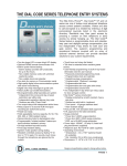
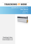
DOLKPL1KB • DOLKPS1KB
DOLKSF1KB
INSTRUCTIONAL
USER MANUAL
VIDEO
1] Connection Terminals
2] Basic Wiring Example
3] Quick Start Guide
4] Programming Guide
5] Specifications
1 Connection Terminals
The DOLKPS1KB/DOLKPS1KB/DOLKSF1KB is a secure and
waterproof keypad with three relay outputs. It works independently
as a stand-alone keypad.
WIEGAND & DATA
I/O HARNESS
BACK-LIT
JUMPER
K OR A
JUMPER
CONNECTION
TERMINALS
·
1-2
12-24V DC (Power Input Terminal)
·
3-8
·
·
·
OUTPUT 1 and OUTPUT 2 (Output Relay 1 and 2)
N.C. (Normally closed)
COM (Common ground)
N.O. (Normally open)
·
9 EG IN ( Egress Input)
·
The optional EG. IN terminal is (-) and commonly
connected to buttons. Buttons that are connected to EG.
IN will grant access when pressed.
·
10-12 O/P 3 OR BELL (Output Relay 3)
·
10 (Normally closed)
·
11 (Common ground)
·
12 (Normally open)
·
14
DU OUT (Duress Output)
· When a Duress Code is entered, the DU OUT will
switch to ground. Ex. It may be used to turn on a light,
camera, or buzzer. It may also be used to trigger an alarm
for a security system.
·
15
(-) GND (Common Ground)
·
16
·
DOOR SENS N.C. (Door Position Sensing Input - Normally Closed)
DOOR SENS must be connecting to ground if not used.
This feature can be connected to a normally closed device
(ex. A magnet) to sense a door’s status (being opened
or closed). With DOOR SENS connected, the following
features are possible:
·
Door Auto Re-lock
· The system will immediately lock after a door/
gate has been opened and closed.
·
Door Forced Open Warning
· The system will signal a warning and trigger
Alarm Output once the door is forced open without
a valid access code or egress button. The warning
signal lasts as long as programmed. Entering an
output 1 code will deactivate the warning signal.
·
Open Door Warning
· The door will signal a warning if the door is left
open for longer than the programmed time.
·
Open Door Alarm
· Open Door Alarm is designed for the
emergency door. When the door is opened without
a valid access code or egress button, the alarm
will trigger. The warning signal lasts as long as
programmed.
·
19-20 TAMPER N.C. (Tamper Switch Normally Closed Contact)
·
Normally closed while the keypad is secured on its box. It
is open when keypad is separated from its box. Connect
this to an alarm system if necessary.
·
DOOR SENS must be connecting to ground if not used.
·
LED Indicators
· Red - This becomes a solid color when Access Lock is
activated. It is also the Wiegand LED in reader mode
· Yellow - It flashes on Standby. The Yellow LED also
indicates the system’s status in synchronization with the
tones.
· Red/Green - It lights up Green for Output 1 activation;
and Red for Output 2 activation.
2 Basic Wiring Example
Basic wiring of a stand-alone door lock
NOTE:
·
·
·
Connect 1N4004 as close as possible to the lock parallel with
the lock power terminals to absorb the back EMF and prevent
keypad damage. The 1N4004 is not required for AC power.
To avoid electrostatic discharge from interfering with the
keypad, always ground the terminal.
Always connect DOOR SENS to ground.
3 Quick Start Guide
As the DOLKPS1KB/DOLKPS1KB/DOLKSF1KB is powered, it will begin
its booting process and beep for 1 minute. When the DOLKPS1KB is
finished:
Enter Programming Mode and Add Users
1
Master Code
* *
NOTE:
Default Master Code 0000
(4-8 digits)
2
0 1
#
Master Code
(4-8 digits)
3
0 2
#
User Number User Access Code
(000-999)
4
(4-8 digits)
* *
For User Access
#
User Access Code
(4-8 digits)
NOTE:
For User Access using a code only see
"Direct Access Programming with Code"
section
KEYPAD TONES AND THE LED SIGNALS
STATUS
TONES
1. In programming mode
LED SIGNALS
Solid Yellow
2. Successful key entry
1 Beep
1 Flash
3. Successful code entry
2 Beeps
2 Flashes
4. Unsuccessful code entry
5 Beeps
5 Flashes
5. Power-up delay
Continuous Beeps Continuous
Flashes
6. Output relay activation
1-second Beep
7. Standby
1 flash every
second
8. System refreshing
Quick flashes for
2.5 minutes
9. Pin already stored in
system
Long Beep
THE JUMPER FOR BACKLIT OPTIONS
Located on the upper-left corner; the two options are for full lights or
auto lights.
1. Full backlit – The keypad constantly illuminates.
2. Auto backlit – The keypad only illuminates during use.
DIRECT ACCESS PROGRAMMING WITH CODE: 8080
If you have forgotten the master code there is still a way to enter
programming mode. In order to do this you need to either have an
egress button installed, or you need to simulate an egress button.
1. First you drop the power to the keypad for one minute.
2. You then power the keypad back up and DURING the one minute
of beeping either push and hold down the egress button that has
been installed or bridge a wire from the egress in (terminal 9) to the
negative ground power (terminal 15).
3. While you are either pushing the button or with the two terminals
bridged, press
8 0 8 0
* *
4. Immediately after pressing the second *the beeping should cease
and the amber light should hold steady. At this point you are in
programming mode. Immediately upon entering programming mode
you need to create a new master code. This is accomplished by
pressing 0 1
#
New Master Code
(4-8 digits)
RESET TO FACTORY SETTINGS WITH CODE: 9999
While in programming mode, enter:
·
·
9 9 9 9
#
Allow up to 2.5 minutes for the keypad to reset. The yellow LED
will indicate when the keypad has finished resetting
Note: The current Master Code will not reset
4 Programming Chart
Feature
Begin
Programming
Mode (Solid
Yellow)
Code Entry
Master Code
End
Programming
Mode
Set Master
Code
*
Comments
*
* *
Set System into Programming Mode. The default
Master Code is 0000.
Note: All of the following
commands must be keyed
while in Programming
Mode.
Return to normal
operation.
01 Master Code #
Set your new Master
Code.
Output Number 02
Set 4-8 digit code for general access. Each unique
4-8 digit code will require
a new user number. Note:
It is important to document your user numbers
because users can be deleted and reassigned new
codes for access.
(4-8 digits)
Access Codes
Record Access
Codes (Output
1, 2, 3)
(1, 2, or 3)
User number
(000-999)
Access Code #
(4-8 digits)
Delete Access
Codes (Output
1, 2, 3)
Output Number 05
(1, 2, or 3)
Delete the user and remove their Access Code.
User number #
(000-999)
Clear all Access
Codes
Output Number
(1, 2, or 3)
00999 #
Clear all Access Codes depending on which output
relay accessed.
Visitor Codes (Output 1 only)
Set a Visitor
Code for onetime use
40 Visitor number 00
(01-50)
Visitor Code #
The Visitor Code can
only be used once until
cleared.
(4-8 digits)
Set a Visitor
Code time limit
4 Visitor number
(01-50)
Hours Visitor Code
(01-99)
(4-8 digits)...
The Visitor Code will be
cleared after the set time
limit.
Delete Visitor
Code
Clear all Visitor
Codes
40 Visitor number #
Delete the visitor’s code.
(1-50)
40 0999 #
Clear all Access Codes.
Lock Settings
Set door unlock
timer
5 Output number
(1, 2 or 3)
Seconds #
(1-99999).....
Set Access
Code to toggle
[open/close]
5 Output number
(1, 2 or 3)
0
#
Set the amount of seconds the device will grant
access before locking
again.
Entering Access Code will
toggle the lock to stay
open. Entering the Access
Code again will toggle
back to lock.
Safety Settings
Default safety
setting
60 1 #
After 10 successive false
codes, the keypad is disabled for 60 seconds
Duress safety
setting
60 2 #
After 10 successive false
codes, Duress is activated.
Entering an Access Code
/Authorization Code will
disable the Duress Output.
Extended
safety settings
60
Number of false entries
After 5-10 successive
false codes, the keypad is
disabled for 15 minutes
or until the Authorization
Code is entered.
(5-10)
#
Disable all
safety settings
60 00 #
Sound Settings
All sounds - On
7 11 #
All sounds will be enabled
All sounds - Off
7 10 #
All sounds will be disabled
Access sound 1 second buzz
7 21 #
Upon unlocking, the keypad will signal granted
access with a 1-second
buzz
Access sound 2 short beeps
7 20 #
Upon unlocking, the keypad will signal granted
access with 2 short beeps
Auto/Manual Code Entry Settings
Auto Code
Entry Mode
7 01 #
The # key after entering
an access code will NOT
be required.
Important Note: For this
feature to work, ALL
codes must be the same
number of digits as the
master code. Ex. If the
Master Code is 6-digits,
all other codes must be
the 6 digits to enable Auto
Code Entry Mode.
Manual Code
Entry Mode
7 02 #
The # key after entering
an access code will be required but all codes may
vary in digit length.
Blinking Yellow LED Settings
Blinking Yellow
LED - On
7 31 #
The amber LED will blink
every 2 seconds during
functionality
5 Specifications
Operating Voltage:
12V-24V DC, Auto adjusting
Operating Current:
40mA (quiescent) to 100mA (three relays active)
Operation Temperature:
-4 F to +158 F
Environmental Humidity:
5-95% relative humidity non-condensing
Working Environment & Ingress Protection:
All weather, IP-66
Number of Users:
Output 1 – 1,000 User PINs + 50 Duress Codes
Output 2 – 100 User PINs + 10 Duress Codes
Output 3 – 100 User PINs + 10 Duress Codes
Number of Visitor Codes:
50, programmable for one time or with the time limit
Timings for Code Entry:
10 seconds waiting for next digit entry
The Timers:
Three 1-99,999 Seconds (Over 24 Hours possible) Independent
Programmable Timers for O/P 1, 2 & 3
Egress Button:
Programmable for Instant, Delay with Warning and/or Alarm
Momentary or Holding Contact for the Exit Delay
Input Sensing Terminals:
a) Door position, b) Egress, c) O/P 1 inhibit
Output Control Terminals:
Transistor Open Collector 24VDC/100mA sink Max for the
following outputs
a) Duress, b) Alarm, c) Key Active, d) Output 3 (Door Bell
version only), e) Inter-lock
Output Contact Ratings:
Output Relay 1 – N.C. & N.O. dry contacts, 5A/24VDC Max.
Output Relay 2 – N.C. & N.O. dry contacts, 1A/24VDC Max.
Output Relay 3 – N.C. & N.O. dry contacts, 1A/24VDC Max.
(N.O. contact only for Door Bell version)
Tamper Switch – N.C. dry contact, 50mA/24VDC Max.
Specifications are subject to change for modification without
notice
TRANSMITTER SOLUTIONS WARRANTY
The warranty period of this product is 12 months from the purchasing
date. During this period, if the product does not operate correctly due
to a defective component, the product will be repaired or replaced at
the sole discretion of Transmitter Solutions. This warranty does not
extend to the product’s casing, which can be damaged by conditions
outside of the control of Transmitter Solutions.
EXCEPT AS SET FORTH ABOVE, TRANSMITTER SOLUTIONS MAKES
NO WARRANTIES REGARDING THE GOODS, EXPRESS OR IMPLIED,
INCLUDING WARRANTY OF MERCHANTABILITY OR WARRANTY OF FITNESS
FOR A PARTICULAR PURPOSE. BUYER MAKES NO RELIANCE ON ANY
REPRESENTATION OF TRANSMITTER SOLUTIONS, EXPRESS OR IMPLIED,
WITH REGARD TO THE GOODS AND ACCEPTS THEM “AS-IS/WHERE-IS”.
TRANSMITTER SOLUTIONS SELLS THE GOODS TO BUYER ON CONDITION
THAT TRANSMITTER SOLUTIONS WILL HAVE NO LIABILITY OF ANY KIND AS
A RESULT OF THE SALE. BUYER AGREES THAT TRANSMITTER SOLUTIONS
SHALL HAVE NO LIABILITY FOR DAMAGES OF ANY KIND, WHETHER DIRECT,
INCIDENTAL OR CONSEQUENTIAL DAMAGES, INCLUDING INJURIES TO
PERSONS OR PROPERTY, TO BUYER, ITS EMPLOYEES OR AGENTS, AS
A RESULT OF THE SALE. BUYER ALSO AGREES TO HOLD TRANSMITTER
SOLUTIONS HARMLESS FROM ANY CLAIMS BUYER, OR ANY THIRD PARTY,
MAY HAVE AS A RESULT OF BUYER’S USE OR DISPOSAL OF THE GOODS.
BUYER HAS READ THIS DISCLAIMER AND AGREES WITH ITS
TERMS IN CONSIDERATION OF RECEIVING THE GOODS.
7380 S. Eastern Ave, Suite 124-320 • Las Vegas, NV 89123
(866) 975-0101 • (866) 975-0404 fax
www.transmittersolutions.com