1
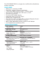
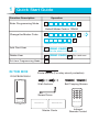
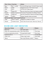
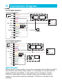
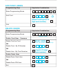
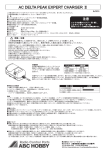
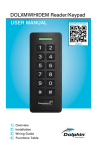
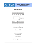
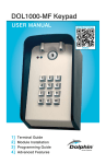
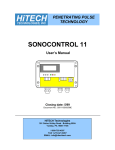
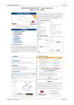
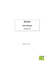
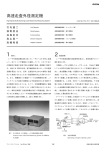
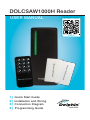
DOLCSAW1000H Reader
USER MANUAL
INSTRUCTIONAL
VIDEO
1]
2]
3]
4]
Quick Start Guide
Installation and Wiring
Connection Diagram
Programming Guide
The DOLCSAW1000H is a single door multifunction standalone
access controller.
FEATURES
•
•
•
•
•
•
•
•
•
•
•
•
Waterproof, conforms to IP66
One relay, remote infrared programmer
1,000 users (998 common users + 2 panic users)
Can be set to read EM card, HID card, or both
Card block enrolment
Tri-colour LED status display
Integrated alarm & buzzer output
Pulse mode, Toggle mode
Can add and use 4~6 digits PIN on Infrared Remote Control
2 devices can be interlocked for 2 doors
Built in light dependent resistor (LDR) for anti tamper
Low temperature resistance(-40ºF)
SPECIFICATIONS
User Capacity
Common User
Operating Voltage
Idle Current
Proximity Card Reader
Radio Technology
Read Range
1000
998
12~24VAC/DC
35mA
EM&HID
125KHz Proximity Card
2~6 cm
Wiring Connections
Relay Output, Exit Button
Relay
One (NO, NC, Common)
Adjustable Relay Output Time 1~99 Seconds (5 seconds default)
2 Amp Maximum
Lock Output Load
Environment
Operating Temperature
Operating Humidity
Physical
Color
Dimensions
Unit Weight
Shipping Weight
Meets IP66
-40˚C ~60˚C (-40˚F ~140˚F )
0~98%RH
ABS Shell
Black (White optional)
L120mm ×W48mm ×D20mm
150g
220g
1
Quick Start Guide
Function Description
Operation
#
*
Enter Programming Mode
Master Code
Default Master Code is 123456
#
0
Change the Master Code
New Master Code
#
Repeat New Master Code
Add Card User
1 (READ CARD) #
Cards can be added continuously
Delete User
2 (READ CARD) #
Exit from Programming Mode
*
IN THE BOX
For card user
Diode IN4004 (For relay circuit protection)
DOLCSAW1000H
Wall Anchors
Screw Driver
Self Tapping Screws
3
1
2
4
5
6
7
8
9
*
0
#
Remote Control
Master Add Card
Master Delete Card
Master Cards
Infrared
Remote Control
2
Installation and Wiring
• Remove the back cover from the unit
• Drill 2 holes(A,C) on the wall for the screws and one hole for
the cable
• Knock the supplied rubber bungs to the screw holes(A,C)
• Fix the back cover firmly on the wall with 4 flat head screws
• Thread the cable through the cable hole(B)
• Attach the unit to the back cover
Wall
A:φ5mm
B:φ10mm
C:φ5mm
Step3
Step2
Step1
70mm
35mm
Wire Color Function
Notes
Red
AC 1 (+DC)
12-24V AC Power Input, 12-24V DC Power Input
Black
GND
Negative Pole of DC Power Input
Pink
AC2
12-24V AC Power Input
Blue
Relay NO
Normally Open Relay Output (install diode provided)
Purple
Relay Common Common Connection for Relay Output
Orange
Relay NC
Normally Closed Relay Output (Install diode provided)
Yellow
OPEN
Output (Install diode provided)
Advanced Input and Output Features
Grey
Alarm Output
Negative contact for Alarm
Brown
Contact Input
Door/Gate Contact Input (Normally Closed)
SOUND AND LIGHT INDICATION
Operation Status
LED
Buzzer
Stand by
Red light bright
----
Enter into programming mode Red light blinks
One beep
In the programming mode
Orange light bright
One beep
Operation error
-----
Three beeps
Open lock
Green light bright
One beep
Alarm
Red light Shines quickly
Beeps
3
Connection Diagram
DC POWER SUPPLY
COM
AC2
AC 1/DC +
OPEN
D_ IN
ALARM -
D0
D1
GND
-
Orange
Purple
K-
Magnetic
Lock or
Fail-Safe
Lock
Fail-secure
lock
+
Pink
In4004
NC
Blue
In4004
NO
K+
GND
Red
Yellow
+12~24V
Exit Button
DC Power Supply
Brown
+
Door Contact
Grey
DC Alarm
Green
White
Black
AC POWER SUPPLY
COM
AC2
AC1/ DC+
OPEN
D _ IN
ALARMD0
D1
GND
-
Orange
Purple
K-
Magnetic
Lock or
Fail-Safe
Lock
Fail-secure
lock
+
Pink
K+
AC 2
Red
Yellow
AC 1
Exit Button
AC 12~24V
AC Power Supply
Brown
Grey
In4004
NC
Blue
In4004
NO
Door Contact
Green
+
-
DC Alarm
+
DC Power
White
Black
IMPORTANT
When use AC power supply, it must be connected with the Red wire(AC1)
and the Pink wire (AC2) of the reader. It is forbidden to connect the AC
power to Black wire (GND), or the reader will be damaged. Install a
1N4004 or equivalent diode is needed when use a common power
supply, or the reader might be damaged. (1N4004 is included in the
packing).
3
Programming
PROGRAMMING BY INFRARED REMOTE CONTROL
Programming will vary depending on access confirguration. Follow
the instructions according to your access configuration.
• User ID number: Assign a user ID to the access card in order to
track it. The common user ID number can be any number fom 0~997,
the panic user ID is from 998~999. IMPORTANT: User IDs do not
have to be proceeded with any leading zeros. Recording of User ID is
critical. Modifications to the user require the User ID be available.
• Proximity Card: Any 125KHz industry standard 26 bit EM and HID
Proximity card or Tag.
ADD COMMON USERS
Programming Step
Enter Programming Mode
Keystroke Combination
*
Master Code
#
ADD CARD USER
Add Card: Using Auto ID (Allows
S1/2/3/4-X to assign Card to next
available User IDnumber)
OR
Add Card: Select Specific ID
(Allows Master to define a
specific User ID to associate the
card to)
1 (READ CARD) #
Cards can be added continuously
#
1
User ID*
(READ CARD) #
*User ID is any number from 0-997
OR
Add Card: Block Enrolment
(Allows Master to add up to 998
cards to the Reader in a single
step.) Takes 2 minutes to program.
#
1
User ID*
(CARD QUANTITY) #
(FIRST CARD NUMBER) #
Cards' number must be consecutive;
Card quantity = number of cards to be
enrolled.
Exit
*
ADD PANIC USERS
Programming Step
Enter Programming Mode
Add Card
Keystroke Combination
*
Master Code
#
#
1
User ID*
(Read Card/Input 8/10
#
digit card number)
Exit
*
DELETE USERS
Programming Step
Enter Programming Mode
Keystroke Combination
*
Master Code
#
Delete Card User - Common
Delete Card by Card
OR
Delete Card - By ID Number
OR
Delete User - By Card Number
2 (READ CARD) #
Cards can be deleted continuously
#
2
User ID
8/10 digit
#
2 (Input
card number)
Delete Panic User
Delete Panic Card User
OR
Delete Panic PIN User
Exit
#
2
User ID*
#
2
User ID*
*
SET RELAY CONFIGURATION
Programming Step
Enter Programming Mode
Pulse Mode
OR
Toggle Mode
Keystroke Combination
*
Master Code
#
#
3
Relay Time*
*1-99 seconds. Default is 5 seconds.
3 0 #
Sets the relay to ON/OFF toggle mode
Exit
*
SET STRIKE-OUT ALARM
The strike-our alarm will engage after 10 failed card attempts
(Factory is OFF). It can be set to deny access for 10 minutes after
engaging or disengage only after entering a valid card/PIN or
Master code.
Programming Step
Enter Programming Mode
Strike-Out OFF
OR
Strike-Out ON
OR
Keystroke Combination
*
Master Code
#
6 0 #
(factory default)
6 1 #
Access will be denied
for 10 minutes
Strike-Out ON (alarm)
6 2 #
Set alarm time
5
#
Alarm Time: 0-30
Default is 1 minute. Enter Master code # or
valid user card/PIN to silence
Exit
*
SET CARD READING TYPE
Programming Step
Keystroke Combination
Enter Programming Mode
*
Master Code
9 3 #
Read EM & HID® card
OR
#
(factory default)
9 4 #
Read EM card only
OR
Read HID® card only
9 5 #
Exit
*
MASTER CARD USAGE
Using Master Card to add and delete card users
Add a Card User
1. (Read Master Add Card)
2. (Read User Card)
Repeat Step 2 for additional user cards
3. (Read Master Add Card)
Delete a Card User
1. (Read Master Delete Card)
2. (Read User Card)
Repeat Step 2 for additional user cards
3. (Read Master Delete Card)
NOTE:
• If no Master Cards added, must press the Exit Button for at
least 10 seconds before release
• Reset to Factory default, the user's information is still retained.
TO RESET TO FACTORY DEFAULT: Power off, press the Exit
Button, hold it and power on, there will be two beeps, and the
LED light turns into orange, release the exit button, then read any
two 125KHz EM card or HID card, the LED will turn into red,
means reset to Factory default successfully. Of the two cards
reading, the 1st one is Master Add Card, the 2nd one is the
Master Delete Card.
TRANSMITTER SOLUTIONS WARRANTY
The warranty period of Transmitter Solutions keypad is twenty-four (24)
months. This warranty shall begin on the date the keypad is manufactured. During the warranty period, the product will be,repaired or replaced
(at the sole discretion of Transmitter Solutions) if the product does not
operate correctly due to a defective component. This warranty does not
extend to (a) the keypad case, which can be damaged by conditions
outside the control of Transmitter Solutions, or (b) battery life of the
keypad. This warranty is further limited by the following disclaimer of
warranty and liability:
EXCEPT AS SET FORTH ABOVE, TRANSMITTER SOLUTIONS MAKES NO
WARRANTIES REGARDING THE GOODS, EXPRESS OR IMPLIED, INCLUDING
WARRANTY OF MERCHANTABILITY OR WARRANTY OF FITNESS FOR A PARTICULAR PURPOSE. BUYER MAKES NO RELIANCE ON ANY REPRESENTATION OF
TRANSMITTER SOLUTIONS, EXPRESS OR IMPLIED, WITH REGARD TO THE
GOODS AND ACCEPTS THEM “AS-IS/WHERE-IS”. TRANSMITTER SOLUTIONS
SELLS THE GOODS TO BUYER ON CONDITION THAT TRANSMITTER SOLUTIONS
WILL HAVE NO LIABILITY OF ANY KIND AS A RESULT OF THE SALE. BUYER
AGREES THAT TRANSMITTER SOLUTIONS SHALL HAVE NO LIABILITY FOR
DAMAGES OF ANY KIND, WHETHER DIRECT, INCIDENTAL OR CONSEQUENTIAL
DAMAGES, INCLUDING INJURIES TO PERSONS OR PROPERTY, TO BUYER, ITS
EMPLOYEES OR AGENTS, AS A RESULT OF THE SALE. BUYER ALSO AGREES TO
HOLD TRANSMITTER SOLUTIONS HARMLESS FROM ANY CLAIMS BUYER, OR
ANY THIRD PARTY, MAY HAVE AS A RESULT OF BUYER’S USE OR DISPOSAL OF
THE GOODS. BUYER HAS READ THIS DISCLAIMER AND AGREES WITH ITS
TERMS IN CONSIDERATION OF RECEIVING THE GOODS.
Pierce Building: 3788 West 2270 South, Suite E
Salt Lake City, UT 84120
(866) 975-0101 • (866) 975-0404 fax
www.transmittersolutions.com