Download Production Tool - USB 2K User Manual v1.2C _China Colour_
Transcript
USB Mass Production Tool
USB 2K User Manual
v1.2
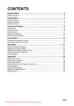
Table of Contents
A. Production Flowchart..................................................................................................1
A1.
Masked Type Controller IC ...........................................................................1
A2.
Flash Type Controller IC ................................................................................2
B. System Requirement ..................................................................................................3
C. Setting up “F1.ini” File with ParamEdt .................................................................3
D. Main Testing Window .................................................................................................4
E. Start F1 Testing .............................................................................................................5
E1. What had been tested ....................................................................................5
E2. Begin Testing .....................................................................................................5
F. Setting up “F2.ini” File with ParamEdt .................................................................9
G. Start F2 Testing ...........................................................................................................10
G1. What had been tested ..................................................................................10
G2. Begin Testing ...................................................................................................10
H. Appendix .......................................................................................................................15
H1. Default Values .................................................................................................15
H2. Mode Description ...........................................................................................15
H3. Mode Graphical Description .......................................................................17
A. Production Flowchart
A1. Masked Type Controller IC
Masked type controller IC means, that the firmware cannot be updated. (eg: PS2134 /
PS2136) The only way to update the firmware is to replace the controller. The
production flow for these type controller IC solution is as followed.
Components
SMT
F1
PCBA
F2
(function test)
[page 22]
Assembly
QC
Department
All Pictures In This Manual Are For Reference Use Only.
-1-
(function test)
[page 13]
A2. Flash Type Controller IC
Flash type controller IC means, the firmware CAN be updated. (eg: PS2044 / PS2231)
Should the firmware need to be updated, it can be done through USB port with
special software provided. The production flow for these types controller IC solution
is as followed.
Components
SMT
ISP
PCBA
F1
Assembly
F2
(function test)
[page 22]
(function test)
[page 13]
QC
Department
All Pictures In This Manual Are For Reference Use Only.
-2-
(Firmware loading)
[Done with F1]
B. System Requirement
The following is the minimum system requirement for production computers.
Pentium III 300MHz Processor or above
256MB or above RAM
Microsoft Windows 2000 SP4 or Windows XP SP2 operating system
USB 2.0 USB ports
5MB free hard disk space
Note :
We strongly recommend using Windows 2000 SP4 as the production computer
operating system.
C. Setting up “F1.ini” File with ParamEdt
The main purpose of this file is, allowing you to enter customised information, such as
Manufacture Name and Product Name of your choice. Some of these information will show
when plugging in the device to a computer, others may store in the registry.
You must set up a correct “F1.ini” file before proceed with production process.
Please refer the “ParamEdt User Manual”.
All Pictures In This Manual Are For Reference Use Only.
-3-
D. Main Testing Window
Start
Start testing.
Eject
Safe remove the devices. It is not necessary to use this function. You can
unplug the testing devices directly. Just make sure the testing procedure is
finished.
Result
When testing fail, click “Result” to see what the problem was.
GetInfo.
Read back the information of the device. Information such as firmware
information, Manufacture name, Product name, Serial number…etc.
Lock
Once testing starts, the “LOCK” function will automatically active. The lock
function will lock the parameter file selected, and ensure once testing starts,
it will not be changed.
All Pictures In This Manual Are For Reference Use Only.
-4-
E. Start F1 Testing
E1. What had been tested
During F1 test, the following testing procedures/steps will be carried out. If any of the
follow tests failed, will result in failing the test, and AP will show “RED” box to
indicate.
(a) Write some testing data to the flash memory.
(b) Read back the data copied from flash memory and compare with original data.
(c) Delete test data copied in flash memory
(d) Write customise data to “Info. Block”. (customise data from “param.ini” file)
E2. Begin Testing
Before you start testing, please make sure that you had set up “param.ini” file
correctly and successfully.
Step 1
Start the F1 testing program (F1_XX_vXXX.exe), you should see the main
window as shown below.
All Pictures In This Manual Are For Reference Use Only.
-5-
Step 2
Select the correct testing file.
Step 3
Plug in devices (USB Flash Disks) and make sure all devices had been
recognized by operating system, then click “Start” to begin testing.
Step 4
The boxes will turn yellow, meaning that the testing had begun.
All Pictures In This Manual Are For Reference Use Only.
-6-
Step 5
For some controller IC solution and/or if you had tick “Preformat” in the
parameter setting. During testing, a message window may appear and ask
you to unplug all devices and then re-insert them again.
Remove all devices from USB port and re-insert them again. Make sure all
devices had been recognized by operating system, then click “OK” to
continue testing.
Step 6
When testing finishes, the boxes will turn either “RED” or “Blue” if testing
failed; “Green” or “Orange” if testing successful.
Red : Test fail, but either normal flash is used or down grade flash had
been sorted out using our sorting tool.
Blue :
Test fail, but the down grade flash used was not sorted by our
sorting tool.
Fail status
All Pictures In This Manual Are For Reference Use Only.
-7-
Green : Test ok and either normal flash are used or down grade flash had
been sorted out with our sorting tool.
Orange : Test ok, but the down grade flash used was not sorted by our
sorting tool.
Pass status
All Pictures In This Manual Are For Reference Use Only.
-8-
Step 7
You can click “Result” to see what was the reason of the failure device(s).
F. Setting up “F2.ini” File with ParamEdt
The main purpose of this file is to check if the customised information and firmware related
information are correctly set up in F1 testing. Since this process is for double checking
purpose, therefore, you should fill in the “Expected Information” from F1.
You must set up a correct “F2.ini” file before proceed with F2 testing process.
Please refer the “ParamEdt User Manual”.
All Pictures In This Manual Are For Reference Use Only.
-9-
G. Start F2 Testing
G1. What had been tested
During F2 test, the following testing procedures/steps will be carried out. If any of the
follow tests failed, will result in failing the test, and AP will show “RED” box to
indicate.
(a) Compare firmware information and customised data.
(b) Write some testing data to the flash memory.
(c) Read back the data copied from flash memory and compare with original data.
(d) Delete test data copied in flash memory
G2. Begin Testing
Before you start testing, please make sure that you had set up “qc.ini” file correctly
and successfully.
Step 1
Start the F2 testing program (F2_vXXX), you should see the main window
as shown below.
Step 2
Select the correct testing file.
All Pictures In This Manual Are For Reference Use Only.
- 10 -
Step 3
Plug in devices (USB Flash Disks) and make sure all devices had been
recognized by operating system, then click “Start” to begin testing.
Step 4
The boxes will turn yellow, meaning that the testing had begun.
All Pictures In This Manual Are For Reference Use Only.
- 11 -
Step 5
When testing finishes, the boxes will turn either “RED” or “Green”.
Red box means that particular device had failed testing.
Red : Test fail, but either normal flash is used or down grade flash had
been sorted out using our sorting tool.
Blue :
Test fail, but the down grade flash used was not sorted by our
sorting tool.
Fail status
All Pictures In This Manual Are For Reference Use Only.
- 12 -
Green : Test ok and either normal flash are used or down grade flash had
been sorted out with our sorting tool.
Orange : Test ok, but the down grade flash used was not sorted by our
sorting tool.
Pass status
All Pictures In This Manual Are For Reference Use Only.
- 13 -
Step 6
You can click “Result” to see what was the reason of the failure device(s).
All Pictures In This Manual Are For Reference Use Only.
- 14 -
H. Appendix
H1. Default Values
Mode
VID
PID
Manufacture
Name
Product Name
Label(s)
3
13FE
XX00
(empty)
USB DISK 2.0
USB DISK
4
13FE
XX20
(empty)
USB DISK Pro
UDISK PRO
7
13FE
XX21
(empty)
USB DISK Pro
UDISK PRO
8
13FE
XX23
(empty)
USB DISK Pro
UDISK PRO
14
13FE
XX24
USB
DISK CD
USB DISK CD
21
13FE
XX27
USB
DISK CD
USB DISK CD
H2. Mode Description
Mode 3
Normal Pen Drive
Total partition :
━ No software
━ See 1 Removable drive in "My Computer".
1 partition
Mode 4
Secure Pen Drive
Total partition :
2 partitions
━ With security AP
━ See 1 Floppy drive and 1 Removable drive in "My Computer".
━ If password exist, will lock the Removable drive partition
Mode 7
Secure Pen Drive
Total partition :
2 partitions
━ With security AP
━ See 2 Removable drives in "My Computer".
━ Customer can change the partition sizes by themselves.
━ If password exist, will lock first removable partition.
Mode 8
Secure Pen Drive
Total partition :
2 partitions
━ With security AP
━ See only 1 Removable drive in "My Computer".
━ Customer can change the partition size by themselves.
━ If password exist, will lock the second removable partition.
━ Secure(private) partition can only be access when password exist.
All Pictures In This Manual Are For Reference Use Only.
- 15 -
Mode 14
CD Autorun
Total partition :
3 partitions
━ Partition 1 CD-Rom partition
━ Partition 2 HDD partition
━ Partition 3 Removable partition
━ See partition 1 & 3 in Windows 2000 / XP
━ See partition 2 & 3 in Windows ME
━ Partition 1 & 2 are read only partitions.
━ Can only see two partitions at the same time.
━ Autorun data are stored in partition 1 & 2.
Mode 21
CD Autorun
Total partition :
━ Partition 1 CD-Rom partition
━ Partition 2 Removable partition
━ See partition 1 & 2 in Windows 2000 / XP
━ Partition 1 is read only partition.
━ Autorun data are stored in partition 1.
━ Cannot autorun in Windows ME.
All Pictures In This Manual Are For Reference Use Only.
- 16 -
2 partitions
H3. Mode Graphical Description
Mode 4
Mode 7
Mode 8
Partition
1
2
2
2
Security
Function
No
Yes
Yes
Yes
Partition
Appearance
Removable
FDD
+
Removable
Removable
+
Removable
Removable
Appearance
at the same
time
1 partition
2 partitions
2 partitions
1 partition
Resize
Partition
N/A
No
Yes
Yes
Diagrammatic
Mode 3
All Pictures In This Manual Are For Reference Use Only.
- 17 -
Mode 21
Partition
3
2
Security
Function
Yes
Yes
Partition
Appearance
CD & Removable
(2000/XP)
or
HDD & Removable
(98/ME)
CD & Removable (2000/XP)
or
Removable (98/ME)
Appearance
at the same
time
2 partitions
1 or 2 partitions
Resize
Partition
No
No
Advantage
Can autorun in all Windows
OS.
No missing capacity.
Disadvantage
Need to explain to customer
about missing capacity.
Can only autorun in Windows
2000 / XP.
Diagrammatic
Mode 14
All Pictures In This Manual Are For Reference Use Only.
- 18 -


