1
EUKT05-RGBWW60
RGB + Warm White
LED Strip Lighting System
INSTALLATION & OPERATION MANUAL
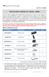
What’s in the box?
XC3-40500-RF
RGB+W LED Controller
w/ RF Remote Control
EUPS06012
60W UL Listed AC/DC 12V Power Supply
EULSP0260-5.0
RGB+WW LED Strip Lighting (16’4” ft)
2 × ACC-CN-BT-RW20
4 × ACC-CN-EE-RW20
Butt & End-to-End Connectors
SYSTEM OVERVIEW
Thanks for purchasing the EUKT05–RGBWW60 LED Strip Lighting System, designed for indirect lighting applications. Every installation is unique, and lighting effects can depend on personal preference. Installation location, surfaces,
wall colors, mounting angle, and obstacles can all affect lighting appearance.
This package includes a professional RGB + White LED controller with wireless
RF remote, a 60W UL listed AC/DC power supply, and 16’4” of LED strip lighting containing both RGB and Warm White LED modules. The XC3-40500-RF
controller is used to control RGB+W LED strip lighting and fixtures or a combination of RGB and White strip light. The white light can be either Cool White
or Warm White single-channel tape. The controller is typically mounted out of
the way, and the touch-sensitive RF remote is used to select from millions of
colors or solid white. All colors and solid white are dimmable and have eight
adjustable levels of brightness. There are 10 built-in scene modes that may
be selected from the remote, as well as adjustment controls for Brightness,
Speed, Mode Select, and Mode Pause.
Before installing this LED lighting system, please
consider your desired layout configuration:
1. Location of the power supply and LED controller
2. Wire connections to your LED strips
3. Adhesive strip mounting surface and run length
Please check your local electrical safety codes prior to beginning your project. All wiring must comply with local and national electrical codes for Class
II lighting. The 12V DC output circuits that are part of this LED lighting system meet Class II lighting requirements and are safe for DIY installation. Any
alterations or wiring modifications (i.e. hardwiring) to the 120V AC input power
supply should be completed by a licensed electrician. In some cases, you may
need to splice connecting wires to power the LED strips or make extended
turns. Again, if you are unclear as to how to install this system, please consult a
licensed electrician, and they can help turn your lighting idea into reality.
2
BEFORE YOU GET STARTED
Please keep in mind the following precautions before installation:
•
Disconnect the AC/DC power supply BEFORE making cuts or connections.
•
Do NOT install or use this system in wet or damp locations. The included
parts are rated for indoor use ONLY (IP20 NEMA rating).
•
Use LED strip lighting ONLY with a low-voltage 12V DC power source and
compatible 12/24V DC Controller.
•
ALWAYS observe the B/G/R/W/V+ indicators on the LED strip lighting in order
to maintain polarity and correct sequencing.
•
When running wires inside walls, use ONLY properly certified CL2 or better
cabling. Do NOT install Class II low voltage wiring in the same runs with AC
main power wiring. If AC and DC wires cross, keep them at 90° angles.
•
Do NOT operate the LED strip lights while they are coiled on the plastic reel.
Excessive heat from LED operation may cause the reel to melt.
•
To protect your eyes, do NOT look directly at the LEDs while they are lit.
CONTROLLER I/O WIRING DETAILS
INPUT FROM POWER SUPPLY
12/24V DC Power Supply required.
Power to load. Maintain polarity.
V+ = Hot Wire (Red)
V– = Common (Black or White)
ANT = Not Used
OUTPUT TO LED STRIPS
Connect RGB+W or two separate
RGB and W strips. Can be either
CW or WW strips.
B = Blue (NOT Black)
G = Green
R = Red
W = White (–)
V+ = Black
3
EXAMPLE LAYOUT CONFIGURATIONS
Using 1 RGB+WW LED Strip
Using 2 LED Strips: 1 RGB + 1 Warm White (or Cool White)
Need help?
We’re happy to answer your layout
and installation questions at our
toll-free hotline during normal
business hours: (888) 535-9580.
4
LED STRIP INSTALLATION
Cutting & Connecting LED Strips
To divide a 16’4” reel of RGB+WW LED strip lighting into smaller sections for
shorter runs, cut and join shorter strands using the included connectors.
Butt Connectors are ideal for immediate,
straight connections between strips.
End-to-End Connectors allow connections
around corners and at oblique angles.
1.
Locate the cut line on the RGB+WW LED strip (RGB
version strip shown in photos).
2.
Using only sharp scissors, cut evenly across the solder
pads at an exact angle 90° degrees to the LED strip.
3.
Unlatch the lids on both ends of a Butt or End-to-End
Connector and insert the LED strip completely into one
side’s groove, guiding the strip UNDER the plastic guard
edges so that the copper pads are positioned BENEATH
the connector pins. Repeat for the second LED strip on
the other side of the connector.
4.
Snap both connector lids down to tightly close the
connector. Before proceeding with mounting and final
installation, power on and test the LED strip layout to
verify proper connections and correct LED operation.
5.
To use one half of an End-to-End Connector for splices, you must observe the
B/G/R/W/V+ indicators on the LED strip in order to establish correct wiring.
Mounting the LED Strips
1.
First, ensure that the mounting surface area is clean.
The area should be free from oil or waxes and should
be smooth and dry to allow proper adhesion of the 3M
adhesive tape on the LED strip lighting’s back side.
2.
Plan a clear, straight path for a strip run. Avoid sharply bending or twisting the LED strip at curves, as this
could damage the LED modules and their connections.
3.
Gently remove the backing from the 3M adhesive side and press sections of
the strip between the LED modules to securely contact the surface of the
mounting surface. Avoid pressing on individual LED modules, as this could
also damage their solder connections to the strip.
5
CONTROLLER OPERATION
Operation via RF Remote Control
WHITE LIGHT BUTTON
Use to stop any color or dynamic
scene and change to all-white with
full dimming ability.
BRIGHTNESS
ADJUSTMENT
Down
Up
MODE SELECTION BUTTON
Use to select any of the 10 built-in
dynamic scene modes.
POWER BUTTON
Use to turn the
lighting system on
or off. Controller will
memorize the last
setting and recall
when powering up.
COLOR WHEEL
Touch sensitive color
wheel allows for 16+
million colors. Select
color by running your
finger over the corresponding color along
the outer ring. All
colors are dimmable.
REMOTE CONTROL SYNC
Each RF remote control has a unique ID code and an operation range of about 33
feet. A single remote can be synchronized with up to 20 controllers. The power-off
memory function will retain the last sync and mode upon powering up again.
HOW TO SYNC: Turn on the controller, then press and hold the BRIGHT+ button
for 3 seconds. If successful, connected LED lights will blink 3 times.
HOW TO CLEAR THE SYNC: Turn on the controller, then press the BRIGHT+ button
6 times within 3 seconds. If successful, connected LED lights will blink 6 times.
BATTERY INSTALLATION
The remote control requires 3 AAA batteries. Do not touch the color wheel or
press any button during installation. Wait 3 seconds after installation to use the
remote. Re-install the batteries if the color wheel or buttons are unresponsive.
6
CONTROLLER SCENE MODES
1.
2.
3.
4.
5.
RED, GREEN, BLUE (slow change)
RED & GREEN (slow change)
RED & BLUE (slow change)
GREEN & BLUE (slow change)
ALL COLORS (slow change)
6.
7.
8.
9.
10.
RED, GREEN, BLUE (fast change)
ALL COLORS (fast change)
RED (fading)
GREEN (fading)
BLUE (fading)
CONTROLLER SPECIFICATIONS
Input Voltage12/24VDC
Channels
4 (RGB+W)
Current Load
5A max × 4 channels
Output Power
480W max
Operating Temp.
-35° to 55° C
RF Control Range 60–90 feet
Controller Size
Remote Size
Remote Type
Brightness Adj.
Built in Modes
Memory Function
65 x 64 x 24 mm (LWH)
120 x 72 x 50 mm (LWH)
RF touch color wheel
8 levels of dimming
10 automatic programs
Power Off/On
TROUBLESHOOTING GUIDE
PROBLEM
REASON
SOLUTION
Connected lights
not working
Wire connection
issue
Check RGB & WHT connections. V+ is the
black wire on RGB strips, and V- is the
black wire on WHT strips.
Power issue
Check the power supply output and power
cord connections.
Wrong colors
RGB wire connection
issues
Check RGB connections. V+ is for the black
wire—not the blue wire.
Remote not working
Battery or distance
issue
Check polarity of batteries, re-install, and
move closer to the controller.
Remote responds
slowly
Battery issue
Batteries are low on charge. Replace them
with fresh ones.
Abnormal flicker
Voltage drop issue
Increase the wire gauge between connections.
Power issue
Not enough power. Make sure your power
supply is adequate for the load.
Signal loss
Add repeaters and power supplies based
on the load of the strips as necessary.
Interference issue
Clear ID code on remote and re-sync.
Signal corruption
7
THREE YEAR LIMITED PRODUCT WARRANTY
PRODUCT
WARRANTY
EuControls
Corporation
(“EuControls”)
warrants that at the time of shipment, the standard products manufactured
by EuControls, and sold hereunder, will be free from defects in material and workmanship for a period of three (3) years from the date of shipment.
WARRANTY ADJUSTMENT Buyer shall notify EuControls immediately if any
defect within the warranty period should appear. EuControls agrees to repair or furnish a replacement for, but not install, any product which within three (3) years from the date of shipment by EuControls, shall upon examination by EuControls, prove defective within the above warranty period. No
product will be accepted for return or replacement without written authorization of EuControls. Upon such authorization, and in accordance with instructions
by EuControls, the product will be returned shipping charge prepaid by Buyer. Replacements made under this warranty will be shipped prepaid by Seller.
EXCLUSIONS FROM WARRANTY This warranty does not extend to any products manufactured by EuControls which has been subjected to misuse, neglect, accident, improper installation or use in violation of instructions furnished by EuControls. This warranty does not extend to, or apply to, any unit
which has been repaired or altered other than at EuControls’ factory, or by persons not expressly approved by EuControls. Components purchased or made
by Buyer from any supplier other than EuControls shall bear only the warranty
given by the manufacturer of that product, and EuControls assumes no responsibility for the interface of its product with any other product, and such responsibility shall remain with Buyer for interface, functionality, and intended use.
NOTICE The foregoing warranty is in lieu of and excludes all other expressed
or implied warranties of merchantability or fitness for use or otherwise.
EuControls Corp.
19210 S Vermont Ave, Bldg C
Gardena, CA 90248
United States
Toll-Free: (888) 535-9580
Tel: (310) 643-5700
Fax: (310) 643-5688
© 2015 EuControls Corp. All rights reserved.
ACC-ML-EUKT05 v2



![LL STAGE 6-06D W - [2013.07.04]](http://vs1.manualzilla.com/store/data/005734810_1-c52217095191e9110aa67fdeef6b5f60-150x150.png)