1
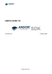
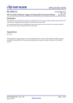
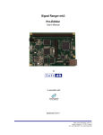
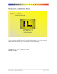
DAQ Driver and Data Logger for Signal Ranger Mk3
User’s Manual
In association with
October 30 2009
1040, avenue Belvédère, suite 215
Québec (Québec) G1S 3G3 Canada
Tél.: (418) 686-0993 Fax: (418) 686-2043
Contents
1.0
Main Features ...........................................................................................3
1.1 Software Technical Data............................................................................... 3
1.2 Hardware Technical Data ............................................................................. 3
2.0
Data Logger Interface ...............................................................................4
2.1 Acquisition Set-up Tab ................................................................................... 6
2.2 Acquisition .......................................................................................................... 8
3.0
DAQ Driver ...............................................................................................11
3.1 LabView DAQ Driver...................................................................................... 11
3.1.1 LabView DAQ driver Example ...................................................................... 11
3.1.2 Description of LabView DAQ driver functions ........................................... 13
3.2 DLL Version of the DAQ Driver .................................................................. 18
3.2.1 Execution Timing and Thread management .............................................. 18
3.2.2 Calling Conventions ...................................................................................... 18
3.2.3 Building A Project Using Visual Studio....................................................... 18
3.2.4 Description of the DLL API Functions ......................................................... 19
3.2.5 Visual Studio 2005 Example ........................................................................ 26
SRMk3 DAQ Driver/Datalogger - User’s Manual
2
1.0 Main Features
The DAQ Driver and Data Logger presented in this document are multi-purpose software tools
allowing a real time multi-channel acquisition while connected with the USB Signal Ranger Mk3
DSP board from Soft dB (see http://www.softdb.com/a-dsp_30_0_1.html ).
This software includes a ready-to-use data logger application and a general-purpose DAQ driver
(API) for the development of custom acquisition applications.
This manual describes the data logger interface and the DAQ driver (API). Before going to a
detailed description of the software, here is the technical data for both software and hardware.
Note:
There are two software installers:
1) One package for the LabView developer that includes all DAQ driver and data logger VIs.
The installation file is a simple .zip file named: SR3_DAQdriver_Labview.zip. This .zip file
contains the SR3_DAQDriver.lvlib.
2) One package for the Visual Studio developers (or others programming languages that
support the DLL function calls) that includes a library (DLL) for the DAQDriver and an
executable version of the data logger application. Also, a Visual Studio example that
illustrates the use of the DAQDriver library.
1.1 Software Technical Data
•
•
•
•
•
•
•
Compatible Windows 2000, XP and Vista (32-bits and 64-bits version)
Audio bandwidth real time acquisition/data-logging for up to 6 inputs/6 outputs through a
USB link
Data-logging in a .wav file format
Easy to use configuration and acquisition interface
Real time saturation monitoring for all 6 input channels
Real time monitoring of input and output time signals
Open source DAQ driver (API) for custom acquisition applications (LabView, Visual
Studio, C/C++, Visual Basic, etc…).
1.2 Hardware Technical Data
•
•
•
•
•
•
•
•
High speed USB 2.0 for real-time acquisition
6 analog I/Os 24-bits
Sampling rate up to 96 kHz per channel
SNR: 100 dB (input and output)
2 input types on inputs #5 and #6: Direct or Microphone
Anti-aliasing filter on all outputs and inputs
Input dynamic range (+-3.0 V)
Output dynamic range (+-2.1 V)
SRMk3 DAQ Driver/Datalogger - User’s Manual
3
2.0 Data Logger Interface
The data logger application can be found in the folder:
c:\Program Files\SR3_DAQDriver\
The data logger program file is named SR3_Datalogger.exe. This application has two tabs: one
for the Set-up and one for the Acquisition:
Data logger interface (Set-up tab)
Note: Run this application in administrator mode if you use Windows Vista. Without this
precaution, the data logger application will not be able to save recorded data in the folder
c:\Program Files\SR3_DAQDriver\.
SRMk3 DAQ Driver/Datalogger - User’s Manual
4
Data logger interface (Acquisition tab)
When launched, the Data Logger interface loads the SignalRangerMk3 board with the DSP code
SR3_DAQDriver.out. Before starting the acquisition, the user has to set his acquisition
parameters in the Set-up tab.
SRMk3 DAQ Driver/Datalogger - User’s Manual
5
2.1 Acquisition Set-up Tab
Sampling Rate
Sampling rate:
The sampling rate can be adjusted from 4 kHz to 96 kHz. Some sampling rate selections used
the double speed mode (DSM). At 96 kHz, the real time acquisition is not possible when all inputs
and outputs are selected because of the USB bandwidth (a maximum total of 9 inputs and
outputs can be used at 96 kHz).
Input Set-up
ON/OFF:
This green dot includes or excludes an input during the acquisition.
Input Select:
This control is available for inputs #5 and #6 only. The input type selection can be either direct or
microphone independently on both inputs. The microphone input includes a 3 Hz high pass filter
and can drive an electret type microphone (1 kOhms load).
Input file Path
The acquisition can be done with a log in a .wav file. To do that, the button Use input file must be
set and a file path must be specified. Use the folder icon to specify the path of the .wav file. If the
acquisition is started with the button Start/Stop (with input log), the interface creates a .wav file
and saves the input signals in a 32-bits format (24-bits right justified). The interface uses the
extended wave format that supports multi-channels and continuous sampling frequency
adjustment. LabView (8.0 and later) supports this .wav format. Windows with DirectX 8.0 module
also supports this format.
SRMk3 DAQ Driver/Datalogger - User’s Manual
6
Output Set-up
ON/OFF:
This green dot includes or excludes a specific output during the acquisition. Note that a .wav file
must be specified to allow the generation of an output signal. If no .wav file is specified, no signal
will be generated even if outputs are ON. Also, the sampling frequency used for the generation is
the sampling frequency of the acquisition board, not the sampling frequency specified in the .wav
file.
Output file Path
If an output .wav file is specified, the outputs generate the 32-bit format signals read in the file
during the acquisition. To do that, the Use output file button must be set and a file path must be
specified. Use the folder icon to specify the path of the .wav file. Note that the number of
channels in the .wav file must be the same as the number of channels selected in the data logger
interface (see the Current Output File Info indicator). Also, the sampling frequency used for the
generation is the sampling frequency of the acquisition board, not the sampling frequency
specified in the .wav file. When a .wav file is used for the outputs, the acquisition stops by itself
when the end of the file is encountered.
The .wav file must be the extended wave format (32-bits and 24-bits right justified) that supports
the multi-channels and the continuous sampling frequency adjustment. LabView (8.0 and later)
supports this .wav format. Windows with DirectX 8.0 module also supports this format.
Save and recall a configuration
These functions allow saving and recalling a configuration of the data logger. Note that the
configuration file does not include the path of the .wav files for both input and output.
SRMk3 DAQ Driver/Datalogger - User’s Manual
7
2.2 Acquisition
Starting the acquisition:
When all acquisition parameters are set, the user can start the acquisition. The acquisition can be
started with or without log using theses controls:
Acquisition Tab:
During the acquisition process, only the acquisition tab is available. This tab shows the time
signals for selected input and output channels. Also, the saturation of all 6 input channels is
monitored.
Input and Output selection:
These controls selects the signals to show in the time graphs:
The time signal is in 32-bit format (24-bits right justified: integer values between +8388607 and 8388607). The time signal is presented blocks by blocks (4096 samples). The user can adjust the
Y scale by editing the maximum and minimum values directly on the Y scale of the graph:
SRMk3 DAQ Driver/Datalogger - User’s Manual
8
The user can also use the auto scale mode by clicking on the small padlock under the time graph:
Input saturation indicators:
These indicators turn red if saturation occurs on a specific input.
Input and output FIFO indicators:
These bars indicate if the acquisition is in real time. The acquisition uses a FIFO buffer (First In
First Out) to achieve the real time transfer of input and output data through the USB link.
For the input FIFO, the acquisition board places all input data read in a buffer. Then, the PC
reads this data when there is enough data in the buffer (by blocks of 4096 samples per channel).
For the output FIFO, the PC places all data to be sent by the outputs in a buffer in the memory of
the acquisition board. The acquisition board empties the output FIFO sample by sample at the
sampling rate.
For the data logger application, the input and output FIFOs have a size of 128000 samples per
channel. Before launching the acquisition, the output FIFO is filled with 128000 samples and the
input FIFO is emptied. During the acquisition, the input FIFO is emptied by the PC and the output
FIFO is filled by the PC. In most cases, the output FIFO stays full and the input FIFO stays empty
and the acquisition process is in real time. But, when the acquisition is done at high sampling
frequency and with many channels or if another programs running on the PC request a portion of
the CPU time, a real time acquisition problem can occur. If the acquisition cannot be achieved in
real-time, the input FIFO will grows full and the output FIFO will goes empty. In this case, we
SRMk3 DAQ Driver/Datalogger - User’s Manual
9
suggest closing all other programs in the memory of the PC and retrying the acquisition. The
monitoring of time signals and saturations can also be turned off to achieve a real time acquisition
in critical situation by setting the button Show time signal to OFF.
Note: At 96 kHz, the real time acquisition is not possible when all inputs and outputs are selected
because of the USB bandwidth (a maximum total of 9 inputs and outputs can be used at 96 kHz).
SRMk3 DAQ Driver/Datalogger - User’s Manual
10
3.0 DAQ Driver
The DAQ driver provided with the Signal Ranger Mk3 DSP board allows the development of
custom acquisition applications. This driver is available in a LabView format and in a standard
DLL format (Visual Studio or others programming languages that support the DLL function calls).
With the DAQ driver, the developer can use the Signal Ranger Mk3 DSP board to develop a
custom instrument or data logger.
To support the developer, a simple acquisition example based on the driver is provided. This
example is available in LabView and in Visual Studio. Also, all LabView sources of the Data
Logger described before in this document are also available as reference.
3.1 LabView DAQ Driver
LabView version 2009 has been used to develop the acquisition driver. The LabView functions
are in the SR3_DAQdriver_Vis virtual folder of the SR3_DAQDriver.lvlib. The next paragraphs
describe the LabView example and the acquisition LabView driver.
3.1.1 LabView DAQ driver Example
In addition to the acquisition functions, the driver includes a simple example (see VI:
SR3_DAQdriver_Example.vi). Here is the front panel of the example VI:
LabView Acquisition driver example (Front Panel)
SRMk3 DAQ Driver/Datalogger - User’s Manual
11
The VI diagram looks like this:
LabView Acquisition driver example (Diagram)
In this example, all input signals are read by the PC and sent back to the outputs. Before the
acquisition while loop, the following steps are performed:
1) Connect the PC with the SignalRangerMk3 board
2) Configure of the ADC/DAC with the VI: SR3_DAQdriver_StartAIC.vi.
3) Start the acquisition process with the VI: SR3_DAQdriver_StartAcquisition.vi. The size of
the buffers for both inputs and outputs is specified here. The maximum size for the
buffers (FIFOs) is 16777212/number of channels. For instance, with 6 channels the
maximum size for the buffers is 2796202 samples per channel. Here we used 128000
samples per channel. At 48 kHz, it means 2.67 seconds.
The acquisition loop reads and writes all input and output signals by blocks of 4096. The user can
stop the acquisition with the stop control button. After the loop, the acquisition is stopped with the
VI SR3_DAQdriver_StopAcquisition.vi and the connection with the SignalRanger Mk3 board is
closed.
SRMk3 DAQ Driver/Datalogger - User’s Manual
12
3.1.2 Description of LabView DAQ driver functions
The next paragraphs present the detailed descriptions of the LabView acquisition driver functions.
Here are some important notes before the descriptions.
Notes:
FIFOcntMax is the maximum number of samples per channel for both input FIFO and output
FIFO. This determines the delay of the FIFO. The maximum value that FIFOcntMax can take is
equal to 16777212 (size of each FIFO) divided by the highest number of enabled channels either
in input or in output. For instance, if 2 inputs and 5 outputs are used, the maximum value that can
be used is floor(16777212/5)= 3355442. For a sampling frequency of 48 kHz, this would allow a
FIFO delay of 69.9 seconds.
For proper use of the acquisition driver, care should be taken to ensure than the BlockLength
parameter during the acquisition stays below the FIFOcntMax parameter.
Both the BlockLength and the FIFOcntMax must be an even number.
SR3_DAQdriver_StartAIC
This VI sets the analog I/Os parameters and the sampling frequency and loads the DSP code.
This function starts the analog I/Os and the DSP main function, but the acquisition is not started
yet (use SR3_DAQdriver_StartAcquisition.vi to start the acquisition).
Controls:
•
BoardRef: This is the number pointing to the entry corresponding to the board in the Global
Board Information Structure. It is created by SR3_Base_Open_Next_Avail_Board.vi.
•
AIC CFG: This is a cluster of the parameters for the 6 analog I/Os.
•
error in: LabView instrument-style error cluster. Contains error number and description of
the previously running VI.
Indicators:
•
dupBoardRef: This is the number pointing to the entry corresponding to the board in the
Global Board Information Structure. It is created by SR3_Base_Open_Next_Avail_Board.vi.
Use this output to propagate the reference number to other VIs.
•
Fs(Hz): This is the exact sampling frequency used.
•
error out: LabView instrument-style error cluster. Contains error number and description.
SRMk3 DAQ Driver/Datalogger - User’s Manual
13
SR3_DAQdriver_StartAcquisition
This VI sets the acquisition parameters of the driver and starts the acquisition. If the outputs are
used, this VI fills-up the output FIFO (FIFOcntMax samples per channel).
Controls:
•
BoardRef: This is the number pointing to the entry corresponding to the board in the Global
Board Information Structure. It is created by SR3_Base_Open_Next_Avail_Board.vi.
•
FIFOcntMax: This is the maximum number of samples per channel for both input FIFO and
output FIFO. This determines the delay of the FIFO. The maximum value is equal to
16777212 (size of each FIFO) divided by the highest number of enabled channels either in
input or in output.
•
In Enable array: This is an array of 6 enable controls, one for each of the potential input
channels of the SignalRangerMk3 board.
•
Out Enable array: This is an array of 6 enable controls, one for each of the potential output
channels of the SignalRangerMk3 board.
•
Channels Data: This is an array of output signals that initializes the output FIFO before
starting the acquisition process. It must fit the number of output channels enabled and the
maximum FIFO length (FIFOcntMax). If this control is unwired, the output FIFO will be
initialized with zeros. If no output channel is enabled, this control will be ignored.
•
error in: LabView instrument-style error cluster. Contains error number and description of
the previously running VI.
Indicators:
•
dupBoardRef: This is the number pointing to the entry corresponding to the board in the
Global Board Information Structure. It is created by SR3_Base_Open_Next_Avail_Board.vi.
Use this output to propagate the reference number to other VIs.
•
error out: LabView instrument-style error cluster. Contains error number and description.
SR3_DAQdriver_StopAcquisition
This VI stops the acquisition process.
Controls:
•
BoardRef: This is the number pointing to the entry corresponding to the board in the Global
Board Information Structure. It is created by SR3_Base_Open_Next_Avail_Board.vi.
•
error in: LabView instrument-style error cluster. Contains error number and description of
the previously running VI.
SRMk3 DAQ Driver/Datalogger - User’s Manual
14
Indicators:
•
dupBoardRef: This is the number pointing to the entry corresponding to the board in the
Global Board Information Structure. It is created by SR3_Base_Open_Next_Avail_Board.vi.
Use this output to propagate the reference number to other VIs.
•
error out: LabView instrument-style error cluster. Contains error number and description.
SR3_DAQdriver_OneDAQblockLL
This VI should be used in a loop in the main application to read data from the input FIFO and to
write data to the output FIFO. Before running this VI in the main loop, the analog I/Os and the
acquisition must be started. The length of the blocks (inputs and outputs) is equal to BlockLength.
Controls:
•
BoardRef: This is the number pointing to the entry corresponding to the board in the Global
Board Information Structure. It is created by SR3_Base_Open_Next_Avail_Board.vi.
•
NbChIn: This is the number of inputs enabled.
•
Write Data (I32): This is an array of output signals that will be written in the output FIFO. It
must fit the number of output channels enabled and the BlockLength control. The format is
32-bits (24-bits right justified).
•
BlockLength: This is the desired block length for the the inputs and the outputs. This value
should be less than the FIFOcntMax parameter.
•
error in: LabView instrument-style error cluster. Contains error number and description of
the previously running VI.
Indicators:
•
dupBoardRef: This is the number pointing to the entry corresponding to the board in the
Global Board Information Structure. It is created by SR3_Base_Open_Next_Avail_Board.vi.
Use this output to propagate the reference number to other VIs.
•
Read Data (I32): This is an array of input signals that has been read from the input FIFO.
The length of each channel block is equal to the BlockLength control. The format is 32-bits
(24-bits right justified).
•
current FIFOcnt: This is the number of samples per channel in the input FIFO just before
the PC reads the input FIFO. When FIFOcnt reaches FIFOcntMax, the input FIFO is full and
the output FIFO is empty.
•
error out: LabView instrument-style error cluster. Contains error number and description.
SRMk3 DAQ Driver/Datalogger - User’s Manual
15
SR3_DAQdriver_GetCorrectFIFOcnt
This VI waits for the amount of data requested (desired BlockLength). The VI
SR3_DAQdriver_OneDAQblockLL.vi already uses this VI. This VI can also be used at the end of
the acquisition process to wait for the filling-up of the inputs FIFO and the emptying of the outputs
FIFO.
Controls:
•
BoardRef: This is the number pointing to the entry corresponding to the board in the Global
Board Information Structure. It is created by SR3_Base_Open_Next_Avail_Board.vi.
•
Desired BlockLength: This is the length of the desired acquisition block (inputs and
outputs). This value should be at least less than the FIFOcntMax parameter.
•
error in: LabView instrument-style error cluster. Contains error number and description of
the previously running VI.
Indicators:
•
dupBoardRef: This is the number pointing to the entry corresponding to the board in the
Global Board Information Structure. It is created by SR3_Base_Open_Next_Avail_Board.vi.
Use this output to propagate the reference number to other VIs.
•
current FIFOcnt: This is the number of samples per channel contained in the input FIFO.
When FIFOcnt reaches FIFOcntMax, the input FIFO is full and the output FIFO is empty.
•
error out: LabView instrument-style error cluster. Contains error number and description.
SR3_DAQdriver_ReadSaturation
This VI reads the saturation state of the inputs and resets the saturation flags on the acquisition
board for the next saturation read.
Controls:
•
BoardRef: This is the number pointing to the entry corresponding to the board in the Global
Board Information Structure. It is created by SR3_Base_Open_Next_Avail_Board.vi.
•
error in: LabView instrument-style error cluster. Contains error number and description of
the previously running VI.
Indicators:
•
dupBoardRef: This is the number pointing to the entry corresponding to the board in the
Global Board Information Structure. It is created by SR3_Base_Open_Next_Avail_Board.vi.
Use this output to propagate the reference number to other VIs.
•
Saturation State: This array contains the saturation state of the 6 input channels since the
last time the VI was run (or since the acquisition has been started).
•
error out: LabView instrument-style error cluster. Contains error number and description.
SRMk3 DAQ Driver/Datalogger - User’s Manual
16
SR3_DAQdriver_ReadMissedSampleCnt.vi
This VI reads the number of missed samples (per channel) and resets the DSP counter of missed
samples for the next read. The value read is zero when the acquisition process is in real-time
(FIFOcnt always less than FIFOcntMax).
Controls:
•
BoardRef: This is the number pointing to the entry corresponding to the board in the Global
Board Information Structure. It is created by SR3_Base_Open_Next_Avail_Board.vi.
•
error in: LabView instrument-style error cluster. Contains error number and description of
the previously running VI.
Indicators:
•
dupBoardRef: This is the number pointing to the entry corresponding to the board in the
Global Board Information Structure. It is created by SR3_Base_Open_Next_Avail_Board.vi.
Use this output to propagate the reference number to other VIs.
•
MissedSampleCnt: This is the number of missed samples since the last time the VI was
run (or since the acquisition has been started).
•
error out: LabView instrument-style error cluster. Contains error number and description.
SRMk3 DAQ Driver/Datalogger - User’s Manual
17
3.2 DLL Version of the DAQ Driver
The DLL version of the acquisition driver has been designed with C/C++ development in mind,
and has only been tested on the version 2005 of Microsoft’s Visual Studio. However, it may be
possible to use it with other development environments allowing the use of DLLs.
The C/C++ interface is provided in the form of a DLL named SR3_DAQdriver.dll. To work at runtime this DLL requires that the following file be in the same directory as the user application that
uses it:
•
SR3_DAQdriver.dll: The main DLL of the acquisition driver (API)
Furthermore, the LabView 2009 run-time engine must be installed on the computer that needs to
use the DLL. The LabView 2009 run-time engine is installed automatically during the
SignalRangerMk3 software installation. However, if the user wants to deploy an application
using the C/C++ interface, which is required to run on computers other than those on which it was
developed, the LabView 2009 run-time engine should be installed separately on those computers.
A run-time engine installer is available for free from the National Instruments web site
www.ni.com.
An example is provided, which covers the development of code in Visual Studio. This example is
discussed at the end of this chapter.
3.2.1 Execution Timing and Thread management
Two functions of the DAQ Driver DLL accessing the same SignalRanger_mk3 DSP board cannot
execute concurrently. The first function must complete before the second one can be called. Care
should be taken in multi-threaded environments to ensure that separate functions of the DLL do
not run at the same time (in separate threads). The simplest method is to ensure that all calls to
the DLL functions are done in the same thread. However, functions of the interface accessing
different boards can be called concurrently.
All the functions of the DAQ Driver DLL are blocking. They do not return until the requested action
has been performed on the board.
3.2.2 Calling Conventions
The functions are called using the C calling conventions, rather than the standard Windows API
(Pascal) conventions. Whenever a function must return a number, array or string, the
corresponding space (of sufficient size) must be allocated by the caller, and a reference to this
space must be passed to the function. Whenever a function must return an element of variable
size (an array or a string), the size of the element that has been allocated by the caller is also
passed to the function.
3.2.3 Building A Project Using Visual Studio
To build a project using Visual Studio the following guidelines should be followed. An example is
provided to accelerate the learning curve (see last section of the current chapter).
•
If the project is linked statically to the SR3_DAQdriver.lib library, it must be loaded using
the DELAYLOAD function of Visual C++. To use DELAYLOAD, add delayimp.lib to the
SRMk3 DAQ Driver/Datalogger - User’s Manual
18
•
•
•
•
project (in Visual Studio 2005, it can be found in Program Files\Microsoft Visual Studio
8\VC\lib\); in Project Properties, under Linker\Command Line\Additional Options, add the
command /DELAYLOAD:SR3_DAQdriver.dll.
Alternately, the DLL may be loaded dynamically using LoadLibrary and DLL functions
must be called using GetProcAddress. Do not link statically with the SR3_DAQdriver.lib
library without using the DELAYLOAD function.
Add #include "SR3_DAQdriver.h" in the main.
If using the DELAYLOAD function to link statically to the SR3_DAQdriver.lib library, add
SR3_DAQdriver.lib to the project.
The following files must be placed in the folder containing the project sources (these files
can be found in the folder:
C:\Program Files\SR3_DAQdriver\SR3_DAQdriver_DLL:
cvilvsb.h
extcode.h
fundtypes.h
hosttype.h
ILVDataInterface.h
ILVTypeInterface.h
platdefines.h
SR3_DAQdriver.h
SR3_DAQdriver.lib
3.2.4 Description of the DLL API Functions
The next paragraphs present the detailed description of each exported functions of the DLL API.
Here are some important notes before the descriptions.
Notes:
FIFOcntMax is the maximum number of samples per channel for both input FIFO and output
FIFO. This determines the delay of the FIFO. The maximum value that FIFOcntMax can take is
equal to 16777212 (size of each FIFO) divided by the highest number of enabled channels either
in input or in output. For instance, if 2 inputs and 5 outputs are used, the maximum value that can
be used is floor(16777212/5)= 3355442. For a sampling frequency of 48 kHz, this would allow a
FIFO delay of 69.9 seconds.
For proper use of the acquisition driver, care should be taken to ensure than the BlockLength
parameter during the acquisition stays below the FIFOcntMax parameter.
Both the BlockLength and the FIFOcntMax must be an even number.
SR3_DAQdriver_Connect_DLL
int32_t __cdecl SR3_DAQdriver_Connect_DLL(int32_t * BoardRef_Out);
Description:
This function performs the following operations:
-
Tries to find a Signal Ranger Mk3 DSP board that is connected, but presently free, on the
PC
Updates the outputs BoardRef_Out
SRMk3 DAQ Driver/Datalogger - User’s Manual
19
-
Returns an error code (0 if no error, 1 if no DSP board is detected)
Inputs:
No input.
Outputs:
-
BoardRef_Out: This is a reference number allowing access to the Signal Ranger Mk3
board. All other interface functions use this number to access the board.
Return:
-
The function returns the following error code:
0: No error
1: Signal Ranger mk3 board not found
SR3_DAQdriver_StartAIC_DLL
int32_t __cdecl SR3_DAQdriver_StartAIC_DLL(int32_t BoardRef,
uint16_t SamplingRate, uint16_t ADC_5_MUX, uint16_t ADC_6_MUX,
double *SamplingFrequencyHzOut);
Description:
This function sets the analog I/Os (AIC) parameters and the sampling frequency and loads the
DSP code. This function starts the analog I/Os and the DSP main function, but the acquisition is
not started yet (use SR3_DAQdriver_StartAcquisition_DLL function to start).
Inputs:
-
BoardRef: This is a reference number allowing access to the Signal Ranger Mk3 board.
Use the function SR3_DAQdriver_Connect_DLL to obtain this reference number.
SamplingRate: This is the sampling rate selection. See below for a detailed description
of how to select the sampling rate with this parameter.
ADC_5_MUX: use 0 to select the direct input and 1 to select the microphone input.
ADC_6_MUX: use 0 to select the direct input and 1 to select the microphone input.
Outputs:
-
SamplingFrequencyHzOut: This is the exact sampling frequency used.
Return:
-
The error code: (0) No error (1) Communication error
Sampling frequency selection:
Use the following list to select the sampling frequency:
Value for SamplingRate
Selection
SRMk3 DAQ Driver/Datalogger - User’s Manual
20
0
96 kHz (mode DSM)
1
48 kHz
2
32 kHz (mode DSM)
3
24 kHz
4
19.2 kHz (mode DSM)
5
16 kHz
6
12 kHz
7
9.6 kHz
8
8 kHz
9
6 kHz
10
4.8 kHz
11
4 kHz
Note: DSM (Double Speed Mode) is used where specified otherwise, the Simple Speed Mode
(SSM) is used.
SR3_DAQdriver_StartAcquisition_DLL
int32_t __cdecl SR3_DAQdriver_StartAcquisition_DLL(int32_t BoardRef,
uint32_t FIFOcntMaxPerCh, int32_t InitialOutputSignals[],
uint16_t INEnable[], uint16_t OUTEnable[], int32_t len, int32_t
len2, int32_t len3);
Description:
This function sets the acquisition parameters of the driver and starts the acquisition. If the outputs
are used, this function fills-up the output FIFO (FIFOcntMax samples per channel).
Inputs:
-
-
-
-
BoardRef: This is a reference number allowing access to the Signal Ranger Mk3 board.
Use the function SR3_DAQdriver_Connect_DLL to obtain this reference number.
FIFOcntMaxPerCh: This is the maximum number of samples per channel for both input
FIFO and output FIFO. This determines the delay of the FIFO. The maximum value is
equal to 16777212 (size of each FIFO) divided by the highest number of enabled
channels either in input or in output.
InitialOutputSignals: This is an array of output signals that initializes the output FIFO
before starting the acquisition process. It must fit the number of output channels enabled
and the maximum FIFO length (FIFOcntMaxPerCh). If the array is empty (length zero),
the output FIFO will be initialized with zeros. If no output channel is enabled, this control
will be ignored. The data are 32-bits (24-bits right justified) and signed (between –
8388607 and +8388607). The array is a one-dimension vector containing the output data
channel-by-channel one after the others.
IN_Enable: This is an array of 6 enable controls. Use (0) to disable a specific channel
and (1) to enable a specific channel.
OUT_Enable: This is an array of 6 enable controls. Use (0) to disable a specific channel
and (1) to enable a specific channel.
len: This is the size of the InitialOutputSignals array. This parameter must be set to
FIFOcntMaxPerCh x Number of output channel enabled. For instance, if 6 output
channels are enabled and the FIFO size is 128000: the len parameters must be set to
768000 (128000*6).
len2: This is the size of the IN_Enable array. This parameter must be set to 6.
SRMk3 DAQ Driver/Datalogger - User’s Manual
21
-
len3: This is the size of the OUT_Enable array. This parameter must be set to 6.
Outputs:
No outputs.
Return:
The error code: (0) No error (1) Communication error
SR3_DAQdriver_OneDAQblockLL_DLL
int32_t __cdecl SR3_DAQdriver_OneDAQblockLL_DLL(uint16_t NbChOut,
uint32_t BlcklengthPerCh, uint16_t NbChIn, int32_t
OutputSignals[], int32_t BoardRef, uint32_t *currentFIFOcnt,
int32_t ArrayInputSignals[], int32_t len, int32_t len2);
Description:
This function should be used periodically to read data from the input FIFO and to write data to the
output FIFO. Before running this function, the SR3_DAQdriver_StartAIC_DLL and
SR3_DAQdriver_StartAcquisition_DLL functions must be called before using this function.
Inputs:
-
-
-
NbChOut: This is the number of outputs enabled.
BlcklengthPerCh: This is the length of the acquisition block (inputs and outputs). This
value should be at least less than or equal to the FIFOcntMaxPerCh parameter set with
the function SR3_DAQdriver_StartAcquisition_DLL
NbChIn: This is the number of inputs enabled.
OutputSignals: This is an array of output signals that will be written in the output FIFO. It
must fit the number of output channels enabled and the BlcklengthPerCh parameter. The
data are 32-bits (24-bits right justified) and signed (between –8388607 and +8388607).
The array is a one-dimension vector containing the output data channel-by-channel one
after the others.
BoardRef: This is a reference number allowing access to the Signal Ranger Mk3 board.
Use the function SR3_DAQdriver_Connect_DLL to obtain this reference number.
len: This is the size of the OutputSignals array. This parameter must be set to
BlcklengthPerCh x Number of output channel enabled. For instance, if 6 output
channels are enabled and the BlcklengthPerCh is 4096: the len parameters must be set
to 24576 (4096*6).
len2: This is the size of the ArrayInputSignals array (an output parameter of the
function). This parameter must be set with the same value than len.
Outputs:
-
currentFIFOcnt: This is the number of samples per channel contained in the input FIFO
just before the PC reads the input FIFO. When FIFOcnt reaches FIFOcntMaxPerCh, the
input FIFO is full and the output FIFO is empty.
ArrayInputSignals: This is an array of input signals that has been read from the input
FIFO. The length of each channel block is equal to the BlcklengthPerCh control. The
data are 32-bits (24-bits right justified) and signed (between –8388607 and +8388607).
SRMk3 DAQ Driver/Datalogger - User’s Manual
22
The array is a one-dimension vector containing the input data channel-by-channel one
after the others.
Return:
The error code: (0) No error (1) Communication error
SR3_DAQdriver_ReadSaturation_DLL
int32_t __cdecl SR3_DAQdriver_ReadSaturation_DLL(int32_t BoardRef,
int16_t ArraySaturation[], int32_t len);
Description:
This function reads the saturation state of the inputs and resets the saturation flags on the
acquisition board for the next saturation read.
Inputs:
-
BoardRef: This is a reference number allowing access to the Signal Ranger Mk3 board.
Use the function SR3_DAQdriver_Connect_DLL to obtain this reference number.
len: This is the size of the Saturations array. This parameter must be set to 6.
Outputs:
-
Saturations: This array contains the saturation state of the 6 input channels since the
last time the function was run (or since the acquisition has been started). 0: No saturation
1: Saturation detected.
Return:
The error code: (0) No error (1) Communication error
SR3_DAQdriver_GetCorrectFIFOcnt_DLL
int32_t __cdecl SR3_DAQdriver_GetCorrectFIFOcnt_DLL(int32_t BoardRef,
uint32_t DesiredBlockLength, uint32_t *currentFIFOcnt);
Description:
This function waits for the amount of data requested (DesiredBlockLength). The function
SR3_DAQdriver_OneDAQblockLL_DLL already uses this function. This function can also be
used at the end of the acquisition process to wait for the filling-up of the inputs FIFO and the
emptying of the outputs FIFO.
Inputs:
-
BoardRef: This is a reference number allowing access to the Signal Ranger Mk3 board.
Use the function SR3_DAQdriver_Connect_DLL to obtain this reference number.
SRMk3 DAQ Driver/Datalogger - User’s Manual
23
DesiredBlockLength: This is the length of the desired acquisition block (inputs and
outputs). This value should be at least less than the FIFOcntMaxPerCh parameter.
Outputs:
-
-
currentFIFOcnt: This is the number of samples per channel contained in the input FIFO.
When FIFOcnt reaches FIFOcntMaxPerCh, the input FIFO is full and the output FIFO is
empty.
Return:
The error code: (0) No error (1) Communication error
SR3_DAQdriver_ReadMissedSampleCnt_DLL
int32_t __cdecl SR3_DAQdriver_ReadMissedSampleCnt_DLL(int32_t BoardRef,
uint32_t *MissedSampleCnt);
Description:
This function reads the number of missed samples (per channel) and resets the DSP counter of
missed samples for the next read. The value read is zero when the acquisition process is in realtime (FIFOcnt always less than FIFOcntMaxPerCh).
Inputs:
-
BoardRef: This is a reference number allowing access to the Signal Ranger Mk3 board.
Use the function SR3_DAQdriver_Connect_DLL to obtain this reference number.
Outputs:
-
MissedSampleCnt: This is the number of missed samples since the last time the
function was run (or since the acquisition has been started).
Return:
The error code: (0) No error (1) Communication error
SR3_DAQdriver_StopAcquisition_DLL
int32_t __cdecl SR3_DAQdriver_StopAcquisition_DLL(int32_t BoardRef);
Description:
This function stops the acquisition process.
Inputs:
-
BoardRef: This is a reference number allowing access to the Signal Ranger Mk3 board.
Use the function SR3_DAQdriver_Connect_DLL to obtain this reference number.
SRMk3 DAQ Driver/Datalogger - User’s Manual
24
Outputs:
No outputs.
Return:
The error code: (0) No error (1) Communication error
SR3_DAQdriver_CloseConnection_DLL
void __cdecl SR3_DAQdriver_CloseConnection_DLL(int32_t BoardRef);
Description:
This function closes the connection with the Signal Ranger Mk3 board.
Inputs:
-
BoardRef: This is a reference number allowing access to the Signal Ranger Mk3 board.
Use the function SR3_DAQdriver_Connect_DLL to obtain this reference number.
Outputs:
No outputs.
SRMk3 DAQ Driver/Datalogger - User’s Manual
25
3.2.5 Visual Studio 2005 Example
The folder c:\Program Files\SR3_DAQdriver\SR3_DAQdriverVSExample contains the sources of
a Visual Studio example.
The Visual Studio example is a very simple interface that illustrates the use of the DAQ driver
DLL. The example makes the connection with the DSP board, configures the analog I/Os and the
acquisition process and launches the acquisition. Then, by calling periodically the function
SR3_DAQdriver_OneDAQblockLL_DLL, the interface reads the input signals and sent it back to
the outputs. It is a simple example but it covers the whole acquisition process with the use of the
DLL.
Visual Studio example
The source files of this example have been created using the MFC wizard. The parts added by
Soft dB are identified with the comment Added by Soft dB.
SRMk3 DAQ Driver/Datalogger - User’s Manual
26