1
DOS/V PCI Bus
4-Axis Motor Control Board with Interpolation
MC8043P User’s Manual
2006-11-13
Ver. 1.1
NOVA electronics
MC8043P - Mi
NOVA electronics
Introduction
■ Before You Begin
Before using MC8043P, please read this manual carefully to fully understand for correct use and observe all the instructions
given in this manual. We shall be exempted from taking responsibility and held harmless for damage or losses incurred by the
user if the user fails to observe the instructions.
■ Checking the Contents
When you unpack your MC8043P package, check for the following accessories. If something is missing or broken, contact the
place of purchase.
MC8043P
1
I/O Cable
1
The user’s manual and software are not with the package for resource-saving. If you need additional manuals or software,
contact the place of purchase or contact us. You can also download the latest manual and software from our web site:
http://www.novaelec.co.jp/eng
■ MCX314As Manual
The circuit of MC8043P consists of mainly 4-axes motion control IC “MCX314As”, a PCI-bus interface circuit and I/O interface
circuits of each axis. Basic functions of this board all depend on MCX314As, so please refer to the user’s manual of MCX314As
regarding these functions. This manual describes the installation on Windows, how to use the library and the interface circuits of
PCI bus, I/O address and I/O signals.
■ Caution/Danger
Use the following environmental conditions.
Operating Temperature
0~45℃(32~113°F)
Humidity
20~90% (no condensation)
Floating dust
Not to be excessive
Corrosive gases
None
Electric supply source
DC+5V (±5%), external source: DC+12~24V
Perform inspection and maintenance periodically for correct use.
Cable connection
The connector of the board and a cable should properly be connected.
Card-edge
No dust and no corrosion.
Connector terminal area
No dust and no corrosion.
On the IC and board
No excessive dust and no foreign substance.
■ Handling Precautions
● This product is wrapped in an antistatic envelope. Before handling the product, eliminate static electricity of your body and
clothes and then hold both ends of the board between your fingers or hold a mounting bracket.
● Do not touch connector terminals and other terminals of components as much as possible. If the person who is electrically
charged touches the part, CMOS-IC can be destroyed by static electricity. Use caution to prevent any ESD in a dry condition
especially in wintertime.
● Do not use in any location subject to shock, vibration, magnetism and electricity. Otherwise, the equipment may be damaged
or malfunctioned.
● Do not disassemble, repair or modify the equipment.
● Do not connect or disconnect the board or cables while power is applied. Otherwise, breakdown or operation error may
result.
Information in this manual is subject to change without notice.
Windows are registered trademark of Microsoft Corporation.
This user’s manual supports Japanese User’s Manual Version 2006.08.30.
-i-
MC8043P - Mii
NOVA electronics
1. Outline ................................................................... 1
1.1
MCX314As Functional Restriction .................................................................................................. 2
1.2
Difference from MC8041P .............................................................................................................. 2
1.3
PCI Bus Interface ........................................................................................................................... 2
1.4
Each Axis I/O Interface ................................................................................................................... 3
2. I/O Address Setting and Register........................... 4
3. I/O Signals ............................................................. 5
3.1
I/O Connector ................................................................................................................................. 5
3.2
Drive Pulse Output Signal (nP+P, nP+N, nP-P, nP-N) .................................................................... 7
3.3
General Output Signal (nOUT7, nOUT6, nOUT5, nOUT4)............................................................. 8
3.4
Over Run Limit Input Signal (nLMT+, nLMT-) ................................................................................. 9
3.5
Decelerating Stop/Instant Stop Input Signal (nIN1, nIN2, nIN3) ................................................... 10
3.6
Input Signal for Servo Motor (nINPOS, nALARM) ........................................................................ 10
3.7
Encoder Input Signal (nECAP, nECAN, nECBP, nECBN, nINOP, nINON).....................................11
3.8
Driving by External Signal (nEXOP+, nEXOP-) ............................................................................ 13
3.9
Emergency Stop Input Signal (EMG)............................................................................................ 13
3.10 External Power (VEX)................................................................................................................... 13
4. Interrupt ............................................................... 14
5. Connection Example for Motor Driver .................. 15
5.1
Connection Example for Stepper Motor........................................................................................ 15
5.2
Connection Example for AC servo motor driver............................................................................ 16
6. Input/Output Signals Timing................................. 17
6.1
Reset
......................................................................................................................................... 17
6.2
Independent Driving ..................................................................................................................... 17
6.3
Interpolation.................................................................................................................................. 17
6.4
Input Pulse Timing ........................................................................................................................ 18
Encoder 2-phase Pulse Input ............................................................................................................... 18
Up/Down Pulse Input............................................................................................................................ 18
6.5
Instant Stop Timing ....................................................................................................................... 18
Instant Stop by External Signal............................................................................................................. 18
Instant Stop by Command .................................................................................................................... 18
6.6
Decelerating Stop Timing.............................................................................................................. 19
Decelerating Stop by External Signal ................................................................................................... 19
Decelerating Stop by Command ........................................................................................................... 19
7. Board Dimensions ............................................... 20
- ii -
MC8043P - Miii
NOVA electronics
8. Installation ........................................................... 21
8.1
Preparation of Driver Software ..................................................................................................... 21
8.2
How to Install the Board into your PC........................................................................................... 21
8.3
How to Install Device Driver ......................................................................................................... 22
8.3.1
Windows 2000...................................................................................................................................... 22
8.3.2
Windows XP......................................................................................................................................... 26
8.4
Board Removal............................................................................................................................. 29
8.4.1
8.5
Windows 2000/XP ................................................................................................................................ 29
Updating Device Driver................................................................................................................. 30
8.5.1
Windows 2000...................................................................................................................................... 30
8.5.2
Windows XP......................................................................................................................................... 33
8.6
Notes for When Connected to External Device ............................................................................ 37
9. Programming ....................................................... 38
9.1
Software Specifications ................................................................................................................ 38
9.1.1
Operating Environment ........................................................................................................................ 38
9.1.2
Program Configuration File................................................................................................................... 38
9.1.3
API (MC8043P Driver Function) ........................................................................................................... 40
9.1.4
API (Supporting Function used by MC8041P Driver) ............................................................................ 90
9.2
Contents of the Accessory Software ............................................................................................. 97
9.3
Development Procedure ............................................................................................................. 101
9.3.1
When developing applications with VC++ (VC++6.0, VC++.NET 2003) .............................................. 101
9.3.2
When developing applications with VB6.0 .......................................................................................... 103
9.3.3
When developing applications with VB.NET 2003 .............................................................................. 103
9.4
Notes on Programming............................................................................................................... 104
10. Specifications ................................................. 106
- iii -
MC8043P - M1
NOVA electronics
1. Outline
MC8043P is a PCI-bus compliant PC/AT compatible circuit board equipped with 4-axes motion control IC with interpolation
function “MCX314As”. It can independently control 4-axes of either stepper motor or pulse type servo drives for position and
speed controls. In addition, this IC can perform 2/3 axes linear interpolation, CW/CCW circular interpolation and 2/3 axes bit
pattern interpolation.
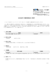
MC8043P functional block diagram is shown as follows. MC8043P consists of mainly 4-axes motion control IC “MCX314As”,
a PCI-bus interface circuit and I/O interface circuits of each axis: X, Y, Z and U. Therefore, basic functions of this board all
depend on MCX314As, so please refer to the user’s manual of MCX314As regarding these functions.
X axis I/O Interface
Crystal Oscillator
16MHz
XPP
CLK
XPM
XOUT7~4
Line Driver
26C31
Output Buffer
74LS06
XP-P/N -direction pulse output
XOUT7~4 general output 4 points
VEX external power supply (DC12~24V)
RESETN
XLMTP
Photo Coupler
XIN3~1
instant stop
XINPOS
WRN
XINPOS servo in-position
XALARM servo alarm
XALARM
RDN
XECA
A2~0
High-speed
Photo Coupler IC
XECB
XIN0
XLMT+ +direction limit *3
XLMT- -direction limit
XIN3~1 deceleration/
XLMTM
CSN
XECAP/N encoder A-phase
XECBP/N encoder B-phase
XIN0P/N encoder Z-phase *1
TLP115A
MCX314As
APIC21
PCI
Bus
XP+P/N +direction pulse output
XEXPP
PCI Interface
Adapter
Photo Coupler
XEXPM
XEXOP+ +direction driving
XEXOP- -direction driving
(ADTEC)
Y axis I/O Interface
(same as X axis)
D15~0
Z axis I/O Interface
(same as X axis)
INTN
U axis I/O Interface
(same as X axis)
EEPROM
NM93CS66
EMGN
or equivalent
For multiple
Address SW
Photo Coupler
*2
EMG Emergency stop
*1 Encoder Z-phase input signal can be input to nIN2 of MCX314As by switching jumper.
*2 Emergency stop input signal can change the logic by switching jumper.
*3 All the input signals (nECA/B excluded) of I/O interface are set to MCX314As
built-in integral filter ( τ=512μsec) due to Windows device driver dafault setting.
MC8043P Circuit Block Diagram
-1-
MC8043P - M2
NOVA electronics
1.1
MCX314As Functional Restriction
MC8043P does not support the following MCX314As input/output signals due to the board area and the number of I/O
connector pins.
BUSYN output signal
EXPLSN input signal
SCLK output signal
nDRIVE/DCC output signal
nOUT3~0 general output signal (4 points of each axis nOUT7~4 are used as output through buffer.)
1.2
Difference from MC8041P
MC8041P is a PCI board equipped with MCX314, and MC8043P is a PCI board equipped with MCX314As instead of MCX314.
Concerning I/O interface, signal names and pin assignments are completely the same as MC8041P. However, the following are
different from MC8041P for upgrade.
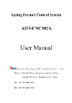
■ Input Signal Filter Circuit Deletion
In MCX314As, all the input signals excluding nECA/B signal are equipped with the integral filters in the IC. MC8043P board is
not equipped with CR filter on the board in order to effectively use these built-in integral filters. IC built-in filter sets the delay
time of all the input signals excluding nECA/B signal to 512μsec at the initial setting of Windows device driver provided by
NOVA electronics. IC built-in filter can freely change the delay time in mode setting of MCX314As.
+5 V
MCX3 14As
nLMTP
1 0K
3. 3K
nLMT+
Built-in filter
Delay time: 512μSEC (default)
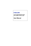
■ Encoder Z-phase Input Signal Switching
MC8041P uses nIN0 as the input of an encoder Z-phase signal. However, if the user uses automatic home search function of
MCX314As on MC8043P, nIN2 is assigned to the input of the encoder Z-phase signal. In MC8043P, short-circuiting 1 and 2 of
the jumper pin JP3, nIN0 can be used as the encoder Z-phase signal as well as MC8041P (factory default). And if
short-circuiting 2 and 3 of the jumper pin JP3, encoder Z-phase input is connected to nIN2 of MCX314As and the encoder
Z-phase signal can be input in automatic home search of MCX314As.
MCX314As
MCX314As
nIN2
General purpose
(low-speed)
Photo coupeler
nIN2
nIN2
General purpose
(low-speed)
Photo coupeler
nIN0
High-speed
Photo coupler
nIN0P Encoder Z-phase
nIN0N
nIN0
High-speed
Photo coupler
nIN0P Encoder Z-phase
nIN0N
JP3:2-3 short-circuited
JP3:1-2 short-circuited
1.3
nIN2
PCI Bus Interface
■ Occupied I/O Address
In this board, SA15~4 is address decoded and the internal 16-bit read/write register can be selected by SA3~1 of MCX314As.
The board requires 16 I/O address locations for PCI bus. I/O addressing is determined by “plug and play” function of Windows.
■ Data Length
Data length is 16-bit. Read/Write access cannot be performed per byte.
■ Interrupt Signal
When using an interrupt to PCI bus, the board uses IRQ determined by “plug and play” function of Windows.
-2-
MC8043P - M3
NOVA electronics
1.4
Each Axis I/O Interface
■ Drive Pulse Output (nP+P/N, nP-P/N)
Drive pulses in the +/- direction for motor driving are output a 50% duty cycle of from 1PPS to 4MPPS.
Drive pulse output signals of each direction are the differential line-drive output of AM26C31 line driver or equivalent.
■ General Output (nOUT7~4)
Each axis has 4 general outputs. Output buffer uses SN74LS06 or equivalent and is the open collector output. These signals can
be used as a stack counter clear, servo free and alarm reset for a servomotor.
■ Over Run Limit Input (nLMT+, nLMT-)
Input signal to disable output pulse for + and – direction respectively. Decelerating stop and instant stop for active can be
selected in mode setting. These input signals are isolated by photo coupler from internal circuit. DC12~24V power supply is
needed.
■ Decelerating Stop/Instant Stop Input (nIN3~1)
In home search, this input signal is to stop drive pulse in deceleration or immediately from outside. Enable/Disable and active
logical level can be selected in mode setting. Each axis has three inputs, also can be used as general input. These input signals
are isolated by photo coupler from internal circuit.
■ Servo Motor Input (nINPOS, nALARM)
INPOS (in-position) signal and ALARM signal for servo motor drivers can be input, which can also be used as general input
signals. These input signals are isolated by photo coupler from internal circuit.
■ Encoder Input (nECAP/N, nECBP/N, nINOP/N)
This signal inputs A/B phase and Z-phase signals from an encoder. nECAP/N, nECBP/N signals are for an encoder A/B phase
signal input and count up or down 32-bit real position counter inside MCX314As. nINOP/N signal is for a Z-phase signal input
and stops drive pulse in deceleration or immediately. In default setting, nINOP/N signal is connected to nIN0 input of
MCX314As. Short-circuiting 2 and 3 of the jumper pin JP3, this Z-phase input is connected to nIN2 of MCX314As and the user
can perform automatic home search function of MCX314As. These input signals are isolated by photo coupler from internal
circuit and can easily be connected to a differential output line-drive.
■ Driving by External Input(nEXOP+, nEXOP-)
This signal externally controls driving in the + or – direction. In fixed pulse driving mode, the input signal triggers (the falling
edge) to output specified drive pulse. In continuous pulse driving mode, drive pulse is output continuously while the input signal
is low. This function can reduce the load of the host CPU, so the user can perform jog feed of each axis speedy. These input
signals are isolated by photo coupler from internal circuit.
■ Emergency Stop Input (EMG)
This signal is to perform the emergency stop for all axes. Active logical level can be set by selecting a jumper on the board. This
input signal is isolated by photo coupler from internal circuit.
-3-
MC8043P - M4
NOVA electronics
2. I/O Address Setting and Register
I/O port address of the board is automatically determined by the plug and play function (PnP function) of the PCI bus. The board
requires serial 16 I/O address locations for PCI bus.
Check it not to overlap the I/O address of PC main board or other I/O expansion boards using [System Properties] – [Device
Manager].
I/O port address of MCX314As is as shown in the table below. The number in () of I/O address means each register address
when PnP function sets to 0280~028Fh. Each register is 16-bit length. Be sure to access by word, it cannot be accessed by byte.
For details on each register, see chapter 4 of MCX314As user’s manual.
I/O Address
SA3
0
SA2
0
SA1
0
(0280h)
0
0
1
(0282h)
0
1
0
(0284h)
0
1
1
(0286h)
1
0
0
(0288h)
1
0
1
(028Ah)
1
1
0
(028Ch)
1
1
(028Eh)
1
Write Register
Read Register
Sign
Register Name
Sign
Register Name
WR0
Command register
RR0
Main status register
XWR1
X axis mode register 1
XRR1
X axis status register 1
YWR1
Y axis mode register 1
YRR1
Y axis status register 1
ZWR1
Z axis mode register 1
ZRR1
Z axis status register 1
UWR1
U axis mode register 1
URR1
U axis status register 1
XWR2
X axis mode register 2
YWR2
Y axis mode register 2
XRR2
X axis status register 2
ZWR2
Z axis mode register 2
YRR2
Y axis status register 2
UWR2
U axis mode register 2
BP1P
BP1P register
XWR3
X axis mode register 3
YWR3
Y axis mode register 3
ZWR3
Z axis mode register 3
UWR3
U axis mode register 3
BP1M
BP1M register
WR4
Output register
BP2P
BP2P register
WR5
Interpolation mode register
BP2M
BP2M register
WR6
Write data register 1
BP3P
BP3P register
WR7
Write data register 2
BP3M
BP3M register
-4-
ZRR2
Z axis status register 2
URR2
U axis status register 2
XRR3
X axis status register 3
YRR3
Y axis status register 3
ZRR3
Z axis status register 3
URR3
U axis status register 3
RR4
Input register 1
RR5
Input register 2
RR6
Read data register 1
RR7
Read data register 2
MC8043P - M5
NOVA electronics
3. I/O Signals
This chapter describes each I/O signal of the I/O connector. In the description, the signal name of each axis is described as
n○○○○. This “n” means X, Y, Z and U.
3.1
I/O Connector
I/O Connector Pin Assignments
A1
A50
B50
B1
When implemented in PC, the connector may be upside down occasionally.
Pin 1 Mark
Cab le ( ind lude d, 1 .2m )
A 50 A49
A2 A1
B50 B49
B2 B1
The cable (included) is A1, A2, … A49, A50 from the right (red) of the upper cable to the left, and B1, B2,
… B49, B50 from the right (red) of the lower cable to the left when Pin 1 mark (▲) of the connector is
placed in the upper right.
Connector type: Board side FX2B-100P-1.27DS (Hirose), Cable side FX2B-100S-1.27R (Hirose)
Pin
Signal
A1
VEX
A2
EMG
A3
XLMT+
A4
XLMT-
A5
XIN1
A6
XIN2
I/O
Contents
Chapter
External Power (DC12~24V)
3.10
Input
Emergency Stop (All axes)
3.9
Input
X axis Limit in + direction
3.4
Input
X axis Limit in – direction
3.4
Input
X axis Decelerating Stop / Instant Stop
3.5
Input
X axis Decelerating Stop / Instant Stop
3.5
A7
XIN3
Input
X axis Decelerating Stop / Instant Stop
3.5
A8
YLMT+
Input
Y axis Limit in + direction
3.4
A9
YLMT-
Input
Y axis Limit in – direction
3.4
A10
YIN1
Input
Y axis Decelerating Stop / Instant Stop
3.5
A11
YIN2
Input
Y axis Decelerating Stop / Instant Stop
3.5
A12
YIN3
Input
Y axis Decelerating Stop / Instant Stop
3.5
A13
XINPOS
Input
X axis Servo Inposition
3.6
A14
XALARM
Input
X axis Servo Alarm
3.6
A15
XECAP
Input
X axis Encoder A-phase
3.7
A16
XECAN
Input
X axis Encoder A-phase
3.7
A17
XECBP
Input
X axis Encoder B-phase
3.7
A18
XECBN
Input
X axis Encoder B-phase
3.7
A19
XIN0P
Input
X axis Encoder Z-phase
3.7
A20
XIN0N
Input
X axis Encoder Z-phase
3.7
A21
YINPOS
Input
Y axis Servo Inposition
3.6
A22
YALARM
Input
Y axis Servo Alarm
3.6
A23
YECAP
Input
Y axis Encoder A-phase
3.7
A24
YECAN
Input
Y axis Encoder A-phase
3.7
A25
YECBP
Input
Y axis Encoder B-phase
3.7
-5-
MC8043P - M6
NOVA electronics
Pin
Signal
I/O
Contents
Chapter
A26
YECBN
Input
Y axis Encoder B-phase
3.7
A27
YIN0P
Input
Y axis Encoder Z-phase
3.7
A28
YIN0N
Input
Y axis Encoder Z-phase
3.7
A29
XEXOP+
Input
X axis Driving in + direction
3.8
A30
XEXOP-
Input
X axis Driving in – direction
3.8
A31
YEXOP+
Input
Y axis Driving in + direction
3.8
A32
YEXOP-
Input
Y axis Driving in – direction
3.8
A33
GND
A34
XOUT4
Output
X axis General Output
3.3
A35
XOUT5
Output
X axis General Output
3.3
A36
XOUT6
Output
X axis General Output
3.3
A37
XOUT7
Output
X axis General Output
3.3
A38
XP+P
Output
X axis Drive Pulse in + direction
3.2
Internal Circuit GND
A39
XP+N
Output
X axis Drive Pulse in + direction
3.2
A40
XP-P
Output
X axis Drive Pulse in – direction
3.2
A41
XP-N
Output
X axis Drive Pulse in – direction
3.2
A42
GND
A43
YOUT4
Output
Y axis General Output
3.3
A44
YOUT5
Output
Y axis General Output
3.3
A45
YOUT6
Output
Y axis General Output
3.3
A46
YOUT7
Output
Y axis General Output
3.3
A47
YP+P
Output
Y axis Drive Pulse in + direction
3.2
A48
YP+N
Output
Y axis Drive Pulse in + direction
3.2
A49
YP-P
Output
Y axis Drive Pulse in – direction
3.2
A50
YP-N
Output
Y axis Drive Pulse in – direction
3.2
Pin
B1
Internal Circuit GND
Signal
I/O
VEX
Contents
Chapter
External Power (DC12~24V)
3.10
Z axis Limit in + direction
3.4
B2
B3
ZLMT+
Input
B4
ZLMT-
Input
Z axis Limit in – direction
3.4
B5
ZIN1
Input
Z axis Decelerating Stop / Instant Stop
3.5
B6
ZIN2
Input
Z axis Decelerating Stop / Instant Stop
3.5
B7
ZIN3
Input
Z axis Decelerating Stop / Instant Stop
3.5
B8
ULMT+
Input
U axis Limit in + direction
3.4
B9
ULMT-
Input
U axis Limit in – direction
3.4
B10
UIN1
Input
U axis Decelerating Stop / Instant Stop
3.5
B11
UIN2
Input
U axis Decelerating Stop / Instant Stop
3.5
B12
UIN3
Input
U axis Decelerating Stop / Instant Stop
3.5
B13
ZINPOS
Input
Z axis Servo Inposition
3.6
B14
ZALARM
Input
Z axis Servo Alarm
3.6
B15
ZECAP
Input
Z axis Encoder A-phase
3.7
B16
ZECAN
Input
Z axis Encoder A-phase
3.7
B17
ZECBP
Input
Z axis Encoder B-phase
3.7
B18
ZECBN
Input
Z axis Encoder B-phase
3.7
B19
ZIN0P
Input
Z axis Encoder Z-phase
3.7
B20
ZIN0N
Input
Z axis Encoder Z-phase
3.7
B21
UINPOS
Input
U axis Servo Inposition
3.6
B22
UALARM
Input
U axis Servo Alarm
3.6
B23
UECAP
Input
U axis Encoder A-phase
3.7
B24
UECAN
Input
U axis Encoder A-phase
3.7
B25
UECBP
Input
U axis Encoder B-phase
3.7
-6-
MC8043P - M7
NOVA electronics
Pin
Signal
I/O
Contents
Chapter
B26
UECBN
Input
U axis Encoder B-phase
3.7
B27
UIN0P
Input
U axis Encoder Z-phase
3.7
B28
UIN0N
Input
U axis Encoder Z-phase
3.7
B29
ZEXOP+
Input
Z axis Driving in + direction
3.8
B30
ZEXOP-
Input
Z axis Driving in – direction
3.8
B31
UEXOP+
Input
U axis Driving in + direction
3.8
B32
UEXOP-
Input
U axis Driving in – direction
3.8
B33
GND
B34
ZOUT4
Output
Z axis General Output
3.3
B35
ZOUT5
Output
Z axis General Output
3.3
B36
ZOUT6
Output
Z axis General Output
3.3
B37
ZOUT7
Output
Z axis General Output
3.3
B38
ZP+P
Output
Z axis Drive Pulse in + direction
3.2
Internal Circuit GND
B39
ZP+N
Output
Z axis Drive Pulse in + direction
3.2
B40
ZP-P
Output
Z axis Drive Pulse in – direction
3.2
B41
ZP-N
Output
Z axis Drive Pulse in – direction
3.2
B42
GND
B43
UOUT4
Output
U axis General Output
3.3
B44
UOUT5
Output
U axis General Output
3.3
B45
UOUT6
Output
U axis General Output
3.3
B46
UOUT7
Output
U axis General Output
3.3
B47
UP+P
Output
U axis Drive Pulse in + direction
3.2
B48
UP+N
Output
U axis Drive Pulse in + direction
3.2
B49
UP-P
Output
U axis Drive Pulse in – direction
3.2
B50
UP-N
Output
U axis Drive Pulse in – direction
3.2
Internal Circuit GND
Note: When connecting the cable into the I/O connector, turn OFF PC first and turn OFF external power (DC+24V),
then connect the cable. Otherwise, the destruction of the internal circuit may be caused. Be careful about the
connector direction and not to reverse it.
3.2
Drive Pulse Output Signal (nP+P, nP+N, nP-P, nP-N)
Drive pulse output signal outputs the drive pulse of +/– direction of MCX314As through a differential line-drive output
(AM26C31 or equivalent). nP+N is the reverse output of nP+P and nP-N is the reverse output of nP-P. At resetting, positive
output (nP+P, nP-P) becomes low level and reverse output (nP+N, nP-N) becomes hi level. Drive pulse output is set to
independent 2-pulse type after resetting; however, the user can change to 1-pulse 1-direction type in mode setting. See chapter
2.9.2 and 4.5 of MCX314As user’s manual.
MCX 314 As
nP+ P
nPP/PLS
nP+ N
AM 26C 31CN S o r eq uiva len t
nP -P
nPM/DIR
nP-N
Drive Pulse Output Signal Circuit
The following is the connection example of a motor driver with a photo coupler input and line receiver input.
Mot or d rive r
MC8043P
C W+
XP+ P
C W-
XP +N
CCW+
XP- P
CCW -
XP-N
Connection example of a motor driver with a photo coupler input
-7-
MC8043P - M8
NOVA electronics
CW +
XP+P
+
CW -
XP+ N
AM2 6LS3 2
C CW+
X P-P
+
CCW-
X P-N
AM 26L S32
Twi st Pair Sh ield
GND
GND
Mot or d riv er
Si gnal GND Li ne
Connection example of a motor driver with a line receiver input
Note:
As shown above, when using a line receiver input circuit, connect MC8043P and a motor driver with Signal GND line. If there is
the potential difference between MC8043P and motor driver, a malfunction and the distruction of the driver circuit and/or the
motor diriver circuit may be caused.
3.3
General Output Signal (nOUT7, nOUT6, nOUT5, nOUT4)
General output signal outputs nOUT7/DSND, nOUT6/ASND, nOUT5/CMPM and nOUT4/CMPP signals of MCX314As through
buffer (74LS06).
At resetting, each output signal will be OFF.
M CX3 14As
nOUT7/DSND
nOUT7
nOUT6/ASND
nOUT6
nOUT5/CMPM
nOUT5
nOUT4/CMPP
nOUT4
74 LS06
GND
General Output Circuit
General output signals can be used as a stack counter clear, alarm reset and excitation OFF signal of a motor driver.
In addition, these can output the accelerating/decelerating drive status and small and large status of a position counter and compare
register. For the setting of general output signals, see chapter 2.9.8 and 4.6 of MCX314As user’s manual. And for the
accelerating/decelerating drive output, see 2.9.7 and 4.6, and for the small and large status output of a position counter and
compare register, see 2.3 and 4.6.
-8-
MC8043P - M9
NOVA electronics
3.4
Over Run Limit Input Signal (nLMT+, nLMT-)
Input signal to restrain each drive pulse in the +/ – direction. This input signal is connected to the limit input of MCX314As
through a photo coupler. After resetting, MCX314As becomes low active, so limit function works when current flows out from a
signal pin (nLMT+, nLMT-). The logical level and decelerating/instant stop can be changed. For details on mode setting, see
chapter 4.5 of MCX314As user’s manual.
To enable this signal, external power supply DC12~24V is needed. When the board is powered on, the built-in integral filter of
MCX314As becomes the setting of signal delay time 512μsec due to the default setting of Windows device driver provided by
NOVA electronics. This signal delay time can be changed for circumstances of system noise. For more details, see chapter 2.8 and
6.16 of MCX314As user’s manual.
+ 5V
MC X314 As
Built-i n filter nLMTP
VEX (+12 ~2 4V)
10K
3. 3K
T LP28 1 o r eq uiv alen t
nLMT+
+5V
Built-i n filter
nLMTM
nLMT-
Delay time: 512μSEC (default)
Over Run Limit Input Signal Circuit
The connection example of an over run limit input signal and a photo microsensor is shown below. When D3 bit of X axis mode
register 2 (XWR2) is set to 0 (the mode at reset), limit function becomes active at the light interception.
MC8043P
VEX
+
DC24V Power
-
EE-SX670 (Omron)
+
L
OUT
XLMT+
Active at the light interception
X axis mode register 2/D3 bit: 0
Connection Example of Over Run Limit Input Signal and Photo Microsensor
When long wiring is needed, use the shield cable.
-9-
MC8043P - M10
NOVA electronics
3.5
Decelerating Stop/Instant Stop Input Signal (nIN1, nIN2, nIN3)
Three input signals to stop drive pulse output in deceleration or immediately. MCX314As has four signals, IN3~IN0 for each axis.
Short-circuiting 1 and 2 of the jumper pin JP3 (default setting), the interface circuit for an encoder Z-phase (high-speed photo
coupler TLP115A) is connected to nIN0 of MCX314As. nIN1, nIN2, nIN3 signals are used as home or near home input signals. If
short-circuiting 2 and 3 of JP3, the interface circuit for the encoder Z-phase (high-speed photo coupler TLP115A) is connected to
nIN2 of MCX314As, and automatic home search function of MCX314As can be used. For details on automatic home search, see
chapter 2.5 of MCX314As user’s manual.
Each inpu signal can be set enable/disable and logical level in mode setting. When enable is set in mode setting, and when this
signal becomes active during driving, drive pulse stops to output. When in acceleration/deceleration driving, it stops in
deceleration and when in constant driving, it stops immediately. After resetting, all the signals are disabled. For instance, in IN3
signal of X axis, when D7, D6 bit of XWR1 register is set to 1, 0 and set to low level and enable, and when current flows out
from XIN3 signal pin of this board, driving stops. For details on mode setting, see chapter 4.4 of MCX314As user’s manual.
To enable this signal, external power supply DC12~24V is needed. This signal can read out the signal status by input register 1,
2 (RR4, 5) at any time, so it can be used as general input. When the board is powered on, the built-in integral filter of
MCX314As shown below becomes the setting of signal delay time 512μsec due to the default setting of Windows device driver
provided by NOVA electronics. This signal delay time can be changed for circumstances of system noise. For more details, see
chapter 2.8 and 6.16 of MCX314As user’s manual.
+ 5V
MC X31 4As
V EX ( +12 ~24 V)
10K
Built-i n filter nIN3
3. 3K
TL P28 1 or equ iva lent
nIN3
+ 5V
Built-in filter
nIN2
nIN2
+5V
Built-i n filter nIN1
74AC157
nIN1
+5V
Built-i n filter
nIN0
470
1K
2 20
n IN0 P
nIN0 N
Delay time: 512μSEC (default)
T LP11 5A
Switch by JP3
JP3: nIN0/nIN2 switching
JP3
Normal
1-2 short circuit
(Default)
JP3
Cross
2-3 short circuit
The board I/O connector nIN0P/N signal is connected to nIN0 of MCX314As and
the board I/O connector nIN2 signal is connected to nIN2 of MCX314As.
The board I/O connector nIN0P/N signal is connected to nIN2 of MCX314As and
the board I/O connector nIN2 signal is connected to nIN0 of MCX314As.
Decelerating Stop/Instant Stop Input Signal Circuit
3.6
Input Signal for Servo Motor (nINPOS, nALARM)
nINPOS input signal is applied to the in-position output of a servo motor driver. Enable/disable and logical level can be set in
mode setting of MCX314As. When enable is set and after completion of the driving, nDRV bit of main status register (RR0)
returns to 0 after this signal becomes active.
nALARM input signal is applied to the alarm output from a servo motor driver. Enable/disable and logical level can be set in
mode setting. When enable is set, nALARM input signal is monitored, and when nALARM is active, the ALARM bit of status
- 10 -
MC8043P - M11
NOVA electronics
register 2 (nRR2) is set to 1. When the signal becomes active during driving, driving will stop immediately.
After resetting, both signals are disabled. For nINPOS input signal, set 1, 0 to the D15, 14 bit of mode register 2 (nWR2) of
MCX314As as low active, and the n-DRV bit of RR0 register returns to 0 after waiting to flow level current from nINPOS signal.
For nALARM input signal, set 1, 0 to the D13, 12 bit of nWR2 register as low level active, and the signal becomes an alarm state
when current flows out from nALARM signal pin. For more details, see chapter 2.9.5 and 4.5 of MCX314As user’s manual.
+ 5V
MC X314 As
Built-i n filter nINPOS
VEX (+12 ~2 4V)
10K
3. 3K
T LP28 1 o r eq uiv alen t
nINPOS
+5V
Built-i n filter
nALARM
nALARM
Delay time: 512μSEC (default)
Servo Motor Input Signal Circuit
To enable this signal, external power supply DC12~24V is needed. When the board is powered on, the built-in integral filter of
MCX314As shown above becomes the setting of signal delay time 512μsec due to the default setting of Windows device driver
provided by NOVA electronics. This signal delay time can be changed for circumstances of system noise. For more details, see
chapter 2.8 and 6.16 of MCX314As user’s manual.
3.7
Encoder Input Signal (nECAP, nECAN, nECBP, nECBN, nINOP, nINON)
nECAP/N, nECBP/N, input signals are the input to count a real position counter of MCX314As by connecting to the 2-phase
output signal of an encoder or that of a servo motor driver. For more details, see chapter 2.3.1, 2.9.3 and 4.5 of MCX314As user’s
manual.
nINOP/N input signal is to stop drive pulse output by connecting to the Z-phase output signal of an encoder or that of a servo
motor driver. Enable/disable and logical level can be set in mode setting. When enable is set and after this signal becomes active
during driving, drive pulse stops to output. As described in chapter 3.5, if short-circuiting 2 and 3 of JP3, the interface circuit for
the encoder Z-phase (high-speed photo coupler TLP115A) is connected to nIN2 of MCX314As, and automatic home search
function of MCX314As can be used. For details on automatic home search, see chapter 2.5 of MCX314As user’s manual.
+5V
MCX 314A s
470
nECA/PPIN
1K
220
nECAP
nECAN
+5V
TLP115A
nECBP
nECB/PMIN
nECBN
+5V
nIN0P
nIN0
74 AC157
nIN0N
+ 5V
VEX (+12 ~2 4V)
nIN2
Switch by JP3
nIN2
Encoder Input Signal Circuit
As shown above, encoder input signal circuit uses high-speed photo coupler IC TLP115A (Toshiba). Each input signal can be
directly connected to a differential line-drive output. As the figure below, when n***P/N signal is H/L, n*** signal of MCX314As
becomes Low and when is L/H, it becomes Hi. The delay time from input to the signal pin of MCX314As is under 100nSEC, so
- 11 -
MC8043P - M12
NOVA electronics
that the signal can count up to 4MHz in the case of 2-phase pulse input.
Input Signal
n*** P
H
L
n*** N
L
H
L
H
MCX314As Signal n***
The connection example of an encoder input signal and a differential line-drive output is shown as follows:
X ECAP
E C-A
XEC AN
A M26 LS31
XECB P
EC- B
XEC BN
XIN0 P
EC -Z
XIN 0N
Enc oder
Connection Example with Differential Line-Drive Output
The connection example of an encoder input signal and the encoder with open collector output is shown as follows:
+
-
DC Pow er
VCC
R
En code r
XECA P
EC- A
XE CAN
R
XE CBP
EC- B
X ECBN
R
XI N0P
EC- Z
X IN0N
Power Voltage (V)
5
12
24
R ( Ω)
GND
0
820 1/ 4W
2 K 1W
Connection Example with Open Collector Output
- 12 -
MC8043P - M13
NOVA electronics
3.8
Driving by External Signal (nEXOP+, nEXOP-)
The signal externally controls driving in the + or – direction. In fixed pulse driving mode, the falling edge of these signals trigger
to output specified drive pulse. In continuous pulse driving mode, drive pulse is output continuously while the input signals are
low. This function can reduce the load of the host CPU, so the user can perform jog feed of each axis speedy. External signal for
driving can be set in mode setting of MCX314As. For details, see chapter 2.9.1 and 4.6 of MCX314As user’s manual.
To enable this signal, external power supply DC12~24V is needed. When the board is powered on, the built-in integral filter of
MCX314As shown below becomes the setting of signal delay time 512μsec due to the default setting of Windows device driver
provided by NOVA electronics. This signal delay time can be changed for circumstances of system noise. For more details, see
chapter 2.8 and 6.16 of MCX314As user’s manual.
+ 5V
MC X314 As
Built-i n filter nEXPP
VEX (+12 ~2 4V)
10K
3. 3K
T LP28 1or equ iva lent
nEXOP+
+5V
Built-i n filter
nEXPM
nEXOP-
Delay time: 512μSEC (default)
External Driving Signal Circuit
3.9
Emergency Stop Input Signal (EMG)
All the drive pulse output stops when emergency stop signal becomes active. Active level can be switched by the JP1 jumper pin
on the board. When emergency stop signal becomes active during driving, driving for all axes stops instantly and 1 is set to the
error bit of all axes of main status register. For emergency stop of MCX314As, see chapter 2.9.6 and 4.12 of MCX314As user’s
manual.
JP1: 1-2 short circuit: When emergency stop signal (EMG) is short-circuited with GND of the external power, it becomes active.
JP1: 2-3 short circuit: When emergency stop signal (EMG) is open, it becomes active.
Factory default is 1-2 short-circuited.
MCX3 14As
Built-i n filter
+5 V
V EX ( 12 ~ 24V )
74H C14 or equi val ent 1 0K
1
EMGN
3.3K
2
3
Delay time: 512μSEC (default)
JP1: EMG lev el s wit chin g
(1- 2 sh ort- cir cuit ed
in fac tory de faul t)
TLP 121 or equi vale nt
E MG
Emergency Stop Input Signal Circuit
To enable this signal, external power supply DC12~24V is needed. When the board is powered on, the built-in integral filter of
MCX314As shown above becomes the setting of signal delay time 512μsec due to the default setting of Windows device driver
provided by NOVA electronics. This signal delay time can be changed for circumstances of system noise. For more details, see
chapter 2.8 and 6.16 of MCX314As user’s manual.
3.10 External Power (VEX)
The power supplied externally is used for over run limit input signal (nLMT+, nLMT–) of each axis, decelerating stop/instant stop
(nIN1, nIN2, nIN3), input signal for servo motor (nINPOS, nALARM), external signal for driving (nEXOP+, nEXOP–) and
emergency stop input signal (EMG). DC12~24V is needed. Consumption current is 3.3mA per 1 input signal in DC12V and 7mA
per 1 input signal in DC24V.
- 13 -
MC8043P - M14
NOVA electronics
4. Interrupt
This board has an interrupt signal generated by MCX314As, which connect to the INTA# of four interrupt request signals in the
PCI bus. The interrupt can be handled in the application on Windows.
Create an application program with VC. VB program cannot handle the interrupt.
For more details on programming handling the interrupt, see chapter 9 Programming.
- 14 -
MC8043P - M15
NOVA electronics
5. Connection Example for Motor Driver
5.1
Connection Example for Stepper Motor
The figure shown below illustrates the connection example of MC8043P X axis and 5-phase micro step driver KR535M.
MC 804 3P
I/O Co nnec tor
XP+P
XP+N
XP-P
XP- N
XOUT4
GN D
A38
A39
+
-
5-phase micro step driver
KR-535M
D C5V Pow er
Sou rce
F+
FR+
R-
CW p uls e
A40
A41
CCW pul se
H.O+
H.O-
Hold OFF
A34
A33
Note1: Wire hold OFF signal according to need. The hold off signal can be controlled by writing 0, 1 into the D8 bit of WR3
register of MCX314As.
The figure shown below illustrates the connection example of MC8043P X axis and the stepper motor driver of Oriental Motor
UPK series.
UP K s erie s
Driver
MC 804 3P
I/O Co nnec tor
A38
XP +P
A39
X P+N
A40
X P-P
XP-N A41
A42
GN D
XOUT4 A34
GN D
A33
A1
A5
XIN1
XALARM A14
VEX
CW+
CWCCW+
CCW-
CW pul se
CC W pu lse
2KΩ1W
Hold OFF
H.OFF+
H.OFF-
+ D C24V Pow er
So urce
-
Excitation timing
Over heat
TIMING
O.HEAT
COM
Note1: Wire hold OFF, excitation timing and over heat signals according to need. The hold off signal can be controlled by
writing 0, 1 into the D8 bit of WR3 register of MCX314As. The excitation timing signal can perform a home search by the mode
setting of the WR1 register D0, 1 bit. The over heat signal can perform an alarm function by the mode setting of the WR2
register D12, 13 bit. In addition, excitation timing and over heat signals can directly read out the signal level through the RR4, 5
registers.
Note2: When the circumstances are affected by strong noise or distance to the driver is long, the twist pair shield cable shown
above is recommended.
- 15 -
MC8043P - M16
NOVA electronics
5.2
Connection Example for AC servo motor driver
The figure shown below illustrates the connection example of MC8043P X axis and the AC servo motor driver of MINAS X
series.
MI NAS X se rie s
CN -IF
MC8 043 P
I/O Co nnec tor
A38
X P+P
X P+N A39
X P-P A40
X P-N A41
XE CAP A15
XE CAN
XE CBP
XE CBN
XI N0P
XI N0N
GN D
A16
PULS+
PULSSIGN+
SIGN-
C W pu lse
C CW p ulse
OA+
OAOB+
E ncod er A -ph ase
A17
A18
E ncod er B -ph ase
OBOZ+
A19
A20
E ncod er Z -ph ase
OZG ND
A33
A34
X OUT4
XO UT5 A35
XO UT6 A36
A42
G ND
C OM+
SRV-ON
CL
A-CLR
S ervo on
Devi ati on c ount er clea r
A larm res et
C OM+ DC 24V Pow er
So urce
-
VEX A1
XI N3 A7
X ALAR M A14
XI NPO S
XLMT +
A13
S ervo rea dy
S-RDY
ALM
COIN
S ervo ala rm
P osit ioni ng comp let ion
+
L
OUT
A3
CW dire cti on
Lim it
-
X LMT -
+
L
OUT
A4
CCW dir ect ion
Lim it
-
X IN1
+
L
OUT
A5
Hom e
+
L
OUT
XI N2 A6
Nea r ho me
EE-SX670 (Omron)
Note1: Set the mode of MINAS driver control to the position control mode and the pulse form to CW/CCW pulse mode. Do not
set the command pulse form to Pulse/Sign mode because the lack of t6 time occurs.
Note2: Use encoder A/B phase signals when the user counts a real position counter in MCX314As. If the real position data is not
necessary, no need to connect them. For other signals, connect them according to need.
Note3: When the circumstances are affected by strong noise or the distance to the driver is long, the twist pair shield cable
shown above is recommended.
- 16 -
MC8043P - M17
NOVA electronics
6. Input/Output Signals Timing
6.1
Reset
+5V
TRE SET #
nP ± P
L ow
nP ± N
Hi
OFF
nOU T4 ~ 7
①
②
Disable
Read/Write to this board
Enable
① Drive pulse output signals (nP±P, nP±N) and general output signals (nOUT4~7) are determined within a maximum of
250nSEC after ↓ of the target reset signal (TRESET#) of APIC21 (ADTEC).
② Writing/Reading to this board can be performed after 500nSEC from ↑ of the target reset signal (TRESET#).
6.2
Independent Driving
IOW*
←Wr iti ng o f dr ive com man d
①
First Pulse
nP ± P
②
nP- P
(D ire ctio n Si gna l)
Second Pulse
③
P rev ious Sta te
Vali d L evel
① First drive pulse is output within a maximum of 650nSEC after writing of drive command.
②③ When drive output pulse is 1-pulse type, a direction signal (nP-P) becomes valid level within a maximum of 275nSEC
after writing of drive command. And first drive pulse is output after 375nSEC when the direction signal becomes valid level.
6.3
Interpolation
IOW*
←Writing of interpolation drive command
①
n P ±P
First Pulse
②
n P-P
(Dir ecti on Sign al)
Invalid
Second Pulse
②
②
Valid Level
Invalid
②
Valid Level
Invalid
① During interpolation driving, first drive pulse is output within a maximum of 775nSEC after writing of interpolation drive
command.
② When drive output pulse is 1-pulse type, a direction signal (nP-P) becomes valid level while each drive pulse is Hi level and
between before and after the 125nSEC only. (When the drive pulse is positive logical level)
- 17 -
MC8043P - M18
NOVA electronics
6.4
Input Pulse Timing
Encoder 2-phase Pulse Input
Co unt Down
Coun t U p
nE CAP
nE CAN
n ECBP
n ECBN
①
①
①
①
①
①
①
①
① EC-A,EC-B phase difference time : 200nSEC min.
Up/Down Pulse Input
n ECAP
nEC AN
nE CBP
nEC BN
①
①
①
②
① UP/DOWN pulse width : 130nSEC min.
③ UP/DOWN pulse cycle : 260nSEC min.
6.5
①
③
③
② UP⇔DOWN between the pulses : 260nSEC min.
Instant Stop Timing
Instant Stop by External Signal
E MG,n LMT ±
nIN 3,2 ,1
V ali d Le vel
nP ± P
①
① When an instant stop signal becomes valid level during driving, the driving stops after photo coupler delay time (100μsec
max.) + the delay time of IC built-in integral filter (512μsec default) + 1 drive pulse.
Instant Stop by Command
← Wri ting of sto p c omma nd
IO W*
nP ± P
②
② When stop command is written during driving, the driving stops after a maximum of 1 drive pulse.
- 18 -
MC8043P - M19
NOVA electronics
6.6
Decelerating Stop Timing
Decelerating Stop by External Signal
nLM T ±
nI N3, 2,1
Val id L eve l
nP ± P
①
① When an external decelerating stop signal becomes valid level during driving, the driving starts deceleration after photo
coupler delay time (100μsec max.) + the delay time of IC built-in integral filter (512μsec default) + 2 drive pulses.
Decelerating Stop by Command
I OW*
← Wri ting of dec eler atin g s top com mand
nP ±P
②
② When decelerating stop command is written during driving, the driving starts deceleration after a maximum of 2 drive
pulses.
- 19 -
MC8043P - M20
NOVA electronics
7. Board Dimensions
Unit: mm
21.6
17. 2
176. 5
174.6
11.4
(1. 9)
2-φ3. 2
B50
A5 0
MC8043P
SW1
0
126. 5
1 2 3
4
89. 5
1 06. 7
I/O Connector
C
8
JP3
1 2 3
JP2
3
2
1
15
PCI Bus Connector
25. 8
63. 7
B49 B52
B62 Sol deri ng f ace A1~ A49 ,A52 ~A6 2
5. 1
8. 3
B1
3. 8
A1
B1
JP1
15.4
JP1: Select active logical level for emergency stop signal (EMG).
1-2 short circuit (default): When the signal is short-circuited with GND, it becomes active.
2-3 short circuit: When the signal is open, it becomes active.
JP2: Keep 1-2 short circuit (default setting).
JP3: Switch nIN0/nIN2 signal.
1-2 short circuit (default): The board I/O connector nIN0P/N signal is connected to nIN0 of MCX314As and
the board I/O connector nIN2 signal is connected to nIN2 of MCX314As.
2-3 short circuit: The board I/O connector nIN0P/N signal is connected to nIN2 of MCX314As and the board
I/O connector nIN2 signal is connected to nIN0 of MCX314As.
SW1: Rotary switch to set the board number when multiple boards are used, which can be set from 0
to 9 (default setting: 0).
- 20 -
MC8043P - M21
NOVA electronics
8. Installation
This chapter describes how to install the board into your PC and install the device driver.
8.1
Preparation of Driver Software
When installing the driver from CD-ROM, prepare MC8043P CD-ROM.
When installing the driver from the downloaded file from our homepage, extract the file.
8.2
How to Install the Board into your PC
(1) Make sure that the PC is powered OFF, and then remove the external cover and slot cover.
(2) Insert the board into an empty expansion slot. Be sure that the board’s edge connector fits into the PC’s PCI bus connector.
(3) Screw the mounting bracket. Make sure that you fix the screws appropriately; otherwise, short out, breakdown or operation
error may result.
(4) Replace the external cover.
Note: Make sure the PC’s power is shut off before installing the board. Otherwise, the circuit elements may be damaged.
[Notes on using multiple boards]
When using multiple boards on a system (PC), in order to individually recognize each board on the PCI bus, set the
board number of second or later board by the rotary switch on the board. For the location of the rotary switch (SW1),
see chapter 7 “Board Dimensions”.
- 21 -
MC8043P - M22
NOVA electronics
8.3
How to Install Device Driver
The device driver is common in the operation systems and languages described in chapter 9.1.1.
The device driver can recognize the board up to 10 simultaneously.
Hereinafter, the installation procedure will be described for each OS.
8.3.1
Windows 2000
Before starting the installation procedure, ensure that you are logged on to Windows with a user name having administrator
authority. Otherwise, the installation is not successfully completed.
(1) Prepare the device driver by chapter 8.1.
(2) Make sure that the board is seated properly in the PC by chapter 8.2.
(3) Turn on the PC and start Windows 2000.
(4) Log on to Windows with a user name having administrator authority.
(5) Windows will display the notification Found New Hardware and Found New Hardware Wizard will open.
(6) Click Next on Found New Hardware Wizard.
(7) Select Search for a suitable driver for my device (recommended), then click Next.
- 22 -
MC8043P - M23
NOVA electronics
(8) Select Specify a location, then click Next.
(9) When installing the driver from CD-ROM, insert CD-ROM into CD drive, then wait until CD-ROM will be recognized by
OS. Click Browse button and select the Driver folder in CD-ROM (When CD-ROM is in D drive, select D:\Driver), or select
the downloaded driver folder on hard disc, and then click OK.
(10) The Driver Files Search Results dialog box opens. Make sure the proper file name, “\driver\mc8043p.inf” is indicated, then
click Next.
- 23 -
MC8043P - M24
NOVA electronics
(11) After the installation is successfully completed, the following dialog box opens, then click Finish.
(12) The installation has finished. Check the installation is successfully completed by the following steps:
[Control Panel] → [System] → [Hardware] tab → [Device Manager] (shown on the left below), double click “MC8043P
Device” under “NOVA”, and then click the “General” tab to display the window shown on the right below. If the driver is
correctly installed, you can see “This device is working properly” in the Device status field.
If Found New Hardware Wizard opens again, the installation may not successfully be completed. In this case, remove the board
according to steps at 8.4 and then reinstall from chapter 8.2.
- 24 -
MC8043P - M25
NOVA electronics
After the installation is successfully completed, check the resource settings (I/O address and IRQ) and conflicts.
[Control Panel] → [System] → [Hardware] tab → [Device Manager] → [Properties]
- 25 -
MC8043P - M26
NOVA electronics
8.3.2
Windows XP
Before starting the installation procedure, ensure that you are logged on to Windows with a user name having administrator
authority. Otherwise, the installation is not successfully completed.
(1) Prepare the device driver by chapter 8.1.
(2) Make sure that the board is seated properly in the PC by chapter 8.2.
(3) Turn on the PC and start Windows XP.
(4) Log on to Windows with a user name having administrator authority.
(5) For Windows XP service pack 2 users, the following wizard appears. Click No, not this time and then click Next to continue.
For Windows XP service pack 1 users, the following wizard does not appear, so skip this step.
(6) Found New Hardware Wizard will open. Select Install from a list or specific location (Advanced), then click Next.
- 26 -
MC8043P - M27
NOVA electronics
(7) Select Search for the best driver in these locations and check Include this location in the search.
When installing the driver from CD-ROM, insert CD-ROM into CD drive, CD-ROM will soon-to-be recognized by OS.
Click Browse button and select the Driver folder in CD-ROM (When CD-ROM is in D drive, select D:\Driver), or select the
downloaded driver folder on hard disc, and then click Next.
(8) After the installation is successfully completed, the following dialog box opens, then click Finish.
- 27 -
MC8043P - M28
NOVA electronics
(9) The installation has finished. Check the installation is successfully completed by the following steps:
[Control Panel] → [System] → [Hardware] tab → [Device Manager] (shown on the left below), double click “MC8043P
Device” under “NOVA”, and then click the “General” tab to display the window shown on the right below. If the driver is
correctly installed, you can see “This device is working properly” in the Device status field.
If Found New Hardware Wizard opens again, the installation may not successfully be completed. In this case, remove the board
according to steps at 8.4 and then reinstall from chapter 8.2.
After the installation is successfully completed, check the resource settings (I/O address and IRQ) and conflicts.
[Control Panel] → [System] → [Hardware] tab → [Device Manager] → [Properties]
- 28 -
MC8043P - M29
NOVA electronics
8.4
Board Removal
8.4.1
Windows 2000/XP
(1) Uninstall the device driver using Device Manager.
[Control Panel] → [System] → [Hardware] tab → [Device Manager]
(2) Make sure that the PC is powered OFF and then remove the external cover and slot cover.
(3) Unscrew the mounting bracket.
(4) Remove the board by lifting steadily.
(5) Turn on the PC and start Windows 2000/XP.
(6) Make sure that MC8043P is deleted from [Control Panel] → [System] → [Hardware] tab → [Device Manager].
- 29 -
MC8043P - M30
NOVA electronics
8.5
Updating Device Driver
To update the driver, follow the steps below.
Hereinafter, the installation procedure will be described for each OS.
8.5.1
Windows 2000
(1) Open [Control Panel] → [System] → [Hardware] tab → [Device Manager] (shown on the left below), double click
“MC8043P Device” under “NOVA”, and then click the “Driver” tab to display the window shown on the right below.
(2) Click Update Driver… and then click Next.
(3) Select Display a list of the known drivers for this device so that I can choose a specific driver, then click Next.
- 30 -
MC8043P - M31
NOVA electronics
(4) Click Have Disk… button and then click Browse button.
(5) Point the directory to the driver folder (\Driver), then click Open and OK. Then click Next button twice in the next and after
the next window.
(6) After the updating is successfully completed, the following dialog box opens, then click Finish.
- 31 -
MC8043P - M32
NOVA electronics
(7) Check the updated driver’s version in MC8043P Device Properties.
Open \Driver\Version.txt file and check the version described in the “1. Driver Version”, and then check the updated version
displayed in the following window. Then click Driver Details… button.
(8) Check the updated driver’s file version in the following window.
Open \Driver\Version.txt file and check the version described in the “2. Driver File Version”, and then check the updated
version displayed in the following window.
(9) If multiple MC8043P boards are used, update all the drivers of MC8043P Device under NOVA displayed in Device Manager.
(10) Restart your PC, and the driver update will be finished.
- 32 -
MC8043P - M33
NOVA electronics
8.5.2
Windows XP
(1) Open [Control Panel] → [System] → [Hardware] tab → [Device Manager] (shown on the left below), double click
“MC8043P Device” under “NOVA”, and then click the “Driver” tab to display the window shown on the right below.
(2) Click Update Driver….
(3) For Windows XP service pack 2 users, the following wizard appears. Click No, not this time and then click Next to continue.
For Windows XP service pack 1 users, the following wizard does not appear, so skip this step.
- 33 -
MC8043P - M34
NOVA electronics
(4) Hardware Update Wizard will open. Select Install from a list or specific location (Advanced), then click Next.
(5) Select Don’t search. I will choose the driver to install, then click Next.
- 34 -
MC8043P - M35
NOVA electronics
(6) Click Have Disk… button and then click Browse… button.Select the driver folder (\Driver) and then click Next.
(7) After the updating is successfully completed, the following dialog box opens, then click Finish.
- 35 -
MC8043P - M36
NOVA electronics
(8) Check the updated driver’s version in MC8043P Device Properties.
Open \Driver\Version.txt file and check the version described in the “1. Driver Version”, and then check the updated version
displayed in the following window. Then click Driver Details… button.
(9) Check the updated driver’s file version in the following window.
Open \Driver\Version.txt file and check the version described in the “2. Driver File Version”, and then check the updated
version displayed in the following window.
(10) If multiple MC8043P boards are used, update all the drivers of MC8043P Device under NOVA displayed in Device
Manager.
(11) Restart your PC, and the driver update will be finished.
- 36 -
MC8043P - M37
NOVA electronics
8.6
Notes for When Connected to External Device
It is important to note when MC8043P is operated by connecting to an external device.
Do not connect the output signal between output signals or to the output signal of the other device. Otherwise, breakdown
may occur.
Do not short-circuit the output signal to an external power. Otherwise, breakdown may occur.
For your own safety at malfunction, make sure to connect over run limits of the external device.
Before driving a motor, make sure of wiring. Be sure to check motor rotation and the operation of a limit switch, separating
the motor from the device.
Inputting an electrical surge may cause the malfunction of MC8043P.
I/O Signal Connection
When connecting an external power or I/O signal, do not reverse the polarity and do not apply a voltage/current over a
rated range. Otherwise, the destruction of circuit elements or reliability degradation may occur. Make sure to correctly wire
them.
I/O Cable
The included I/O cable is 1.2 meters in length; however, A33~A50 and B33~B50 signals are the same input/output signal
line as the PC internal circuit, so that the user must use the minimum length and be careful not to be affected by
electromagnetic induction noise from the environment.
- 37 -
MC8043P - M38
NOVA electronics
9. Programming
This chapter describes software specifications and how to program applications.
Applications can be developed with Microsoft Visual C++ (VC++) or Microsoft Visual Basic (VB).
9.1
9.1.1
Software Specifications
Operating Environment
Operating Systems
Windows 2000, Windows XP
Support Languages
Microsoft Visual C++ 6.0
Microsoft Visual Basic 6.0
Microsoft Visual C++ .NET 2003
Microsoft Visual Basic .NET 2003
9.1.2
Program Configuration File
Configuration File Type
Device Driver
Library
Folder
Driver
File Name, Folder
Description
MC8043P.SYS
Device driver
MC8043P.DLL
Dynamic link library for VC++, VB
MC8043P.INF
Install file
Lib\VB6
MC8043P_DLL.BAS
Declare definition file to use MC8043P.DLL
Lib\VB.NET2003
MC8043P_DLL.vb
Declare definition file to use MC8043P.DLL VB.NET2003
Lib\VC6
MC8043P.LIB
Library to use MC8043P.DLL
MC8043P_DLL.H
Header definition file to use MC8043P.DLL VC++ only
VB6.0 only
only
VB Sample Program
Sample\VB6
Sample A
VC++ only
Sample program A:
(VB6.0)
Limit input display, Logical position counter display, fixed
driving operation example
Sample C
Sample program C: For multiple boards
Limit input display, Logical position counter display, fixed
driving operation example
Sample E
Sample program E:
Sample G
Sample program G:
Fixed drive for all axes, RR0,1,2,4,5 reading example
BP interpolation and Continuous interpolation using
interpolation function
NormallyClose
Sample program A (NormallyClose) :
\Sample A
Limit input display, Logical position counter display, fixed
driving operation example. The sample for the logic of the
limit sensor is normally closed.
VB Sample Program
Sample\
(VB.NET2003)
VB.NET2003
Sample A
Sample program A:
Limit input display, Logical position counter display, fixed
driving operation example
Sample C
Sample program C: For multiple boards
Limit input display, Logical position counter display, fixed
driving operation example
Sample E
Sample program E:
Fixed drive for all axes, RR0,1,2,4,5 reading example
Sample G
Sample program G:
BP interpolation and Continuous interpolation using
interpolation function
- 38 -
MC8043P - M39
NOVA electronics
Configuration File Type
Folder
File Name, Folder
Description
VB Sample Program
Sample\
NormallyClose
Sample program A (NormallyClose) :
(VB.NET2003)
VB.NET2003
\Sample A
Limit input display, Logical position counter display, fixed
driving operation example. The sample for the logic of the
limit sensor is normally closed.
VC++ Sample Program
Sample\VC6
Sample A
Sample program A:
(VC6.0)
Limit input display, Logical position counter display, fixed
driving operation example
Sample B
Sample program B:
Program example using interrupt
Sample C
Sample program C: For multiple boards
Limit input display, Logical position counter display, fixed
driving operation example
Sample D
Sample program D: For multiple boards
Sample E
Sample program E:
Program example using interrupt
Fixed drive for all axes, RR0,1,2,4,5 reading example,
interrupt program example
Sample F
Sample program F:
Continuous interpolation program example using interrupt
Sample G
Sample program G:
BP interpolation and Continuous interpolation using
interpolation function
NormallyClose
Sample program A (NormallyClose) :
\Sample A
Limit input display, Logical position counter display, fixed
driving operation example. The sample for the logic of the
limit sensor is normally closed.
Note: Description about files being automatically created by VC++ MFC AppWizard is omitted.
- 39 -
MC8043P - M40
NOVA electronics
9.1.3
API (MC8043P Driver Function)
API provided by MC8043P.SYS and MC8043P.DLL.
9.1.3.1 Function List
The following table is the API function list.
The column of VC, VB, VB.NET indicates the availability of each function in each language. ○ is available and × is not.
(1) Basic Function
Function Name
OpenMC8043P
CloseMC8043P
CloseAllMC8043P
OutpMC8043P
InpMC8043P
SetEventMC8043P
ResetEventMC8043P
ReadEventMC8043P
Description
Start to use MC8043P
Stop to use MC8043P
Stop to use all the MC8043P
Write data to output port
Read data from input port
Set user function to handle an interrupt.
Release user function to handle an interrupt.
Read RR3 value of each axis right after the
interrupt generated.
VC
○
○
○
○
○
○
○
○
VB
○
○
○
○
○
×
×
×
VB.NET
○
○
○
○
○
×
×
×
Page
42
〃
〃
43
〃
44
〃
45
Description
Reset MC8043P
Execute the command of the specified axis.
Execute the interpolation command
VC
○
○
○
VB
○
○
○
VB.NET
○
○
○
Page
46
〃
〃
(2) Reset, Command
Function Name
Nmc_Reset
Nmc_Command
Nmc_Command_IP
(3) Write Register
Function Name
Nmc_WriteReg0
Nmc_WriteReg1
Nmc_WriteReg2
Nmc_WriteReg3
Nmc_WriteReg4
Nmc_WriteReg5
Nmc_WriteReg6
Nmc_WriteReg7
WR0
WR1
WR2
WR3
WR4
WR5
WR6
WR7
Description
(Command Register) Writing
(Mode Register 1) Writing
(Mode Register 2) Writing
(Mode Register 3) Writing
(Output Register) Writing
(Interpolation Mode Register) Writing
(Write Data Register 1) Writing
(Write Data Register 2) Writing
VC
○
○
○
○
○
○
○
○
VB
○
○
○
○
○
○
○
○
VB.NET
○
○
○
○
○
○
○
○
Page
47
〃
〃
48
〃
〃
49
〃
RR0
RR1
RR2
RR4
RR5
RR6
RR7
Description
(Main Status Register) Reading
(Status Register 1) Reading
(Status Register 2) Reading
(Input Register 1) Reading
(Input Register 2) Reading
(Read Data Register 1) Reading
(Read Data Register 2) Reading
VC
○
○
○
○
○
○
○
VB
○
○
○
○
○
○
○
VB.NET
○
○
○
○
○
○
○
Page
49
50
〃
〃
〃
51
〃
VB.NET
○
○
○
○
○
○
×
○
×
○
○
○
○
○
○
○
○
○
Page
51
52
〃
〃
53
〃
〃
54
〃
〃
55
〃
〃
56
〃
〃
57
〃
(4) Read Register
Function Name
Nmc_ReadReg0
Nmc_ReadReg1
Nmc_ReadReg2
Nmc_ReadReg4
Nmc_ReadReg5
Nmc_ReadReg6
Nmc_ReadReg7
(5) Parameter Settings
Function Name
Nmc_Range
Nmc_Jerk
Nmc_Acc
Nmc_Dec
Nmc_StartSpd
Nmc_Speed
Nmc_Pulse
Nmc_Pulse_VB
Nmc_DecP
Nmc_DecP_VB
Nmc_Center
Nmc_Lp
Nmc_Ep
Nmc_CompP
Nmc_CompM
Nmc_AccOfst
Nmc_DJerk
Nmc_HomeSpd
Description
Range Setting
Jerk Setting
Acceleration Setting
Deceleration Setting
Initial Speed Setting
Drive Speed Setting
Output Pulse Number/Interpolation Finish Point Setting (For VC)
Output Pulse Number/Interpolation Finish Point Setting (For VB)
Manual Decelerating Point Setting (For VC)
Manual Decelerating Point Setting (For VB)
Circular Center Point Setting
Logical Position Counter Setting
Real Position Counter Setting
COMP+ Register Setting
COMP– Register Setting
Acceleration Counter Offsetting
Deceleration Increasing Rate Setting
Home Search Speed Setting
- 40 -
VC
○
○
○
○
○
○
○
×
○
×
○
○
○
○
○
○
○
○
VB
○
○
○
○
○
○
×
○
×
○
○
○
○
○
○
○
○
○
MC8043P - M41
NOVA electronics
(6) Extension / Synchronous Action Mode Settings
Function Name
Nmc_ExpMode
Nmc_SyncMode
Description
Extension Mode Setting
Synchronous Action Mode Setting
VC
○
○
VB
○
○
VB.NET
○
○
Page
57
58
Description
Logical Position Counter Reading
Real Position Counter Reading
Current Drive Speed Reading
Current Acceleration/Deceleration Reading
Synchronous Action Buffer Register Reading
VC
○
○
○
○
○
VB
○
○
○
○
○
VB.NET
○
○
○
○
○
Page
58
〃
59
〃
〃
Description
Drive Status Reading
The Status Reading of Ready Signal for Writing of
Continuous Interpolation
BP Interpolation Stack Counter Reading
VC
○
○
VB
○
○
VB.NET
○
○
Page
60
〃
○
○
Description
Axis Assignment Write Register Writing (WR1~3)
Axis Assignment Read Register Reading (RR1~2)
Data Writing (Parameter)
Data Writing (Extension Mode, Synchronous Action
Mode)
Data Reading
VC
○
○
○
○
VB
○
○
○
○
○
○
Description
2-axis BP Interpolation Execution
3-axis BP Interpolation Execution
2-axis BP Interpolation Execution (run in the
background)
3-axis BP Interpolation Execution (run in the
background)
2-axis Continuous Interpolation Execution
3-axis Continuous Interpolation Execution
2-axis Continuous Interpolation Execution (run in
the background)
3-axis Continuous Interpolation Execution (run in
the background)
Stop the Interpolation Execution
VC
○
○
○
VB
○
○
○
○
○
○
67
○
○
○
○
○
○
○
○
○
69
71
73
○
○
○
75
○
○
○
77
(7) Data Reading
Function Name
Nmc_ReadLp
Nmc_ReadEp
Nmc_ReadSpeed
Nmc_ReadAccDec
Nmc_ReadSyncBuff
(8) Status Reading
Function Name
Nmc_GetDriveStatus
Nmc_GetCNextStatus
Nmc_GetBpSc
○
61
(9) Writing / Reading
Function Name
Nmc_WriteRegSetAxis
Nmc_ReadRegSetAxis
Nmc_WriteData
Nmc_WriteData2
Nmc_ReadData
VB.NET
○
○
○
○
○
Page
61
〃
62
〃
〃
(10) Interpolation Execution
Function Name
Nmc_2BPExec
Nmc_3BPExec
Nmc_2BPExec_BG
Nmc_3BPExec_BG
Nmc_2CIPExec
Nmc_3CIPExec
Nmc_2CIPExec_BG
Nmc_3CIPExec_BG
Nmc_IPStop
- 41 -
VB.NET
○
○
○
Page
63
64
65
MC8043P - M42
NOVA electronics
9.1.3.2 Function Specifications
For VC++ users
See VC and [VC]
For VC++.NET users
See VC and [VC]
For VB users
See VB and [VB]
For VB.NET users
See VB.NET and [VB]
And others are common to each language.
Function Name
OpenMC8043P
Function and Content
Start MC8043P.
VC
BOOL
VB
Function
OpenMC8043P(int No);
OpenMC8043P(ByVal No As Long) As Long
VB.NET
Function
OpenMC8043P(ByVal No As Integer) As Integer
Input Parameter
No
Board number (setting value of rotary switch (0~9) on the board)
Return Value
[VC]
If the function succeeds, the return value is TRUE.
If the function fails, the return value is FALSE.
[VB]
If the function succeeds, the return value is nonzero.
If the function fails, the return value is 0.
Example
CloseMC8043P
[VC]
status = OpenMC8043P(0);
[VB]
status = OpenMC8043P(0)
// O p e n t h e b o a r d 0 .
Terminate MC8043P.
VC
BOOL
VB
Function
CloseMC8043P(int No);
CloseMC8043P(ByVal No As Long) As Long
VB.NET
Function
CloseMC8043P(ByVal No As Integer) As Integer
Input Parameter
No
Board number (setting value of rotary switch (0~9) on the board)
Return Value
[VC]
If the function succeeds, the return value is TRUE.
If the function fails, the return value is FALSE.
[VB]
If the function succeeds, the return value is nonzero.
If the function fails, the return value is 0.
Example
CloseAllMC8043P
[VC]
status = CloseMC8043P(0);
[VB]
status = CloseMC8043P(0)
// C l o s e t h e b o a r d 0 .
Terminate all the MC8043P.
VC
BOOL
VB
Function
CloseAllMC8043P(void);
CloseAllMC8043P() As Long
VB.NET
Function
CloseAllMC8043P() As Integer
Input Parameter
None
Return Value
[VC]
If the function succeeds, the return value is TRUE.
If the function fails, the return value is FALSE.
[VB]
If the function succeeds, the return value is nonzero.
If the function fails, the return value is 0.
Example
[VC]
status = CloseAllMC8043P();
[VB]
status = CloseAllMC8043P()
- 42 -
// Close all the boards.
MC8043P - M43
NOVA electronics
Function Name
OutpMC8043P
Function and Content
Write 2-byte data into output port.
VC
void OutpMC8043P(int No, long Adr, long Data);
VB
Sub OutpMC8043P(ByVal No As Long, ByVal Adr As Long, ByVal Data As Long)
VB.NET
Sub OutpMC8043P(ByVal No As Integer, ByVal Adr As Integer, ByVal Data As Integer)
Input Parameter
No
Board number (setting value of rotary switch (0~9) on the board)
Adr
Address to write. (MCX314_WR0~MCX314_WR7). See Footnote (1) for more details.
Ex.) For WR0, specify MCX314_WR0 and for WR1, specify MCX314_WR1
Data Data to be written.
Return Value
None
Example
InpMC8043P
[VC]
OutpMC8043P(No, MCX314_WR0, 0x8000);
[VB]
Call OutpMC8043P(No, MCX314_WR0, &H8000)
// Soft reset the board.
Read out 2-byte data from input port.
VC
long
VB
Function
InpMC8043P(int No, long Adr);
InpMC8043P(ByVal No As Long, ByVal adr As Long) As Long
VB.NET
Function
InpMC8043P(ByVal No As Integer, ByVal adr As Integer) As Integer
Input Parameter
No
Board number (setting value of rotary switch (0~9) on the board)
Adr
Address to read. (MCX314_RR0~MCX314_RR7). See Footnote (1) for more details.
Ex.) For RR0, specify MCX314_RR0 and for RR1, specify MCX314_RR1.
Return Value
Data read out from input port.
Example
[VC]
data = InpMC8043P(0, MCX314_RR0);
[VB]
data = InpMC8043P(0, MCX314_RR0)
// Read out the read register RR0.
Note
[VC]
Regarding reading the RR3 register data, refer to ReadEventMC8043P function.
- 43 -
MC8043P - M44
NOVA electronics
Function Name
SetEventMC8043P
Function and Content
Set user function to handle an interrupt.
By executing this function, the user function is called when an interrupt occurs and then one specified
argument is passed. This user function is run as one thread.
VC
BOOL SetEventMC8043P
(int No, LPTHREAD_START_ROUTINE UserThread, LPVOID lpParameter);
VB
cannot be used.
VB.NET
cannot be used.
Input Parameter
No
Board number (setting value of rotary switch (0~9) on the board)
UserThread
Pointer to the user function to be called when an interrupt occurs.
lpParameter Assign one argument to pass to user function thread.
Set the available pointer for the thread.
When not using the argument, set NULL.
Return Value
If the function succeeds, the return value is TRUE.
If the function fails, the return value is FALSE.
Example
[VC]
(When the board number is 0)
status = SetEventMC8043P(0,(LPTHREAD_START_ROUTINE)MC8043P_EventProc0,
NULL);
// Set the function address and argument
Nmc_WriteReg1(0, AXIS_ALL, 0x8000);
// Interrupt occurs at the stop (All axes)
(When the board number is 1)
status = SetEventMC8043P(1,(LPTHREAD_START_ROUTINE)MC8043P_EventProc1,
lpParameter);
// Set the function address and argument
Nmc_WriteReg1(1, AXIS_ALL, 0x8000);
// Interrupt occurs at the stop (All axes)
Example of interrupt user function declaration
void MC8043P_EventProc0(void);
void MC8043P_EventProc1(LPVOID lpParameter);
ResetEventMC8043P Release user function to handle an interrupt.
By executing this function, the user function is not called when an interrupt occurs.
VC
BOOL ResetEventMC8043P(int No);
VB
cannot be used.
VB.NET
cannot be used.
Input Parameter
No
Board number (setting value of rotary switch (0~9) on the board)
Return Value
If the function succeeds, the return value is TRUE.
If the function fails, the return value is FALSE.
Example
[VC]
Nmc_WriteReg1(No, AXIS_ALL, 0x0000);
status = ResetEventMC8043P(No);
- 44 -
//
No interrupt (All axes)
MC8043P - M45
NOVA electronics
Function Name
Function and Content
ReadEventMC8043P Read the value of RR3 of each axis right after an interrupt generation. (RR3 will be cleared after
reading.)
VC
BOOL ReadEventMC8043P(int No, long* Rr3X, long* Rr3Y, long* Rr3Z, long* Rr3U);
VB
cannot be used.
VB.NET
cannot be used.
Input Parameter
No
Board number (setting value of rotary switch (0~9) on the board)
Rr3X Pointer to a variable that receives the X axis RR3 value.
Rr3Y Pointer to a variable that receives the Y axis RR3 value.
Rr3Z Pointer to a variable that receives the Z axis RR3 value.
Rr3U Pointer to a variable that receives the U axis RR3 value.
Return Value
If the function succeeds, the return value is TRUE.
If the function fails, the return value is FALSE.
Example
[VC]
long Rr3X, Rr3Y, Rr3Z, Rr3U;
ReadEventMC8043P(No, &Rr3X, &Rr3Y, &Rr3Z, &Rr3U);
Note
The RR3 value of MC8043P is cleared due to the driver operation, just after the interrupt occurs.
The user must use this function in order to know the interrupt factor.
In addition, when the interrupt occurs, the driver certainly reads and saves RR3 data regardless of
the execution of SetEventMC8043P or ResetEventMC8043P functions. RR3 data saved in the
driver can be cleared after reading by execution of ReadEventMC8043P function.
To clear the RR3 data of the driver, execute ReadEventMC8043P function.
- 45 -
MC8043P - M46
NOVA electronics
Function Name
Nmc_Reset
Function and Content
Reset MC8043P.
VC
VB
VB.NET
void Nmc_Reset(int No);
Sub Nmc_Reset(ByVal No As Long)
Sub Nmc_Reset(ByVal No As Integer)
Input Parameter
No
Board number (setting value of rotary switch (0~9) on the board)
Return Value
None
Nmc_Command
Example
[VC] Nmc_Reset(0);
// Reset the board of number 0.
[VB] Call Nmc_Reset(0)
Execute the command of a specified axis. (Write the command of a specified axis into WR0.)
VC
VB
VB.NET
void Nmc_Command(int No, int Axis, int cmd);
Sub Nmc_Command(ByVal No As Long, ByVal Axis As Long, ByVal cmd As Long)
Sub Nmc_Command(ByVal No As Integer, ByVal Axis As Integer, ByVal cmd As Integer)
Input Parameter
No
Board number (setting value of rotary switch (0~9) on the board)
Axis Axis to execute the command. Assign AXIS_X, AXIS_Y and so on. Multiple axes can be
assigned. See Footnote (2) for more details.
cmd Command number. Specify one command from “Driving commands, Other commands”
of “Command Definition” described in definition file (*1).
For + direction fixed drive, specify CMD_F_DRV_P.
*1: [VC] MC8043P_DLL.H, [VB] MC8043P_DLL.bas, [VB.NET] MC8043P_DLL.vb
Return Value
None
Nmc_Command_IP
Example
[VC] Nmc_Command(No, AXIS_X, CMD_F_DRV_P);
// Execute the + direction fixed drive of X axis.
[VB] Call Nmc_Command(No, AXIS_X, CMD_F_DRV_P)
Execute interpolation command. (Write interpolation command into WR0.)
VC
VB
VB.NET
void Nmc_Command_IP(int No, int cmd);
Sub Nmc_Command_IP(ByVal No As Long, ByVal cmd As Long)
Sub Nmc_Command_IP(ByVal No As Integer, ByVal cmd As Integer)
Input Parameter
No
Board number (setting value of rotary switch (0~9) on the board)
cmd Command number. Specify one command from “Interpolation Commands” of “Command
Definition” described in definition file (*1).
For 2-axis linear interpolation drive, specify CMD_IP_2ST.
*1: [VC] MC8043P_DLL.H, [VB] MC8043P_DLL.bas, [VB.NET] MC8043P_DLL.vb
Return Value
None
Example
[VC] Nmc_WriteReg5(No, 0x0004); // Set the interpolation axis (Main axis: X, Second axis: Y).
Nmc_Command_IP(No, CMD_IP_2ST);
// Execute 2-axis linear interpolation drive.
[VB]
Call Nmc_WriteReg5(No, &H0004)
' Set the interpolation axis (Main axis: X, Second axis: Y).
Call Nmc_Command_IP(No, CMD_IP_2ST)
' Execute 2-axis linear interpolation drive.
- 46 -
MC8043P - M47
NOVA electronics
Function Name
Nmc_WriteReg0
Function and Content
Write data into WR0 (Command register).
VC
void Nmc_WriteReg0(int No, long wdata);
VB
Sub Nmc_WriteReg0(ByVal No As Long, ByVal wdata As Long)
VB.NET
Sub Nmc_WriteReg0(ByVal No As Integer, ByVal wdata As Integer)
Input Parameter
No
Board number (setting value of rotary switch (0~9) on the board)
wdata
Data to be written.
Return Value
None
Example
Nmc_WriteReg1
[VC]
Nmc_WriteReg0(No, 0x0120);
[VB]
Call Nmc_WriteReg0(No, &H120)
// Execute the + direction fixed drive of X axis.
Write data into WR1 (Mode register 1).
VC
void Nmc_WriteReg1(int No, int Axis, long wdata);
VB
Sub Nmc_WriteReg1(ByVal No As Long, ByVal Axis As Long, ByVal wdata As Long)
VB.NET
Sub Nmc_WriteReg1(ByVal No As Integer, ByVal Axis As Integer, ByVal wdata As
Integer)
Input Parameter
No
Board number (setting value of rotary switch (0~9) on the board)
Axis
Axis to write data. Assign AXIS_X, AXIS_Y and so on. Multiple axes can be
wdata
Data to be written.
assigned. See Footnote (2) for more details.
Return Value
None
Example
Nmc_WriteReg2
[VC]
Nmc_WriteReg1(No, AXIS_X, 0x0002);
[VB]
Call Nmc_WriteReg1(No, AXIS_X, &H2)
// Enable driving stop input signal IN0 (X axis).
Write data into WR2 (Mode register 2).
VC
void Nmc_WriteReg2(int No, int Axis, long wdata);
VB
Sub Nmc_WriteReg2(ByVal No As Long, ByVal Axis As Long, ByVal wdata As Long)
VB.NET
Sub Nmc_WriteReg2(ByVal No As Integer, ByVal Axis As Integer, ByVal wdata As
Integer)
Input Parameter
No
Board number (setting value of rotary switch (0~9) on the board)
Axis
Axis to write data. Assign AXIS_X, AXIS_Y and so on. Multiple axes can be
wdata
Data to be written.
assigned. See Footnote (2) for more details.
Return Value
None
Example
[VC]
Nmc_WriteReg2(No, AXIS_Y, 0x2000);
[VB]
Call Nmc_WriteReg2(No, AXIS_Y, &H2000)
- 47 -
// Enable ALARM (Y axis).
MC8043P - M48
NOVA electronics
Function Name
Nmc_WriteReg3
Function and Content
Write data into WR3 (Mode register 3).
VC
void Nmc_WriteReg3(int No, int Axis, long wdata);
VB
Sub Nmc_WriteReg3(ByVal No As Long, ByVal Axis As Long, ByVal wdata As Long)
VB.NET
Sub Nmc_WriteReg3(ByVal No As Integer, ByVal Axis As Integer, ByVal wdata As
Integer)
Input Parameter
No
Board number (setting value of rotary switch (0~9) on the board)
Axis
Axis to write data. Assign AXIS_X, AXIS_Y and so on. Multiple axes can be
wdata
Data to be written.
assigned. See Footnote (2) for more details.
Return Value
None
Example
[VC]
Nmc_WriteReg3(No, AXIS_ALL, 0x0100);
[VB]
Call Nmc_WriteReg3(No, AXIS_ALL, &H0100)
// Hi level output for all axes general output OUT4.
Nmc_WriteReg4
Write data into WR4 (Output register).
VC
void Nmc_WriteReg4(int No, long wdata);
VB
Sub Nmc_WriteReg4(ByVal No As Long, ByVal wdata As Long)
VB.NET
Sub Nmc_WriteReg4(ByVal No As Integer, ByVal wdata As Integer)
Input Parameter
No
Board number (setting value of rotary switch (0~9) on the board)
wdata
Data to be written.
Return Value
None
Example
[VC]
Nmc_WriteReg4(No, 0x0001);
[VB]
Call Nmc_WriteReg4(No, &H0001)
// Hi level output for X axis general output OUT0.
Nmc_WriteReg5
Write data into WR5 (Interpolation mode register).
VC
void Nmc_WriteReg5(int No, long wdata);
VB
Sub Nmc_WriteReg5(ByVal No As Long, ByVal wdata As Long)
VB.NET
Sub Nmc_WriteReg5(ByVal No As Integer, ByVal wdata As Integer)
Input Parameter
No
Board number (setting value of rotary switch (0~9) on the board)
wdata
Data to be written.
Return Value
None
Example
[VC]
Nmc_WriteReg5(No, 0x0024);
[VB]
Call Nmc_WriteReg5(No, &H0024)
// Set the interpolation axis (Master axis: X, Second axis: Y, Third axis: Z).
- 48 -
MC8043P - M49
NOVA electronics
Function Name
Nmc_WriteReg6
Function and Content
Write data into WR6 (Write data register 1).
VC
void Nmc_WriteReg6(int No, long wdata);
VB
Sub Nmc_WriteReg6(ByVal No As Long, ByVal wdata As Long)
VB.NET
Sub Nmc_WriteReg6(ByVal No As Integer, ByVal wdata As Integer)
Input Parameter
No
Board number (setting value of rotary switch (0~9) on the board)
wdata
Data to be written.
Return Value
None
Example
[VC]
Nmc_WriteReg6(No, 0x1234);
[VB]
Call Nmc_WriteReg6(No, &H1234)
// Write data (1234)H into write data register 1.
Nmc_WriteReg7
Write data into WR7 (Write data register 2).
VC
void Nmc_WriteReg7(int No, long wdata);
VB
Sub Nmc_WriteReg7(ByVal No As Long, ByVal wdata As Long)
VB.NET
Sub Nmc_WriteReg7(ByVal No As Integer, ByVal wdata As Integer)
Input Parameter
No
Board number (setting value of rotary switch (0~9) on the board)
wdata
Data to be written.
Return Value
None
Example
[VC]
Nmc_WriteReg7(No, 0x5678);
[VB]
Call Nmc_WriteReg7(No, &H5678)
// Write data (5678)H into write data register 2.
Nmc_ReadReg0
Read out data from RR0 (Main status register).
VC
long
VB
Function
Nmc_ReadReg0(int No);
Nmc_ReadReg0(ByVal No As Long) As Long
VB.NET
Function
Nmc_ReadReg0(ByVal No As Integer) As Integer
Input Parameter
No
Board number (setting value of rotary switch (0~9) on the board)
Return Value
The data of RR0 (Main status register)
Example
[VC]
Data = Nmc_ReadReg0(No);
[VB]
Data = Nmc_ReadReg0(No)
- 49 -
// Read out RR0.
MC8043P - M50
NOVA electronics
Function Name
Nmc_ReadReg1
Function and Content
Read out data from RR1 (Status register 1).
VC
VB
VB.NET
long
Function
Function
Nmc_ReadReg1(int No, int Axis);
Nmc_ReadReg1(ByVal No As Long, ByVal Axis As Long) As Long
Nmc_ReadReg1(ByVal No As Integer, ByVal Axis As Integer) As Integer
Input Parameter
No
Board number (setting value of rotary switch (0~9) on the board)
Axis
Axis to read data. Assign AXIS_X for X axis, AXIS_Y for Y axis, AXIS_Z for Z axis,
AXIS_U for U axis.
Return Value
The data of RR1 (Status register 1)
Nmc_ReadReg2
Example
[VC] Data = Nmc_ReadReg1(No, AXIS_X);
[VB] Data = Nmc_ReadReg1(No, AXIS_X)
Read out data from RR2 (Status register 2).
VC
VB
VB.NET
long
Function
Function
// Read out RR1 X axis.
Nmc_ReadReg2(int No, int Axis);
Nmc_ReadReg2(ByVal No As Long, ByVal Axis As Long) As Long
Nmc_ReadReg2(ByVal No As Integer, ByVal Axis As Integer) As Integer
Input Parameter
No
Board number (setting value of rotary switch (0~9) on the board)
Axis
Axis to read data. Assign AXIS_X for X axis, AXIS_Y for Y axis, AXIS_Z for Z axis,
AXIS_U for U axis.
Return Value
The data of RR2 (Status register 2)
Nmc_ReadReg4
Example
[VC] Data = Nmc_ReadReg2(No, AXIS_Y);
[VB] Data = Nmc_ReadReg2(No, AXIS_Y)
Read out data from RR4 (Input register 1).
VC
VB
VB.NET
long
Function
Function
// Read out RR2 Y axis.
Nmc_ReadReg4(int No);
Nmc_ReadReg4(ByVal No As Long) As Long
Nmc_ReadReg4(ByVal No As Integer) As Integer
Input Parameter
No
Board number (setting value of rotary switch (0~9) on the board)
Return Value
The data of RR4 (Input register 1)
Nmc_ReadReg5
Example
[VC] Data = Nmc_ReadReg4(No);
[VB] Data = Nmc_ReadReg4(No)
Read out data from RR5 (Input register 2).
VC
VB
VB.NET
long
Function
Function
// Read out RR4.
Nmc_ReadReg5(int No);
Nmc_ReadReg5(ByVal No As Long) As Long
Nmc_ReadReg5(ByVal No As Integer) As Integer
Input Parameter
No
Board number (setting value of rotary switch (0~9) on the board)
Return Value
The data of RR5 (Input register 2)
Example
[VC] Data = Nmc_ReadReg5(No);
[VB] Data = Nmc_ReadReg5(No)
- 50 -
// Read out RR5.
MC8043P - M51
NOVA electronics
Function Name
Nmc_ReadReg6
Function and Content
Read out data from RR6 (Read data register 1).
VC
long
VB
Function
Nmc_ReadReg6(int No);
Nmc_ReadReg6(ByVal No As Long) As Long
VB.NET
Function
Nmc_ReadReg6(ByVal No As Integer) As Integer
Input Parameter
No
Board number (setting value of rotary switch (0~9) on the board)
Return Value
The data of RR6 (Read data register 1)
Example
Nmc_ReadReg7
[VC]
Data = Nmc_ReadReg6(No);
[VB]
Data = Nmc_ReadReg6(No)
// Read out RR6.
Read out data from RR7 (Read data register 2).
VC
long
VB
Function
Nmc_ReadReg7(int No);
Nmc_ReadReg7(ByVal No As Long) As Long
VB.NET
Function
Nmc_ReadReg7(ByVal No As Integer) As Integer
Input Parameter
No
Board number (setting value of rotary switch (0~9) on the board)
Return Value
The data of RR7 (Read data register 2)
Example
Nmc_Range
[VC]
Data = Nmc_ReadReg7(No);
[VB]
Data = Nmc_ReadReg7(No)
// Read out RR7.
Set the range.
VC
void Nmc_Range(int No, int Axis, long wdata);
VB
Sub Nmc_Range(ByVal No As Long, ByVal Axis As Long, ByVal wdata As Long)
VB.NET
Sub Nmc_Range(ByVal No As Integer, ByVal Axis As Integer, ByVal wdata As Integer)
Input Parameter
No
Board number (setting value of rotary switch (0~9) on the board)
Axis
Axis to set data. Assign AXIS_X, AXIS_Y and so on. Multiple axes can be assigned.
See Footnote (2) for more details.
wdata
Data to be set.
Return Value
None
Example
[VC]
Nmc_Range(No, AXIS_ALL, 800000);
[VB]
Call Nmc_Range(No, AXIS_ALL, 800000)
- 51 -
// Set 800000 (Multiple = 10) to range (All axes).
MC8043P - M52
NOVA electronics
Function Name
Nmc_Jerk
Function and Content
Set jerk.
VC
void Nmc_Jerk(int No, int Axis, long wdata);
VB
Sub Nmc_Jerk(ByVal No As Long, ByVal Axis As Long, ByVal wdata As Long)
VB.NET
Sub Nmc_Jerk(ByVal No As Integer, ByVal Axis As Integer, ByVal wdata As Integer)
Input Parameter
No
Board number (setting value of rotary switch (0~9) on the board)
Axis
Axis to set data. Assign AXIS_X, AXIS_Y and so on. Multiple axes can be assigned.
See Footnote (2) for more details.
wdata
Data to be set.
Return Value
None
Example
Nmc_Acc
[VC]
Nmc_Jerk(No, AXIS_X, 1000);
[VB]
Call Nmc_Jerk(No, AXIS_X, 1000)
// Set 1000 to jerk (X axis).
Set acceleration.
VC
void Nmc_Acc(int No, int Axis, long wdata);
VB
Sub Nmc_Acc(ByVal No As Long, ByVal Axis As Long, ByVal wdata As Long)
VB.NET
Sub Nmc_Acc(ByVal No As Integer, ByVal Axis As Integer, ByVal wdata As Integer)
Input Parameter
No
Board number (setting value of rotary switch (0~9) on the board)
Axis
Axis to set data. Assign AXIS_X, AXIS_Y and so on. Multiple axes can be assigned.
See Footnote (2) for more details.
wdata
Data to be set.
Return Value
None
Example
Nmc_Dec
[VC]
Nmc_Acc(No, AXIS_Y, 100);
[VB]
Call Nmc_Acc(No, AXIS_Y, 100)
// Set 100 to acceleration (Y axis).
Set deceleration.
VC
void Nmc_Dec(int No, int Axis, long wdata);
VB
Sub Nmc_Dec(ByVal No As Long, ByVal Axis As Long, ByVal wdata As Long)
VB.NET
Sub Nmc_Dec(ByVal No As Integer, ByVal Axis As Integer, ByVal wdata As Integer)
Input Parameter
No
Board number (setting value of rotary switch (0~9) on the board)
Axis
Axis to set data. Assign AXIS_X, AXIS_Y and so on. Multiple axes can be assigned.
See Footnote (2) for more details.
wdata
Data to be set.
Return Value
None
Example
[VC]
Nmc_Dec(No, AXIS_Z, 100);
[VB]
Call Nmc_Dec(No, AXIS_Z, 100)
- 52 -
// Set 100 to deceleration (Z axis).
MC8043P - M53
NOVA electronics
Function Name
Nmc_StartSpd
Function and Content
Set initial speed.
VC
VB
VB.NET
void Nmc_StartSpd(int No, int Axis, long wdata);
Sub Nmc_StartSpd(ByVal No As Long, ByVal Axis As Long, ByVal wdata As Long)
Sub Nmc_StartSpd(ByVal No As Integer, ByVal Axis As Integer, ByVal wdata As Integer)
Input Parameter
No
Board number (setting value of rotary switch (0~9) on the board)
Axis
Axis to set data. Assign AXIS_X, AXIS_Y and so on. Multiple axes can be assigned.
See Footnote (2) for more details.
wdata
Data to be set.
Return Value
None
Nmc_Speed
Example
[VC] Nmc_StartSpd(No, AXIS_U, 100);
[VB] Call Nmc_StartSpd(No, AXIS_U, 100)
Set drive speed.
VC
VB
VB.NET
// Set 100 to initial speed (U axis).
void Nmc_Speed(int No, int Axis, long wdata);
Sub Nmc_Speed(ByVal No As Long, ByVal Axis As Long, ByVal wdata As Long)
Sub Nmc_Speed(ByVal No As Integer, ByVal Axis As Integer, ByVal wdata As Integer)
Input Parameter
No
Board number (setting value of rotary switch (0~9) on the board)
Axis
Axis to set data. Assign AXIS_X, AXIS_Y and so on. Multiple axes can be assigned.
See Footnote (2) for more details.
wdata
Data to be set.
Return Value
None
Nmc_Pulse
Example
[VC] Nmc_Speed(No, AXIS_X | AXIS_Y, 1000);
// Set 1000 to drive speed (X/Y axes).
[VB] Call Nmc_Speed(No, AXIS_X Or AXIS_Y, 1000)
Set output pulse number or interpolation finish point. (VC only)
The number of output pulses indicates the total number of pulses that are output in fixed pulse driving.
For linear and circular interpolation driving, set the finish point of each axis.
The finish point should be set by relative numbers.
The output pulse number is unsigned 32-bit value. The interpolation finish point is signed 32-bit value.
VC
VB
VB.NET
void Nmc_Pulse(int No, int Axis, long wdata);
cannot be used.
cannot be used.
Input Parameter
No
Board number (setting value of rotary switch (0~9) on the board)
Axis
Axis to set data. Assign AXIS_X, AXIS_Y and so on. Multiple axes can be assigned.
See Footnote (2) for more details.
wdata
Data to be set.
Return Value
None
Example
[VC] Nmc_Pulse(No, AXIS_X, 2000);
Nmc_Pulse(No, AXIS_Y, 300);
Nmc_Pulse(No, AXIS_Z, -400);
- 53 -
// Set 2000 to output pulse number (X axis).
// Set 300 to interpolation finish point (Y axis).
// Set -400 to interpolation finish point (Z axis).
MC8043P - M54
NOVA electronics
Function Name
Nmc_Pulse_VB
Function and Content
Set output pulse number or interpolation finish point. (VB only)
The number of output pulses indicates the total number of pulses that are output in fixed pulse driving.
For linear and circular interpolation driving, set the finish point of each axis.
The finish point should be set by relative numbers.
VC
VB
VB.NET
cannot be used.
Sub Nmc_Pulse_VB(ByVal No As Long, ByVal Axis As Long, ByVal wdata As Double)
Sub Nmc_Pulse_VB(ByVal No As Integer, ByVal Axis As Integer, ByVal wdata As Double)
Input Parameter
No
Board number (setting value of rotary switch (0~9) on the board)
Axis
Axis to set data. Assign AXIS_X, AXIS_Y and so on. Multiple axes can be assigned.
See Footnote (2) for more details.
wdata
Data to be set.
Return Value
None
Example
[VB] Call Nmc_Pulse_VB(No, AXIS_X, 2000)
Nmc_DecP
Call Nmc_Pulse_VB(No, AXIS_Y, 300)
Call Nmc_Pulse_VB(No, AXIS_Z, -400)
Set manual decelerating point. (VC only)
VC
VB
VB.NET
‘ Set 2000 to output pulse number (X axis).
‘ Set 300 to interpolation finish point (Y axis).
‘ Set -400 to interpolation finish point (Z axis).
void Nmc_DecP(int No, int Axis, ULONG wdata);
cannot be used.
cannot be used.
Input Parameter
No
Board number (setting value of rotary switch (0~9) on the board)
Axis
Axis to set data. Assign AXIS_X, AXIS_Y and so on. Multiple axes can be assigned.
See Footnote (2) for more details.
wdata
Data to be set.
Return Value
None
Nmc_DecP_VB
Example
[VC] Nmc_DecP(No, AXIS_U, 30000);
Set manual decelerating point. (VB only)
VC
VB
VB.NET
// Set 30000 to manual decelerating point (U axis).
cannot be used.
Sub Nmc_DecP_VB(ByVal No As Long, ByVal Axis As Long, ByVal wdata As Double)
Sub Nmc_DecP_VB(ByVal No As Integer, ByVal Axis As Integer, ByVal wdata As Double)
Input Parameter
No
Board number (setting value of rotary switch (0~9) on the board)
Axis
Axis to set data. Assign AXIS_X, AXIS_Y and so on. Multiple axes can be assigned.
See Footnote (2) for more details.
wdata
Data to be set.
Return Value
None
Example
[VB] Call Nmc_DecP_VB(No, AXIS_X, 40000)
- 54 -
‘ Set 40000 to manual decelerating point (X axis).
MC8043P - M55
NOVA electronics
Function Name
Nmc_Center
Function and Content
Set circular center point.
VC
void Nmc_Center(int No, int Axis, long wdata);
VB
Sub Nmc_Center(ByVal No As Long, ByVal Axis As Long, ByVal wdata As Long)
VB.NET
Sub Nmc_Center(ByVal No As Integer, ByVal Axis As Integer, ByVal wdata As Integer)
Input Parameter
No
Board number (setting value of rotary switch (0~9) on the board)
Axis
Axis to set data. Assign AXIS_X, AXIS_Y and so on. Multiple axes can be assigned.
See Footnote (2) for more details.
wdata
Data to be set.
Return Value
None
Example
Nmc_Lp
[VC]
Nmc_Center(No, AXIS_Y, 1500);
[VB]
Call Nmc_Center(No, AXIS_Y, 1500)
// Set 1500 to circular center point (Y axis).
Set logical position counter.
VC
void Nmc_Lp(int No, int Axis, long wdata);
VB
Sub Nmc_Lp(ByVal No As Long, ByVal Axis As Long, ByVal wdata As Long)
VB.NET
Sub Nmc_Lp(ByVal No As Integer, ByVal Axis As Integer, ByVal wdata As Integer)
Input Parameter
No
Board number (setting value of rotary switch (0~9) on the board)
Axis
Axis to set data. Assign AXIS_X, AXIS_Y and so on. Multiple axes can be assigned.
See Footnote (2) for more details.
wdata
Data to be set.
Return Value
None
Example
Nmc_Ep
[VC]
Nmc_Lp(No, AXIS_ALL, 0);
[VB]
Call Nmc_Lp(No, AXIS_ALL, 0)
// Set 0 to logical position counter of all axes.
Set real position counter.
VC
void Nmc_Ep(int No, int Axis, long wdata);
VB
Sub Nmc_Ep(ByVal No As Long, ByVal Axis As Long, ByVal wdata As Long)
VB.NET
Sub Nmc_Ep(ByVal No As Integer, ByVal Axis As Integer, ByVal wdata As Integer)
Input Parameter
No
Board number (setting value of rotary switch (0~9) on the board)
Axis
Axis to set data. Assign AXIS_X, AXIS_Y and so on. Multiple axes can be assigned.
See Footnote (2) for more details.
wdata
Data to be set.
Return Value
None
Example
[VC]
Nmc_Ep(No, AXIS_ALL, 0);
[VB]
Call Nmc_Ep(No, AXIS_ALL, 0)
- 55 -
// Set 0 to real position counter of all axes.
MC8043P - M56
NOVA electronics
Function Name
Nmc_CompP
Function and Content
Set COMP+ register.
VC
void Nmc_CompP(int No, int Axis, long wdata);
VB
Sub Nmc_CompP(ByVal No As Long, ByVal Axis As Long, ByVal wdata As Long)
VB.NET
Sub Nmc_CompP(ByVal No As Integer, ByVal Axis As Integer, ByVal wdata As Integer)
Input Parameter
No
Board number (setting value of rotary switch (0~9) on the board)
Axis
Axis to set data. Assign AXIS_X, AXIS_Y and so on. Multiple axes can be assigned.
See Footnote (2) for more details.
wdata
Data to be set.
Return Value
None
Example
Nmc_CompM
[VC]
Nmc_CompP(No, AXIS_X, 50000);
[VB]
Call Nmc_CompP(No, AXIS_X, 50000)
// Set 50000 to COMP+ register (X axis).
Set COMP– register.
VC
void Nmc_CompM(int No, int Axis, long wdata);
VB
Sub Nmc_CompM(ByVal No As Long, ByVal Axis As Long, ByVal wdata As Long)
VB.NET
Sub Nmc_CompM(ByVal No As Integer, ByVal Axis As Integer, ByVal wdata As Integer)
Input Parameter
No
Board number (setting value of rotary switch (0~9) on the board)
Axis
Axis to set data. Assign AXIS_X, AXIS_Y and so on. Multiple axes can be assigned.
See Footnote (2) for more details.
wdata
Data to be set.
Return Value
None
Example
[VC]
Nmc_AccOfst
Nmc_CompM(No, AXIS_X, -50000);
// Set -50000 to COMP– register (X axis).
[VB] Call Nmc_CompM(No, AXIS_X, -50000)
Set acceleration counter offsetting.
VC
void Nmc_AccOfst(int No, int Axis, long wdata);
VB
Sub Nmc_AccOfst(ByVal No As Long, ByVal Axis As Long, ByVal wdata As Long)
VB.NET
Sub Nmc_AccOfst(ByVal No As Integer, ByVal Axis As Integer, ByVal wdata As Integer)
Input Parameter
No
Board number (setting value of rotary switch (0~9) on the board)
Axis
Axis to set data. Assign AXIS_X, AXIS_Y and so on. Multiple axes can be assigned.
See Footnote (2) for more details.
wdata
Data to be set.
Return Value
None
Example
[VC]
Nmc_AccOfst(No, AXIS_Y, 20);
[VB]
Call Nmc_AccOfst(No, AXIS_Y, 20)
- 56 -
// Set 20 to acceleration counter offsetting (Y axis).
MC8043P - M57
NOVA electronics
Function Name
Nmc_DJerk
Function and Content
Set deceleration increasing rate.
VC
VB
VB.NET
void Nmc_DJerk(int No, int Axis, long wdata);
Sub Nmc_DJerk(ByVal No As Long, ByVal Axis As Long, ByVal wdata As Long)
Sub Nmc_DJerk(ByVal No As Integer, ByVal Axis As Integer, ByVal wdata As Integer)
Input Parameter
No
Board number (setting value of rotary switch (0~9) on the board)
Axis
Axis to set data. Assign AXIS_X, AXIS_Y and so on. Multiple axes can be assigned.
See Footnote (2) for more details.
wdata
Data to be set.
Return Value
None
Nmc_HomeSpd
Example
[VC] Nmc_DJerk(No, AXIS_Z, 1000);
[VB] Call Nmc_DJerk(No, AXIS_Z, 1000)
Set home search speed.
VC
VB
VB.NET
// Set 1000 to deceleration increasing rate (Z axis).
void Nmc_HomeSpd(int No, int Axis, long wdata);
Sub Nmc_HomeSpd(ByVal No As Long, ByVal Axis As Long, ByVal wdata As Long)
Sub Nmc_HomeSpd(ByVal No As Integer, ByVal Axis As Integer, ByVal wdata As Integer)
Input Parameter
No
Board number (setting value of rotary switch (0~9) on the board)
Axis
Axis to set data. Assign AXIS_X, AXIS_Y and so on. Multiple axes can be assigned.
See Footnote (2) for more details.
wdata
Data to be set.
Return Value
None
Nmc_ExpMode
Example
[VC] Nmc_HomeSpd(No, AXIS_U, 200);
[VB] Call Nmc_HomeSpd(No, AXIS_U, 200)
Set extension mode.
// Set 200 to home search speed (U axis).
VC
void Nmc_ExpMode(int No, int Axis, long EM6_data, long EM7_data);
VB
Sub Nmc_ExpMode(ByVal No As Long, ByVal Axis As Long,
ByVal EM6_data As Long, ByVal EM7_data As Long)
VB.NET
Sub
Nmc_ExpMode(ByVal No As Integer, ByVal Axis As Integer,
ByVal EM6_data As Integer, ByVal EM7_data As Integer)
Input Parameter
No
Board number (setting value of rotary switch (0~9) on the board)
Axis
Axis to set data. Assign AXIS_X, AXIS_Y and so on. Multiple axes can be assigned.
See Footnote (2) for more details.
EM6_data Data to be set in extension mode register EM6.
EM7_data Data to be set in extension mode register EM7.
Return Value
None
Example Set enable for all filters, delay time 512μs and execution of automatic home search
step1, 2 and 4 to X axis extension mode.
[VC] Nmc_ExpMode(No, AXIS_X, 0x5F00, 0x0045);
[VB] Call Nmc_ExpMode(No, AXIS_X, &H5F00, &H0045)
- 57 -
MC8043P - M58
NOVA electronics
Function Name
Nmc_SyncMode
Function and Content
Set synchronous action mode.
VC
void Nmc_SyncMode(int No, int Axis, long SM6_data, long SM7_data);
VB
Sub Nmc_SyncMode(ByVal No As Long, ByVal Axis As Long,
ByVal SM6_data As Long, ByVal SM7_data As Long)
VB.NET
Sub Nmc_SyncMode(ByVal No As Integer, ByVal Axis As Integer,
ByVal SM6_data As Integer, ByVal SM7_data As Integer)
Input Parameter
No
Board number (setting value of rotary switch (0~9) on the board)
Axis
Axis to set data. Assign AXIS_X, AXIS_Y and so on. Multiple axes can be assigned.
See Footnote (2) for more details.
SM6_data Data to be set in synchronous action mode register SM6.
SM7_data Data to be set in synchronous action mode register SM7.
Return Value
None
Example Set “start fixed driving in the + direction of Y axis at the termination of X axis driving”.
(1) Set the activation factor D-END to X axis synchronous action mode for Y axis activation.
(2) Set fixed driving in the + direction (FDRV+) as action to Y axis synchronous action
mode.
[VC]
(1) Nmc_SyncMode(No, AXIS_X, 0x2020, 0);
(2) Nmc_SyncMode(No, AXIS_Y, 0, 0x0001);
[VB]
Nmc_ReadLp
(1) Call Nmc_SyncMode(No, AXIS_X, &H2020, 0)
(2) Call Nmc_SyncMode(No, AXIS_Y, 0, &H0001)
Read out logical position counter.
VC
VB
VB.NET
long
Function
Function
Nmc_ReadLp(int No, int Axis);
Nmc_ReadLp(ByVal No As Long, ByVal Axis As Long) As Long
Nmc_ReadLp(ByVal No As Integer, ByVal Axis As Integer) As Integer
Input Parameter
No
Board number (setting value of rotary switch (0~9) on the board)
Axis
Axis to read data. Assign AXIS_X for X axis, AXIS_Y for Y axis, AXIS_Z for Z axis and
AXIS_U for U axis.
Return Value
The value of the current logical position counter
Nmc_ReadEp
Example
[VC] Data = Nmc_ReadLp(No, AXIS_X);
[VB] Data = Nmc_ReadLp(No, AXIS_X)
Read out real position counter.
VC
VB
VB.NET
long
Function
Function
// Read out logical position counter of X axis.
Nmc_ReadEp(int No, int Axis);
Nmc_ReadEp(ByVal No As Long, ByVal Axis As Long) As Long
Nmc_ReadEp(ByVal No As Integer, ByVal Axis As Integer) As Integer
Input Parameter
No
Board number (setting value of rotary switch (0~9) on the board)
Axis
Axis to read data. Assign AXIS_X for X axis, AXIS_Y for Y axis, AXIS_Z for Z axis and
AXIS_U for U axis.
Return Value
The value of the current real position counter
Example
[VC] Data = Nmc_ReadEp(No, AXIS_Y);
[VB] Data = Nmc_ReadEp(No, AXIS_Y)
- 58 -
// Read out real position counter of Y axis.
MC8043P - M59
NOVA electronics
Function Name
Nmc_ReadSpeed
Function and Content
Read out the current drive speed.
VC
long
VB
Function
Nmc_ReadSpeed(int No, int Axis);
Nmc_ReadSpeed(ByVal No As Long, ByVal Axis As Long) As Long
VB.NET
Function
Nmc_ReadSpeed(ByVal No As Integer, ByVal Axis As Integer) As Integer
Input Parameter
No
Board number (setting value of rotary switch (0~9) on the board)
Axis
Axis to read data. Assign AXIS_X for X axis, AXIS_Y for Y axis, AXIS_Z for Z axis and
AXIS_U for U axis.
Return Value
The current drive speed.
Example
Nmc_ReadAccDec
[VC]
Data = Nmc_ReadSpeed(No, AXIS_Z);
[VB]
Data = Nmc_ReadSpeed(No, AXIS_Z)
// Read out the current drive speed of Z axis.
Read out the current acceleration/deceleration.
Read out the value of the current acceleration or deceleration during driving.
When the driving stops, the read data is random number.
VC
long
Nmc_ReadAccDec(int No, int Axis);
VB
Function
Nmc_ReadAccDec(ByVal No As Long, ByVal Axis As Long) As Long
VB.NET
Function
Nmc_ReadAccDec(ByVal No As Integer, ByVal Axis As Integer) As Integer
Input Parameter
No
Board number (setting value of rotary switch (0~9) on the board)
Axis
Axis to read data. Assign AXIS_X for X axis, AXIS_Y for Y axis, AXIS_Z for Z axis and
AXIS_U for U axis.
Return Value
The current acceleration/deceleration
Example
[VC]
Data = Nmc_ReadAccDec(No, AXIS_U);
[VB]
Data = Nmc_ReadAccDec(No, AXIS_U)
// Read out the current acceleration/deceleration of U axis.
Nmc_ReadSyncBuff
Read out synchronous action buffer register.
VC
long
Nmc_ReadSyncBuff(int No, int Axis);
VB
Function
Nmc_ReadSyncBuff(ByVal No As Long, ByVal Axis As Long) As Long
VB.NET
Function
Nmc_ReadSyncBuff(ByVal No As Integer, ByVal Axis As Integer) As Integer
Input Parameter
No
Board number (setting value of rotary switch (0~9) on the board)
Axis
Axis to read data. Assign AXIS_X for X axis, AXIS_Y for Y axis, AXIS_Z for Z axis and
AXIS_U for U axis.
Return Value
The value of synchronous action buffer register
Example
[VC]
Data = Nmc_ReadSyncBuff(No, AXIS_X);
[VB]
Data = Nmc_ReadSyncBuff(No, AXIS_X)
// Read out synchronous action buffer register of X axis.
- 59 -
MC8043P - M60
NOVA electronics
Function Name
Nmc_GetDriveStatus
Function and Content
Read drive status. The user can use to check whether the driving of the specified axis has finished or
not.
VC
int
VB
Function
Nmc_GetDriveStatus(int No, int Axis);
Nmc_GetDriveStatus(ByVal No As Long, ByVal Axis As Long) As Long
VB.NET
Function
Nmc_GetDriveStatus(ByVal No As Integer, ByVal Axis As Integer) As Integer
Input Parameter
No
Board number (setting value of rotary switch (0~9) on the board)
Axis
Axis to read drive status. Assign AXIS_X, AXIS_Y and so on.
Multiple axes can be assigned. See Footnote (2) for more details.
Return Value
If all the specified axes have finished driving, the return value is 0.
If more than one of the specified axes is/are driving, the return value is nonzero.
Example
[VC]
if(Nmc_GetDriveStatus(No, AXIS_X) == 0)
// When X axis has finished driving.
AfxMessageBox("X axis has finished driving");
else
AfxMessageBox("X axis is driving");
[VB]
If Nmc_GetDriveStatus(No, AXIS_X) = 0 Then
' When X axis has finished driving.
Call MsgBox("X axis has finished driving")
Else
Call MsgBox("X axis is driving")
End If
Nmc_GetCNextStatus
Read the status of ready signal for writing of continuous interpolation. (Read the status of the bit
CNEXT of RR0.) The user can use to check whether the signal for the writing of continuous
interpolation is ready or not during continuous interpolation execution.
VC
int
Nmc_GetCNextStatus(int No);
VB
Function
Nmc_GetCNextStatus(ByVal No As Long) As Long
VB.NET
Function
Nmc_GetCNextStatus(ByVal No As Integer) As Integer
Input Parameter
No
Board number (setting value of rotary switch (0~9) on the board)
Return Value
If the signal for the writing of continuous interpolation is ready, the return value is nonzero.
If the signal for the writing of continuous interpolation is not ready, the return value is 0.
Example
[VC]
if(Nmc_GetCNextStatus(No) != 0)
// When the signal for the writing is ready.
AfxMessageBox("The signal for the writing of continuous interpolation is ready");
else
AfxMessageBox("The signal for the writing of continuous interpolation is not ready");
[VB]
If Nmc_GetCNextStatus(No) <> 0 Then
'
When the signal for the writing is ready.
Call MsgBox("The signal for the writing of continuous interpolation is ready")
Else
Call MsgBox("The signal for the writing of continuous interpolation is not ready")
End If
- 60 -
MC8043P - M61
NOVA electronics
Function Name
Nmc_GetBpSc
Function and Content
Read the value of BP interpolation stack counter.
VC
VB
VB.NET
int
Function
Function
Nmc_GetBpSc(int No);
Nmc_GetBpSc(ByVal No As Long) As Long
Nmc_GetBpSc(ByVal No As Integer) As Integer
Input Parameter
No
Board number (setting value of rotary switch (0~9) on the board)
Return Value
The value of the current bit pattern interpolation stack counter.
Nmc_WriteRegSetAxis
Example
[VC] Data = Nmc_GetBpSc(No);
// Read the value of BP interpolation stack counter.
[VB] Data = Nmc_GetBpSc(No)
Write data into one specified write register of WR1~WR3 for the specified axis.
VC
void Nmc_WriteRegSetAxis(int No, int Axis, int RegNumber, long wdata);
VB
Sub Nmc_WriteRegSetAxis(ByVal No As Long, ByVal Axis As Long,
ByVal RegNumber As Long, ByVal wdata As Long)
VB.NET
Sub Nmc_WriteRegSetAxis(ByVal No As Integer, ByVal Axis As Integer,
ByVal RegNumber As Integer, ByVal wdata As Integer)
Input Parameter
No
Board number (setting value of rotary switch (0~9) on the board)
Axis
Axis to write data. Assign AXIS_X, AXIS_Y and so on.
Multiple axes can be assigned. See Footnote (2) for more details.
RegNumber Write register number to write data. Assign MCX314_WR1 for WR1,
MCX314_WR2 for WR2 and MCX314_WR3 for WR3. See Footnote (1).
wdata
Data to be written.
Return Value
None
Nmc_ReadRegSetAxis
Example Write ALARM Enable (2000)H into WR2 of all axes.
[VC] Nmc_WriteRegSetAxis(No, AXIS_ALL, MCX314_WR2, 0x2000);
[VB] Call Nmc_WriteRegSetAxis(No, AXIS_ALL, MCX314_WR2, &H2000)
Read out data from the specified read register (either RR1 or RR2) for the specified axis.
VC
long
Nmc_ReadRegSetAxis(int No, int Axis, int RegNumber);
VB
Function
Nmc_ReadRegSetAxis(ByVal No As Long, ByVal Axis As Long,
ByVal RegNumber As Long) As Long
VB.NET
Function
Nmc_ReadRegSetAxis(ByVal No As Integer, ByVal Axis As Integer,
ByVal RegNumber As Integer) As Integer
Input Parameter
No
Board number (setting value of rotary switch (0~9) on the board)
Axis
Axis to read data. Assign AXIS_X for X axis, AXIS_Y for Y axis, AXIS_Z for Z axis
and AXIS_U for U axis.
RegNumber Read register number to read data. Assign MCX314_RR1 for RR1 and
MCX314_RR2 for RR2. See Footnote (1).
Return Value
The data of the specified read register for the specified axis.
Example Read out the data of X axis RR1.
[VC] Data = Nmc_ReadRegSetAxis(No, AXIS_X, MCX314_RR1);
[VB] Data = Nmc_ReadRegSetAxis(No, AXIS_X, MCX314_RR1)
- 61 -
MC8043P - M62
NOVA electronics
Function Name
Nmc_WriteData
Function and Content
Write the specified parameter into the specified axis. (Execute commands for data writing)
VC
VB
VB.NET
void Nmc_WriteData(int No, int Axis, int cmd, long wdata);
Sub Nmc_WriteData(ByVal No As Long, ByVal Axis As Long,
ByVal cmd As Long, ByVal wdata As Long)
Sub Nmc_WriteData(ByVal No As Integer, ByVal Axis As Integer,
ByVal cmd As Integer, ByVal wdata As Integer)
Input Parameter
No
Board number (setting value of rotary switch (0~9) on the board)
Axis
Axis to write data. Assign AXIS_X, AXIS_Y and so on.
Multiple axes can be assigned. See Footnote (2) for more details.
cmd
Commands for data writing ((00)H~(0E)H, (61)H). Ex.: Range setting is (00)H.
wdata
Data to be written.
Return Value
None
Nmc_WriteData2
Example Set 1000 to the drive speed of all axes. Drive speed command code is (05)H.
[VC] Nmc_WriteData(No, AXIS_ALL, 0x05, 1000);
[VB] Call Nmc_WriteData(No, AXIS_ALL, &H05, 1000)
Write the data of extension mode or synchronous action mode into the specified axis. (Execute
commands for data writing)
VC
VB
VB.NET
void Nmc_WriteData2(int No, int Axis, int cmd, long WR6_data, long WR7_data);
Sub Nmc_WriteData2(ByVal No As Long, ByVal Axis As Long, ByVal cmd As Long,
ByVal WR6_data As Long, ByVal WR7_data As Long)
Sub Nmc_WriteData2(ByVal No As Integer, ByVal Axis As Integer, ByVal cmd As Integer,
ByVal WR6_data As Integer, ByVal WR7_data As Integer)
Input Parameter
No
Board number (setting value of rotary switch (0~9) on the board)
Axis
Axis to write data. Assign AXIS_X, AXIS_Y and so on.
Multiple axes can be assigned. See Footnote (2) for more details.
cmd
Commands for data writing. Specify (60)H for extension mode, and (64)H for
synchronous action mode.
WR6_data Data to be written into EM6 in extension mode and into SM6 in synchronous action
mode.
WR7_data Data to be written into EM7 in extension mode and into SM7 in synchronous action
mode.
Return Value
None
Nmc_ReadData
Example Write EM6 data (5F00)H and EM7 data (45)H into extension mode of X axis.
[VC] Nmc_WriteData2(No, AXIS_X, 0x60, 0x5F00, 0x0045);
[VB] Call Nmc_WriteData2(No, AXIS_X, &H60, &H5F00, &H45)
Read out data by executing commands for reading data.
VC
VB
long
Function
VB.NET
Function
Nmc_ReadData(int No, int Axis, int cmd);
Nmc_ReadData(ByVal No As Long, ByVal Axis As Long, ByVal cmd As Long)
As Long
Nmc_ReadData(ByVal No As Integer, ByVal Axis As Integer, ByVal cmd As
Integer) As Integer
Input Parameter
No
Board number (setting value of rotary switch (0~9) on the board)
Axis
Axis to read data. Assign AXIS_X for X axis, AXIS_Y for Y axis, AXIS_Z for Z axis and
AXIS_U for U axis.
cmd
Commands for reading data ((10)H~(14)H). Ex.: Logical position counter reading is
(10)H.
Return Value
Data to be read.
Example
[VC] Data = Nmc_ReadData(No,AXIS_X, 0x10);
[VB] Data = Nmc_ReadData(No,AXIS_X, &H10)
- 62 -
// Read the logical position counter of X axis.
MC8043P - M63
NOVA electronics
Function Name
Nmc_2BPExec
Function and Content
Execute 2-axis bit pattern interpolation using the specified interpolation data.
This function returns control after the interpolation process has finished. That is the control will not
return unless the interpolation process ends, so it is recommended to create a thread in the application
and call from the thread.
VC
DWORD
VB
Function
VB.NET
Function
Nmc_2BPExec(int No, DATA_2BP* pData2Bp, int DataCnt, int IpAxis,
BOOL ContinueFlg = FALSE);
Nmc_2BPExec(ByVal No As Long, ByRef pData2Bp As DATA_2BP,
ByVal DataCnt As Long, ByVal IpAxis As Long,
ByVal ContinueFlg As Long) As Long
Nmc_2BPExec(ByVal No As Integer, ByRef pData2Bp As DATA_2BP,
ByVal DataCnt As Integer, ByVal IpAxis As Integer,
ByVal ContinueFlg As Integer) As Integer
Input Parameter
No
Board number (setting value of rotary switch (0~9) on the board)
pData2Bp
Pointer to an array of DATA_2BP structures (user-defined type in VB).
Set the 2-axis BP interpolation data to DATA_2BP.
See footnote (3) for DATA_2BP.
DataCnt
The number of 2-axis BP interpolation data. Specify the number of the DATA_2BP
structure (user-defined type) array.
IpAxis
Axis to execute interpolation. Specify the same value as the setting value of WR5
D0~D5 (Axis assignment). See footnote (4).
ContinueFlg Set the flag to continue when BP interpolation stopped during driving
(because the driving speed is too fast to stack the next data).
[VC] TRUE: Continue, FALSE: Not continue Can be omitted. Default is FALSE.
[VB] True: Continue, False: Not continue
Return Value
If the function succeeds, the return value is BP_END.
If the function fails, the return value is the following Error code.
■ Normal end
BP_END
■ Error code
BP_CNT_ERR
BP_ALREADY_EXEC
BP_STOP
BP_USER_STOP
BP_DRIVE_ERR
BP interpolation has been successfully completed.
The number of the specified data is out of range.
BP interpolation or continuous interpolation is already running.
BP interpolation stopped during driving (too fast to stack next data).
The user aborted BP interpolation.
Error occurred in MC8043P during BP interpolation.
(When the error status was set to RR0.)
Example
[VC] // BP interpolation data
BP1P,
BP1M,
BP2P,
BP2M
DATA_2BP Data2Bp[2] = {{0x0000, 0x2BFF, 0xFFD4, 0x0000},
{0xF6FE, 0x0000, 0x000F, 0x3FC0}};
Nmc_WriteReg5(No, 0x04);
// Axis assignment for interpolation. Master axis: X, Second axis: Y
Ret = Nmc_2BPExec(No, Data2Bp, 2, 0x04);
// Execute 2-axis BP interpolation. The number of data is 2, X, Y axes.
if(Ret == BP_END)
AfxMessageBox("Successful completion"); // Return value is correct.
[VB]
Dim Data2Bp(1) As DATA_2BP
' 2-axis BP interpolation data
' 2-axis BP interpolation data setting
Data2Bp(0).Bp1p = &H0:
Data2Bp(0).Bp1m = &H2BFF
Data2Bp(0).Bp2p = &HFFD4: Data2Bp(0).Bp2m = &H0
Data2Bp(1).Bp1p = &HF6FE: Data2Bp(1).Bp1m = &H0
Data2Bp(1).Bp2p = &HF:
Data2Bp(1).Bp2m = &H3FC0
Call Nmc_WriteReg5(No, &H4)
' Axis assignment for interpolation. Master axis: X, Second axis: Y
Ret = Nmc_2BPExec(No, Data2Bp(0), 2, &H4, False)
' Execute 2-axis BP interpolation. The number of data is 2, X, Y axes.
If Ret = BP_END Then
' Return value is correct.
Call MsgBox("Successful completion")
End If
- 63 -
MC8043P - M64
NOVA electronics
Function Name
Nmc_3BPExec
Function and Content
Execute 3-axis bit pattern interpolation using the specified interpolation data.
This function returns control after the interpolation process has finished. That is the control will not
return unless the interpolation process ends, so it is recommended to create a thread in the application
and call from the thread.
VC
DWORD
VB
Function
VB.NET
Function
Nmc_3BPExec(int No, DATA_3BP* pData3Bp, int DataCnt, int IpAxis,
BOOL ContinueFlg = FALSE);
Nmc_3BPExec(ByVal No As Long, ByRef pData3Bp As DATA_3BP,
ByVal DataCnt As Long, ByVal IpAxis As Long,
ByVal ContinueFlg As Long) As Long
Nmc_3BPExec(ByVal No As Integer, ByRef pData3Bp As DATA_3BP,
ByVal DataCnt As Integer, ByVal IpAxis As Integer,
ByVal ContinueFlg As Integer) As Integer
Input Parameter
No
Board number (setting value of rotary switch (0~9) on the board)
pData3Bp
Pointer to an array of DATA_3BP structures (user-defined type in VB).
Set the 3-axis BP interpolation data to DATA_3BP.
See footnote (3) for DATA_3BP.
DataCnt
The number of 3-axis BP interpolation data. Specify the number of the DATA_3BP
structure (user-defined type) array.
IpAxis
Axis to execute interpolation. Specify the same value as the setting value of WR5
D0~D5 (Axis assignment). See footnote (4).
ContinueFlg Set the flag to continue when BP interpolation stopped during driving
(because the driving speed is too fast to stack the next data).
[VC] TRUE: Continue, FALSE: Not continue Can be omitted. Default is FALSE.
[VB] True: Continue, False: Not continue
Return Value
If the function succeeds, the return value is BP_END.
If the function fails, the return value is the following Error code.
■ Normal end
BP_END
■ Error code
BP_CNT_ERR
BP_ALREADY_EXEC
BP_STOP
BP_USER_STOP
BP_DRIVE_ERR
BP interpolation has been successfully completed.
The number of the specified data is out of range.
BP interpolation or continuous interpolation is already running.
BP interpolation stopped during driving (too fast to stack next data).
The user aborted BP interpolation.
Error occurred in MC8043P during BP interpolation.
(When the error status was set to RR0.)
Example
[VC] // BP interpolation data
BP1P,
BP1M, BP2P,
BP2M,
BP3P,
BP3M
DATA_3BP Data3Bp[2] = {{0xFF30,
0,
0, 0x84FF,
0, 0xAC35},
{0xAC35,
0,
0xC000, 0x36E7, 0xC000, 0x3F3F}};
Nmc_WriteReg5(No, 0x24);
// Axis assignment for interpolation. Master axis: X, Second axis: Y, Third axis: Z
Ret = Nmc_3BPExec(No, Data3Bp, 2, 0x24);
// Execute 3-axis BP interpolation. The number of data is 2, X, Y, Z axes.
if(Ret == BP_END)
AfxMessageBox("Successful completion");
// Return value is correct.
[VB] Dim Data3Bp(1) As DATA_3BP
' 3-axis BP interpolation data
' 3-axis BP interpolation data setting
Data3Bp(0).Bp1p = &HFF30: Data3Bp(0).Bp1m = &H0
Data3Bp(0).Bp2p = &H0:
Data3Bp(0).Bp2m = &H84FF
Data3Bp(0).Bp3p = &H0:
Data3Bp(0).Bp3m = &HAC35
Data3Bp(1).Bp1p = &HAC35: Data3Bp(1).Bp1m = &H0
Data3Bp(1).Bp2p = &HC000: Data3Bp(1).Bp2m = &H36E7
Data3Bp(1).Bp3p = &HC000: Data3Bp(1).Bp3m = &H3F3F
Call Nmc_WriteReg5(No, &H24)
' Axis assignment for interpolation. Master axis: X, Second axis: Y, Third axis: Z
Ret = Nmc_3BPExec(No, Data3Bp(0), 2, &H24, False)
' Execute 3-axis BP interpolation. The number of data is 2, X, Y, Z axes.
If Ret = BP_END Then
' Return value is correct.
Call MsgBox("Successful completion")
End If
- 64 -
MC8043P - M65
NOVA electronics
Function Name
Nmc_2BPExec_BG
Function and Content
Execute 2-axis bit pattern interpolation in the background using the specified interpolation data.
This function returns control right after the interpolation process started and executes the interpolation
in the background. WM_BP_END message is sent to the specified window at the end of the
interpolation and finishing status is passed.
VC
DWORD
VB
Function
VB.NET
Function
Nmc_2BPExec_BG(HWND User_hWnd, int No, DATA_2BP* pData2Bp,
int DataCnt, int IpAxis, BOOL ContinueFlg = FALSE);
Nmc_2BPExec_BG(ByVal User_hWnd As Long, ByVal No As Long,
ByRef pData2Bp As DATA_2BP, ByVal DataCnt As Long,
ByVal IpAxis As Long, ByVal ContinueFlg As Long) As Long
Nmc_2BPExec_BG(ByVal User_hWnd As Integer, ByVal No As Integer,
ByRef pData2Bp As DATA_2BP, ByVal DataCnt As Integer,
ByVal IpAxis As Integer, ByVal ContinueFlg As Integer) As Integer
Input Parameter
User_hWnd Window handle of the user application
No
Board number (setting value of rotary switch (0~9) on the board)
pData2Bp
Pointer to an array of DATA_2BP structures (user-defined type in VB).
Set the 2-axis BP interpolation data to DATA_2BP.
See footnote (3) for DATA_2BP.
DataCnt
The number of 2-axis BP interpolation data. Specify the number of the DATA_2BP
structure (user-defined type) array.
IpAxis
Axis to execute interpolation. Specify the same value as the setting value of WR5
D0~D5 (Axis assignment). See footnote (4).
ContinueFlg Set the flag to continue when BP interpolation stopped during driving
(because the driving speed is too fast to stack the next data).
[VC] TRUE: Continue, FALSE: Not continue Can be omitted. Default is FALSE.
[VB] True: Continue, False: Not continue
Return Value
If the interpolation process has been successfully started in the background, the return value is
BP_START.
If an error occurred before starting the interpolation process, the return value is the following
Error code (errors before starting the interpolation).
■ Normal start
BP_START
BP interpolation has been successfully started in the background.
■ Error code (errors before starting the interpolation)
BP_CNT_ERR
The number of the specified data is out of range.
BP_ALREADY_EXEC BP interpolation or continuous interpolation is already running.
BP_THREAD_ERR
Thread cannot be started.
BP_MALLOC_ERR
Memory cannot be allocated.
After the interpolation process has been successfully started in the background, WM_BP_END
message is sent to the specified window at the end of the interpolation. The board number is
passed to the first argument received in WM_BP_END message received function and finishing
status is passed to the second argument.
If the interpolation has been successfully completed, the finishing status is BP_END.
If an error occurred during the interpolation process, the following Error code (errors after
starting the interpolation) returns.
■ Normal end
BP_END
■ Error code (errors after
BP_STOP
BP_USER_STOP
BP_DRIVE_ERR
BP interpolation has been successfully completed.
starting the interpolation)
BP interpolation stopped during driving (too fast to stack next data).
The user aborted BP interpolation.
Error occurred in MC8043P during BP interpolation.
(When the error status was set to RR0.)
- 65 -
MC8043P - M66
NOVA electronics
Function Name
Function and Content
Example
[VC]
{
// BP interpolation data
BP1P,
BP1M, BP2P,
BP2M
DATA_2BP Data2Bp[2] = {{0x0000, 0x2BFF, 0xFFD4, 0x0000},
{0xF6FE, 0x0000, 0x000F, 0x3FC0}};
Nmc_WriteReg5(No, 0x04);
// Axis assignment for interpolation. Master axis: X, Second axis: Y
Ret = Nmc_2BPExec_BG(hWnd, No, Data2Bp, 2, 0x04);
// Execute 2-axis BP interpolation. The number of data is 2, X, Y axes.
if(Ret == BP_START)
AfxMessageBox("Interpolation has started");
// Return value is correct. (Interpolation has started)
}
BEGIN_MESSAGE_MAP(CMC_SAMPLEDlg, CDialog)
// WM_BP_END message received function settting
ON_MESSAGE( WM_BP_END, OnMsg_BP )
END_MESSAGE_MAP()
// WM_BP_END message received function
afx_msg LRESULT CMC_SAMPLEDlg::OnMsg_BP(WPARAM BoardNo, LPARAM Status)
{
if(Status == BP_END) // Return value is correct. (Interpolation has finished)
AfxMessageBox("Interpolation has been successfully completed");
return 0;
}
[VB]
Dim Data2Bp(1) As DATA_2BP
' 2-axis BP interpolation data
' 2-axis BP interpolation data setting
Data2Bp(0).Bp1p = &H0:
Data2Bp(0).Bp1m = &H2BFF
Data2Bp(0).Bp2p = &HFFD4: Data2Bp(0).Bp2m = &H0
Data2Bp(1).Bp1p = &HF6FE: Data2Bp(1).Bp1m = &H0
Data2Bp(1).Bp2p = &HF:
Data2Bp(1).Bp2m = &H3FC0
Call Nmc_WriteReg5(No, &H4)
' Axis assignment for interpolation. Master axis: X, Second axis: Y.
Ret = Nmc_2BPExec_BG(hWnd, No, Data2Bp(0), 2, &H4, False)
' Execute 2-axis BP interpolation. The number of data is 2, X, Y axes.
If Ret = BP_START Then
' Return value is correct. (Interpolation has started)
Call MsgBox("Interpolation has started")
End If
End Sub
In VB, the following message received function is applied.
' WM_BP_END message received function
Function WindowProc(ByVal hw As Long, ByVal uMsg As Long,
ByVal wParam As Long, ByVal lParam As Long) As Long
If uMsg = WM_BP_END Then
' BP interpolation finishing message
If lParam = BP_END Then ' Return value is correct. (Interpolation has finished)
Call MsgBox("Interpolation has been successfully completed")
End If
End If
WindowProc = CallWindowProc(glpPrevWndProc, hw, uMsg, wParam, lParam)
End Function
In VB.NET, the following message received function is applied.
' WM_BP_END message received function
Protected Overrides Sub WndProc(ByRef m As Message)
If m.Msg = WM_BP_END Then ' BP interpolation finishing message
If lParam = BP_END Then ' Return value is correct. (Interpolation has finished)
Call MsgBox("Interpolation has been successfully completed")
End If
End If
MyBase.WndProc(m)
End Sub
- 66 -
MC8043P - M67
NOVA electronics
Function Name
Nmc_3BPExec_BG
Function and Content
Execute 3-axis bit pattern interpolation in the background using the specified interpolation data.
This function returns control right after the interpolation process started and executes the interpolation
in the background. WM_BP_END message is sent to the specified window at the end of the
interpolation and finishing status is passed.
VC
DWORD
Nmc_3BPExec_BG(HWND User_hWnd, int No, DATA_3BP* pData3Bp,
int DataCnt, int IpAxis, BOOL ContinueFlg = FALSE);
VB
Function
Nmc_3BPExec_BG(ByVal User_hWnd As Long, ByVal No As Long,
ByRef pData3Bp As DATA_3BP, ByVal DataCnt As Long,
ByVal IpAxis As Long, ByVal ContinueFlg As Long) As Long
VB.NET
Function
Nmc_3BPExec_BG(ByVal User_hWnd As Integer, ByVal No As Integer,
ByRef pData3Bp As DATA_3BP, ByVal DataCnt As Integer,
ByVal IpAxis As Integer, ByVal ContinueFlg As Integer) As Integer
Input Parameter
User_hWnd Window handle of the user application
No
Board number (setting value of rotary switch (0~9) on the board)
pData3Bp
Pointer to an array of DATA_3BP structures (user-defined type in VB).
Set the 3-axis BP interpolation data to DATA_3BP.
See footnote (3) for DATA_3BP.
DataCnt
The number of 3-axis BP interpolation data. Specify the number of the DATA_3BP
structure (user-defined type) array.
IpAxis
Axis to execute interpolation. Specify the same value as the setting value of WR5
D0~D5 (Axis assignment). See footnote (4).
ContinueFlg Set the flag to continue when BP interpolation stopped during driving
(because the driving speed is too fast to stack the next data).
[VC] TRUE: Continue, FALSE: Not continue Can be omitted. Default is FALSE.
[VB] True: Continue, False: Not continue
Return Value
If the interpolation process has been successfully started in the background, the return value is
BP_START.
If an error occurred before starting the interpolation process, the return value is the following
Error code (errors before starting the interpolation).
■ Normal start
BP_START
BP interpolation has been successfully started in the background.
■ Error code (errors before starting the interpolation)
BP_CNT_ERR
The number of the specified data is out of range.
BP_ALREADY_EXEC BP interpolation or continuous interpolation is already running.
BP_THREAD_ERR
Thread cannot be started.
BP_MALLOC_ERR
Memory cannot be allocated.
After the interpolation process has been successfully started in the background, WM_BP_END
message is sent to the specified window at the end of the interpolation. The board number is
passed to the first argument received in WM_BP_END message received function and finishing
status is passed to the second argument.
If the interpolation has been successfully completed, the finishing status is BP_END.
If an error occurred during the interpolation process, the following Error code (errors after
starting the interpolation) returns.
■ Normal end
BP_END
■ Error code (errors after
BP_STOP
BP_USER_STOP
BP_DRIVE_ERR
BP interpolation has been successfully completed.
starting the interpolation)
BP interpolation stopped during driving (too fast to stack next data).
The user aborted BP interpolation.
Error occurred in MC8043P during BP interpolation.
(When the error status was set to RR0.)
- 67 -
MC8043P - M68
NOVA electronics
Function Name
Function and Content
Example
[VC]
{
// BP interpolation data
BP1P,
BP1M, BP2P,
BP2M,
BP3P,
BP3M
DATA_3BP Data3Bp[2] = {{0xFF30,
0,
0, 0x84FF,
0, 0xAC35},
{0xAC35,
0,
0xC000, 0x36E7, 0xC000, 0x3F3F}};
Nmc_WriteReg5(No, 0x24);
// Axis assignment for interpolation. Master axis: X, Second axis: Y. Third axis: Z
Ret = Nmc_3BPExec_BG(hWnd, No, Data3Bp, 2, 0x24);
// Execute 3-axis BP interpolation. The number of data is 2, X, Y, Z axes.
if(Ret == BP_START)
AfxMessageBox("Interpolation has started");
// Return value is correct. (Interpolation has started)
}
BEGIN_MESSAGE_MAP(CMC_SAMPLEDlg, CDialog)
// WM_BP_END message received function settting
ON_MESSAGE( WM_BP_END, OnMsg_BP )
END_MESSAGE_MAP()
// WM_BP_END message received function
afx_msg LRESULT CMC_SAMPLEDlg::OnMsg_BP(WPARAM BoardNo, LPARAM Status)
{
if(Status == BP_END) // Return value is correct. (Interpolation has finished)
AfxMessageBox("Interpolation has been successfully completed");
return 0;
}
[VB]
Dim Data3Bp(1) As DATA_3BP
' 3-axis BP interpolation data
' 3-axis BP interpolation data setting
Data3Bp(0).Bp1p = &HFF30: Data3Bp(0).Bp1m = &H0
Data3Bp(0).Bp2p = &H0:
Data3Bp(0).Bp2m = &H84FF
Data3Bp(0).Bp3p = &H0:
Data3Bp(0).Bp3m = &HAC35
Data3Bp(1).Bp1p = &HAC35: Data3Bp(1).Bp1m = &H0
Data3Bp(1).Bp2p = &HC000: Data3Bp(1).Bp2m = &H36E7
Data3Bp(1).Bp3p = &HC000: Data3Bp(1).Bp3m = &H3F3F
Call Nmc_WriteReg5(No, &H24)
' Axis assignment for interpolation. Master axis: X, Second axis: Y, Third axis: Z
Ret = Nmc_3BPExec_BG(hWnd,No,Data3Bp(0),2,&H24,False)
' Execute 3-axis BP interpolation. The number of data is 2, X, Y, Z axes.
If Ret = BP_START Then
' Return value is correct. (Interpolation has started)
Call MsgBox("Interpolation has started")
End If
End Sub
In VB, the following message received function is applied.
' WM_BP_END message received function
Function WindowProc(ByVal hw As Long, ByVal uMsg As Long,
ByVal wParam As Long, ByVal lParam As Long) As Long
If uMsg = WM_BP_END Then
' BP interpolation finishing message
If lParam = BP_END Then ' Return value is correct. (Interpolation has finished)
Call MsgBox("Interpolation has been successfully completed")
End If
End If
WindowProc = CallWindowProc(glpPrevWndProc, hw, uMsg, wParam, lParam)
End Function
In VB.NET, the following message received function is applied.
' WM_BP_END message received function
Protected Overrides Sub WndProc(ByRef m As Message)
If m.Msg = WM_BP_END Then ' BP interpolation finishing message
If lParam = BP_END Then ' Return value is correct. (Interpolation has finished)
Call MsgBox("Interpolation has been successfully completed ")
End If
End If
MyBase.WndProc(m)
End Sub
- 68 -
MC8043P - M69
NOVA electronics
Function Name
Nmc_2CIPExec
Function and Content
Execute 2-axis continuous interpolation using the specified interpolation data.
This function returns control after the interpolation process has finished. That is the control will not
return unless the interpolation process ends, so it is recommended to create a thread in the application
and call from the thread.
VC
DWORD
Nmc_2CIPExec(int No, DATA_2CIP* pData2Cip, int DataCnt, int IpAxis,
BOOL SpdChgFlg = FALSE, BOOL ContinueFlg = FALSE);
VB
Function
Nmc_2CIPExec(ByVal No As Long, ByRef pData2Cip As DATA_2CIP,
ByVal DataCnt As Long, ByVal IpAxis As Long,
ByVal SpdChgFlg As Long, ByVal ContinueFlg As Long) As Long
VB.NET
Function
Nmc_2CIPExec(ByVal No As Integer, ByRef pData2Cip As DATA_2CIP,
ByVal DataCnt As Integer, ByVal IpAxis As Integer,
ByVal SpdChgFlg As Integer,ByVal ContinueFlg As Integer) As Integer
Input Parameter
No
pData2Cip
Board number (setting value of rotary switch (0~9) on the board)
Pointer to an array of DATA_2CIP structures (user-defined type in VB).
Set the 2-axis continuous interpolation data to DATA_2CIP.
See footnote (3) for DATA_2CIP.
DataCnt
The number of 2-axis continuous interpolation data. Specify the number of the
DATA_2CIP structure (user-defined type) array.
IpAxis
Axis to execute interpolation. Specify the same value as the setting value of WR5
D0~D5 (Axis assignment). See footnote (4).
SpdChgFlg
Set the flag to change the speed during the interpolation process.
If you change the speed, See footnote (5).
[VC] TRUE: Change, FALSE: Not change
Can be omitted. Default is FALSE.
[VB] True: Change, False: Not change
When selecting Change: Refers to the setting value of DATA_2CIP Speed.
Set 1~8000 to Speed・・・Changes to the setting speed.
Set 0 to Speed・・・・・・ Not change the speed.
When selecting Not change: Not refers to the setting value of DATA_2CIP Speed.
ContinueFlg Set the flag to continue when continuous interpolation stopped during driving
(because the driving speed is too fast to stack the next data).
[VC] TRUE: Continue, FALSE: Not continue Can be omitted. Default is FALSE.
[VB] True: Continue, False: Not continue
Return Value
If the function succeeds, the return value is CIP_END.
If the function fails, the return value is the following Error code.
■ Normal end
CIP_END
Continuous interpolation has been successfully completed.
■ Error code
CIP_CNT_ERR
The number of the specified data is out of range.
CIP_ALREADY_EXEC BP interpolation or continuous interpolation is already running.
CIP_CMD_ERR
The wrong command was specified.
CIP_STOP
Continuous interpolation stopped during driving
(too fast to set next data).
CIP_USER_STOP
The user aborted continuous interpolation.
CIP_DRIVE_ERR
Error occurred in MC8043P during continuous interpolation.
(When the error status was set to RR0.)
- 69 -
MC8043P - M70
NOVA electronics
Function Name
Function and Content
Example
[VC]
// 2-axis continuous interpolation data
// Data = Command,Speed,Finishing point 1,Finishing point 2,Center point 1,Center point 2
DATA_2CIP Data2Cip[2]=
{{CMD_IP_2ST, 0,
4500,
0,
0,
{CMD_IP_CCW, 0,
1500,
1500,
0,
0},
// 2-axis linear interpolation
1500}}; // CCW circular interpolation
Nmc_WriteReg5(No, 0x04);
// Axis assignment for interpolation. Master axis: X, Second axis: Y.
Ret = Nmc_2CIPExec(No, Data2Cip, 2, 0x04);
// Execute 2-axis continuous interpolation. The number of data is 2, X, Y axes.
if(Ret == CIP_END)
AfxMessageBox("Successful completion");
// Return value is correct.
[VB]
Dim Data2Cip(1) As DATA_2CIP
' 2-axis continuous interpolation data
' 2-axis continuous interpolation data setting
Data2Cip(0).Command = CMD_IP_2ST
' 2-axis linear interpolation
Data2Cip(0).EndP1 = 4500
Data2Cip(0).EndP2 = 0
Data2Cip(1).Command = CMD_IP_CCW
' CCW circular interpolation
Data2Cip(1).EndP1 = 1500
Data2Cip(1).EndP2 = 1500
Data2Cip(1).Center1 = 0
Data2Cip(1).Center2 = 1500
Call Nmc_WriteReg5(No, &H4)
' Axis assignment for interpolation. Master axis: X, Second axis: Y.
Ret = Nmc_2CIPExec(No, Data2Cip(0), 2, &H4, False, False)
' 2-axis continuous interpolation. The number of data is 2, X, Y axes.
If Ret = CIP_END Then
' Return value is correct.
Call MsgBox("Successful completion")
End If
- 70 -
MC8043P - M71
NOVA electronics
Function Name
Nmc_3CIPExec
Function and Content
Execute 3-axis continuous interpolation using the specified interpolation data.
This function returns control after the interpolation process has finished. That is the control will not
return unless the interpolation process ends, so it is recommended to create a thread in the application
and call from the thread.
VC
DWORD
Nmc_3CIPExec(int No, DATA_3CIP* pData3Cip, int DataCnt, int IpAxis,
BOOL SpdChgFlg = FALSE, BOOL ContinueFlg = FALSE);
VB
Function
Nmc_3CIPExec(ByVal No As Long, ByRef pData3Cip As DATA_3CIP,
ByVal DataCnt As Long, ByVal IpAxis As Long,
ByVal SpdChgFlg As Long, ByVal ContinueFlg As Long) As Long
VB.NET
Function
Nmc_3CIPExec(ByVal No As Integer, ByRef pData3Cip As DATA_3CIP,
ByVal DataCnt As Integer, ByVal IpAxis As Integer,
ByVal SpdChgFlg As Integer,ByVal ContinueFlg As Integer) As Integer
Input Parameter
No
pData3Cip
Board number (setting value of rotary switch (0~9) on the board)
Pointer to an array of DATA_3CIP structures (user-defined type in VB).
Set the 3-axis continuous interpolation data to DATA_3CIP.
See footnote (3) for DATA_3CIP.
DataCnt
The number of 3-axis continuous interpolation data. Specify the number of the
DATA_3CIP structure (user-defined type) array.
IpAxis
Axis to execute interpolation. Specify the same value as the setting value of WR5
D0~D5 (Axis assignment). See footnote (4).
SpdChgFlg
Set the flag to change the speed during the interpolation process.
If you change the speed, See footnote (5).
[VC] TRUE: Change, FALSE: Not change
Can be omitted. Default is FALSE.
[VB] True: Change, False: Not change
When selecting Change: Refers to the setting value of DATA_3CIP Speed.
Set 1~8000 to Speed・・・Changes to the setting speed.
Set 0 to Speed・・・・・・ Not change the speed.
When selecting Not change: Not refers to the setting value of DATA_3CIP Speed.
ContinueFlg Set the flag to continue when continuous interpolation stopped during driving
(because the driving speed is too fast to stack the next data).
[VC] TRUE: Continue, FALSE: Not continue Can be omitted. Default is FALSE.
[VB] True: Continue, False: Not continue
Return Value
If the function succeeds, the return value is CIP_END.
If the function fails, the return value is the following Error code.
■ Normal end
CIP_END
Continuous interpolation has been successfully completed.
■ Error code
CIP_CNT_ERR
The number of the specified data is out of range.
CIP_ALREADY_EXEC BP interpolation or continuous interpolation is already running.
CIP_CMD_ERR
The wrong command was specified.
CIP_STOP
Continuous interpolation stopped during driving
(too fast to set next data).
CIP_USER_STOP
The user aborted continuous interpolation.
CIP_DRIVE_ERR
Error occurred in MC8043P during continuous interpolation.
(When the error status was set to RR0.)
- 71 -
MC8043P - M72
NOVA electronics
Function Name
Function and Content
Example
[VC]
DATA_3CIP Data3Cip[2];
//
3-axis continuous interpolation data
// 3-axis continuous interpolation data setting
Data3Cip[0].EndP1 = 1000;
Data3Cip[0].EndP2 = 2000;
Data3Cip[0].EndP3 = 3000;
Data3Cip[0].Speed = 0;
Data3Cip[1].EndP1 = 2000;
Data3Cip[1].EndP2 = -1000;
Data3Cip[1].EndP3 = 3000;
Data3Cip[1].Speed = 0;
Nmc_WriteReg5(No, 0x24);
// Axis assignment for interpolation. Master axis: X, Second axis: Y, Third axis: Z.
Ret = Nmc_3CIPExec(No, Data3Cip, 2, 0x24);
// Execute 3-axis continuous interpolation. The number of data is 2, X, Y, Z axes.
if(Ret == CIP_END)
AfxMessageBox("Successful completion");
// Return value is correct.
[VB]
Dim Data3Cip(1) As DATA_3CIP
' 3-axis continuous interpolation data
' 3-axis continuous interpolation data setting
Data3Cip(0).EndP1 = 1000
Data3Cip(0).EndP2 = 2000
Data3Cip(0).EndP3 = 3000
Data3Cip(0).Speed = 0
Data3Cip(1).EndP1 = 2000
Data3Cip(1).EndP2 = -1000
Data3Cip(1).EndP3 = 3000
Data3Cip(1).Speed = 0
Call Nmc_WriteReg5(No, &H24)
' Axis assignment for interpolation. Master axis: X, Second axis: Y, Third axis: Z.
Ret = Nmc_3CIPExec(No, Data3Cip(0), 2, &H24, False, False)
' 3-axis continuous interpolation. The number of data is 2, X, Y, Z axes.
If Ret = CIP_END Then
' Return value is correct.
Call MsgBox("Successful completion")
End If
- 72 -
MC8043P - M73
NOVA electronics
Function Name
Nmc_2CIPExec_BG
Function and Content
Execute 2-axis continuous interpolation in the background using the specified interpolation data.
This function returns control right after the interpolation process started and executes the interpolation
in the background. WM_CIP_END message is sent to the specified window at the end of the
interpolation and finishing status is passed.
VC
DWORD
VB
Function
VB.NET
Function
Nmc_2CIPExec_BG(HWND User_hWnd, int No, DATA_2CIP* pData2Cip,
int DataCnt, int IpAxis, BOOL SpdChgFlg = FALSE,
BOOL ContinueFlg = FALSE);
Nmc_2CIPExec_BG(ByVal User_hWnd As Long, ByVal No As Long,
ByRef pData2Cip As DATA_2CIP,
ByVal DataCnt As Long, ByVal IpAxis As Long,
ByVal SpdChgFlg As Long, ByVal ContinueFlg As Long) As Long
Nmc_2CIPExec_BG(ByVal User_hWnd As Integer, ByVal No As Integer,
ByRef pData2Cip As DATA_2CIP,
ByVal DataCnt As Integer, ByVal IpAxis As Integer,
ByVal SpdChgFlg As Integer,ByVal ContinueFlg As Integer) As Integer
Input Parameter
User_hWnd Window handle of the user application
No
Board number (setting value of rotary switch (0~9) on the board)
pData2Cip
Pointer to an array of DATA_2CIP structures (user-defined type in VB).
Set the 2-axis continuous interpolation data to DATA_2CIP.
See footnote (3) for DATA_2CIP.
DataCnt
The number of 2-axis continuous interpolation data. Specify the number of the
DATA_2CIP structure (user-defined type) array.
IpAxis
Axis to execute interpolation. Specify the same value as the setting value of WR5
D0~D5 (Axis assignment). See footnote (4).
SpdChgFlg Set the flag to change the speed during the interpolation process.
If you change the speed, See footnote (5).
[VC] TRUE: Change, FALSE: Not change Can be omitted. Default is FALSE.
[VB] True: Change, False: Not change
When selecting Change: Refers to the setting value of DATA_2CIP Speed.
Set 1~8000 to Speed・・・Changes to the setting speed.
Set 0 to Speed・・・・・・ Not change the speed.
When selecting Not change: Not refers to the setting value of DATA_2CIP Speed.
ContinueFlg Set the flag to continue when continuous interpolation stopped during driving
(because the driving speed is too fast to stack the next data).
[VC] TRUE: Continue, FALSE: Not continue Can be omitted. Default is FALSE.
[VB] True: Continue, False: Not continue
Return Value
If the interpolation process has been successfully started in the background, the return value is
CIP_START. If an error occurred before starting the interpolation process, the return value is
the following Error code (errors before starting the interpolation).
■ Normal start
CIP_START
Continuous interpolation has been successfully started in the background.
■ Error code (errors before starting the interpolation)
CIP_CNT_ERR
The number of the specified data is out of range.
CIP_ALREADY_EXEC BP interpolation or continuous interpolation is already running.
CIP_THREAD_ERR
Thread cannot be started.
CIP_MALLOC_ERR
Memory cannot be allocated.
CIP_CMD_ERR
The wrong command was specified.
After the interpolation process has been successfully started in the background, WM_CIP_END
message is sent to the specified window at the end of the interpolation. The board number is
passed to the first argument received in WM_CIP_END message received function and finishing
status is passed to the second argument.
If the interpolation has been successfully completed, the finishing status is CIP_END.
If an error occurred during the interpolation process, the following Error code (errors after
starting the interpolation) returns.
■ Normal end
CIP_END
Continuous interpolation has been successfully completed.
■ Error code (errors after starting the interpolation)
CIP_STOP
Continuous interpolation stopped during driving
(too fast to set next data).
CIP_USER_STOP
The user aborted continuous interpolation.
CIP_DRIVE_ERR
Error occurred in MC8043P during continuous interpolation.
(When the error status was set to RR0.)
- 73 -
MC8043P - M74
NOVA electronics
Function Name
Function and Content
Example
[VC] {
// 2-axis continuous interpolation data
// Data = Command,Speed,Finishing point 1,Finishing point 2,Center point 1,Center point 2
DATA_2CIP Data2Cip[2]=
{{CMD_IP_2ST, 0, 4500,
0,
0,
0}, // 2-axis linear interpolation
{CMD_IP_CCW, 0, 1500, 1500,
0,
1500}}; // CCW circular interpolation
Nmc_WriteReg5(No, 0x04);
// Axis assignment for interpolation. Master axis: X, Second axis: Y.
Ret = Nmc_2CIPExec_BG(hWnd, No, Data2Cip, 2, 0x04);
// Execute 2-axis continuous interpolation. The number of data is 2, X, Y axes.
if(Ret == CIP_START)
AfxMessageBox("Interpolation has started");
// Return value is correct. (Interpolation has started)
}
BEGIN_MESSAGE_MAP(CMC_SAMPLEDlg, CDialog)
// WM_CIP_END message received function settting
ON_MESSAGE( WM_CIP_END, OnMsg_CIP )
END_MESSAGE_MAP()
// WM_CIP_END message received function
afx_msg LRESULT CMC_SAMPLEDlg::OnMsg_CIP(WPARAM BoardNo, LPARAM Status)
{
if(Status == CIP_END) AfxMessageBox("Interpolation has been successfully completed");
// Return value is correct. (Interpolation has finished)
return 0;
}
[VB]
Dim Data2Cip(1) As DATA_2CIP
' 2-axis continuous interpolation data
' 2-axis continuous interpolation data setting
Data2Cip(0).Command = CMD_IP_2ST
' 2-axis linear interpolation
Data2Cip(0).EndP1 = 4500
Data2Cip(0).EndP2 = 0
Data2Cip(1).Command = CMD_IP_CCW
Data2Cip(1).EndP1 = 1500
Data2Cip(1).EndP2 = 1500
Data2Cip(1).Center1 = 0
Data2Cip(1).Center2 = 1500
' CCW circular interpolation
Call Nmc_WriteReg5(No, &H4)
' Axis assignment for interpolation. Master axis: X, Second axis: Y.
' 2-axis continuous interpolation. The number of data is 2, X, Y axes.
Ret = Nmc_2CIPExec_BG(hWnd, No, Data2Cip(0), 2, &H4, False, False)
If Ret = CIP_START Then ' Return value is correct. (Interpolation has started)
Call MsgBox("Interpolation has started")
End If
End Sub
In VB, the following message received function is applied.
' WM_CIP_END message received function
Function WindowProc(ByVal hw As Long, ByVal uMsg As Long,
ByVal wParam As Long, ByVal lParam As Long) As Long
If uMsg = WM_CIP_END Then
' Continuous interpolation finishing message
If lParam = CIP_END Then ' Return value is correct. (Interpolation has finished)
Call MsgBox("Interpolation has been successfully completed")
End If
End If
WindowProc = CallWindowProc(glpPrevWndProc, hw, uMsg, wParam, lParam)
End Function
In VB.NET, the following message received function is applied.
' WM_CIP_END message received function
Protected Overrides Sub WndProc(ByRef m As Message)
If m.Msg = WM_CIP_END Then ' Continuous interpolation finishing message
If lParam = CIP_END Then ' Return value is correct. (Interpolation has finished)
Call MsgBox("Interpolation has been successfully completed")
End If
End If
MyBase.WndProc(m)
End Sub
- 74 -
MC8043P - M75
NOVA electronics
Function Name
Nmc_3CIPExec_BG
Function and Content
Execute 3-axis continuous interpolation in the background using the specified interpolation data.
This function returns control right after the interpolation process started and executes the interpolation
in the background. WM_CIP_END message is sent to the specified window at the end of the
interpolation and finishing status is passed.
VC
DWORD
VB
Function
VB.NET
Function
Nmc_3CIPExec_BG(HWND User_hWnd, int No, DATA_3CIP* pData3Cip,
int DataCnt, int IpAxis, BOOL SpdChgFlg = FALSE,
BOOL ContinueFlg = FALSE);
Nmc_3CIPExec_BG(ByVal User_hWnd As Long, ByVal No As Long,
ByRef pData3Cip As DATA_3CIP,
ByVal DataCnt As Long, ByVal IpAxis As Long,
ByVal SpdChgFlg As Long, ByVal ContinueFlg As Long) As Long
Nmc_3CIPExec_BG(ByVal User_hWnd As Integer, ByVal No As Integer,
ByRef pData3Cip As DATA_3CIP,
ByVal DataCnt As Integer, ByVal IpAxis As Integer,
ByVal SpdChgFlg As Integer,ByVal ContinueFlg As Integer) As Integer
Input Parameter
User_hWnd Window handle of the user application
No
Board number (setting value of rotary switch (0~9) on the board)
pData3Cip
Pointer to an array of DATA_3CIP structures (user-defined type in VB).
Set the 3-axis continuous interpolation data to DATA_3CIP.
See footnote (3) for DATA_3CIP.
DataCnt
The number of 3-axis continuous interpolation data. Specify the number of the
DATA_3CIP structure (user-defined type) array.
IpAxis
Axis to execute interpolation. Specify the same value as the setting value of WR5
D0~D5 (Axis assignment). See footnote (4).
SpdChgFlg Set the flag to change the speed during the interpolation process.
If you change the speed, See footnote (5).
[VC] TRUE: Change, FALSE: Not change Can be omitted. Default is FALSE.
[VB] True: Change, False: Not change
When selecting Change: Refers to the setting value of DATA_3CIP Speed.
Set 1~8000 to Speed・・・Changes to the setting speed.
Set 0 to Speed・・・・・・ Not change the speed.
When selecting Not change: Not refers to the setting value of DATA_3CIP Speed.
ContinueFlg Set the flag to continue when continuous interpolation stopped during driving
(because the driving speed is too fast to stack the next data).
[VC] TRUE: Continue, FALSE: Not continue Can be omitted. Default is FALSE.
[VB] True: Continue, False: Not continue
Return Value
If the interpolation process has been successfully started in the background, the return value is
CIP_START. If an error occurred before starting the interpolation process, the return value is
the following Error code (errors before starting the interpolation).
■ Normal start
CIP_START
Continuous interpolation has been successfully started in the background.
■ Error code (errors before starting the interpolation)
CIP_CNT_ERR
The number of the specified data is out of range.
CIP_ALREADY_EXEC BP interpolation or continuous interpolation is already running.
CIP_THREAD_ERR
Thread cannot be started.
CIP_MALLOC_ERR
Memory cannot be allocated.
CIP_CMD_ERR
The wrong command was specified.
After the interpolation process has been successfully started in the background, WM_CIP_END
message is sent to the specified window at the end of the interpolation. The board number is
passed to the first argument received in WM_CIP_END message received function and finishing
status is passed to the second argument.
If the interpolation has been successfully completed, the finishing status is CIP_END.
If an error occurred during the interpolation process, the following Error code (errors after
starting the interpolation) returns.
■ Normal end
CIP_END
Continuous interpolation has been successfully completed.
■ Error code (errors after starting the interpolation)
CIP_STOP
Continuous interpolation stopped during driving
(too fast to set next data).
CIP_USER_STOP
The user aborted continuous interpolation.
CIP_DRIVE_ERR
Error occurred in MC8043P during continuous interpolation.
(When the error status was set to RR0.)
- 75 -
MC8043P - M76
NOVA electronics
Function Name
Function and Content
Example
[VC] {
DATA_3CIP Data3Cip[2];
// 3-axis continuous interpolation data
// 3-axis continuous interpolation data setting
Data3Cip[0].EndP1 = 1000;
Data3Cip[0].EndP2 = 2000;
Data3Cip[0].EndP3 = 3000;
Data3Cip[1].EndP1 = 2000;
Data3Cip[1].EndP2 = -1000;
Data3Cip[1].EndP3 = 3000;
Nmc_WriteReg5(No, 0x24);
// Axis assignment for interpolation. Master axis: X, Second axis: Y, Third axis: Z.
Ret = Nmc_3CIPExec_BG(hWnd, No, Data3Cip, 2, 0x24);
// Execute 3-axis continuous interpolation. The number of data is 2, X, Y, Z axes.
if(Ret == CIP_START)
AfxMessageBox("Interpolation has started");
// Return value is correct. (Interpolation has started)
}
BEGIN_MESSAGE_MAP(CMC_SAMPLEDlg, CDialog)
// WM_CIP_END message received function settting
ON_MESSAGE( WM_CIP_END, OnMsg_CIP )
END_MESSAGE_MAP()
// WM_CIP_END message received function
afx_msg LRESULT CMC_SAMPLEDlg::OnMsg_CIP(WPARAM BoardNo, LPARAM Status)
{
if(Status == CIP_END) AfxMessageBox("Interpolation has been successfully completed");
// Return value is correct. (Interpolation has finished)
return 0;
}
[VB]
Dim Data3Cip(1) As DATA_3CIP
' 3-axis continuous interpolation data
' 3-axis continuous interpolation data setting
Data3Cip(0).EndP1 = 1000
Data3Cip(0).EndP2 = 2000
Data3Cip(0).EndP3 = 3000
Data3Cip(1).EndP1 = 2000
Data3Cip(1).EndP2 = -1000
Data3Cip(1).EndP3 = 3000
Call Nmc_WriteReg5(No, &H24)
' Axis assignment for interpolation. Master axis: X, Second axis: Y, Third axis: Z
' 3-axis continuous interpolation. The number of data is 2, X, Y, Z axes.
Ret = Nmc_3CIPExec_BG(hWnd, No, Data3Cip(0), 2, &H24, False, False)
If Ret = CIP_START Then ' Return value is correct. (Interpolation has started)
Call MsgBox("Interpolation has started")
End If
End Sub
In VB, the following message received function is applied.
'WM_CIP_END message received function
Function WindowProc(ByVal hw As Long, ByVal uMsg As Long,
ByVal wParam As Long, ByVal lParam As Long) As Long
If uMsg = WM_CIP_END Then
' Continuous interpolation finishing message
If lParam = CIP_END Then ' Return value is correct. (Interpolation has finished)
Call MsgBox("Interpolation has been successfully completed")
End If
End If
WindowProc = CallWindowProc(glpPrevWndProc, hw, uMsg, wParam, lParam)
End Function
In VB.NET, the following message received function is applied.
' WM_CIP_END message received function
Protected Overrides Sub WndProc(ByRef m As Message)
If m.Msg = WM_CIP_END Then ' Continuous interpolation finishing message
If lParam = CIP_END Then ' Return value is correct. (Interpolation has finished)
Call MsgBox("Interpolation has been successfully completed ")
End If
End If
MyBase.WndProc(m)
End Sub
- 76 -
MC8043P - M77
NOVA electronics
Function Name
Nmc_IPStop
Function and Content
Stop the interpolation process during driving.
The interpolation driving stops immediately and terminates the executed interpolation process in
Nmc_xxx interpolation function.
When stopping the interpolation process using Nmc_IPStop, the return value of each interpolation
function is the following error code.
BP interpolation: BP_USER_STOP
Continuous interpolation: CIP_USER_STOP
VC
BOOL
VB
Function
Nmc_IPStop(int No);
Nmc_IPStop(ByVal No As Long) As Long
VB.NET
Function
Nmc_IPStop(ByVal No As Integer) As Integer
Input Parameter
No
Board number (setting value of rotary switch (0~9) on the board)
Return Value
[VC]
If the function succeeds, the return value is TRUE.
If the function fails, the return value is FALSE.
[VB]
If the function succeeds, the return value is nonzero.
If the function fails, the return value is 0.
Example
[VC]
Nmc_IPStop(No);
[VB]
Call Nmc_IPStop(No)
// Stop the interpolation process during driving.
- 77 -
MC8043P - M78
NOVA electronics
Footnote
(1) Each definition is defined in the following files.
VC ・・・・・・ MC8043P_DLL.H
VB ・・・・・・ MC8043P_DLL.bas
VB.NET ・・ MC8043P_DLL.vb
VC definition is as follows:
①Address definition
#define MCX314_WR0
#define MCX314_WR1
#define MCX314_WR2
#define MCX314_WR3
#define MCX314_WR4
#define MCX314_WR5
#define MCX314_WR6
#define MCX314_WR7
0x0000
0x0001
0x0002
0x0003
0x0004
0x0005
0x0006
0x0007
// WR0 address
// WR1 address
// WR2 address
// WR3 address
// WR4 address
// WR5 address
// WR6 address
// WR7 address
#define MCX314_RR0
#define MCX314_RR1
#define MCX314_RR2
#define MCX314_RR3
#define MCX314_RR4
#define MCX314_RR5
#define MCX314_RR6
#define MCX314_RR7
0x0000
0x0001
0x0002
0x0003
0x0004
0x0005
0x0006
0x0007
// RR0 address
// RR1 address
// RR2 address
// RR3 address
// RR4 address
// RR5 address
// RR6 address
// RR7 address
0xF
0x1
0x2
0x4
0x8
0
// All axes
// X axis
// Y axis
// Z axis
// U axis
// No axis assignment
②Axis assignment
#define AXIS_ALL
#define AXIS_X
#define AXIS_Y
#define AXIS_Z
#define AXIS_U
#define AXIS_NONE
③Command definition
// Driving commands
#define CMD_F_DRV_P
#define CMD_F_DRV_M
#define CMD_C_DRV_P
#define CMD_C_DRV_M
#define CMD_START_HOLD
#define CMD_START_FREE
#define CMD_STP_STS_CLR
#define CMD_STOP_DEC
#define CMD_STOP_SUDDEN
// Interpolation commands
#define CMD_IP_2ST
#define CMD_IP_3ST
#define CMD_IP_CW
#define CMD_IP_CCW
#define CMD_IP_2BP
#define CMD_IP_3BP
#define CMD_BP_ENABLED
#define CMD_BP_DISABLED
#define CMD_BP_STACK
#define CMD_BP_CLR
#define CMD_IP_1STEP
0x20
0x21
0x22
0x23
0x24
0x25
0x25
0x26
0x27
// + direction fixed pulse driving
// – direction fixed pulse driving
// + direction continuous pulse driving
// – direction continuous pulse driving
// Drive status holding
// Drive status holding release/Finishing status clear
// Drive status holding release/Finishing status clear
// Decelerating stop
// Sudden stop
0x30
0x31
0x32
0x33
0x34
0x35
0x36
0x37
0x38
0x39
0x3A
// 2-axis linear interpolation
// 3-axis linear interpolation
// CW circular interpolation
// CCW circular interpolation
// 2-axis bit pattern interpolation
// 3-axis bit pattern interpolation
// BP register data writing enabling
// BP register data writing disabling
// BP data stack
// BP data clear
// Single step interpolation
- 78 -
MC8043P - M79
NOVA electronics
#define CMD_IP_DEC_VALID
#define CMD_IP_DEC_INVALID
#define CMD_IP_INTRPT_CLR
0x3B
0x3C
0x3D
// Decelerating enabling
// Decelerating disabling
// Interpolation interrupt clear
// Other commands
#define CMD_HOME_EXEC
#define CMD_DEVCTR_CLR
#define CMD_SYNC_ACTIVE
#define CMD_NOP
0x62
0x63
0x65
0x0F
// Automatic home search execution
// Stack counter clear output
// Synchronous action activation
// NOP (for axis switching)
④Interpolation finishing message, finishing status
// Interpolation finishing message
#define WM_BP_END
(WM_USER + 1)
#define WM_CIP_END
(WM_USER + 2)
//***** BP Interpolation
// ■ Normal
#define BP_START
#define BP_END
Finishing Status *****
0x101
0x102
// ■ Errors before starting the interpolation
#define BP_CNT_ERR
0x111
#define BP_ALREADY_EXEC
0x112
#define BP_THREAD_ERR
0x113
#define BP_MALLOC_ERR
0x114
// ■ Errors during the interpolation driving
#define BP_STOP
0x121
#define BP_USER_STOP
0x122
#define BP_DRIVE_ERR
0x123
//***** Continuous Interpolation
// ■ Normal
#define CIP_START
#define CIP_END
// BP interpolation has started in the background.
// BP interpolation has been successfully completed.
// The number of the specified data is out of range.
// BP interpolation or continuous interpolation is already running.
// Thread cannot be started.
// Memory cannot be allocated.
// BP interpolation stopped during driving. (too fast to stack next data)
// The user aborted BP interpolation.
// Error occurred in MC8043P during BP interpolation.
(When the error status was set to RR0.)
Finishing Status *****
0x201
0x202
// ■ Errors before starting the interpolation
#define CIP_CNT_ERR
0x211
#define CIP_ALREADY_EXEC
0x212
#define CIP_THREAD_ERR
0x213
#define CIP_MALLOC_ERR
0x214
#define CIP_CMD_ERR
0x215
// ■ Errors during the interpolation driving
#define CIP_STOP
0x221
#define CIP_USER_STOP
#define CIP_DRIVE_ERR
// BP interpolation finishing message
// Continuous interpolation finishing message
0x222
0x223
// Continuous interpolation has started in the background.
// Continuous interpolation has been successfully completed.
// The number of the specified data is out of range.
// BP interpolation or continuous interpolation is already running.
// Thread cannot be started.
// Memory cannot be allocated.
// Command error (The wrong command was specified by the user.)
// Continuous interpolation stopped during driving.
(too fast to set next data)
// The user aborted Continuous interpolation.
// Error occurred in MC8043P during Continuous interpolation.
(When the error status was set to RR0.)
- 79 -
MC8043P - M80
NOVA electronics
(2) The method of axis assignment is as follows:
X axis
AXIS_X
Y axis
AXIS_Y
Z axis
AXIS_Z
U axis
AXIS_U
All axes AXIS_ALL
①To assign 1 axis
Specify one of the following axes: AXIS_X, AXIS_Y, AXIS_Z, AXIS_U.
Example) Set 1000 to the drive speed of X axis.
[VC] Nmc_Speed(No, AXIS_X, 1000);
[VB] Call Nmc_Speed(No, AXIS_X, 1000)
②To assign 2 axes
Use Bit OR operator.
For instance, if the user tries to assign X and Y axes simultaneously,
[VC]・・・Specify AXIS_X | AXIS_Y.
[VB]・・・Specify AXIS_X Or AXIS_Y.
Example) Set 1000 to the drive speed of X and Y axes.
[VC] Nmc_Speed(No, AXIS_X | AXIS_Y, 1000);
[VB] Call Nmc_Speed(No, AXIS_X Or AXIS_Y, 1000)
③To assign 3 axes
Use Bit OR operator.
For instance, if the user tries to assign X, Y and Z axes simultaneously,
[VC]・・・Specify AXIS_X | AXIS_Y | AXIS_Z.
[VB]・・・Specify AXIS_X Or AXIS_Y Or AXIS_Z.
Example) Set 1000 to the drive speed of X, Y and Z axes.
[VC] Nmc_Speed(No, AXIS_X | AXIS_Y | AXIS_Z, 1000);
[VB] Call Nmc_Speed(No, AXIS_X Or AXIS_Y Or AXIS_Z, 1000)
④To assign all axes
Specify AXIS_ALL.
Example) Set 1000 to the drive speed of all axes.
[VC] Nmc_Speed(No, AXIS_ALL, 1000);
[VB] Call Nmc_Speed(No, AXIS_ALL, 1000)
- 80 -
MC8043P - M81
NOVA electronics
(3) The structure (user-defined type in VB) used in the interpolation function is defined as follows:
①VC
// 2-axis BP interpolation
typedef struct _DATA_2BP
{
USHORT Bp1p;
USHORT Bp1m;
USHORT Bp2p;
USHORT Bp2m;
} DATA_2BP;
// 3-axis BP interpolation
typedef struct _DATA_3BP
{
USHORT Bp1p;
USHORT Bp1m;
USHORT Bp2p;
USHORT Bp2m;
USHORT Bp3p;
USHORT Bp3m;
} DATA_3BP;
// BP1P data
// BP1M data
// BP2P data
// BP2M data
// BP1P data
// BP1M data
// BP2P data
// BP2M data
// BP3P data
// BP3M data
// 2-axis continuous interpolation
typedef struct _DATA_2CIP
{
USHORT Command;
USHORT Speed;
long
EndP1;
long
EndP2;
long
Center1;
long
Center2;
} DATA_2CIP;
// Command number (Set one of CMD_IP_2ST, CMD_IP_CW, CMD_IP_CCW.)
// Speed (When changing the speed, set 1~8000. When not changing, set 0.)
// Finishing point (The first axis)
// Finishing point (The second axis)
// Circular center point (The first axis)
// Circular center point (The second axis)
// Note: The first or second axis must be specified by WR5.
// 3-axis continuous interpolation
typedef struct _DATA_3CIP
{
long
EndP1;
long
EndP2;
long
EndP3;
USHORT Speed;
} DATA_3CIP;
// Finishing point (The first axis)
// Finishing point (The second axis)
// Finishing point (The third axis)
// Speed (When changing the speed, set 1~8000. When not changing, set 0.)
// Note: The first, second or third axis must be specified by WR5.
- 81 -
MC8043P - M82
NOVA electronics
②VB
' 2-axis BP interpolation
Type DATA_2BP
Bp1p As Integer
Bp1m As Integer
Bp2p As Integer
Bp2m As Integer
End Type
' 3-axis BP interpolation
Type DATA_3BP
Bp1p As Integer
Bp1m As Integer
Bp2p As Integer
Bp2m As Integer
Bp3p As Integer
Bp3m As Integer
End Type
' BP1P data
' BP1M data
' BP2P data
' BP2M data
' BP1P data
' BP1M data
' BP2P data
' BP2M data
' BP3P data
' BP3M data
' 2-axis continuous interpolation
Type DATA_2CIP
Command As Integer
' Command number (Set one of CMD_IP_2ST, CMD_IP_CW, CMD_IP_CCW.)
Speed As Integer
' Speed (When changing the speed, set 1~8000. When not changing, set 0.)
EndP1 As Long
' Finishing point (The first axis)
EndP2 As Long
' Finishing point (The second axis)
Center1 As Long
' Circular center point (The first axis)
Center2 As Long
' Circular center point (The second axis)
End Type
' Note: The first or second axis must be specified by WR5.
' 3-axis continuous interpolation
Type DATA_3CIP
EndP1 As Long
' Finishing point (The first axis)
EndP2 As Long
' Finishing point (The second axis)
EndP3 As Long
' Finishing point (The third axis)
Speed As Integer
' Speed (When changing the speed, set 1~8000. When not changing, set 0.)
End Type
' Note: The first, second or third axis must be specified by WR5.
- 82 -
MC8043P - M83
NOVA electronics
③VB.NET
' 2-axis BP interpolation
Structure DATA_2BP
Dim Bp1p As Short
Dim Bp1m As Short
Dim Bp2p As Short
Dim Bp2m As Short
End Structure
' 3-axis BP interpolation
Structure DATA_3BP
Dim Bp1p As Short
Dim Bp1m As Short
Dim Bp2p As Short
Dim Bp2m As Short
Dim Bp3p As Short
Dim Bp3m As Short
End Structure
' BP1P data
' BP1M data
' BP2P data
' BP2M data
' BP1P data
' BP1M data
' BP2P data
' BP2M data
' BP3P data
' BP3M data
' 2-axis continuous interpolation
Structure DATA_2CIP
Dim Cmd As Short
' Command number (Set one of CMD_IP_2ST, CMD_IP_CW, CMD_IP_CCW.)
Dim Speed As Short
' Speed (When changing the speed, set 1~8000. When not changing, set 0.)
Dim EndP1 As Integer
' Finishing point (The first axis)
Dim EndP2 As Integer
' Finishing point (The second axis)
Dim Center1 As Integer ' Circular center point (The first axis)
Dim Center2 As Integer ' Circular center point (The second axis)
End Structure
' Note: The first or second axis must be specified by WR5.
' 3-axis continuous interpolation
Structure DATA_3CIP
Dim EndP1 As Integer
' Finishing point (The first axis)
Dim EndP2 As Integer
' Finishing point (The second axis)
Dim EndP3 As Integer
' Finishing point (The third axis)
Dim Speed As Short
' Speed (When changing the speed, set 1~8000. When not changing, set 0.)
End Structure
' Note: The first, second or third axis must be specified by WR5.
- 83 -
MC8043P - M84
NOVA electronics
(4) The interpolation axis (IpAxis) specified by the interpolation function is as follows:
Set the axis data to the lower 6-bit of 16-bit data.
D15
D14
D13
D12
D11
D10
D9
D8
D7
D6
D5
D4
D3
D2
D1
D0
0
0
0
0
0
0
0
0
0
0
AX31
AX30
AX21
AX20
AX11
AX10
Third axis
Second axis
First axis
Description of each bit
D1, 0 AX11, 10 Specify the first axis (master axis) for interpolation driving. Axis codes are as follows:
Axis
Code (Binary)
X
00
Y
01
Z
10
U
11
Example of the first axis: X, Second axis: Y, Third axis: Z
D5
D4
D3
D2
D1
D0
1
0
0
1
0
0
D3, 2
AX21, 20 Specify the second axis using the code in the table above for interpolation driving.
D5, 4
AX31, 30 Specify the third axis using the code in the table above for 3-axis interpolation driving.
This is not used in 2-axis interpolation driving, so it doesn’t matter to set any code.
(5) About the speed change when continuous interpolation function is executed.
Continuous interpolation function can change the speed during interpolation driving. The user can set the speed to each segment.
To change the speed during interpolation driving, set TRUE(True) to the function parameter SpdChgFlg.
How to change the speed for each segment
Set the speed of each segment to the Speed of DATA_2CIP or the Speed of DATA_3CIP.
・When set the different speed from the previous segment, set 1~8000.
・When set the same speed as the previous segment, set 0.
About the timing of changing the speed
When the Speed of DATA_2CIP or the Speed of DATA_3CIP is set to 1~8000, the process of interpolation function is described
as follows:
For the first segment, set the speed before executing the segment.
For the second or later segment, set the speed right after that segment has started (when the next segment is ready to be
written).
For instance, when the second segment starts and the third segment is ready to be written, set the speed of the second segment.
Therefore, after the second segment has started, the speed of the first segment is applied until the speed of the second segment is
set.
- 84 -
MC8043P - M85
NOVA electronics
9.1.3.3 Usage
API Function Declaration
API function declaration is defined in the following files.
VC ・・・・・・ MC8043P_DLL.H
VB ・・・・・・ MC8043P_DLL.bas
VB.NET ・・ MC8043P_DLL.vb
Usage
(1) Start process・・・Execute OpenMC8043P once before using each function.
(2) End process・・・Execute CloseMC8043P or CloseAllMC8043P at the end of program.
Notes for Use of Function
(1) About VC, VB (all languages)
①When each function is used before executing OpenMC8043P function, operation is not guaranteed.
②When the board number, which is not connected, is assigned, the operation of each function is not guaranteed.
(2) VC only
①When using the interrupt handling function, the time from the interrupt generation to user-defined function is not guaranteed
by the nature of Windows.
②When the user tries to perform the interrupt, do not execute the close handling (CloseMC8043P or CloseAllMC8043P) while
the interrupt user-defined function (the function designated by SetEventMC8043P) is running. Before executing the close
handling, make sure that the interrupt user-defined function is finished.
When handling the interrupt by VC
(1) The user can set user function handling an interrupt by using SetEventMC8043P function. And can specify one argument.
When multiple boards are used, the example is as follows.
(When the board number is 0)
Nmc_WriteReg1(0, AXIS_ALL, 0x8000);
//
Generate an interrupt at the stop (All axes).
SetEventMC8043P(0,(LPTHREAD_START_ROUTINE)MC8043P_EventProc0, NULL);
・・・
//
Assign the address of function and the argument.
(When the board number is 1)
Nmc_WriteReg1(1, AXIS_ALL, 0x8000);
//
Generate an interrupt at the stop (All axes).
SetEventMC8043P(1,(LPTHREAD_START_ROUTINE)MC8043P_EventProc1, lpParameter);
・・・
//
Assign the address of function and the argument.
(2) Read the interrupt factor of each board in user function handling an interrupt. To read the interrupt factor of RR3, use
ReadEventMC8043P.
(User function handling the interrupt of the board number 0)
void MC8043P_EventProc0(void)
{
long Rr3X, Rr3Y, Rr3Z, Rr3U;
ReadEventMC8043P(0, &Rr3X, &Rr3Y, &Rr3Z, &Rr3U);
・・・・
}
(User function handling the interrupt of the board number 1)
void MC8043P_EventProc1(LPVOID lpParameter)
{
long Rr3X, Rr3Y, Rr3Z, Rr3U;
ReadEventMC8043P(1, &Rr3X, &Rr3Y, &Rr3Z, &Rr3U);
・・・・
}
(3) Use ResetEventMC8043P to release the interrupt handling function. By executing this function, the user function is not called
when an interrupt occurs.
- 85 -
MC8043P - M86
NOVA electronics
Continuous Interpolation
When executing the continuous interpolation of MC8043P, please read the chapter “2.4.5 Continuous Interpolation” of
MCX314As user’s manual carefully and execute the process described in the chapter in the application. Continuous Interpolation
Functions *1 execute some of the process by DLL. So they will be used to execute the process of the continuous interpolation. But
there are some notes when using Continuous Interpolation Functions. Please note them.
*1
Nmc_2CIPExec,
Nmc_3CIPExec,
Nmc_2CIPExec_BG,
Nmc_3CIPExec_BG
Notes for when using Continuous Interpolation Function:
Continuous interpolation function writes the next segment data such as the finish point, the center point, etc. and writes the
interpolation command, and checks the error. If the error occurs, the function returns. If not, it will check whether the data of the
next segment is writable or not (check the bit D9 of RR0). When it becomes writable, it will write the data of the next segment and
the command of the interpolation. This function repeats the process until the continuous interpolation is completed.
Because the loops that check the error and check whether the next segment data is writable are always executed in DLL, the use of
this function isn’t suitable if you want to execute other process by the application during this function is executing. In this case the
continuous interpolation function shouldn’t be used and the user must make the source code of the continuous interpolation in the
applications by referring to MCX314As user’s manual. Please see the chapter “2.4.6 The Acceleration / Deceleration Control in
Interpolation” about the acceleration/deceleration drive of continuous interpolation.
When using continuous interpolation function, the initial speed should be set for 8,000. (Don’t change the initial speed during this
function is executing.) In this case the fixed speed driving mode is applied in each segment.
The BP (Bit Pattern) Interpolation
When executing the BP interpolation of MC8043P, please read the chapter “2.4.3 The Bit Pattern Interpolation” of MCX314As
user’s manual carefully and execute the process described in the chapter in the application. The BP interpolation functions *2
execute some of the process by DLL. So they will be used to execute the process of the BP interpolation. But there are some notes
when using the BP interpolation functions. Please note them.
*2
Nmc_2BPExec,
Nmc_3BPExec,
Nmc_2BPExec_BG,
Nmc_3BPExec_BG
Notes for when using the BP Interpolation Function
The BP interpolation function writes the next BP data and the interpolation command and checks the error. If the error occurs, the
function returns. If not, it will check whether the stack counter becomes 2 or less (check the bit D14,13 of RR0). When it becomes
2 or less, it will write the next BP data. This function repeats the process until the BP interpolation is completed. Because the loops
that check the error and check the stack counter are always executed in DLL, the use of this function isn’t suitable if you want to
execute other process by the application during this function is executing. In this case the BP interpolation function shouldn’t be
used and the user must make the source code of the BP interpolation in the applications by referring to MCX314As user’s manual.
Please see chapter “2.4.6 The Acceleration / Deceleration Control in Interpolation” about the acceleration/deceleration drive of BP
interpolation.
- 86 -
MC8043P - M87
NOVA electronics
Notes for Use of Interpolation Function
(1) Concerning the following interpolation function, the user can execute only one interpolation function at once.
While executing the interpolation function, the other interpolation function cannot be executed. If executed, an error will return.
Nmc_2BPExec
Nmc_3BPExec
Nmc_2BPExec_BG
Nmc_3BPExec_BG
Nmc_2CIPExec
Nmc_3CIPExec
Nmc_2CIPExec_BG
Nmc_3CIPExec_BG
(2) While executing the above interpolation function, do not perform the following operation.
①Execution of the interpolation command (30h~3Dh)
②Change of WR5 interpolation mode register
(3) The following interpolation function is executed in the background, so that the memory for interpolation data is allocated at the
start of interpolation function and then the interpolation data specified by the user is copied. Then, when the interpolation process
in the background is finished, the memory will be released and the message will be sent to the user window.
Therefore, while executing the following interpolation function in the background, do not exit the application.
Then, while executing the following interpolation function in the background, do not execute the close handling (CloseMC8043P
or CloseAllMC8043P).
If you want to stop the execution of interpolation function, execute the interpolation stop function (Nmc_IPStop) and make sure to
receive the stop message.
Nmc_2BPExec_BG
Nmc_3BPExec_BG
Nmc_2CIPExec_BG
Nmc_3CIPExec_BG
(4) While the interpolation function is executed and when the speed is too fast, the interpolation driving may stop before setting
the next data. The following is the measured conditions relatively stably not to stop the interpolation.
When the application is switched during execution of interpolation function or when some event occurs or does not occur, the stop
speed is different. In addition, the stop speed is different in continuous interpolation depending on the one moving distance.
Measurement Result:
On the following conditions, when the drive speed kept the speed below, the interpolation did not stop.
When the drive speed is over the speed below, the interpolation sometimes stopped.
[Measurement Environment]
OS:
WindowsXP (Japanese) SP1
CPU: Celeron(R) CPU 2.53 GHz
◆ Executed function: Nmc_2BPExec
①When the application is switched during execution of interpolation function
The number of interpolation data
: 100
Stable drive speed
: 70 PPS
②When the window is never touched during execution of interpolation function
The number of interpolation data
: 1,000
Stable drive speed
: 600 PPS
◆ Executed function: Nmc_2CIPExec
①When the application is switched during execution of interpolation function
One moving distance
: 1,000 pulse
The number of interpolation data
: 100
Stable drive speed
: 5,000 PPS
②When the window is never touched during execution of interpolation function
One moving distance
: 1,000 pulse
The number of interpolation data
: 500
Stable drive speed
: 30,000 PPS
- 87 -
MC8043P - M88
NOVA electronics
Notes for when developing multithread applications
This chapter describes the notes for developing applications which work in multithread.
In Nmc_xxx function, there are functions executing axis switching, data writing into WR6, WR7 and data reading to RR6, RR7.
Each Nmc_xxx function is as follows:
◆ Functions executing axis switching
Nmc_Reset
Nmc_Command
Nmc_WriteReg0 Nmc_WriteReg1
Nmc_ReadReg1 Nmc_ReadReg2
Nmc_Command_IP
Nmc_WriteReg2
Nmc_WriteReg3
Nmc_Range
Nmc_Pulse
Nmc_Ep
Nmc_ExpMode
Nmc_Jerk
Nmc_Pulse_VB
Nmc_CompP
Nmc_SyncMode
Nmc_Acc
Nmc_DecP
Nmc_CompM
Nmc_Dec
Nmc_DecP_VB
Nmc_AccOfst
Nmc_StartSpd
Nmc_Center
Nmc_DJerk
Nmc_ReadLp
Nmc_ReadEp
Nmc_ReadSpeed
Nmc_ReadAccDec
Nmc_ReadSyncBuff
Nmc_2BPExec
Nmc_2CIPExec
Nmc_3BPExec
Nmc_3CIPExec
Nmc_2BPExec_BG Nmc_3BPExec_BG
Nmc_2CIPExec_BG Nmc_3CIPExec_BG
Nmc_WriteRegSetAxis
Nmc_ReadRegSetAxis
◆ Functions executing data writing into WR6, WR7
Nmc_Range
Nmc_Jerk
Nmc_Acc
Nmc_Pulse
Nmc_Pulse_VB
Nmc_DecP
Nmc_Ep
Nmc_CompP
Nmc_CompM
Nmc_ExpMode Nmc_SyncMode
Nmc_WriteData
Nmc_2CIPExec Nmc_3CIPExec
Nmc_2CIPExec_BG
Nmc_WriteReg6 Nmc_WriteReg7
Nmc_WriteData
◆ Functions executing data reading to RR6, RR7
Nmc_ReadLp
Nmc_ReadEp
Nmc_ReadSpeed
Nmc_WriteData2
Nmc_Dec
Nmc_StartSpd
Nmc_DecP_VB
Nmc_Center
Nmc_AccOfst
Nmc_DJerk
Nmc_WriteData2
Nmc_3CIPExec_BG
Nmc_ReadAccDec
Nmc_ReadSyncBuff
Nmc_Speed
Nmc_Lp
Nmc_HomeSpd
Nmc_ReadData
Nmc_Speed
Nmc_Lp
Nmc_HomeSpd
Nmc_ReadData
To perform WR1~WR3 writing, RR1~RR2 reading, data writing command and data reading command, basically use the following
Nmc_xxx function.
◆ WR1~WR3 writing
Nmc_WriteReg1
Nmc_WriteReg2
Nmc_WriteReg3
Nmc_WriteRegSetAxis
◆ RR1~RR2 reading
Nmc_ReadReg1
Nmc_ReadReg2
◆ Data writing command
Nmc_Range
Nmc_Jerk
Nmc_Pulse
Nmc_Pulse_VB
Nmc_Ep
Nmc_CompP
Nmc_ExpMode
Nmc_SyncMode
◆ Data reading command
Nmc_ReadLp Nmc_ReadEp
Nmc_ReadRegSetAxis
Nmc_Acc
Nmc_DecP
Nmc_CompM
Nmc_WriteData
Nmc_ReadSpeed
Nmc_Dec
Nmc_DecP_VB
Nmc_AccOfst
Nmc_WriteData2
Nmc_StartSpd
Nmc_Center
Nmc_DJerk
Nmc_ReadAccDec Nmc_ReadSyncBuff
Nmc_Speed
Nmc_Lp
Nmc_HomeSpd
Nmc_ReadData
When performing these operations without Nmc_xxx function, the user must take care in multithread environment.
(1) For example, when writing into WR1, Nmc_WriteReg1 is used; however, there is other way as follows:
①OutpMC8043P(No, MCX314_WR0, 0x010F);
// Switch to X axis.
②OutpMC8043P(No, MCX314_WR1, Data);
// Write to WR1.
In this case, if Nmc_xxx function to switch the axis is executed between ① and ②, the data will be written into the WR1 of a
different axis.
- 88 -
MC8043P - M89
NOVA electronics
(2) For example, when setting the speed, Nmc_Speed is used; however, there is other way as follows:
①OutpMC8043P( No, MCX314_WR6, Data );
// Write to WR6.
②OutpMC8043P( No, MCX314_WR0, 0x0105 );
// Set WR6 data to the speed of X axis.
Also, the following functions can perform the same operation.
③Nmc_WriteReg6(No, Data);
④Nmc_Command(No, AXIS_X, 0x05);
// Write to WR6.
// Set WR6 data to the speed of X axis.
In this case, if Nmc_xxx function to write data into WR6, WR7 is executed between ① and ② or ③ and ④, the other data
will be set to the speed.
(3) For example, when reading logical position counter, Nmc_ReadLp is used; however, there is other way as follows:
①OutpMC8043P( No, MCX314_WR0, 0x0110 );
// Read logical position counter of X axis to RR6, RR7.
②d6 = InpMC8043P( No, MCX314_RR6 );
// Read from RR6.
③d7 = InpMC8043P( No, MCX314_RR7 );
// Read from RR7.
In this case, if Nmc_xxx function to read data to RR6, RR7 is executed between ① and ② or ② and ③, the different data will
be read.
Thus, in multithread environment, when calling API function more than twice to execute the objective operation, the user needs
not to perform such an operation or needs to take exclusive control.
When the operation is finished by calling Nmc_xxx, OutpMC8043P function once, it properly works in multithread environment.
Each function of Nmc_xxx, OutpMC8043P takes exclusive control each other.
- 89 -
MC8043P - M90
NOVA electronics
9.1.4
API (Supporting Function used by MC8041P Driver)
API provided by MC8043P.SYS and MC8043P.DLL.
For the user already developing the application of MC8041P, this driver supports the following MC8041P function.
The user can access MC8043P using the following function.
For the user who newly develops the application of MC8043P, use 9.1.3 API (MC8043P Driver Function).
9.1.4.1 VC++ (When one MC8043P board is used)
When programming in VC++ and using one MC8043P board, the following function can be used.
Before using the following function, set 0 to the value of rotary switch on the board.
Function Name
OpenCard
CloseCard
Function and Content
Start MC8043P. Perform to MC8043P whose board number (setting value of rotary switch on the board)
is 0.
Input Parameter
: void WINAPI
Return Value
: HANDLE
<Example>
status = OpenCard( isr );
// When using the interrupt and isr is specified to the interrupt function.
status = OpenCard( NULL );
// When not using the interrupt.
Terminate MC8043P. Perform to MC8043P whose board number (setting value of rotary switch on the
board) is 0.
Input Parameter
Return Value
OutW
Return Value
If the function succeeds, the return value is TRUE.
If the function fails, the return value is FALSE.
: WORD
int
: None
Write register number (WR0~WR7)
Data to be written.
<Example>
OutW( WR0, 0x8000 );
// Soft reset the board.
Note: The write register numbers (WR0~WR7) are defined in the MC8043P_DLL.h file.
Read out 1 word (16 bit) from input port. Perform to MC8043P whose board number (setting value of
rotary switch on the board) is 0.
Input Parameter
Return Value
ReadRR3
: None
: BOOL
<Example>
CloseCard();
Write 1 word (16 bit) into output port. Perform to MC8043P whose board number (setting value of
rotary switch on the board) is 0.
Input Parameter
InW
Interrupt handling function address
(When the interrupt is not used, it is NULL.)
If the function succeeds, the driver handle returns.
If the function fails, the return value is NULL.
: WORD
: WORD
Read register number (RR0~RR7)
1 word read out from input port.
<Example>
data = InW( RR0 );
// Read out the read register RR0.
Note: The read register numbers (RR0~RR7) are defined in the MC8043P_DLL.h file.
Concerning RR3 register data reading, see the description of ReadRR3 function.
Read the value of RR3 (will be cleared after reading) right after an interrupt event is generated in
MC8043P.
Perform to MC8043P whose board number (setting value of rotary switch on the board) is 0.
Input Parameter
Return Value
: WORD*
WORD*
WORD*
WORD*
: None
Pointer
Pointer
Pointer
Pointer
to
to
to
to
a
a
a
a
variable
variable
variable
variable
that
that
that
that
receives
receives
receives
receives
the
the
the
the
X axis RR3 value.
Y axis RR3 value.
Z axis RR3 value.
U axis RR3 value.
<Example>
WORD Rr3X, Rr3Y, Rr3Z, Rr3U;
ReadRR3( &Rr3X, &Rr3Y, &Rr3Z, &Rr3U);
Note:
The RR3 value of MC8043P is cleared due to the driver operation, just after the interrupt occurs.
Use this function to check RR3 right after an interrupt generation.
- 90 -
MC8043P - M91
NOVA electronics
9.1.4.2 VC++ (When multiple MC8043P boards are used)
When programming in VC++ and using multiple MC8043P boards, the following function can be used.
Function Name
OpenCard_N
Function and Content
Start MC8043P.
Input Parameter : int
Board number(setting value of rotary switch (0~9) on the board) + 1
void WINAPI Pointer to the user function to be called when an interrupt occurs.
This pointer must be NULL if the interrupt is not used.
Return Value
: HANDLE
If the function succeeds, the driver handle returns.
If the function fails, the return value is NULL.
CloseCard_N
<Example>
// Board number is 0.
status = OpenCard_N( 1, isr ); // When using the interrupt and isr is specified to the interrupt function.
status = OpenCard_N( 1, NULL ); // Board number is 0, when not using the interrupt.
Terminate MC8043P.
Input Parameter : int
Return Value
: BOOL
OutW_N
<Example>
CloseCard_N( 1 );
// Board number is 0
Write 1 word (16 bit) into output port.
Input Parameter : int
WORD
int
Return Value
: None
InW_N
Board number(setting value of rotary switch (0~9) on the board) + 1
Read register number (RR0~RR7)
1 word read out from input port.
<Example>
data = InW_N( 1, RR0 );
// Read out the read register RR0.
Note: The read register numbers (RR0~RR7) are defined in the MC8043P_DLL.h file.
Concerning RR3 register data reading, see the description of ReadRR3_N function.
Terminate all the MC8043P.
Input Parameter : None
Return Value
: BOOL
ReadRR3_N
Board number(setting value of rotary switch (0~9) on the board) + 1
Write register number (WR0~WR7)
Data to be written.
<Example>
OutW_N( 1, WR0, 0x8000 ); // Soft reset the board.
Note: The write register numbers (WR0~WR7) are defined in the MC8043P_DLL.h file.
Read out 1 word (16 bit) from input port.
Input Parameter : int
WORD
Return Value
: WORD
CloseCard_all
Board number(setting value of rotary switch (0~9) on the board) + 1
If the function succeeds, the return value is TRUE.
If the function fails, the return value is FALSE.
If the function succeeds, the return value is TRUE.
If the function fails, the return value is FALSE.
<Example>
CloseCard_all();
Read the value of RR3 (will be cleared after reading) right after an interrupt event is generated in
MC8043P.
Input Parameter : int
WORD*
WORD*
WORD*
WORD*
Return Value
: None
Board number(setting value of rotary switch (0~9) on the board) + 1
Pointer to a variable that receives the X axis RR3 value.
Pointer to a variable that receives the Y axis RR3 value.
Pointer to a variable that receives the Z axis RR3 value.
Pointer to a variable that receives the U axis RR3 value.
<Example>
ReadRR3_N( 1, &Rr3X, &Rr3Y, &Rr3Z, &Rr3U);
// Read RR3 of the board number 0.
Note:
The RR3 value of MC8043P is cleared due to the driver operation, just after the interrupt occurs.
Use this function to check RR3 right after an interrupt generation.
- 91 -
MC8043P - M92
NOVA electronics
9.1.4.3 VB6.0 (When one MC8043P board is used)
When programming in VB6.0 and using one MC8043P board, the following function can be used.
Before using the following function, set 0 to the value of rotary switch on the board.
Function Name
OpenCard
Function and Content
Start MC8043P. Perform to MC8043P whose board number (setting value of rotary switch on the board)
is 0.
Input Parameter
: 0&
Fixed
Return Value
: As Long
If the function succeeds, the driver handle returns.
If the function fails, the return value is NULL.
<Example>
status = OpenCard( 0& )
CloseCard
' 0& is fixed. Open the board 0.
Terminate MC8043P. Perform to MC8043P whose board number (setting value of rotary switch on the
board) is 0.
Input Parameter
: None
Return Value
: As Long
If the function succeeds, the return value is nonzero.
If the function fails, the return value is 0.
<Example>
status = CloseCard()
OutW
' Close the board 0.
Write 1 word (16 bit) into output port. Perform to MC8043P whose board number (setting value of rotary
switch on the board) is 0.
Input Parameter
: ByVal As Integer Write register number (WR0~WR7)
Return Value
: None
ByVal As Long
Data to be written.
<Example>
Call
OutW( WR0, &H8000 )
' Soft reset the board.
Note: The write register numbers (WR0~WR7) are defined in the MC8043P_DLL.bas file.
InW
Read out 1 word (16 bit) from input port. Perform to MC8043P whose board number (setting value of
rotary switch on the board) is 0.
Input Parameter
: ByVal As Integer Read register number (RR0~RR7)
Return Value
: As Long
1 word read out from input port.
<Example>
data = InW( RR0 )
' Read out the read register RR0.
Note: The read register numbers (RR0~RR7) are defined in the MC8043P_DLL.bas file.
- 92 -
MC8043P - M93
NOVA electronics
9.1.4.4 VB6.0 (When multiple MC8043P boards are used)
When programming in VB6.0 and using multiple MC8043P boards, the following function can be used.
Function Name
OpenCard_N
Function and Content
Start MC8043P.
Input Parameter : ByVal As Long
0&
Return Value
: As Long
Board number(setting value of rotary switch (0~9) on the board) + 1
Fixed
If the function succeeds, the driver handle returns.
If the function fails, the return value is NULL.
<Example>
status = OpenCard_N( 1, 0& )
When opening the board 0, set 1 to the first argument. The second argument must be fixed to 0&.
CloseCard_N
Terminate MC8043P.
Input Parameter : ByVal As Long
Board number(setting value of rotary switch (0~9) on the board) + 1
Return Value
If the function succeeds, the return value is nonzero.
: As Long
If the function fails, the return value is 0.
<Example>
status = CloseCard_N( 1 )
OutW_N
' Close the board 0.
Write 1 word (16 bit) into output port.
Input Parameter : ByVal As Long
Board number(setting value of rotary switch (0~9) on the board) + 1
ByVal As Integer Write register number (WR0~WR7)
ByVal As Long
Return Value
Data to be written.
: None
<Example>
Call
OutW_N( 1, WR0, &H8000 )
' Soft reset the board.
Note: The write register numbers (WR0~WR7) are defined in the MC8043P_DLL.bas file.
InW_N
Read out 1 word (16 bit) from input port.
Input Parameter : ByVal As Long
Board number(setting value of rotary switch (0~9) on the board)
+1
ByVal As Integer
Return Value
: As Long
Read register number (RR0~RR7)
1 word read out from input port.
<Example>
data = InW_N( 1, RR0 )
' Read out the read register RR0.
Note: The read register numbers (RR0~RR7) are defined in the MC8043P_DLL.bas file.
CloseCard_all
Terminate all the MC8043P.
Input Parameter : None
Return Value
: As Long
If the function succeeds, the return value is nonzero.
If the function fails, the return value is 0.
<Example>
status = CloseCard_all( )
- 93 -
MC8043P - M94
NOVA electronics
9.1.4.5 VB.NET 2003 (When one MC8043P board is used)
When programming in VB.NET 2003 and using one MC8043P board, the following function can be used.
Before using the following function, set 0 to the value of rotary switch on the board.
Function Name
OpenCard
Function and Content
Start MC8043P. Perform to MC8043P whose board number (setting value of rotary switch on the board)
is 0.
Input Parameter
:0
Fixed
Return Value
: As Integer
If the function succeeds, the driver handle returns.
If the function fails, the return value is NULL.
<Example>
status = OpenCard( 0 )
CloseCard
' 0 is fixed. Open the board 0.
Terminate MC8043P. Perform to MC8043P whose board number (setting value of rotary switch on the
board) is 0.
Input Parameter
: None
Return Value
: As Integer
If the function succeeds, the return value is nonzero.
If the function fails, the return value is 0.
<Example>
status = CloseCard()
OutW
' Close the board 0.
Write 1 word (16 bit) into output port. Perform to MC8043P whose board number (setting value of rotary
switch on the board) is 0.
Input Parameter
: ByVal As Short
Write register number (WR0~WR7)
ByVal As Integer Data to be written.
Return Value
: None
<Example>
Call
OutW( WR0, &H8000 )
' Soft reset the board.
Note: The write register numbers (WR0~WR7) are defined in the MC8043P_DLL.vb file.
InW
Read out 1 word (16 bit) from input port. Perform to MC8043P whose board number (setting value of
rotary switch on the board) is 0.
Input Parameter
: ByVal As Short
Read register number (RR0~RR7)
Return Value
: As Integer
1 word read out from input port.
<Example>
data = InW( RR0 )
' Read out the read register RR0.
Note: The read register numbers (RR0~RR7) are defined in the MC8043P_DLL.vb file.
- 94 -
MC8043P - M95
NOVA electronics
9.1.4.6 VB.NET 2003 (When multiple MC8043P boards are used)
When programming in VB.NET 2003 and using multiple MC8043P boards, the following function can be used.
Function Name
OpenCard_N
Function and Content
Start MC8043P.
Input Parameter : ByVal As Integer
Board number(setting value of rotary switch (0~9) on the board) + 1
0
Return Value
Fixed
: As Integer
If the function succeeds, the driver handle returns.
If the function fails, the return value is NULL.
<Example>
status = OpenCard_N( 1, 0 )
' When opening the board 0, set 1 to the first argument. The second argument must be fixed to 0.
CloseCard_N
Terminate MC8043P.
Input Parameter : ByVal As Integer
Board number(setting value of rotary switch (0~9) on the board) + 1
Return Value
If the function succeeds, the return value is nonzero.
: As Integer
If the function fails, the return value is 0.
<Example>
status = CloseCard_N( 1 )
OutW_N
' Close the board 0.
Write 1 word (16 bit) into output port.
Input Parameter : ByVal As Integer
Return Value
Board number(setting value of rotary switch (0~9) on the board) + 1
ByVal As Short
Write register number (WR0~WR7)
ByVal As Integer
Data to be written.
: None
<Example>
Call
OutW_N( 1, WR0, &H8000 )
' Soft reset the board.
Note: The write register numbers (WR0~WR7) are defined in the MC8043P_DLL.vb file.
InW_N
Read out 1 word (16 bit) from input port.
Input Parameter : ByVal As Integer
Board number(setting value of rotary switch (0~9) on the board)
+1
ByVal As Short
Return Value
: As Integer
Read register number (RR0~RR7)
1 word read out from input port.
<Example>
data = InW_N( 1, RR0 )
' Read out the read register RR0.
Note: The read register numbers (RR0~RR7) are defined in the MC8043P_DLL.vb file.
CloseCard_all
Terminate all the MC8043P.
Input Parameter : None
Return Value
: As Integer
If the function succeeds, the return value is nonzero.
If the function fails, the return value is 0.
<Example>
status = CloseCard_all( )
- 95 -
MC8043P - M96
NOVA electronics
9.1.4.7 Notes
Execute OpenCard() or OpenCard_N() before using each function in both VC++ and VB; otherwise, operation is not
guaranteed.
Execute CloseCard(), CloseCard_N() or CloseCard_all() at the termination of the program.
When the board number, which is not connected, is assigned, the operation of each function is not guaranteed.
Although VC++ supports the interrupt, when using the interrupt handling function, the time from the interrupt generation to
user-defined function is not guaranteed by the nature of Windows.
In VC++, when the user tries to perform the interrupt, do not execute the close handling (CloseCard(), CloseCard_N() or
CloseCard_all()) while the interrupt user-defined function (the function designated by OpenCard() or OpenCard_N()) is
running. Before executing the close handling, make sure that the interrupt user-defined function is finished.
- 96 -
MC8043P - M97
NOVA electronics
9.2
Contents of the Accessory Software
The folder tree and file list of the accessory software are as follows:
Note: When files are copied from CD-ROM to HDD, the files and folders may become read only. In this case, remove the
read only attribute before using.
\
+---Driver
|
+---MC8043P.sys
|
+---MC8043P.inf
|
+---MC8043P.dll
|
+---Version.txt
|
+---LIB
|
+---VB6
|
|
+---MC8043P_DLL.bas
|
+---VB.NET2003
|
|
+---MC8043P_DLL.vb
|
+---VC6
|
+---MC8043P.lib
|
+---MC8043P_DLL.h
|
|
+---Sample
+---VB6
|
+---NormallyClose
|
|
+---Sample A
|
|
+---FormA.frm
|
|
+---MC8043P_DLL.bas
|
|
+---Module1.bas
|
|
+---VBSample.vbp
|
|
+---exe
|
|
+---VBSampleA.exe
|
|
|
+---Sample A
|
|
+---FormA.frm
|
|
+---MC8043P_DLL.bas
|
|
+---Module1.bas
|
|
+---VBSample.vbp
|
|
+---exe
|
|
+---VBSampleA.exe
|
|
|
+---Sample C
|
|
+---FormC.frm
|
|
+---MC8043P_DLL.bas
|
|
+---VBSample.vbp
|
|
+---exe
|
|
+---VBSampleC.exe
|
|
|
+---Sample E
|
|
+---Form1.frm
|
|
+---MC8043P_DLL.bas
|
|
+--- Module1.bas
|
|
+---MC_Sample.vbp
|
|
+---exe
|
|
+---VBSampleE.exe
|
|
Device driver
Install program for device driver
Dynamic link library for driver
Version file of driver
MC8043P.DLL Declaration, definition file for VB6.0
MC8043P.DLL Declaration, definition file for VB.NET 2003
MC8043P.DLL Library file for VC6.0
MC8043P.DLL Header file (function declaration, definition) for VC6.0
Sample program A (Normally Close)
MC8043P.DLL Declaration, definition file for VB6.0
MC8043P Control function sample
Project file for VB sample program (VB6.0)
Executable file
Sample program A
MC8043P.DLL Declaration, definition file for VB6.0
MC8043P Control function sample
Project file for VB sample program (VB6.0)
Executable file
Sample program C
MC8043P.DLL Declaration, definition file for VB6.0
Project file for VB sample program (VB6.0)
Executable file
Sample program E
MC8043P.DLL Declaration, definition file for VB6.0
MC8043P Control function sample
Project file for VB sample program (VB6.0)
Executable file
- 97 -
MC8043P - M98
NOVA electronics
|
+---Sample G
|
+---Form1.frm
|
+---MC8043P_DLL.bas
|
+--- Module1.bas
|
+---MC_Sample.vbp
|
+---exe
|
+---VBSampleG.exe
|
|
+---VB.NET2003
|
+---NormallyClose
|
|
+---Sample A
|
|
+---FormA.vb
|
|
+---MC8043P_DLL.vb
|
|
+---Module1.vb
|
|
+---VBSample.sln
|
|
+---exe
|
|
+---VBSampleA.exe
|
|
|
+---Sample A
|
|
+---FormA.vb
|
|
+---MC8043P_DLL.vb
|
|
+---Module1.vb
|
|
+---VBSample.sln
|
|
+---exe
|
|
+---VBSampleA.exe
|
|
|
+---Sample C
|
|
+---FormC.vb
|
|
+---MC8043P_DLL.vb
|
|
+---VBSample.sln
|
|
+---exe
|
|
+---VBSampleC.exe
|
|
|
+---Sample E
|
|
+---Form1.vb
|
|
+---MC8043P_DLL.vb
|
|
+---Module1.vb
|
|
+---MC_Sample.sln
|
|
+---exe
|
|
+---VBSampleE.exe
|
|
|
+---Sample G
|
+---Form1.vb
|
+---MC8043P_DLL.vb
|
+---Module1.vb
|
+---MC_Sample.sln
|
+---exe
|
+---VBSampleG.exe
|
|
|
|
|
Sample program G
MC8043P.DLL Declaration, definition file for VB6.0
MC8043P Control function sample
Project file for VB sample program (VB6.0)
Executable file
Sample program A (Normally Close)
MC8043P.DLL Declaration, definition file for VB.NET 2003
MC8043P Control function sample
Solution file for VB sample program (VB.NET 2003)
Executable file
Sample program A
MC8043P.DLL Declaration, definition file for VB.NET 2003
MC8043P Control function sample
Solution file for VB sample program (VB.NET 2003)
Executable file
Sample program C
MC8043P.DLL Declaration, definition file for VB.NET 2003
Solution file for VB sample program (VB.NET 2003)
Executable file
Sample program E
MC8043P.DLL Declaration, definition file for VB.NET 2003
MC8043P Control function sample
Solution file for VB sample program (VB.NET 2003)
Executable file
Sample program G
MC8043P.DLL Declaration, definition file for VB.NET 2003
MC8043P Control function sample
Solution file for VB sample program (VB.NET 2003)
Executable file
- 98 -
MC8043P - M99
NOVA electronics
|
+---VC6
+--- NormallyClose
|
+---Sample A
|
+---SmapleA.cpp
|
+---MC8043P.LIB
|
+---MC8043P_DLL.H
|
+---VCSample.dsw
|
+---exe
|
+---VCSampleA.exe
|
+---Sample A
|
+---SmapleA.cpp
|
+---MC8043P.LIB
|
+---MC8043P_DLL.H
|
+---VCSample.dsw
|
+---exe
|
+---VCSampleA.exe
|
+---Sample B
|
+---SmapleB.cpp
|
+---MC8043P.LIB
|
+---MC8043P_DLL.H
|
+---VCSample.dsw
|
+---exe
|
+---VCSampleB.exe
|
+---Sample C
|
+---SmapleC.cpp
|
+---MC8043P.LIB
|
+---MC8043P_DLL.H
|
+---VCSample.dsw
|
+---exe
|
+---VCSampleC.exe
|
+---Sample D
|
+---SmapleD.cpp
|
+---MC8043P.LIB
|
+---MC8043P_DLL.H
|
+---VCSample.dsw
|
+---exe
|
+---VCSampleD.exe
|
+---Sample E
|
+---MC_SAMPLE.cpp
|
+---MC_SAMPLEDlg.cpp
|
+---MC_SAMPLE.H
|
+---MC_SAMPLEDlg.H
|
+---MC8043P.cpp
|
+---MC8043P.H
|
+---MC8043P.LIB
|
+---MC8043P_DLL.H
|
+---MC_SAMPLE.dsw
|
+---exe
|
+---VCSampleE.exe
|
Sample program A (Normally Close)
MC8043P.DLL Library file
MC8043P.DLL Header file (function declaration, definition)
Project workspace for VC sample program (VC6.0 only)
Sample A executable file
Sample program A
MC8043P.DLL Library file
MC8043P.DLL Header file (function declaration, definition)
Project workspace for VC sample program (VC6.0 only)
Sample A executable file
Sample program B
MC8043P.DLL Library file
MC8043P.DLL Header file (function declaration, definition)
Project workspace for VC sample program (VC6.0 only)
Sample B executable file
Sample program C
MC8043P.DLL Library file
MC8043P.DLL Header file (function declaration, definition)
Project workspace for VC sample program (VC6.0 only)
Sample C executable file
Sample program D
MC8043P.DLL Library file
MC8043P.DLL Header file (function declaration, definition)
Project workspace for VC sample program (VC6.0 only)
Sample D executable file
Sample program E
Application class member function
Dialog class member function
Application class declaration
Dialog class declaration
MC8043P Control function sample
MC8043P Control function declaration
MC8043P.DLL Library file
MC8043P.DLL Header file (function declaration, definition)
Project workspace for VC sample program (VC6.0 only)
Executable file
- 99 -
MC8043P - M100
NOVA electronics
|
+---Sample F
|
+---MC_Sample2.cpp
|
+---MC_Sample2Dlg.cpp
|
+---MC_Sample2.H
|
+---MC_Sample2Dlg.H
|
+---MC8043P.cpp
|
+---MC8043P.H
|
+---MC8043P.LIB
|
+---MC8043P_DLL.H
|
+---MC_Sample2.dsw
|
+---Sample.bmp
|
+---exe
|
+---VCSampleF.exe
|
+---Sample G
+---MC_SAMPLE.cpp
+---MC_SAMPLEDlg.cpp
+---MC_SAMPLE.H
+---MC_SAMPLEDlg.H
+---MC8043P.LIB
+---MC8043P_DLL.H
+---MC_SAMPLE.dsw
+---exe
+---VCSampleG.exe
Sample program F
Application class member function
Dialog class member function
Application class declaration
Dialog class declaration
MC8043P Control function sample
MC8043P Control function declaration
MC8043P.DLL Library file
MC8043P.DLL Header file (function declaration, definition)
Project workspace for VC sample program (VC6.0 only)
Trajectory figure of continuous interpolation executed by this application
Executable file
Sample program G
Application class member function
Dialog class member function
Application class declaration
Dialog class declaration
MC8043P.DLL Library file
MC8043P.DLL Header file (function declaration, definition)
Project workspace for VC sample program (VC6.0 only)
Executable file
- 100 -
MC8043P - M101
NOVA electronics
9.3
Development Procedure
9.3.1
When developing applications with VC++ (VC++6.0, VC++.NET 2003)
MC8043P.lib and MC8043P_DLL.h files are used in MC8043P application. These two files are for VC++6.0 or later.
■ When newly developing MC8043P applications
(1) Copy two files, MC8043P.lib and MC8043P_DLL.h in \Lib\VC6 folder to the application’s folder to development.
(2) Add MC8043P_DLL.h to your project in VC++. Also, include MC8043P_DLL.h to the source file using API function.
(3) For VC++6.0 users, go to [Project] – [Settings] – [Link], and then designate “MC8043P.lib” to [Object/library modules].
(See Fig. 9.3-1 VC++6.0 Project Settings)
For VC++.NET 2003 users, go to [Project] – [Properties] – [Linker] – [Input], and then designate “MC8043P.lib” to
[Additional Dependencies]. (See Fig. 9.3-2 VC++.NET 2003 Project Properties)
(4) Program by using functions of “9.1.3 API (MC8043P Driver Function)”.
Fig. 9.3-1 VC++6.0 Project Settings
Fig. 9.3-2 VC++.NET 2003 Project Properties
- 101 -
MC8043P - M102
NOVA electronics
■ When modifying the existing MC8041P application to MC8043P application
Note: The MC8043P's driver supports Windows 2000 or Windows XP. And it does not support Windows 95, Windows 98 or
Windows NT.
The user can modify the existing MC8041P application to MC8043P application by replacing MC8041P.lib and MC8041P.h
(provided files for MC8041P) by MC8043P.lib and MC8043P_DLL.h, and rebuilding them.
Steps to modify are as follows:
(1) Copy two files, MC8043P.lib and MC8043P_DLL.h in \Lib\VC6 folder to the application’s folder to development.
(2) Add MC8043P_DLL.h to your project in VC++ and delete the existing MC8041P.h from your project. Then change “#include
MC8041P.h” to “#include MC8043P_DLL.h” in the source file. However, if you have added extra modification to MC8041P.h,
the extra modification must be remained.
(3) For VC++6.0 users, go to [Project] – [Settings] – [Link], and then delete “MC8041P.lib” from [Object/library modules], then
designate “MC8043P.lib”. (See Fig. 9.3-1 VC++6.0 Project Settings)
For VC++.NET 2003 users, go to [Project] – [Properties] – [Linker] – [Input], and then delete “MC8041P.lib” from
[Additional Dependencies], then designate “MC8043P.lib”. (See Fig. 9.3-2 VC++.NET 2003 Project Properties)
(4) MC8041P.lib and MC8041P.h for MC8041P are not used, so move them to the other folder according to need.
(5) The user can use functions of “9.1.4.1/9.1.4.2 VC++” in “9.1.4 API (Supporting Function used by MC8041P Driver)”.
For the board number, refer to the chapter of above API.
However, the user may need to change the interrupt handling of the source file. In this driver, the user can read out RR3
register by using ReadRR3 function or ReadRR3_N function after an interrupt occurs. And the user cannot directly read out
RR3 register by InW or InW_N function. (See Note in ReadRR3 function for a reason.)
Therefore, if the user is using InW or InW_N function to read out RR3 register after an interrupt occurs, the user must change
these functions to ReadRR3 or ReadRR3_N function.
(6) Rebuild the application.
When the application is successfully rebuilt, the user can run the application on the machine properly installed MC8043P
driver.
- 102 -
MC8043P - M103
NOVA electronics
9.3.2
When developing applications with VB6.0
■ When newly developing MC8043P applications
(1) Add MC8043P_DLL.BAS in \Lib\VB6 folder to your project to development as a Module.
(2) Program by using functions of “9.1.3 API (MC8043P Driver Function)”.
If the user cannot link to MC8043P.dll during debugging, copy MC8043P.dll to the current folder.
Note: The user cannot use interrupt of MC8043P in VB applications.
■ When modifying the existing MC8041P application to MC8043P application
Note: The MC8043P's driver supports Windows 2000 or Windows XP. And it does not support Windows 95, 98 or Windows NT.
(1) Add MC8043P_DLL.BAS in \Lib\VB6 folder to your project to development as a Module.
(2) Delete the Declare statement for MC8041P.DLL function declared in the existing MC8041P application source.
◆ Examples of the Declare statement for MC8041P.DLL to be deleted
Declare Function OpenCard Lib "mc8041p.dll" (ByVal isr As Long) As Long
Declare Function CloseCard Lib "mc8041p.dll" () As Long
(3) The user can use functions of “9.1.4.3/9.1.4.4 VB6.0” in “9.1.4 API (Supporting Function used by MC8041P Driver)”.
For the board number, refer to the chapter of above API.
However, VB does not support the interrupt, so if the interrupt handling is already included, the user must change it.
(4) Create exe file.
When the file is successfully compiled, the user can run the application on the machine properly installed MC8043P driver.
If the user cannot link to MC8043P.dll during debugging, copy MC8043P.dll to the current folder.
Note: The user cannot use interrupt of MC8043P in VB applications.
9.3.3
When developing applications with VB.NET 2003
■ When newly developing MC8043P applications
(1) Add MC8043P_DLL.vb in \Lib\VB.NET2003 folder to your project to development.
(2) Program by using functions of “9.1.3 API (MC8043P Driver Function)”.
If the user cannot link to MC8043P.dll during debugging, copy MC8043P.dll to the current folder.
Note: The user cannot use interrupt of MC8043P in VB applications.
■ When modifying the existing MC8041P application to MC8043P application
Note: The MC8043P's driver supports Windows 2000 or Windows XP. And it does not support Windows 95, 98 or Windows NT.
(1) Add MC8043P_DLL.vb in \Lib\VB.NET2003 folder to your project to development.
(2) Delete the Declare statement for MC8041P.DLL function declared in the existing MC8041P application source.
◆ Examples of the Declare statement for MC8041P.DLL to be deleted
Declare Function OpenCard Lib "mc8041p.dll" (ByVal isr As Integer) As Integer
Declare Function CloseCard Lib "mc8041p.dll" () As Integer
(3) The user can use functions of “9.1.4.5/9.1.4.6 VB.NET 2003” in “9.1.4 API (Supporting Function used by MC8041P Driver)”.
To be on the safe side, check the data type of the argument and the return value for API function. For the board number, refer
to the chapter of above API.
However, VB does not support the interrupt, so if the interrupt handling is already included, the user must change it.
(4) Create exe file.
When the file is successfully compiled, the user can run the application on the machine properly installed MC8043P driver.
If the user cannot link to MC8043P.dll during debugging, copy MC8043P.dll to the current folder.
Note: The user cannot use interrupt of MC8043P in VB applications.
- 103 -
MC8043P - M104
NOVA electronics
9.4
Notes on Programming
(1) Initial setting of input signal filter
Each input signal of MC8043P, for example, a limit signal, uses the built-in integral filter of MCX314As. The device driver
provided by NOVA electronics sets the filter as shown below for each input signal by writing extension mode setting command
(60h) to MCX314As by default when PC is powered on.
Filter delay time: 512μsec
Each Input Signal Filter Enable/Disable:
Signal Name
Enable / Disable
EMG, nLMT+, nLMT-, nIN0, nIN1
nIN2
nINPOS, nALARM
nEXOP+, nEXOPnIN3
Enable
Enable
Enable
Enable
Enable
To switch Enable/Disable of these input signal filters on the application, see chapter 6.16 of MCX314As user’s manual. It can be
changed by extension mode setting command (60h). The following example shows that all axes (X, Y, Z and U axes) of the board
number 0 are set to the same setting as the table above. Nmc_ExpMode executes extension mode setting command (60h).
Example 1)
Nmc_ExpMode(0, AXIS_ALL, 0x5F00, 0x0000);
Example 2)
OutpMC8043P(0, MCX314_WR6, 0x5F00);
OutpMC8043P(0, MCX314_WR7, 0x0000);
OutpMC8043P(0, MCX314_WR0, 0x0F60);
Notes:
①Extension mode setting command (60h) also sets the automatic home search (WR7) setting with input signal filter (WR6)
setting. If the user tries to set either, be sure to set the proper value to both WR6 and WR7.
②When the user executes soft reset (set 1 to WR0/D15) in the application, the device driver sets the above setting, the same
setting as the above table , to the filter of each input signal.
(2) PC standby mode and hibernation mode
In this driver, the operation after standby or hibernation mode is not guaranteed.
When the user tries to access MC8043P after standby or hibernation mode, be sure to restart PC before access.
(3) Interrupt support
The user can use the interrupt in the application only developed in VC++.
And the user can not use the interrupt in the application developed in VB.
Supported interrupts are as follows:
All interrupts reported by RR3 register
The interrupt that occurs when the bit CNEXT of RR0 becomes 1 during continuous interpolation execution. (If this bit is 1,
the user can set next segment data and interpolation drive command.)
The interrupt that occurs when the value of stack counter changes from 2 to 1 in bit pattern interpolation.
- 104 -
MC8043P - M105
NOVA electronics
(4) Interrupt clearing
①The interrupt reported by RR3 register
The interrupt is cleared after the driver read RR3, just after the interrupt occurs in MC8043P.
Then, user-defined function of the application for interrupt is called. (Only when user-defined function has been set.)
②The interrupt that occurs when the bit CNEXT of RR0 becomes 1 in continuous interpolation driving.
The interpolation interrupt is cleared in the driver, just after the interrupt occurs in MC8043P.
Then, user-defined function of the application for interrupt is called. (Only when user-defined function has been set.)
③The interrupt that occurs when the value of stack counter changes from 2 to 1 in bit pattern interpolation.
The interpolation interrupt is cleared in the driver, just after the interrupt occurs in MC8043P.
Then, user-defined function of the application for interrupt is called. (Only when user-defined function has been set.)
(5) Board number specified by the application
The following is an example of open function.
NO
Function
Board number specified by the function
Board actually activated
1
OpenMC8043P
0~9 (The value of rotary switch)
Specified board
2
OpenCard_N
1~10 (The value of rotary switch + 1)
Specified board
3
OpenCard
None specified
Board whose setting value of rotary switch
is 0
When board number 1 is specified by OpenCard_N function, the board whose setting value of rotary switch is 0 opens.
When board number 10 is specified by OpenCard_N function, the board whose setting value of rotary switch is 9 opens.
(6) Simultaneous access from two applications to one board.
Do not access (like Open) simultaneously from two or more applications to one board.
(7) When modifying the existing MC8041P application to MC8043P application
See chapter 9.3 Development Procedure.
(8) When using both RR3 interrupt and the Interpolation Interrupt
When both the interrupt reported by register RR3 and the interpolation interrupt *1 are enabled, do as follows. When checking the
factor of the interrupt in the interrupt user function *2, read the factor of RR3 interrupt first and after that check whether the
interpolation interrupt occurs or not.
Example) The Interrupt User Function Process when the interrupt occurs
1. Read the factor of RR3 interrupt by using ReadEventMC8043P*3. And check if there is the interrupt on RR3 or not.
2. Check if there is the interpolation interrupt or not. (Check the bit CNEXT of RR0 or the bit BPSC1, 0 of RR0)
*1
The interrupt that occurs when the bit CNEXT(D9) of RR0 becomes 1.(when the next segment data and the interpolation
command become writable during the continuous interpolation driving).
Or the interrupt that occurs when the value of the stack counter has changed into 1 from 2 during the BP interpolation.
*2
The user function specified by SetEventMC8043P function.
(If you use the MC8041P function, it is the user function specified by OpenCard or OpenCard_N function.)
*3
If you use the MC8041P function, it is ReadRR3 or ReadRR3_N function.
Windows 2000, Windows XP, Microsoft Visual C++ and Microsoft Visual Basic are registered trademarks of Microsoft
Corporation.
- 105 -
MC8043P - M106
NOVA electronics
10.
Specifications
z Control Axis
4 axes
PCI Bus Interface
z Data Bit Width
z Occupied I/O Address
z Interrupt
16 bit
16 byte Address is determined by PnP.
IRQ
Connected by PnP.
Interpolation Functions
2-axis / 3-axis Linear Interpolation
z Interpolation Range
z Interpolation Speed
z Interpolation Accuracy
Each axis -2,147,483,646~+2,147,483,646
1PPS ~ 4MPPS
±0.5LSB (Within the range of whole interpolation)
Circular Interpolation
z Interpolation Range
z Interpolation Speed
z Interpolation Accuracy
Each axis -2,147,483,646~+2,147,483,646
1PPS ~ 4MPPS
±1 LSB (Within the range of whole interpolation)
2-axis / 3-axis Bit Pattern Interpolation
z Interpolation Speed
1PPS ~ 4MPPS (Dependent on CPU data writing time)
Related functions of Interpolation
z Can select any axis
z Constant vector speed
z Continuous interpolation
z Single step interpolation (Command)
Common Specifications of Each Axis
Drive Pulses Output
z Pulse Output Circuit
z Pulse Output Speed
z Pulse Output Speed Accuracy
z Speed Multiplier
z S-curve Jerk
z Accelerating / Decelerating Speed
z Initial Speed
z Drive Speed
z Output-pulse Number
Differential line-drive (AM26C31) output
1PPS ~ 4MPPS
± 0.1% (according to the setting speed)
1 ~ 500
6
2
(Multiple
954~ 62.5×10 PPS/SEC
3
9
2
(Multiple
477 x 10 ~ 31.25 x 10 PPS/ SEC
6
125 ~ 1 x 10 PPS/SEC
(Multiple
3
6
(Multiple
62.5×10 ~ 500 x 10 PPS/ SEC
1 ~ 8,000PPS
(Multiple
6
(Multiple
500PPS ~ 4×10 PPS
1 ~ 8,000PPS
(Multiple
6
(Multiple
500PPS ~ 4×10 PPS
0 ~ 4,294,967,295/ unlimited
= 1)
=500)
= 1)
= 500)
= 1)
= 500)
= 1)
= 500)
z Speed Curve
Constant speed, symmetrical/non-symmetrical linear acceleration,
symmetrical/non-symmetrical parabola S-curve acceleration/deceleration drive
z Index Drive Deceleration Mode
Auto (non-symmetrical linear acceleration is also allowed) / manual
z Prevention of triangle driving profile for fixed pulse trapezoidal/S-curve acceleration
z Output-pulse numbers and drive speeds changeable during the driving
z Independent 2-pulse system or 1-pulse 1-direction system selectable
z Logical levels of drive pulse selectable
Encoder A/B/Z Quadrature Input
z Input Circuit
High-speed photo coupler input. Connectable with differential line-driver.
z 2-phase pulse style or Up/Down pulse style selectable
z Pulse of 1, 2 and 4 divisions selectable (2-phase pulse style)
Position Counter
z Logic Position Counter (for output pulse) range
z Real Position Counter (for feedback pulse) range
Data read and write possible
−2,147,483,648 ~ +2,147,483,647
−2,147,483,648 ~ +2,147,483,647
Comparison Register
z COMP + Register Position comparison range −2,147,483,648 ~ +2,147,483,647
z COMP − Register Position comparison range −2,147,483,648 ~ +2,147,483,647
z Status and signal outputs for the comparisons of position counters
z Software limit functioned
- 106 -
MC8043P - M107
NOVA electronics
Automatic home search
z Automatic execution of Step 1 (high-speed near home search) → Step 2 (low-speed home search) → Step 3 (low-speed
encoder Z-phase search) → Step 4 (high-speed offset drive). Enable/Disable of each step and search direction selectable
Synchronous action
z Activation factor
Transition to “position counter ≥ COMP+”, Transition to “position counter < COMP+”, Trasition to
“position counter < COMP−”, Transition to “position counter ≥ COMP−”, start of driving, termination
of driving, IN3 signal↑, IN3 signal↓, LP read command, activation command.
z Action
Start of +/− fixed pulse drive, start of +/− continuous pulse drive, drive decelerating stop, drive
instant stop, saving position counter values, setting position counter values, setting an output
pulse number, setting a drive speed and interrupt
Any action of other axes can be activated from the factor of the own axis.
Interrupt (Interpolations Excluded)
z The factors of occurring interrupt:
..drive-pulse outputting
..start / finish of a constant-speed drive during the acceleration / deceleration driving
..end of the driving
..Transition to “the volume of position counter ≥ the volume of COMP−”
..Transition to ”the volume of position counter < the volume of COMP−”
..Transition to ”the volume of position counter ≥ the volume of COMP+”
..Transition to ”the volume of position counter < the volume of COMP+”
..terminating of automatic home search, synchronous action
Enable / disable for these factors selectable
External Signal for Driving
z EXPP and EXPM signals for +/- direction fixed pulse / continuous drive
z Input Circuit
Photo coupler + IC built-in integral filter
External Deceleration / Instant Stop Signal
z IN0 ~ 3
4 points for each axis (IN0:encoder Z-phase input)
z Input Circuit
Photo coupler + IC built-in integral filter (IN0: high-speed photo coupler input)
Enable / disable and logical levels selectable and can be used as general input.
Servo Motor Input Signal
z ALARM (Alarm), INPOS (In Position Check)
z Input Circuit
Photo coupler + IC built-in integral filter
Enable / disable and logical levels selectable
General Output Signal
z OUT4 ~ 7
4 points for each axis (General output/drive status output can be switched)
z Output Circuit
74LS06 output (open collector output)
Driving Status Signal Output
z ASND (speed accelerating), DSND (speed decelerating), CMPP (position ≥ COMP+), CMPM (position < COMP−)
Drive status and status registers readable
Limit Signals Input
z 2 points, for each + and − side
z Input Circuit
Photo coupler + IC built-in integral filter
Logical levels and decelerating / sudden stop selectable
Emergency Stop Signal Input
z EMGN 1 point for all axes
Stop the drive pulse immediately for all axes and logical levels selectable by jumper on the board.
z Input Circuit
Photo coupler + IC built-in integral filter
Electrical Characters
z Temperature Range for Driving
0 ~ + 45°C (No condensation)
z Power Voltage for Driving
+5V ± 5 % (Consumption current 700mA max.)
z External Supply Voltage
+12 ~ 24V
z Board Dimensions
174.6×106.7mm (Connectors and brackets excluded)
z I/O Connector Type
FX2B-100PA-1.27DS (Hirose)
z Accessories
FX2B-100SA-1.27R (Hirose) with 1.2m cable
- 107 -