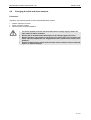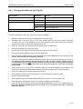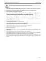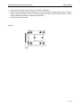
1
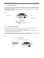
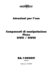
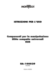
SERVOLINE Handling Components Servo Horizontal Unit SHE Servo Vertical Unit SVE USER MANUAL MECHANICAL PART SHE-130 MECHANICAL PART SVE-130 506920ENG Edition 10/05 H:\610\Automation\Servoline\Mech_Teile\SHE 14.10.2005 Mechanical Part SHE-130 and SVE-130 Edition 10/05 Change index Previously published editions: Edition 05/01 07/03 10/05 Remark First edition, valid from software version 2.00 Page 5-33: Fig. 29 new Page 5-34: additional Pos. 260 Seite 5-39: additional Pos. 30 until Pos. 50, new Fig. 31 Replaced proximity switch Article number 506920 506920ENG 506920ENG I Mechanical Part SHE-130 and SVE-130 Edition 10/05 Table of contents 1. Important information .........................................................................................................................1-1 1.1 Introduction ..................................................................................................................................1-1 1.2 EU conformance (to MRL Appendix II A) ....................................................................................1-1 1.3 Product description and application.............................................................................................1-1 1.4 Dangers .......................................................................................................................................1-1 1.5 Additional information ..................................................................................................................1-2 1.6 Validity of the User Manual....................................................................................................... 1—2 2. Technical data.................................................................................................................................. 2—3 2.1 Servo horizontal unit SHE-130 ................................................................................................. 2—3 2.1.1 Dimensioned drawing of SHE-130 2—4 2.1.2 Load calculations for SHE-130 2—5 2.1.3 Traversing times for SHE-130 2—7 2.2 Servo vertical unit SVE-130...................................................................................................... 2—8 2.2.1 Dimensioned drawing of SVE-130 2—9 2.2.2 Dimensioned drawing of SVE-130-EK 2—10 2.2.3 Load calculations for SVE 2—11 2.2.4 Traversing times for SVE-130 2—12 3. Installation...................................................................................................................................... 3—13 3.1 Mechanical design .................................................................................................................. 3—13 3.1.1 Design of the system 3—13 3.1.2 Installation position and assembly 3—13 3.1.3 Combination of SHE-130 and SVE-130: 3—15 3.2 Leading through cables and hoses from supplementary devices .......................................... 3—15 3.3 Connecting the motor cable and resolver cable ..................................................................... 3—18 3.4 Connecting the inductive proximity switch.............................................................................. 3—19 4. Maintenance .................................................................................................................................. 4—20 4.1 Lubrication .............................................................................................................................. 4—20 4.2 Setting the slide play .............................................................................................................. 4—21 4.3 Changing the inductive proximity switch (460) ....................................................................... 4—22 4.4 Changing the slide and drive elements .................................................................................. 4—23 4.4.1 Changing the ballscrew (30, Fig. 25) 4—24 4.4.2 Changing the clutch (210, Fig. 26) 4—28 4.4.3 Changing rollers (430) and shafts (80) (Fig. 28) 4—30 5. Spare parts .................................................................................................................................... 5—33 5.1 Servo horizontal unit SHE-130 ............................................................................................... 5—33 5.2 Servo vertical unit SVE-130, SVE-130-EK ............................................................................. 5—36 5.3 Spindle assembled ................................................................................................................. 5—39 5.4 Joint assembled...................................................................................................................... 5—40 5.5 Complete energy conducting carrier....................................................................................... 5—41 6. General information ....................................................................................................................... 6—42 6.1 Environmental compatibility and disposal .............................................................................. 6—42 II Mechanical Part SHE-130 and SVE-130 1. Important information 1.1 Introduction Edition 10/05 This operating instruction describes the mechanical design, load limits, assembly, maintenance and spare parts of the Servo Horizontal Unit SHE-130 and of the servo vertical unit SVE-130. It forms an integral part of the operating instruction for the servo amplifier and the operator software. 1.2 EU conformance (to MRL Appendix II A) Regulations and standards taken into account: EU Directive on machines 89/392/EEC, 91/368/EEC Manufacturer: Montech AG Gewerbestrasse 12 CH-4552 Derendingen 1.3 Phone Fax +41 (0) 32 / 681 55 00 +41 (0) 32 / 682 19 77 Product description and application The Servo Horizontal Units SHE-130 and Servo Vertical Units SVE-130 are electrically operated, position-controlled linear units which can be used as individual horizontal or vertical units and in combination as a 2-axis loader. The Servo Horizontal Units SHE-130 can be used exclusively for horizontal movements. Provided that the load limits defined in the technical data are complied with, any devices can be mounted on the servo horizontal units and servo vertical units. 1.4 Dangers The use of servo horizontal units SHE-130 and servo vertical units SVE-130 in equipment is permissible only if they are protected by movable, separating protective devices according to EN 292-2, Section 4.2.2.3. Failure to observe this safety measure can result in injuries due to crushing and impact. The operating conditions and safety notes described in the operating instruction. It is absolutely essential to keep within the stated load limits. Important! Never allow devices to run without mounted covers and hoods. During operation, the surface of the motor can reach 100°C. Do not touch the motor until the temperature has dropped below 40°C (measure the surface temperature). During maintenance work on the servo horizontal unit or on the servo vertical unit, ensure that the power to the drive is switched off. The servo amplifier must be disconnected from the supply voltage. Switch off the main switch or mains contactor. • Switch off the enable signal • Switch off the power supply (L1, L2, L3) • Ensure that no unauthorized switching-on of the supply voltage can occur. Failure to observe these safety measures may result in death or serious personal injuries or material damage. 1-1 Edition 10/05 Mechanical Part SHE-130 and SVE-130 1.5 Additional information The present User Manual is intended to permit proper and safe use of the servo horizontal unit SHE-130 and the servo vertical unit SVE-130. Should you lack any information for your particular application, please contact the manufacturer. When reordering user manuals, it is imperative that you quote the serial number (see Fig. 1). Single copies are provided free of charge. Fig. 1 CH-4552 DERENDINGEN Article number Artikelnummer 49470 GERWERBESTRASSE 12 Type Typ SHE-130-100 102357.002 Serial number Serienummer Montech AG Management U. D. Wagner / A. Trenner 1.6 Validity of the User Manual Our products are continually updated to reflect the latest state of the art and practical experience. In line with product developments, our user manuals are continually updated. To avoid confusion, check that the present User Manual is valid for the servo horizontal unit SHE-130 or servo vertical unit SVE-130 to be commissioned. Every User Manual has an edition number, e.g. 506920 (Fig. 2). The label affixed to the title page shows the product serial number for which the edition number on the User Manual is valid. Fig. 2 Ausgabe-Nummer Edition number Ausgabe-Datum Edition date Article number of User Manual Artikelnummer Betriebsanleitung 05/01 506920 Ausgabe 01 valid for: gültig für: CH-4552 DERENDINGEN 49470 GERWERBESTRASSE 12 SHE-130-100 102357.002 1-2 Mechanical Part SHE-130 and SVE-130 2. Technical data 2.1 Servo horizontal unit SHE-130 Edition 10/05 SHE-130-100 SHE-130-200 SHE-130-300 Max. stroke [mm] 100 200 300 Max. permissible mounting mass [kg] 12 12 12 Max. stat. moment M0Xmax 1) [Nm] 15 15 15 Max. stat. moment M0Ymax 1) [Nm] 65 65 95 Max. stat. moment M0Zmax 1) [Nm] 30 30 45 Max. force FXmax 1) [N] 120 120 120 [mm/s] 1000 1000 1000 [m/s2] 6.5 6.5 6.5 [kg] 5.2 6.2 7.7 Max. speed Max. acceleration 2) Own weight Drive Highly dynamic synchronous servo motor Rated motor power [W] Enclosure protection for servo motor Transmitter system Repeatability Resolver 3) [mm] Reference position proximity switch [dBA] Max. operating temperature of 4) motor [°C] Temperature +/- 0.01 Integrated inductive proximity switch PNP Sound level Ambient conditions 130 IP64 [°C] Rel. humidity Air purity Warranty period Installation position Material < 68 56 10 – 50 5% ... 85% non-condensing Normal workshop atmosphere 2 years from the date of delivery Horizontal Aluminium, steel, plastic 1) See load calculations 2) At max. permissible mounting mass 3) At constant motor temperature. Measured at max. load, max. speed and 100 successive strokes 4) At 20°C ambient temperature, full load and continuous operation 2—3 Edition 10/05 Mechanical Part SHE-130 and SVE-130 2.1.1 Dimensioned drawing of SHE-130 40 74.2 Fig. 3 12.5 27.5 10 30 Ø4H7 7 tief (2x) deep 7 25 50 136 75 (126) 130 4 60 M5 11 tief (4x) deep 11 PG 29 B A max. 184 C 50 40 4 D A max. [mm] B [mm] C [mm] D [mm] SHE-130-100 100 20 - 120 252 532 SHE-130-200 200 20 - 220 352 632 SHE-130-300 300 20 - 320 502 782 2—4 Mechanical Part SHE-130 and SVE-130 Edition 10/05 2.1.2 Load calculations for SHE-130 Fig. 4 a) Dynamic load M X = 0.001 ⋅ m ⋅ g ⋅ LY M Y = 0.001 ⋅ m ⋅ ( g ⋅ ( LX + K X ) + a ⋅ LZ ) M Z = 0.001 ⋅ m ⋅ a ⋅ LY Combined dynamic load: B = MY M + MZ + X ≤ 1 M Yper 28 b) Static load M 0 X = 0.001 ⋅ ( FZ ⋅ LY + FY ⋅ LZ ) M 0Y = 0.001 ⋅ ( FX ⋅ LZ + FZ ⋅ ( LX + K X )) M 0 Z = 0.001 ⋅ ( FX ⋅ LY + FY ⋅ ( LX + K X )) Combined static load: B0 = M 0X M 0Y M 0Z + + ≤ 1 30 M 0Yper 2 ⋅ M 0Zper 2—5 Edition 10/05 Mechanical Part SHE-130 and SVE-130 B, B0: Mi, M0i: Miper, M0iper: m: LX, LY, LZ: FX, FY, FZ: a: KX: Load factor: Must not exceed the value 1! Existing moments [Nm] Permissible moments [Nm] (see Table) Mounting mass [kg] Distance of moving mass from centre of gravity or force application distances [mm] Forces acting [N] Acceleration of the unit [m/s2] Constant according to Table [mm] KX [mm] MXper [Nm] MYper [Nm] MZper [Nm] M0Xper [Nm] M0Yper [Nm] M0Zper [Nm] SHE-130-100 195 10 53 6.5 15 65 30 SHE-130-200 295 10 53 6.5 15 65 30 SHE-130-300 420 10 79 6.5 15 95 45 2—6 Mechanical Part SHE-130 and SVE-130 Edition 10/05 2.1.3 Traversing times of SHE-130 The traversing times were determined for an SHE-130-300 under the following conditions: • Load: 12 kg • Speed: 1000 mm/s • Acceleration or deceleration: 6.5 m/s2 • Beginning of measurement: Start signal at input X11B/2 (Fstart_No.x) • End of measurement: InPosition signal at output X11B/3 (InPos) • InPosition window: 0.01 mm • Low-vibration Quick-Set mounting element A stable, low-vibration mounting element is extremely important for achieving the times according to the graph. Fig. 5 s [mm] 300 200 100 100 200 300 400 500 600 t [ms] s: Traversing distance [mm] t: Time from input of start signal to feedback "In Position" in an "In Position window" of 0.01 mm [ms] 2—7 Edition 10/05 Mechanical Part SHE-130 and SVE-130 2.2 Servo vertical unit SVE-130 Max. stroke [mm] Max. permissible mounting mass [kg] SVE-130-100 SVE-130-200 100 200 5 5 Max. stat. moment M0Xmax 1) [Nm] 30 30 Max. stat. moment M0Ymax 1) [Nm] 65 65 Max. stat. moment M0Zmax 1) [Nm] 15 15 Max. force FZmax 1) [N] 120 120 [mm/s] 1000 1000 [m/s2] 7.5 7.5 [kg] 5.5 6.5 Max. speed max. acceleration 2) Own weight Highly dynamic synchronous servo motor with locking brake Drive Rated motor power [W] Enclosure protection for servo motor 130 IP64 Transmitter system Resolver Repeatability 3) [mm] Reference position proximity switch +/- 0.01 Integrated inductive proximity switch PNP Sound level [dBA] Max. operating temperature of 4) motor [°C] 52 Ambient conditions: [°C] 10 - 50 Temperature Rel. humidity Air purity Warranty period Installation position Material 1) See load calculations 2) At max. permissible mounting mass < 68 5% ... 85% non-condensing Normal workshop atmosphere 2 years from date of delivery Vertical Aluminium, steel, plastic 3) At constant motor temperature. Measured at max. load, max. speed and 100 successive strokes 4) At 20°C ambient temperature 2—8 Mechanical Part SHE-130 and SVE-130 Edition 10/05 2.2.1 Dimensioned drawing of SVE-130 Fig. 6 50 25 4 12.5 85 30 67.5 48.5 M5 11 tief (4x) / deep 11 Ø42 40 75 74.2 27.5 A max. B 4 10 C 50 D 110 240 PG 29 (324) Ø4H7 7 tief (2x) deep 7 22.5 40 50 130 A max. [mm] B [mm] C [mm] D [mm] SVE-130-100 100 20 - 120 252 532 SVE-130-200 200 20 - 220 352 632 2—9 Edition 10/05 Mechanical Part SHE-130 and SVE-130 2.2.2 Dimensioned drawing of SVE-130-EK Fig. 7 12.5 30 4 50 25 M5 11 tief (4x) / deep 11 deep 7 / Ø4H7 7 tief (2x) 136 B 4 10 C D (62.5) 75 27.5 74.2 40 A max. 40 50 130 A max. [mm] B [mm] C [mm] D [mm] SVE-130-100-EK 100 20 - 120 252 532 SVE-130-200-EK 200 20 - 220 352 632 2—10 Mechanical Part SHE-130 and SVE-130 Edition 10/05 2.2.3 Load calculations for SVE Fig. 8 a) Dynamic load M X = 0.001 ⋅ m ⋅ LY ⋅ ( g + a ) M Y = 0.001 ⋅ m ⋅ LX ⋅ ( g + a) Combined dynamic load: B= M X MY + ≤1 10 20 b) Static load M 0 X = 0.001 ⋅ ( FZ ⋅ LY + FY ⋅ ( LZ + K Z )) M 0Y = 0.001 ⋅ ( FZ ⋅ LX + FX ⋅ ( LZ + K Z )) M 0 Z = 0.001 ⋅ ( FX ⋅ LY + FY ⋅ LX ) Combined static load: B0 = M 0 X M 0Y M 0 Z + + ≤1 60 65 30 B, B0: Mi, M0i: Miper, M0iper: m: LX, LY, LZ: FX, FY, FZ: a: KZ: Load factor: Must not exceed the value 1! Existing moments [Nm] Permissible moments [Nm] (see Table) Mounting mass [kg] Distance of moving mass from centre of gravity or force application distances [mm] Forces acting [N] Acceleration of the unit [m/s2] Constant according to Table [mm] KZ [mm] MXper [Nm] MYper [Nm] M0Xper [Nm] M0Yper [Nm] M0Zper [Nm] SVE-130-100 195 10 20 30 65 15 SVE-130-200 295 10 20 30 65 15 2—11 Edition 10/05 Mechanical Part SHE-130 and SVE-130 2.2.4 Traversing times of SVE-130 The traversing times were determined for an SVE-130-200 under the following conditions: • Load: 5 kg • Speed: 1000 mm/s • Acceleration or deceleration: 7.5 m/s2 • Beginning of measurement: Start signal at input X11B/2 (Fstart_No.x) • End of measurement: InPosition signal at output X11B/3 (InPos) • InPositions window: 0.01 mm • Low-vibration Quick-Set mounting element A stable, low-vibration mounting element is extremely important for achieving the times according to the graph. Fig. 9 s [mm] 200 100 100 200 300 400 500 t [ms] s: Traversing distance [mm] t: Time from input of start signal to feedback "In Position" in an "In Position window" of 0.01 mm [ms] 2—12 Mechanical Part SHE-130 and SVE-130 3. Installation 3.1 Mechanical design Edition 10/05 3.1.1 Design of the system When designing the system, the following points must be taken into account: • • • The servo horizontal units SHE-130 and servo vertical units SVE-130 must only be operated behind protective devices according to EN 292-2, Section 4.2.2.3. Ensure unrestricted ventilation of the motor and keep within the permitted ambient temperatures. Provide low-vibration Quick-Set construction. 3.1.2 Installation position and assembly Tool required Dimension Use for: Hexagon socket wrench 4 mm All Quick-Set clamping elements SHE-130: The servo horizontal unit SHE-130 is installed horizontally so that the plug of the servo motor (670) points downwards. Fixing is implemented via the dovetails at the top or bottom of the housing (10) by means of at least two Quick-Set clamping elements SLL-55 (11). The supplementary devices are mounted via the dovetail of the clamping plate (90) with the aid of a clamping element SLL-55 (11) or SLR-15 (12). For greater rigidity, it is advisable to use a clamping element SLL-55 (11) in combination with a clamping element SLL-20 (13) (utilization of the whole dovetail length on the clamping plate (90)). Alternatively, the fixing thread and the positioning holes in the clamping plate (90) can be used (see dimensioned drawing, Fig. 3). Fig. 10 11 11 13 90 10 12 11 11 11 3—13 Edition 10/05 Mechanical Part SHE-130 and SVE-130 SVE-130: The servo vertical unit SVE-130 is installed vertically. Fixing is implemented via the dovetails behind or in front of the housing (10) by means of Quick-Set clamping elements. Depending on the length of the available dovetail on the device or attachment to be installed, at least one clamping element SLL-55 (or SLL55/22) (11) must be used in combination with a clamping element SLL-20 (or SLL-20/22) (13). The supplementary devices are mounted via the dovetail of the clamping plate (90) with the aid of a clamping element SLL-55 (11) or SLR-15 (12). For greater rigidity, it is advisable to use a clamping element SLL-55 (11) in combination with a clamping element SLL-20 (13) (utilization of the whole dovetail length on the clamping plate (90)). Alternatively, the fixing thread and the positioning holes in the clamping plate (90) can be used (see dimensioned drawing, Fig. 6). Fig. 11 11 10 11 13 13 11 90 11 12 3—14 Mechanical Part SHE-130 and SVE-130 Edition 10/05 3.1.3 Combination of SHE-130 and SVE-130: The combination of a servo horizontal unit SHE-130 with a servo vertical unit SVE-130 is implemented by means of an SLL-55/22 and of an SLL-20/22. The increased dovetail space due to the use of these clamping elements permits clean lead-through of the cables and hoses from supplementary devices between the two dovetails (Fig. 12). For stabilizing the protective sleeve of the servo vertical unit SVE-130, it is advisable to fasten the protective sleeve to the cable plugs of the SVE-130 (e.g. by means of a cable tie) (Fig. 13). Fig. 12 Fig. 13 SVE-130 Kabeldurchführung Cable lead-through Fastening Befestigung SHE-130 SLL-20/22 SLL-55/22 3.2 Lead-through of cables and hoses of supplementary devices SHE-130: In the SHE-130, the cables and hoses of the supplementary devices are led by means of the protective sleeve through the upper sleeve opening of the hoods (230 and 240) into the device and out again together with the proximity switch cable (610) through the lower sleeve opening (Fig. 14). A protective sleeve which is fixed in the lower sleeve opening is also used for carrying the cables and hoses further. The motor cable and resolver cable of the SHE-130 are led away along the lower protective sleeve. The motor cable and resolver cable of an installed SVE-130 are led as described under SVE-130 and continue outside the hoods (230 and 240) in the SHE-130 (Fig. 15). Fig. 14 Fig. 15 Schutzschlauch Protective sleeve 240 Motoru.and resolver cable MotorResolverkabel 610 Protective sleeve Schutzschlauch Motor cable Motorkabel Resolverkabel Resolver cable 3—15 Edition 10/05 Mechanical Part SHE-130 and SVE-130 When an energy conducting carrier is used, motor cable and motor resolver cable are led out of the energy conducting carrier according to Fig. 16 and are fastened to the end piece with a cable tie for strain relief. Additional cables and hoses can be laid in the same way as the motor cable and resolver cable or can be led through the SHE-130 into a protective sleeve by removing a connecting link on one of the energy conducting carrier links (in the region of the upper sleeve opening of the hoods (230 and 240)), according to Fig. 14. Fig. 16 Resolver cable Resolverkabel Motor cable Motorkabel End piece Endstück Connecting link Verbindungsbügel 240 Protective sleeve Schutzschlauch 230 SVE-130: The cables and hoses of the supplementary devices are led into the device in the case of the SVE-130 through the opening in the hoods (230 and 240) and additionally covered with the snap-on cable cover (690) (Fig. 17). Together with the proximity switch cable (610), the cables and hoses are led through the sleeve opening into the protective sleeve and continue protected in this way. The motor cable and resolver cable of the SVE-130 are led along the protective sleeve and are fixed to the protective sleeve at some points for stabilization (Fig. 13). 3—16 Mechanical Part SHE-130 and SVE-130 Edition 10/05 Fig. 17 Protective sleeve Schutzschlauch 240 230 690 SVE-130-EK: The cables and hoses of the supplementary devices are led into the energy conducting carrier according to Fig. 18. Motor and resolver cables and the proximity switch cable of the SVE-130-EK are led into the energy conducting carrier by removing one or more connecting links of the energy conducting carrier, as shown in Fig. 18. Fig. 18 Resolver cable Resolverkabel Motor cable Motorkabel Connecting link Verbindungsbügel 3—17 Edition 10/05 Mechanical Part SHE-130 and SVE-130 3.3 Connecting the motor cable and resolver cable • • • • The servo amplifier must be disconnected from the supply voltage. Switch off the main switch or mains contactor. Ensure that no unauthorized switching-on of the supply voltage can occur. During operation, the surface of the motor can reach 100°C. Do not touch the motor until the temperature has dropped below 40°C (measure the surface temperature). Failure to observe these safety measures may result in death or serious personal injuries or material damage. The motor cables and resolver cables supplied are 5 m in length. Longer cables are available as options. The cables are preassembled with coded concentric plugs on the motor side. For easier mounting of the cables on the servo motor (670) the hoods (230 and 240) can be removed by undoing the cap screws (570). Fig. 19 670 240 Motor cable Motorkabel 230 Resolverkabel Resolver cable 3—18 Mechanical Part SHE-130 and SVE-130 3.4 Edition 10/05 Connecting the inductive proximity switch • • • • The servo amplifier must be disconnected from the voltage supply. Switch off the main switch or mains contactor. Ensure that no unauthorized switching-on of the supply voltage can occur. During operation, the surface of the motor can reach 100°C. Do not touch the motor until the temperature has dropped below 40°C (measure the surface temperature). Failure to observe these safety measures may result in death or serious personal injuries or material damage. The length of the proximity switch cable (610) supplied is 5 m. The cable is equipped with a screwable plug on the proximity switch side and is mounted on the proximity switch (460) on delivery. The proximity switch cable (610) is led out through the lower opening (SHE-130) or the protective sleeve connection (SVE-130) of the hoods (230 and 240) and into a protective sleeve. Note: Wiring according to User Manual for servo amplifier. Fig. 20 610 240 460 3—19 Edition 10/05 Mechanical Part SHE-130 and SVE-130 4. Maintenance 4.1 Lubrication Move servo unit to a position ≥ 50 mm and switch off voltage supply. • • • • The servo amplifier must be disconnected from the voltage supply. Switch off the main switch or mains contactor. Ensure that no unauthorized switching-on of the voltage supply can occur. During operation, the surface of the motor can reach 100°C. Do not touch the motor until the temperature has dropped below 40°C (measure the surface temperature). Failure to observe these safety measures may result in death or serious personal injuries or material damage. Use only Klüber oil "Paraliq P460" as a lubricant (Montech Art. No. 504721). • • Lubrication interval: Lubrication points: 800 operating hours 4 lubricating nipples and ballscrew (Fig. 21) Lubrication of the ballscrew: • • • • • Remove hood (230). Apply Paraliq P460 directly to the ballscrew (30) over the whole area of the elliptical hole in the housing (10). Mount hood (230). Connect supply voltage and switch on. Start reference traverse. Fig. 21 Lubricating nipple Schmiernippel Schmiernippel Lubricating nipple Lubricating nipple Schmiernippel 10 Lubricating nipple Schmiernippel Kugelumlaufspindel Ballscrew • Do not start servo units without mounted hoods (230 and 240)! 4—20 Mechanical Part SHE-130 and SVE-130 4.2 Setting the slide play • • • • The servo amplifier must be disconnected from the voltage supply. Switch off the main switch or mains contactor. Ensure that no unauthorized switching-on of the supply voltage can occur. During operation, the surface of the motor can reach 100°C. Do not touch the motor after the temperature has dropped below 40°C (measure the surface temperature). Failure to observe these safety measures may result in death or serious personal injuries or material damage. Tool required Dimension 2 screwdrivers No. 6 • • • Edition 10/05 Use for: Items 190; 170 Undo the two upper threaded journals (190) so that the tension nuts (170) can be easily turned with the eccentric shafts (160). By turning the tension nuts (170) clockwise, set the rollers (430) so that there is no play (no initial tension). Tighten the threaded journals (190) while holding the tension nuts (170) with a screwdriver to prevent the set position of the roller (430) from changing. Fig. 22 170 430 430 170 190 160 160 190 4—21 Edition 10/05 Mechanical Part SHE-130 and SVE-130 4.3 Changing the inductive proximity switch (460) • • • • The servo amplifier must be disconnected from the voltage supply. Switch off the main switch or mains contactor. Ensure that no unauthorized switching-on of the supply voltage can occur. During operation, the surface of the motor can reach 100°C. Do not touch the motor until the temperature has dropped below 40°C (measure the surface temperature). Failure to observe these safety measures may result in death or serious personal injuries or material damage. Tool required Hexagon socket wrench • • • • • • • Dimension Use for: 2.5 mm Item 500 4 mm Item 570 Move hood (230) by undoing the cap screws (570). Disconnect cable (610) from proximity switch (460). Undo screw (500) and remove proximity switch (460). Mount the new proximity switch (460) on the housing flange (40) (use thread on output side of proximity switch (460) and mount proximity switch (460) so that it rests on the base of the groove). Mount cable (610) to proximity switch (460). Mount hood (230). The LED of the proximity switch (460) must light up when supply voltage is applied if the slide (20) is completely retracted. When this condition is fulfilled, the reference traverse can be implemented. Note: Proximity switch PNP, switching distance 2 mm (also see Spare Parts List) Fig. 23 610 500 460 40 4—22 Mechanical Part SHE-130 and SVE-130 4.4 Edition 10/05 Changing the slide and drive elements Procedure: Important: The following points must be implemented before repairs: • • • Perform reference traverse. Switch off supply voltage. Remove servo unit from installation. • • • • The servo amplifier must be disconnected from the voltage supply. Switch off main switch or mains contactor. Ensure that no unauthorized switching-on of the voltage supply can occur. During operation, the surface of the motor can reach 100°C. Do not touch the motor until the temperature has dropped below 40°C (measure the surface temperature). Failure to observe these safety measures may result in death or serious personal injuries or material damage. 4—23 Edition 10/05 Mechanical Part SHE-130 and SVE-130 4.4.1 Changing the ballscrew (30) (Fig. 25) Tool required Dimension Use for: Fork spanner 13 mm Item 30 Hook spanner 21 mm Item 420 Hexagon socket wrench 2.5 mm Items 500; 210 3 mm Items 540; 510 4 mm Items 570; 560; 550 Art. No. 49466 Orientation of the spindle Assembly gauge Procedure (Preparation and notes, page C23, must be consulted): • Remove hoods (230 and 240) by unscrewing the cap screws (570). • The slide (20) of the servo unit is in the zero position after the reference traverse (dimension x = 20 mm, Fig. 24). The threaded pins of the clutch (210) are visible in the lateral hole (A) and the gap (B) on the surface of the motor flange (50) (Fig. 26). • Undo cap screw (500) and remove proximity switch (460) incl. cable (610). • Undo both threaded pins in the clutch (210). • Unscrew cap screws (560) and remove servo motor (670) incl. clutch (210). • Unscrew cap screws (550a) and remove motor flange (50). • Undo cap screws (550b) and pull away housing flange (40) max. 80 mm from the housing (10). Important: Slide (20) must be completely retracted. • Undo cap screws (540) and withdraw assembled spindle (30) incl. housing flange (40) from the servo unit. Important: The revolving nut with the joint (C) may not move from the spindle. Hold revolving nut with joint (C) and spindle so that the joint (C) with the revolving nut cannot move on the spindle. The revolving nut moves very easily and moves by itself with a small approach angle. • Secure joint (C) incl. revolving nut by applying cable ties around the spindle, on both sides of the revolving nut (width across flats between joint (C) and housing flange (40) must be accessible). • Undo cap screws (510) and remove bearing cover (60). • Undo slotted nut (420) (hold with fork spanner on flats of ballscrew (30)) and remove. • Remove spacer sleeve (200). • Push ballscrew (30) out of the self-aligning ball bearing (410) in the housing flange (40). • Push self-aligning ball bearing (410) out of the housing flange (40) and replace. • Push new ball screw (30) incl. joint into the self-aligning ball bearing (410) in the housing flange (40). Important: Ensure beforehand that the revolving nut on the spindle has been secured by means of cable ties. 4—24 Mechanical Part SHE-130 and SVE-130 Edition 10/05 No forces may act on the revolving nut of the spindle and on the joint. • Push spacer sleeve (200) onto ball screw (30) and screw on slotted nut (420) and tighten. (Hold with fork spanner on flats of the ballscrew (30)). • Mount bearing cover (60) and tighten cap screws (510) uniformly in a crosswise manner. • Remove cable ties (for securing revolving nut). • Move ballscrew (30) into slide (20). Important: Hold revolving nut with joint (C) and spindle so that the joint (C) with the revolving nut cannot move on the spindle. The revolving nut moves very easily and may move by itself simply with a small angle of approach. • Screw joint (C) to slide (20) (note position of the joint: cap screw (D) must be on the operating side). Important: Distance between joint and housing flange (40) is not more than 80 mm. • Push housing flange (40) onto housing (10) and screw in cap screws (550b) (do not tighten, note position of proximity switch clearance). • Mount motor flange (50) (note position). • Position slide (20) at dimension x = 20 mm (Fig. 24). • Push assembly gauge (Art. No. 49466) onto the end of the ballscrew (30) and position by moving the housing flange (40) in the turned hole in the motor flange (50). • Fasten assembly gauge by means of cap screws (560) to motor flange (50). • Tighten cap screws (550b) to fasten the housing flange (40). • Remove assembly gauge. • Mount servo motor (670) incl. clutch (210). Important: Note position of the threaded pin in the clutch (210). • Mount servo motor by means of cap screws (560) on motor flange (50). • Tighten both threaded pins in the clutch (210) through the gaps in the motor flange (50). Important: Before tightening, check the slide position (dimension x = 20 mm, Fig. 24). • Mount the proximity switch (460) incl. cable (610) on the housing flange (40) (use thread on cable side in proximity switch (460) and mount proximity switch (460) so that it rests on the bottom of the groove). 4—25 Mechanical Part SHE-130 and SVE-130 Edition 10/05 • Lubricate the ballscrew (30) according to the section "Lubrication". • Mount hoods (230 and 240) (lead cable (610) out through appropriate opening (see section "Connecting the inductive proximity switch") and lead through any cable and hoses (see section "Leading through cables and hoses from supplementary devices)). • Check the reference positions. Fig. 24 x 4—26 20 D 40 540 500 540 10 30 230 420 460 610 550b 550b 200 550b 550b 540 570 570 540 410 C 550a 60 550a 550a 510 670 210 510 550a 50 510 560 510 560 560 570 560 240 570 Mechanical Part SHE-130 and SVE-130 Edition 10/05 Fig. 25 4—27 Edition 10/05 Mechanical Part SHE-130 and SVE-130 4.4.2 Changing the clutch (210, Fig. 26) Tool required Hexagon socket wrench Dimension 2.5 mm 4 mm Use for: Item 210 Items 570; 560 Procedure (Preparations and notes, page C23, must be consulted): • Remove hoods (230 and 240) by unscrewing the cap screws (570). • After the reference traverse, the slide (20) of the servo unit is in the zero position (dimension x = 20 mm, Fig. 24). The threaded pins of the clutch (210) are visible in the lateral hole (A) and the gap (B) at the top of the motor flange (50). • Undo both threaded pins in the clutch (210). • Unscrew cap screws (560) and remove servo motor (670) incl. clutch (210). • Mark position of the threaded pins in the clutch (210) on the servo motor (670). • Undo both threaded pins in the clutch (210) on the motor side and remove clutch (210). Important: In the servo motor (670) without a brake, ensure that the motor shaft is not turned. • Push new clutch (210) onto motor shaft. Before pushing on, align the clutch with the markings (no rotation of the motor shaft). Distance between motor and clutch: 3 mm (Fig. 27). • Tighten both threaded pins in the clutch (210) on the motor side. • Mount servo motor (670) incl. clutch (210) on motor flange (50) (note position of servo motor (670) and clutch (210); slide (20) must be in the zero position (dimension x = 20 mm, Fig. 24)). • Tighten both threaded pins in the clutch (210) through the gaps (A and B) in the motor flange (50). • Mount hoods (230 and 240) (lead cable (610) through appropriate opening (see section "Connecting the inductive proximity switch") and lead through any cables and hoses (see section "Leading through cables and hoses from supplementary devices")). • Check the reference positions. 4—28 Mechanical Part SHE-130 and SVE-130 Edition 10/05 Fig. 26 570 610 570 B 240 A 50 210 560 570 560 560 670 230 560 570 Fig. 27 210 670 3 4—29 Edition 10/05 Mechanical Part SHE-130 and SVE-130 4.4.3 Changing the rollers (430) and shafts (80) (Fig. 28) The shafts (80) must always be changed together with the associated rollers (430). Tool required Hexagon socket wrench 2 screwdrivers Dimension Use for: 2 mm Item 590 3 mm Items 520; 580 4 mm Items 570; 550 No. 6 Items 190; 150; 160; 170; 180 Procedure (Preparations and notes, page C23, must be consulted). • Remove hoods (230 and 240) by unscrewing the cap screws (570). • Remove proximity switch cable (610). • Remove clamping plate (90) by undoing the cap screws (520). • Unscrew cap screws (580) in the end plate (70) by 5 – 6 mm each. • Undo cap screws (550b) and pull housing flange (40) incl. servo motor (670), ballscrew (30) and slide (20) out of the housing (10) (hold servo motor (670) and slide (20)). • Push felt wick (140) back into end plate (70). • Withdraw shaft (80) from the grooves in the slide (20) and replace. • Remove cover (220) from housing (10) by undoing the cap screws (590). • Unscrew threaded journal (190a). • Undo tension nuts (180) and remove. • Remove rollers (430) by pushing out the concentric shafts (150). • Insert new rollers (430) and push in concentric shafts (150). • Tighten tension nuts (180) (hold the concentric shafts (150)). • Screw in threaded journal (190a) and tighten. • Unscrew threaded journal (190b). • Undo tension nuts (170) and remove. • Remove rollers (430) by pushing out the eccentric shafts (160). • Insert new rollers (430) and push in eccentric shafts (160). • Tighten tension units (170) (hold the eccentric shafts (160)). • Screw in threaded journal (190b) (tighten only lightly). • Set maximum distances between the upper and lower rollers (430) by turning the tension nuts (170). 4—30 Mechanical Part SHE-130 and SVE-130 • Edition 10/05 Push slide (20) incl. ballscrew (30), housing flange (40) and servo motor (670) into the housing (10) while holding the servo motor (670) and slide (20) and position the lower shaft (80) relative to the tightened rollers (430) (note felt (130) in the case of the rear rollers (430)). Important: Note position of slide (20), housing flange (40) and servo motor (670). • Screw in cap screws (550b) (screw in only lightly, do not tighten). • By turning the tension nut (170) clockwise, set the rollers (430) without any play (without initial tension). • Tighten threaded journal (190b) while holding the tension nut (170) with a screwdriver so that the set position of the roller (430) does not change. • Tighten cap screws (550b) (slide (20) fully retracted). • Mount cover (220). • Screw in cap screws (550) fully (felt wick (140) must touch the shafts (80)). • Mount clamping plate (90) (note position: slot A on the side of the eccentric shafts (160)). • Mount proximity switch cable (610). • Mount hoods (230 and 240) (possibly after mounting in the installation (-> cable lead-through)). • Before putting into operation again, relubricate according to section "Lubrication". • Check the reference positions. 4—31 A 140 140 160 580 580 590 220 590 190a 150 190a 150 190b 190b 520 70 160 520 520 90 520 430 430 30 20 430 80 570 170 430 180 170 570 230 80 180 10 130 40 610 550b 550b 550b 550b 670 240 570 570 Mechanical Part SHE-130 and SVE-130 Edition 10/05 Fig. 28 4—32 80 90 640 640 520 520 640 640 520 520 530 530 650 530 80 650 600 580 10 30 130 120 110 640 640 540 540 640 540 540 410 500 420 50 240 450 190 590 220 590 640 640 540 540 660 660 550 550 100 160 40 160 150 190 100 450 190 150 190 640 440 140 450 450 400 400 110 640 540 640 540 430 470 180 470 430 430 180 170 690 510 640 510 640 660 60 460 640 510 610 510 640 680 660 550 660 210 550 550 660 550 660 620 570 250 660 230 660 570 670 560 660 560 660 560 660 560 660 Servo horizontal unit SHE-130 140 440 600 580 430 130 120 250 5.1 530 70 540 170 570 Spare parts 650 650 20 640 260 550 550 660 660 200 660 5. 630 90 640 640 540 540 SHE-130-300 620 570 Mechanical Part SHE-130 and SVE-130 Edition 10/05 Fig. 29 5—33 Edition 10/05 Mechanical Part SHE-130 and SVE-130 Spare parts list for SHE-130 (Fig. 29) Item Designation Item number SHE-130- -100 -200 -300 10 Housing 49244 49376 49377 20 Slide 49245 49378 49379 Montech AG Aluminium 30 Spindle assembled 49467 49468 49469 Montech AG Various 40 Housing flange 49218 Montech AG Aluminium 50 Motor flange 49219 Montech AG Aluminium 60 Bearing cover 49220 Montech AG Aluminium 70 End plate 80 Shaft 90 Clamping plate 100 110 Supplier Material Montech AG Aluminium Strokeindependent 49211 Montech AG Aluminium Montech AG Steel 49217 Montech AG Aluminium Lubricating tube 49212 Montech AG Aluminium Buffer holder 49213 Montech AG Aluminium 49388 49389 49390 120 Felt holder 49221 Montech AG POM 130 Felt 49222 Montech AG Wool felt 140 Felt wick 40921 Montech AG Wool felt 150 Concentric shaft 49223 Montech AG Steel 160 Eccentric shaft 49224 Montech AG Steel 170 Tension nut 49225 Montech AG Steel 180 Tension nut 49226 Montech AG Steel 190 Threaded journal 49227 Montech AG Steel 200 Spacer sleeve 49228 Montech AG Steel 210 Clutch 506919 Montech AG Various 220 Cover 50027 Montech AG Painted ABS 230 Hood right 49906 Montech AG Painted ABS 240 Hood left 49907 Montech AG Painted ABS 250 Ellipse 260 Supporting tube 400 Plug-in buffer 506160 410 Self-aligning ball bearing 2201 2RS 503611 420 Slotted nut M12x1 BN 1235 505245 430 Roller 503663 INA Steel 440 Pressure spring 504119 Kubo Tech AG Steel 450 Lubricating nipple 504554 Hausammann AG Brass 460 Proximity switch PNP 508847 Contrinex Various 470 Set nut BN 201 M4 h1=1.8 502615 Bossard AG Steel 49360 - - 51228 Montech AG PS Montech AG Steel / POM Maag Technik AG NR Steel Bossard AG Steel, PA 500 Socket head cap screw ISO 4762 M3x8-8.8 501603 Blackened steel 510 Socket head cap screw ISO 4762 M4x12-8.8 501620 Blackened steel 520 Socket head cap screw ISO 4762 M4x16-8.8 501622 Blackened steel 530 Socket head cap screw ISO 4762 M4x16-A4 505328 Stainless steel 540 Socket head cap screw ISO 4762 M4x20-8.8 501624 Blackened steel 550 Socket head cap screw ISO 4762 M5x14-8.8 501639 Blackened steel 560 Socket head cap screw ISO 4762 M5x18-8.8 501641 Blackened steel 570 Socket head cap screw ISO 4762 M5x25-A4 505192 Stainless steel 580 Cap screw BN 1206 M6x10-10.9 506798 Bossard AG Nickel-plated steel 5—34 Mechanical Part SHE-130 and SVE-130 Item Designation Item number SHE-130- -100 -200 Edition 10/05 Supplier -300 Material Strokeindependent 590 Cap screw BN 1206 M4x6-10.9 506799 Bossard AG Nickel-plated steel 600 Screw seal 506185 Angst+Pfister AG Steel, PUR 610 Cable 504610 Montech AG PUR 620 Montech logo 41176 Montech AG PVC 630 Type plate 41620 Montech AG Metallized polyester 640 Ribbed washer M4 502364 Bossard AG Blackened steel 650 Ribbed washer M4 502606 Bossard AG Galvanized steel 660 Ribbed washer M5 502365 Bossard AG Blackened steel 670 Servo motor 506784 Kollmorgen Seidel Various 680 Protective sleeve 503693 PMA Elektro AG PA 690 Cap 504784 Maag Technik AG PA 5—35 90 640 640 520 520 640 640 520 520 530 80 530 630 530 650 530 650 650 20 70 80 650 600 580 140 440 600 580 540 540 40 50 190 450 160 100 590 220 590 690 (SVE-130) 640 640 540 540 660 660 550 550 160 150 190 100 450 190 150 190 440 140 450 450 400 400 110 640 540 640 540 130 610 510 640 60 460 660 550 660 210 550 550 560 660 560 660 560 660 560 660 230 (SVE-130-EK) 660 570 250 660 570 620 680 (SVE-130) 670 (SVE-130) 230 (SVE-130) 670 (SVE-130-EK) 660 550 660 640 640 510 640 510 640 240 410 130 120 110 640 640 540 540 640 660 500 30 250 430 10 570 180 470 430 430 470 180 170 550 550 660 660 200 660 510 120 570 420 430 170 620 5.2 240 (SVE-130-EK) 690 (SVE-130-EK) Mechanical Part SHE-130 and SVE-130 Edition 10/05 Servo vertical unit SVE-130, SVE-130-EK Fig. 30 5—36 Mechanical Part SHE-130 and SVE-130 Edition 10/05 Spare parts list for SVE-130, SVE-130-EK (Fig. 30) Item Designation Item number SVE-130 / SVE-130-EK -100 -200 10 Housing 49244 20 Slide 30 Spindle assembled 40 Housing flange 50 Motor flange 49219 Montech AG Aluminium 60 Bearing cover 49220 Montech AG Aluminium 70 End plate 49211 Montech AG Aluminium 80 Shaft Montech AG Steel 90 Clamping plate 49217 Montech AG Aluminium 100 Lubricating tube 49212 Montech AG Aluminium 110 Buffer holder 49213 Montech AG Aluminium 120 Felt holder 49221 Montech AG POM 130 Felt 49222 Montech AG Wool felt 140 Felt wick 40921 Montech AG Wool felt 150 Concentric shaft 49223 Montech AG Steel 160 Eccentric shaft 49224 Montech AG Steel 170 Tension nut 49225 Montech AG Steel 180 Tension nut 49226 Montech AG Steel 190 Threaded journal 49227 Montech AG Steel 200 Spacer sleeve 49228 Montech AG Steel 210 Clutch 506919 Montech AG Various 220 Cover 50027 Montech AG Painted ABS 230 240 250 Supplier Material 49376 Montech AG Aluminium 49245 49378 Montech AG Aluminium 49467 49468 Montech AG Various Montech AG Aluminium Strokeindependent 49218 49388 49389 Hood right SVE-130 49908 Montech AG Painted ABS Hood right SVE-130-EK 49592 Montech AG Painted ABS Hood left SVE-130 49909 Montech AG Painted ABS Hood left SVE-130-EK 49593 Montech AG Painted ABS Ellipse 49360 Montech AG PS Maag Technik AG 400 Plug-in buffer 506160 410 Self-aligning ball bearing 2201 2RS 503611 NR Steel 420 Slotted nut M12x1 BN 1235 505245 Bossard AG Steel, PA 430 Roller 503663 INA Steel 440 Pressure spring 504119 Kubo Tech AG Steel 450 Lubricating nipple 504554 Hausammann AG Brass 460 Proximity switch PNP 508847 Contrinex Various 470 Set nut BN 201 M4 h1=1.8 502615 Bossard AG Steel 500 Socket head cap screw ISO 4762 M3x8-8.8 501603 Blackened steel 510 Socket head cap screw ISO 4762 M4x12-8.8 501620 Blackened steel 520 Socket head cap screw ISO 4762 M4x16-8.8 501622 Blackened steel 530 Socket head cap screw ISO 4762 M4x16-A4 505328 Stainless steel 540 Socket head cap screw ISO 4762 M4x20-8.8 501624 Blackened steel 550 Socket head cap screw ISO 4762 M5x14-8.8 501639 Blackened steel 560 Socket head cap screw ISO 4762 M5x18-8.8 501641 Blackened steel 570 Socket head cap screw ISO 4762 M5x25-A4 505192 Stainless steel 5—37 Edition 10/05 Mechanical Part SHE-130 and SVE-130 Item Designation Item number SVE-130 / SVE-130-EK -100 -200 Supplier Material Strokeindependent 580 Cap screw BN 1206 M6x10-10.9 506798 Bossard AG Nickel-plated steel 590 Cap screw BN 1206 M4x6-10.9 506799 Bossard AG Nickel-plated steel 600 Screw seal 506185 Angst+Pfister AG Steel, PUR 610 Cable 504610 Montech AG PUR 620 Montech logo 41176 Montech AG PVC 630 Type plate 41620 Montech AG Metallized polyester 640 Ribbed washer M4 502364 Bossard AG Blackened steel 650 Ribbed washer M4 502606 Bossard AG Galvanized steel 660 Ribbed washer M5 502365 Bossard AG Blackened steel 670 680 690 Servo motor SVE-130 506772 Kollmorgen Seidel Various Servo motor SVE-130-EK 507035 Kollmorgen Seidel Various Protective sleeve (SVE-130 only) 503693 PMA Elektro AG PA Cable cover SVE-130 49543 Montech AG Aluminium Cap SVE-130-EK 504784 Maag Technik AG PA 5—38 Mechanical Part SHE-130 and SVE-130 5.3 Edition 10/05 Spindle assembled Item Designation Item number SHE-130 / SVE-130 -100 -200 -300 Spindle assembled 49467 49468 49469 Montech AG Various 49385 49386 49387 Montech AG Various 51227 Montech AG Steel Montech AG 10 Joint assembled 20 Ballscrew 30 Adjustment screw Supplier Strokeindependent 49475 - - 40 Centering sleeve - - 50393 50 Needle roller bearing without inner ring HK1012 - - 507948 Material POM Steel Fig. 31 30 40 50 20 10 5—39 Edition 10/05 Mechanical Part SHE-130 and SVE-130 5.4 Item Joint assembled Designation Item No. Joint assembled 49475 Sleeve 20 30 40 Straight pin DIN 6325 ø4h6x16 502036 Steel 50 Straight pin DIN 6325 ø4h6x20 502038 Steel 60 Plug-in buffer 506160 70 Socket head cap screw ISO 4762 M4x6-8.8 501617 Steel 80 U-washer ISO 7092 ø4.3/8x0.5 502569 Steel 10 Supplier Material 49216 Montech AG Aluminium Joint ring 49214 Montech AG Bronze Flange 49215 Montech AG Aluminium Maag Technik AG NR Fig. 32 10 80 70 50 30 20 40 60 60 40 50 5—40 Mechanical Part SHE-130 and SVE-130 5.5 Edition 10/05 Energy conducting carrier complete Item Designation Item No. Supplier Energy conducting carrier complete 49901; 49902; 49903 Material 10 Adapter, straight 49899 Montech AG Aluminium 20 Driver connection EK 48994 Montech AG PA 30 Energy conducting carrier link 0345.030.038.075 507037 Kabelschlepp PA 40 Clamping element SLL-55-40 40201N Montech AG Aluminium, steel 50 Socket head cap screw ISO 4762 M5x16-8.8 501640 Steel 60 U-washer ISO 7092 ø5.3/10x1 502416 Steel Fig. 33 40 10 30 60 60 50 20 60 50 60 50 50 60 60 20 60 60 10 40 5—41 Mechanical Part SHE-130 and SVE-130 6. General information 6.1 Environmental compatibility and disposal Edition 10/05 Materials used • • • • • • • • • • • • Aluminium Steel Brass Bronze Wool fibres PUR Polyurethane PA Polyamide POM Polyoxymethylene ABS Acrylonitrile-butadiene/styrene PS Polystyrene NR Natural rubber PVC Polyvinyl chloride Surface finish • • • Anodic oxidation of aluminium Blackening of steel Coating of ABS Shaping processes • • • • Extrusion of aluminum profiles Machining of metals and plastics Injection moulding of plastics Foaming of plastics Emissions during operation • None Disposal Servo horizontal units (SHE-130) or servo vertical units (SVE-130) that are no longer in use are to be dismantled and recycled according to the type of material. The type of material for each part is stated in the spare parts lists. Any non-recyclable material is to be disposed of properly according to materials. 6—42