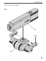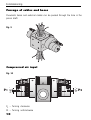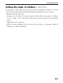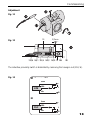
1
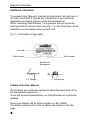
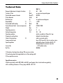
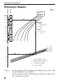
Handling Components
OPERATING INSTRUCTIONS
Rotary Units:
DAP-3
Issue:
BA-100024
02/2006
Contents
Important information
EU Certificate of Conformity (CE) ...........................................1
Scope of the instructions........................................................2
Technical data......................................................................3
Performance diagram ...........................................................4
Pressure-torque diagram .......................................................5
Commissioning
Mounting position.................................................................6
Mounting .............................................................................7
Mounting moving bodies on the axis of rotation ......................8
Passage of cables and hoses ...............................................10
Input of compressed air.......................................................10
Adjusting the angle of rotation.............................................11
Adjusting the shock-absorbers .............................................12
Adjusting and connecting the inductive proximity switches .....12
Technical data of MONTECH standard components ..............14
Formulas for calculating moments of inertia ..........................16
Maintenance
Inspecting the shock-absorbers ............................................17
Lubrication .........................................................................17
Spare parts lists
DAP-3 ...............................................................................18
Suppliers and list of materials ..............................................20
General notes
Environmental compatibility and disposal .............................22
Important Information
EU Certificate of conformity (as per MRL Appendix II A)
Regulations and standards taken into account:
• Guidelines for machines 89/392/ECC, 91/368/ECC
Manufacturer
Montech AG
Gewerbestrasse 12
CH-4552 Derendingen
Tel. 032 / 681 55 00
Fax. 032 / 682 19 77
Description of product and use
Rotary drives DAP-3 are used where ever regularly rotating movements forwards
and backwards have to be performed.
Under all circumstances the performance limits quoted in the technical data have to
be taken into account.
With freely rotating masses particular attention must be paid to the mass moment
of inertia.
Risks
The actuation of freely rotating masses with rotary drives DAP-3 is only permissible
when it is safeguarded by MOVING, ISOLATING PROTECTIVE DEVICES in accordance with EN 292-2, para 4.2.2.3.
The cover (Fig. 20; item 130) may only be removed to carry out adjustments and
lubrication (danger of contusion injury). In automatic operation never work without
the cover fitted.
1
Important Information
Additional information
The present User Manual is intended to allow proper and safe use of
the rotary drive DAP-3. Should any information for your particular
application be missing, please contact the manufacturer.
When reordering User Manuals, it is imperative that you quote the
slide type and the serial number (see Fig. 1-1). This document can be
ordered on our homepage www.montech.com.
Fig. 1-1: Description of type plate
Bar code
45055
Order number
Serial number
Montech AG
Management
U. D. Wagner
C. Wullschleger
Validity of the User Manual
Our products are continually updated to reflect the latest state of the
art and practical experience.
In line with product developments, our User Manuals are continually
updated.
Every User Manual has an article number e.g. BA-100020.
The article number and the date of edition are evident on the title
page.
2
Important Information
Technical Data
Range of adjustment of angle of rotation
Torque at 5 bar
Permissible moment of inertia
Piston diameter
Rotation time
Repeatability
1)
Permissible shaft loading
2)
Permissible axial load tension/compression
Weight
Operating pressure
Ambient temperature
Operating medium
Damping in end positions
Check of end positions
3)
Compressed air input
Speed regulation
(°)
(Nm)
(kgcm2)
(mm)
(s)
(°)
(Nm)
(N)
(kg)
(bar)
(°C)
Service life
Ref. No.
DAP-3
60 … 180
see pressure-torque diagram
30'000
60
see performance diagram
≤ 0.02
100
3'000/5'000
11
2…6
10 … 50
oiled or unoiled air, filtered to 5 µm
hydraulic shock-absorbers
induct. proximity switch
hose 4 ID/6 mm O.D. dia. to push-on union
adjustable exhaust throttles with R 1/8"
thread and push-on union 6 mm dia.
> 107 double strokes
45055
1) Variation of end positions during 100 successive strokes
2) Load acting about the longitudinal axis of the rotating shaft
3) See special accessories
Special accessories
Inductive proximity switch PNP, M8x1 with LED, proof against short circuit and wrong polarity,
with a switching clearance of 2 mm, plug-in Ref.No. 505 118.
3
Important Information
30000
25000
20000
15
15000
20
10000
25
5000
4000
30
Exemple:
Beispiel:
JJ
2
== 15'000
15'000kgcm
kgcm2
== 120°
120°
p
bar
p == 55bar
3000
35
Results:
Resultate:
2000
nmax = 20 min.-1-1
1500
tt
1000
Fig. 3
= 180°
= 150°
= 60°
= 90°
= 120°
n [1/min]
J [kgcm2]
Performance diagram *
nmax = 20 min.
= 0.74
=
0,74ss
40
t [s]
500
400
p = 2 bar
p = 3 bar
p = 4 bar
p = 5 bar
p = 6 bar
2,0
1,5
1,0
0,5
0,4
0,3
0,2
0,1
J = Massenträgheitsmoment
Anzahl of
Doppelhübe
Jn == max.
Mass moment
inertia
p
=
pneum.
Antriebsdruck
n = Max. number double strokes
t = Verfahrzeit pro Hub
p = Pneumatic op. pressure
= Drehwinkel
t = Travel time per stroke
= Angle of rotation
* Scope: – Centre of gravity of the rotating mass located on the axis of rotation, which may be in any position.
– Centre of gravity of the rotating mass off set from the axis of rotation, with the axis vertical.
4
Important Information
Pressure-torque diagram
Fig. 4
p [bar]
2)
6
1)
5
4
3
2
p
10
20
30
40
50
60
70 M [Nm]
= Pneumatic operating pressure
MH = Holding torque; corresponds to that which can be externally applied to
the stationary pinion shaft, without it moving.
MB = Moving torque; corresponds to that made available by the pneumatic
drive at the rotating pinion shaft.
DAP left-hand/right-hand end position
P
MH = p * 6.917
1)
MB = p * 6.0
2)
MH MB
5
Commissioning
Mounting position
In principle, the rotary units may be mounted in any position. But it should be
borne in mind that when the axis of rotation is not vertical and the centre of
gravity of the mass is eccentric with respect to the axis of rotation, additional
variable torques are likely to occur. They may be either in the direction of rotation or in the opposite direction. The result is that the permissible mass moment
of inertia has to be reduced from 30'000 kgcm2 and that the time (t) shown in
the performance diagram (Fig.3) becomes longer owing to the speed being
reduced.
Fig. 5
6
Commissioning
Mounting
The rotary unit DAP-3 is mounted either by means of four M8 fixing holes on
two sides of the housing, or with an adaptor plate (Ref.No. 45338) to any
available QUICK-SET dovetail.
With the MONTECH Quick-Set components mounting structures can be constructed quickly and easily.
Any correction to the position of the rotary unit (displacement of the axis) determines which of the four methods of mounting is most suitable.
Fig. 6
SLL-55
Adaptor
plate
Adapterplatte
DAP-3/QSB
DAP-3/QSB
M8
ø 12-H7
DAP-3
4
18
7
Commissioning
Mounting moving bodies on the rotating axis
Mounting with QUICK-SET-supporting profiles
Fig. 7
TP-16
TP-66
SLR-24
DAP-3
8
Commissioning
Linear unit attached by SRL 24
Fig. 8
LEP
SLR-24
DAP-3
9
Commissioning
Passage of cables and hoses
Pneumatic hoses and external cables can be passed through the hole in the
pinion shaft.
Fig. 9
Compressed air input
P1 … Turning clockwise
P2 … Turning anticlockwise
10
R 18"
P1
R 18"
Fig. 10
P2
Commissioning
Setting the angle of rotation (see Fig.20)
The angle of rotation has to be set using a very low speed of rotation. The nonreturn throttle valves (440) therefore should be opened by only 2-3 turns.
• Release the lock-nut (170).
• Turning one or both of the stop bushes (120) alters the angle of rotation
(1 turn = appr. 3.5°). The stop bushes may only be moved in the unloaded
state.
• Tighten the lock-nut (170).
•When the stop bushes (120) are turned back fully, a maximum angle of
rotation of 180 is obtained.
11
Commissioning
Setting the shock-absorbers (see Fig.20)
The speed of travel, the mass moment of inertia, the operating pressure and, in
certain cases, the position of the axis of rotation, influence the amount of energy to be absorbed by the shock-absorbers. The optimum setting of the shockabsorbers, i.e. that which results in the shortest travel time for given variables,
is obtained as follows.
• Mount the rotary unit in the desired position.
• From the fully closed position open the non-return throttle valves (440) about
2-3 turns.
• Release the lock-nut of the shock-absorber.
• Screw the shock-absorber (220) into the stop bush (120) until the set angle of
rotation ø begins to decrease.
• Increase the speed of travel by opening the non-return throttle valve (440)
until the rotating mass moves into the appropriate end position apparently
with constant speed, without causing any impact.
If this point is not attained, even with the throttle fully open, i.e. if a reduction
in speed is apparent just before the end position is reached, the shock-absorber must be slowly turned back until the end position is approached without
any apparent speed reduction.
In rooms with fluctuating ambient temperature this setting must be carried out
at the highest temperature that occurs.
• Tighten the lock-nut of the shock-absorber.
Setting and connecting the inductive proximity
switches
The inductive proximity switches may not be set until the angle of rotation has
been determined and no longer changes.
The proximity switches used must possess a switching distance (Sn) of
1 - 2 mm, be designed for flush mounting and have a casing M8x1 in
diameter.
12
Commissioning
Adjustment
Fig. 11
10
Fig. 12
0,3 mm
150/6 150/1 150/4 150/2 150/5 70 260
180
The inductive proximity switch is dismatled by removing the hexagon nut (150/6).
Fig. 13
Gleichspannung (DC)
DC
brown
braun
NPN
black
schwarz
+
Z
A
blue
blau
OV
Gleichspannung (DC)
DC
brown
braun
PNP
+
black
schwarz
blue
blau
A
Z
OV
13
Commissioning
Technical data of MONTECH standard components
Component
Linear units
Slides
Type
LEP-60-1A
LEP-60-1B
LEP-90-1A
LEP-90-1B
LEP-160-1A
LEP-160-1B
LEP-225-1A
LEP-225-1B
LEP-320-2A
LEP-320-2B
LEP-450-2A
LEP-450-2B
US(L)-20-1 2)
US(L)-30-1 2)
US(L)-40-1 2)
US(L)-40-2 2)
US(L)-60-2 2)
US(L)-80-2 2)
US(L)-60-3 2)
US(L)-90-3 2)
US(L)-120-3 2)
US(L)-80-4
US(L)-120-4
US(L)-160-4
US(L)-100-5
US(L)-150-5
US(L)-200-5
US(L)-120-6
US(L)-180-6
US(L)-240-6
Weight Moment of inertia (kg cm2)
kg
Jx
Jy
Jz
2,2
2,6
2,5
3,1
3,2
3,8
4,6
4,7
8,0
9,6
10,5
11,1
0,68
0,72
0,77
0,96
1,04
1,14
1,56
1,82
2,06
2,68
3,06
3,48
3,84
4,56
5,24
5,48
6,58
7,66
30
35
34
42
43
51
62
63
l08
130
142
150
3,1
3,2
3,5
6,0
6,4
7,1
13,2
15,4
18
31
35
40
56
66
76
105
127
147
227 1)
316 1)
304 1)
492 1)
535 1)
837 1)
1580 1)
1615 1)
3570 1)
5500 1)
7940 1)
8390 1)
13,4
18
24
30
47
71
71
131
214
253
441
712
482
904
1510
869
1700
2920
212 1)
297 1)
286 1)
470 1)
513 1)
810 1)
1546 1)
1580 1)
3450 1)
5360 1)
7780 1)
8230 1)
15,5
21
27
35
52
76
81
142
227
277
469
744
530
958
1570
957
1800
3040
1) Jy and Jz only apply when the slide is retracted.
2) Also applies to USE slides.
14
Remarks
Fig. 14
Fig. 15
Commissioning
Component
Type
Weight
kg
Moment of inertia
Jz (kg cm2)
Remarks
Gripper
GPP-1/GPPI-1
GPP-2/GPPI-2
GPP-3/GPPI-3
GS-1/GSI-1
GS-2/GSI-2
GK-1/GKI-1
GPS-1/GPSI-1
GPS-2/GPSI-2
GPS-3/GPSI-3
GPS-4/GPSI-4
GW-1/GWI-1
GW-2/GWI-2
0.25/0.26
0.68/0.68
1.32/1.42
0.16/0.17
0.32/0.31
0.22/0.22
0.08/0.09
0.15/0.16
0.35/0.36
0.59/0.60
0.24
0.4
0.87
4.3
14.0
*
1.0
0.41
*
*
0.84
2.15
0.5
1.25
Fig. 16
Quick-Set
SLL-12
SLL-20
SLL-55
SLR-15
SRR
KW
0.011
0.020
0.056
0.070
0.070
0.220
*
*
*
*
*
*
* J can be neglected for calculation, but not m * p2 or m * q2
15
Commissioning
Formulas for calculating moments of inertia
Cylinder (Fig. 17)
d
Z
X
X
Jx =
1
m * d 2 + 4 h2
*
3
16
Jz =
1
m * d2
*
8
h
Z
Cube (Fig. 18)
Z
h
Jz =
a
1
m a2 + b2
12 * *
b
Z
Mass outside the axis of rotation (Fig.19)
Q
Z
W
s
Z
Jx-x
Jz-z
m
a
b
d
h
s
p
q
16
=
=
=
=
=
=
=
=
=
=
p
s
J Q W z-z =
2
J Q + m Q * p2 + JW + m W * q
q
Moment of inertia with axis of rotation x-x
Moment of inertia with axis of rotation z-z
Mass
Length
Width
Diameter
Height
Centre of gravity of mass Q or W
Distance of mass Q from axis of rotation
Distance of mass W from axis of rotation
(kgcm2)
(kgcm2)
(kg)
(cm)
(cm)
(cm)
(cm)
(cm)
(cm)
Maintenance
Maintenance
Inspecting the shock-absorbers
All standard equipment from MONTECH contain shock-absorbers of
premium quality. Nevertheless the failure of a shock-absorber cannot be
entirely ruled out.
We therefore recommend that during operation attention should be paid
to the rotating masses; to ensure that they do not move into their end
position with a sharp impact. Where this does happen, the affected
shock-absorber must be immediately readjusted in accordance with
“Setting the shock-absorbers”. If a satisfactory result is not obtained, the
shock-absorber will have to be replaced.
Note: Defective shock-absorbers appreciably shorten the useful life of
the rotary units. Accuracy and repeatability of the end positions are then
no longer assured.
DAP-3 is generally maintenance-free up to 10 Mio cycles. We
recommend the following preventative maintenance to ensure optimum
performance of the unit:
• Periodic cleaning of the unit, particularly the mechanical guide.
• Inspection of the seals, possible replacement
• Lubricate with Paraliq P460 (Montech article no. 504721),
particularly the mechanical guide
Lubrication is via grease nipple ( Fig. 20, 530) on the plate (Fig. 19, 60).
To reach the lubrication nipple (Fig. 20, 530), first remove the cover (Fig.
20, 130) by undoing the machine screw (Fig. 20, 270a).
For further information about our services, support and downloads,
please visit our homepage at www.montecom.com or contact your local
representative.
When the cover is removed (Fig. 20, 130) there is a danger
of contusion injury! After lubrication reinstall the cover (Fig.
20, 130).
17
Spare parts list
DAP-3 (Fig. 20)
270a
130
150
270a
5
2
520
510
140
4
300
140
410
1
6
150
210
300
120
510
520
170
330
220
400
50
10
450
490
150
350
440
90
100
18
360
0
400 220
170
120
440
100
240
90
350
270b
530
70
260
190
80
50
340
180
390
250
380
60
330
40
40
340
380
390
30
360
250
80
200
20
19
Spare parts list
No. Part
Ref.No.
10
20*
30*
40
50
60*
70
80
90
100
120
130
140
150
170
180
190
200
210
220*
240
250
260
270
300
330*
340*
350*
360*
380
45056
45057
45059
45063
45062
48727
45068
48359
45064
45065
48005
45070
45069
45550
45083
48728
48729
505164
505165
506068
501637
504644
501658
501654
501924
505170
504972
505168
504829
505172
20
Housing
Pinion shaft
Toothed piston
Cover
Guide pin
Rack bar
Cube
Cylindrical tube
Cover
Skirted nut
Stop bush
Cover
Link
Damping pin
Nut
Link
Greasing felt
Grooved ball bearing
Grooved ball bearing
Shock-absorber
Chhd screw
Chhd screw
Chhd screw
Chhd screw
Set-screw
Piston gasket
Piston gasket
O-ring
O-ring
Guide ring
Supplier
Montech AG
Montech AG
Montech AG
Montech AG
Montech AG
Montech AG
Montech AG
Montech AG
Montech AG
Montech AG
Montech AG
Montech AG
Montech AG
Montech AG
Montech AG
Montech AG
Montech AG
6012.2ZR
6009.2ZR
Montech AG
M5 x 10
M6 x 12
M6 x 16
M6 x 8
M6 x 10
Angst + Pfister AG
Angst + Pfister AG
Busak+Shamban AG
Busak+Shamban AG
Busak+Shamban AG
Material
Aluminium
Steel
Steel
POM
Stainless steel
Steel
Steel
Stainless steel
Aluminium
Aluminium
Steel
POM
Steel
POM/Steel
Steel
Steel
Wool felt
Steel
Steel
Steel
Steel
Stainless steel
Steel
Steel
Steel
NBR
NBR
NBR
NBR
P.T.F.E
Spare parts list
No. Part
Ref.No.
Supplier
Material
390* Guide ring
505173
Busak+Shamban AG
P.T.F.E
400 Hex nut
505174
Montech AG
Steel
410 Circlip
502464
Bossard AG
Steel
440 Non-return throttle valve
505016
SMC Pneum. AG
Steel
41620
Montech AG
metall.polyester
507268
Montech AG
Paper
490 Clear cover
48508
Montech AG
PU
510 Support (Cylindrical tube)
48620
Montech AG
POM black
520 Screw (spec.)
48621
Montech AG
Stainless steel
450 Nameplate
460 Operating instructions
530 Lubricating nipple
504554
Hausammann AG
Steel
540 Dummy plug
502670
Bossard AG
Low density
polyethylene
*All this articles are available as spare parts.
21
General Notes
Environmental Compatibility
Materials used
• Aluminium
• Steel
• Acrylnitrite-Butadiene rubber (NBR as per ISO 1629)
• POM Polyoxymethylene (Polyacetal)
• P.T.F.E.
• Paraffinic mineral oil, synthetic hydrocarbon oil
• PU
• Wool felt
Surface finish
• Anodized aluminium
• Blackened steel
• Varnished POM
Shaping processes
• Machining of Al, steel, POM, PTFE
• Moulding NBR gaskets
Emissions while in operation
• None
When the equipment is operated with oiled air we recommend returning the
exhaust to atmosphere through an oil filter or separator.
Disposal
Rotary units which are no longer fit for service should not be disposed of as
complete units, but stripped down to their compoments, which can then be
recycled according to the material they contain. The materials used for the
components is shown in the list of spare parts. Materials which cannot be recycled shmould be disposed of appropriately.
22