1
ThinkServer System Manager
User Guide
Note: Before using the information and the product it supports, be sure to read and understand
Appendix A “Notices”.
First Edition (June 2014)
© Copyright Lenovo 2014.
LIMITED AND RESTRICTED RIGHTS NOTICE: If data or software is delivered pursuant a General Services
Administration “GSA” contract, use, reproduction, or disclosure is subject to restrictions set forth in Contract No.
GS-35F-05925.
1
Contents
Chapter 1. Introduction ..................................... 4
Terminology................................................ 4
Safety information ..................................... 5
Chapter 2. Overview of the Lenovo TSM ...... 6
Features of the TSM ................................. 6
Chapter 3. Configuring of the TSM ................. 7
System requirements ................................ 7
Languages .................................................. 7
Chapter 4. TSM Quick Start .......................... 10
Connecting to the TSM .......................... 10
Logging on ................................................ 10
Navigation................................................. 11
Logging out............................................... 12
Chapter 5. TSM Web Console Options ....... 14
Log in and access control ...................... 14
Forgot password ...................................... 14
Dashboard ................................................ 15
Edit profile................................................. 16
Change password ................................... 17
Email address .................................. 17
User Management ................................... 17
Local Users ...................................... 18
Active Directory................................. 19
LDAP ................................................. 20
FRU Inventory .......................................... 24
Power Management ................................ 25
Controls ............................................. 25
Server Power Button ....................... 26
Networking................................................ 27
NIC ..................................................... 27
DNS ................................................... 27
Link..................................................... 29
Virtual Console ......................................... 30
Console Launcher............................ 30
Settings ............................................. 30
Remote Images ................................ 31
Logging ...................................................... 33
Event Log .......................................... 33
Audit Log ........................................... 34
SMTP Settings ......................................... 35
NTP Settings ............................................ 35
Automatically synchronize with NTP
Server ................................................ 36
Manually set date and time ............ 36
SSL Certificate Settings .......................... 36
Basic Information ............................. 37
Upload a certificate .......................... 37
Generate a certificate ...................... 38
Services Management ............................ 39
Sensor Monitoring ................................... 41
Thresholds ........................................ 42
Current Reading............................... 42
Historical Data .................................. 43
Firewall ...................................................... 43
IP Address ........................................ 43
Ports................................................... 44
Add an IP address rule ................... 45
Add port rule ..................................... 45
Factory Reset ........................................... 46
PEF ............................................................ 46
Event Filter ........................................ 47
Alert Policy ........................................ 48
LAN Destination ............................... 49
2
Firmware Update ..................................... 50
Serial Over LAN ....................................... 55
Upload a firmware bundle .............. 50
Chapter 6. Force Recover BIOS from TSM . 56
Select a network location for
Appendix A.
firmware bundle ............................... 51
Trademarks....................................................... 59
Notices .................................... 57
Backup and Restore ............................... 52
3
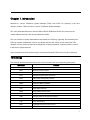
Chapter 1. Introduction
Welcome to “Lenovo ThinkServer System Manager (TSM)” User Guide. For simplicity, in the next
sections, the term “TSM” will refer to “Lenovo ThinkServer System Manager”.
This User Guide describes how to use the TSM on RD550, RD650 and TD350, the overview of the
module features and how to set up and operate the module.
The User Guide is for system administrators responsible for configuring, upgrading, and maintaining the
TSM. As a system administrator once you are familiar with the User Guide, you can access the TSM
remotely from any location to respond to emergencies. If further assistance is required, please, proceed
to the Lenovo support web site.
Some screenshots in this document may be not same as the actual TSM UI, they’re only for reference.
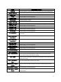
Terminology
The following table lists the terms that are used in this document and its corresponding descriptions.
Abbreviation
AD
Definition
Active Directory
BIOS
Basic Input Output System
BMC
Baseboard Management Controller
CPLD
Complex Programmable Logic Device
DCMI
Data Center Manageability Interface
DHCP
Dynamic Host Configuration Protocol
DIMM
Dual-Inline-Memory-Modules
DNS
Domain Name Service
FRU
Field Replaceable Unit
FQDN
IP
Fully Qualified Domain Name
Internet Protocol
IPMI
Intelligent Platform Management Interface
KVM
Keyboard, Video, and Mouse
LAN
Local Area Network
LDAP
Lightweight Directory Access Protocol
MAC
Media Access Controller
4
ME/NM
Node Manager
NCSI
Network Communication Services Interface
NFS
Network File System
NIC
Network Interface Controller
Nsupdate
Direct Dynamic DNS
NTP
Network Time Protocol
PEF
Platform Event Filter
POST
Power On Self Test
PSU
Power Supply Unit
RAID
Redundant Arrays of independent Disks
RADIUS
SEL
SMASH
Remote Authentication Dial In User Service
System Event Log
Systems Management Architecture for Server Hardware
SMTP
Simple Mail Transfer Protocol
SNMP
Simple Network Management Protocol
SOL
Serial Over LAN
SSH
Secure Shell
SSL
Secure Sockets Layer
TCP/IP
Transfer Control Protocol/Internet Protocol
TDM
ThinkServer Deployment Manager
TSM
ThinkServer System Manager
TSIG
Transaction SIGnature
USB
Universal Serial Bus
VLAN
Virtual Local Area Network
Safety information
WARNING
With reference to either the Guide or other documents, you should always pay particular attention
to safety information before operating the ThinkServer. To ensure full compliance with the existing
certification and licensing, you must follow the installation instructions in the Guide.
Power on / off: the power button does not disable TSM power. To disable the TSM, you must disconnect
the AC power cord from the power outlet. When opening the chassis to install or remove the parts, you
should make sure the AC power cord has been disconnected.
.
5
Chapter 2. Overview of the Lenovo TSM
This topic describes the features of the TSM. The TSM has an embedded operating system that is
integrated in the ThinkServer. Independent of the server operating system, the embedded operating
system can provide a whole set of complete, stable and effective solutions for the server. As a system
administrator, you can manage the server remotely through the network and view system event log
messages.
Features of the TSM
The TSM is accessed through a network connection and if a remote KVM is installed, the user can
remotely connect to an operating system, Embedded with remote access and related control software.
Key features of the TSM are as follows:
•
Embedded Web UI - Remote power on / off, system health, system information, alert notification and
event log.
•
Security - open source SSL
•
Compatible with IPMI V2.0
•
KVM - allow remote viewing and configuring in the POST and the BIOS setup utility
•
Supports Platform deployment management
•
Supports SNMP using both IPv4 and IPv6.
•
Supports the NTP client.
•
Supports USB redirection/ Remote Media (Virtual Media) with the TSM key.
•
Supports routing of management traffic through embedded AnyFabric cards.
•
Supports firmware update, backup, roll back and recovery function.
•
Supports Extended SEL.
•
Supports chassis intrusion detection and alerting.
•
Supports LDAP and LDAPS.
•
Support Email alert for log notification via SMTP.
•
Supports the ME/ NM function.
•
Supports TSM, BIOS and software like TDM, Windows/Linux driver firmware update.
•
Supports SMASH
6
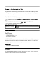
Chapter 3. Configuring of the TSM
This topic describes how to use the server configuration utility to configure the TSM. When first installed,
the TSM by default will search the DHCP server on the network to automatically assign an IP address,
subnet mask and gateway. It is recommended that users manually set a fixed IP address in the BIOS.
To set an IP address, do the following:
1. Press F1 as soon as you see the Lenovo logo screen.
2. From the BIOS setup menu, select TSM Settings ➙ TSM Network Settings ➙Configuration Address
Source.
3. From the Configuration option, you can choose Static or DHCP to set the IP address.
4. When you finish the configuration, save the settings.
Table 1. IPMI 2.0 Configuration submenu
Configuration Address Source
Static
Static IP configuration. IP and the subnet mask can be set manually
DHCP
Dynamic IP configuration. System can obtain IP automatically
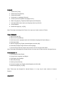
System requirements
Supported Browsers:
•
Firefox version 21+
•
Internet Explorer version 10 or 11
•
Google Chrome version 26+
•
Safari version 5+
To use the Virtual Console, you must also have the Java Run-Time Environment (JRE) properly installed
and working, including the Java plugin for your preferred Web browser. Depending on the JRE version
installed, you may need to lower your Java security to run the Virtual Console.
Supported Java :
•
Java 1.6 to 1.7 Update 55 for KVM/VM
Languages
The TSM supports different languages and locales. Depending on your browser, you may need to follow
some specific steps to use the TSM with your preferred language.
7
Firefox 28
1. Select menu [Tools].
2. Select menu item [Options].
3. Select tab [Content].
4. Click button on Languages [Choose].
5. Click drop-down-box [Select a language to add...].
6. Mark a language e.g. English (United Kingdom) and click [Add].
7. Use button [Move Up] to place your language at the top of the list.
8. Click [OK] twice.
9. Reload web page (e.g. by [F5]).
Note: These steps are designed for Firefox 28. It may vary for other versions of Firefox.
Google Chrome 34
1. Select menu [ALT+E].
2. Select menu item [Settings].
3. Scroll down to the Languages option and click button [Language and input settings...].
4. Click button [Add].
5. Select a language e.g. English (United Kingdom) and click [OK].
6. Click button [Display Google Chrome in this language].
7. Close all Google Chrome windows and re-launch it for this change to take effect.
Note: These steps are designed for Google Chrome 34. It may vary for other versions of Google Chrome.
Internet Explorer 11
1. Go to Windows Control Panel.
2. Choose Clock, Language, and Region.
3. Click Region and Language.
4. Select tab [Formats].
5. Click drop-down [Format].
6. Choose a language e.g. English (United Kingdom) and click [Ok].
7. Reload web page (e.g. by [F5]).
Note: These steps are designed for Internet Explorer 11. It may vary for other versions of Internet
Explorer.
Safari 5.1.17:
8
1. Go to Windows Control Panel.
2. Choose Clock, Language, and Region.
3. Click on Install or uninstall display languages.
4. Choose Install display languages.
5. If you have not downloaded the language pack file you have to launch the Windows Update.
6. Most of the languages packs that you need, will be hidden, so choose 'Restore hidden updates'
and you will see all language packs.
7. Select the language pack you want and click 'Restore' button.
8. After downloading and installing the language pack you might have to restart your computer.
Note: These steps are designed for Safari 5.1.17. It may vary for other versions of Safari.
Supported Locales
The list below presents the locales that are supported by TSM:
•
Chinese Simplified (zh-cn)
•
Chinese Traditional (zh-tw)
•
Chinese Traditional (zh-hk)
•
Danish (da)
•
Dutch (nl)
•
English (en)
•
English (en-us)
•
French (fr)
•
French (fr-fr)
•
German (de)
•
German (de-de)
•
Italian (it)
•
Japanese (ja)
•
Korean (ko)
•
Korean (ko-kr)
•
Portuguese (pt-br)
•
Russian (ru)
•
Spanish (es)
•
Spanish (es-es)
•
Thai (th)
9
Chapter 4. TSM Quick Start
Connecting to the TSM
The TSM has an embedded Web server and an application with multiple standard interfaces. This topic
describes these interfaces and their usages. You can use the TCP/IP protocol to access these interfaces.
For more information about the initial settings, see Chapter 3 “Configuring of the TSM” on page 7. The
default user name and password are as follows:
•
Username = lenovo
•
Password = len0vO
The TSM is accessible through standard Java-enabled Web browsers with HTTP and HTTPS. When
accessing the TSM via the HTTPS protocol, the browser may prompt you to trust and install the security
digital certification. Just follow the prompts to import and confirm the certification.
Logging on
To log on to the TSM, please do following:
1. Enter the IP address assigned by the TSM into the Web browser.
For example:
http://10.99.87.131/
For secure connection, refer to the following example:
https://10.99.87.131/
The web browser will then be directed to the logon page of the TSM.
2. On the logon page of the TSM, enter the user name and password.
For example:
• Username = lenovo
• Password = len0vO
3. Click Sign in to view the home page of the TSM.
10
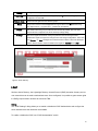
Navigation
When you have successfully logged on to the TSM, the TSM dashboard is displayed. You can select the
left or right arrows to navigate between dashboard pages. The information and tasks found on each
dashboard page is listed in the following table.
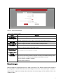
Table 2 . Properties on the TSM dashboard:
11
Tab
Dashboard1
Comments
This dashboard contains the following information:
Dashboard2
•
Current Time
•
SYSTEM SUMMARY
•
LATEST EVENT LOG ENTRIES
•
Ambient and PSU status
•
POWER CONTROL
•
LAUNCH CONSOLE
•
NIC
This dashboard contains the following features:
•
FRU Inventory
•
Power Management
•
Users
•
Networking
•
Virtual Console
•
Logging
•
SMTP Settings
•
NTP Settings
•
SSL Cert. Settings
•
Services Management
•
Sensor Monitoring
•
Firewall
•
Factory Reset
•
PEF Management
•
Firmware Update
•
Backup and Restore
•
Serial Over LAN
Table 3. Properties on the top of the TSM dashboard:
Tab
Comments
Hostname
Show current server MAC address
Username
Show current user name
Search icon
Search the features by key word
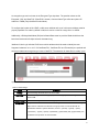
Logging out
You can log out of the dashboard at any time by clicking on the gear icon located in the bottom right
corner of the page and selecting “Logout.” The TSM will only terminate sessions that are properly logged
out from or if they have exceeded the inactive timeout period. The inactive timeout period can be
configured through the Services Management page. The default timeout period for a Web session is 30
12
minutes. Also, in the same Services Management page, it is possible to terminate any session, including
these inactive sessions not properly ended by a log out.
13
Chapter 5. TSM Web Console Options
This topic describes the TSM web console. You can check the status of sensors presented by the
ThinkServer, view the installed hardware components, grant access to other users, and configure TSM
settings. This section presents all available features and the possible operations for each one.
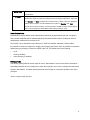
Log in and access control
In order to access all features available on the TSM, you must first log in. The TSM supports local users
as well as Active Directory and LDAP. You may need to ask your system administrator about credentials
to log in.
Note:
To log in to the TSM web interface, you must provide both a valid Username and a Password. Both fields
are mandatory and should be filled properly. For Active Directory and LDAP services, the Username field
doesn't require the domain before the username itself (for example, domainABC\userXYZ).
By default, the TSM will try to authenticate the provided credentials in the following order:
1. Locally
2. LDAP (if enabled)
3. Active Directory (if enabled)
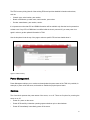
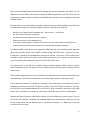
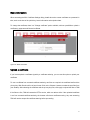
Figure 1. Logon page
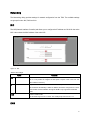
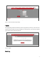
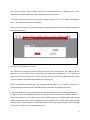
Forgot password
The “Forgot password” mechanism is only available for local users that have a valid email address
14
registered in TSM. LDAP and Active Directory users must contact the system administrator to reset their
password. Also, because the “Forgot password” mechanism relies on email messages SMTP must be
properly configured in TSM.
If you forget your password, the TSM can create a new password and send it to your registered email.
Just click the "Forgot Password?" link and input your username. You will receive an email message
containing the new password to access the TSM. After logging in using your new password, you can
change the password by accessing your profile.
Another method can be used to reset a forgotten password:
Go into the BIOS setup menu and select “TSM Settings” -> ”TSM User Account settings” -> “Change Pa
ssword” . Select the option “Create New Password”. This password is for User ID 2 and Administrative P
assword.
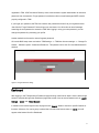
Figure 2. Forgot Password dialog
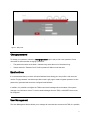
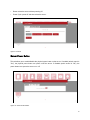
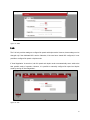
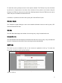
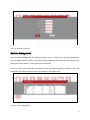
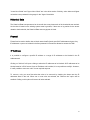
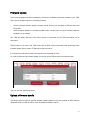
Dashboard
After logging in, the TSM presents a Dashboard page showing overall server status. Use the left and right
arrows to navigate through other Dashboard pages that contain icons to access features such as “SMTP
Settings”, “Users” and “Virtual Console”.
In addition to the left and right arrows, all pages have a “Search” button to search for specific features or
functions. Moreover, if a new log entry is added due to an abnormal sensor state, an “Alerts” icon will
appear at the bottom left of the Dashboard.
15
Figure 3-1. Dashboard 1
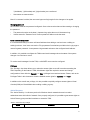
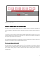
Figure 3-2. Dashboard 2
Edit profile
The "Edit Profile" option of the TSM allows you to change your own password and email address. "Edit
Profile" is available only for local users. Active Directory and LDAP users should contact the system
administrator and request to change the password.
To edit your profile select the Settings icon at the bottom right of the Dashboard.
16
Figure 4. Edit profile
Change password
To change your password, select the "Change password" option and provide a new password. Some
rules must be observed when changing a password:
•
The password must be at the least 1 character long and at the most 16 characters long.
•
Values entered in "Password" and "Confirm password" fields must be the same.
Email address
It is recommended that you enter a valid email address when editing your user profile. Local users can
use the "Forgot password" mechanism provided on the Login page to reset a forgotten password. A new
password is generated and sent to the configured email address.
In addition, it is possible to configure the TSM to send email messages when the status of the system
changes or a critical error occurs. To receive email messages from the TSM, a valid SMTP server must
be configured.
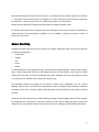
User Management
The User Management feature allows you to manage all users that have access to the TSM. It is possible,
17
for example, to create local users configure Active Directory and LDAP servers and grant access rights to
Active Directory or LDAP groups to use the features available on the TSM.
Local Users
Figure 5. Local Users
Local users are user accounts that are valid only to access TSM and are not related to any other directory
services such as Active Directory and LDAP. The Local Users tab presents a table with all existing users.
In order to create a new local user account, click the "Add User" option. Another dialog will open with
fields to configure a new local user account. It is possible to have up to 9 local users configured.
To remove local user accounts, you must first select the local users to be removed by checking the boxes
next to the usernames. When one or more local users are selected, the "Delete Users" option will be
enabled. Clicking on this option will remove the selected local user accounts. Note that it is not possible to
remove the user currently logged in.
To edit local user account, click on the username. A dialog will open that allows you to change password,
email address, and other fields. However, it is not possible to change the username itself.
Username
When adding a new user, a username must be provided. A valid username must follow a few rules:
•
Username must be at the least 1 character long and at the most 16 characters long.
•
Alpha-numeric characters are allowed in the username, but it must start with an alphabetical
character.
•
Special characters, such as ','(comma), '.'(period), ':'(colon), ';'(semicolon), ' '(space), '/'(slash),
18
'\'(backslash), '('(left bracket) and ')'(right bracket), are not allowed.
•
Usernames are case-sensitive.
Note: If a username is edited, the user must logout and login again for the changes to be applied.
Changing password
All local users must have a password configured. Some rules must be observed when setting or changing
the password:
•
The password must be at the least 1 character long and at the most 16 characters long.
•
Values entered in "Password" and "Confirm password" fields must be the same.
Email address configuration
It is recommended that you enter a valid email address when adding a new local user or editing an
existing local user. Local users can use the "Forgot password" mechanism provided on the Login page to
reset a forgotten password. A new password is generated and sent to the configured email address.
In addition, it is possible to configure the TSM to send email messages when the status of the system
changes or a critical error occurs.
To receive email messages from the TSM, a valid SMTP server must be configured.
Privileges
The “Privilege” drop-down allows you to select the access rights a user will have when accessing the
TSM. Depending on the feature in TSM, Administrator rights are required to access and change
configurations. Users with the “Operator” or “User” privileges have restricted access. Please, refer to the
Privileges Table in this document to view the detailed access rights for “Operator” and “User”.
In addition to the overall user privilege, it is also possible to explicitly configure access rights to Virtual
Console (KVM) and Virtual Media when adding or editing a group.
Active Directory
The “Active Directory” is a directory service for Windows domain networks that can be used to
authenticate users in this kind of network. Once properly configured, it is possible to grant access rights to
Active Directory groups and their members to access the TSM.
Table 4. Active Directory settings:
Option
Comments
19
Settings
Add Group
Configure and manage the domain controller of the Active Directory to access TSM.
Grant access rights to an Active Directory group. Up to 5 Active Directory groups can be
configured to access TSM.
Remove Group
Group
Remove access rights from the selected groups.
Group name must be at the least 1 character long and at the most 64 characters long.
Only alpha-numeric, '-' (hyphen) and '_' (underscore) are allowed.
Domain
The domain where the group is located must be entered. By default, this is the same
domain that was configured in the Active Directory settings dialog.
Privilege
The access rights the members of the group will have when accessing the TSM.
Administrator rights are required to change access and change configurations. Users with
the “Operator” or “User” privileges have restricted access. Please, refer to the Privileges
Table in this document to check the detailed view rights for “Operator” and “User”.
Figure 6. Active Directory
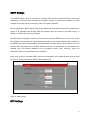
LDAP
Similar to Active Directory, the Lightweight Directory Access Protocol (LDAP) is another directory service
over network that can be used to authenticate users. Once configured, it is possible to grant access rights
to LDAP groups and their members to access the TSM.
Setting
The "LDAP Settings" dialog allows you to enable or disable the LDAP Authentication and configure the
server address where the directories are available.
To enable or disable the LDAP, use "LDAP Authentication" switch.
20
An encryption type can be chosen in the Encrypted Type dropdown. The possible values are 'No
Encrypted', 'SSL' and 'StartTLS'. If StartTLS is chosen, Common Name Type offers two options: IP
Address or FQDN (Fully Qualified Domain Name).
To configure the location of the LDAP, a valid server address and a port in this server address must be
properly specified. Port value by default is 389, but it can be a value in a range from 1 to 65535.
Additionally, a Distinguished Name (DN) and a Search Base must be provided. Both should be at the
least 4 and at the most 63 alpha-numeric characters long.
'Attribute of User Login' tells the LDAP server which attribute should be used to identify the user.
Supported values are 'cn' or 'uid'. 'CA Certificate File', 'Certificate File' and 'Private Key' are optional and
can be provided when encryption type is set to 'StartTLS'. The extension for these files is usually '.pem'.
Figure 7. LDAP
Table 5. LDAP settings:
Option
Settings
Add Group
Comments
Set and manage the LDAP server to access TSM.
Grant access rights to an LDAP group.Up to 5 LDAP groups can be configured to
access TSM.
Remove Group
Group name
Remove access rights from the selected groups.
Group name must be at the least 1 character long and at the most 16 characters long.
Alpha-numeric characters are allowed in the group name, but it must start with an
alphabetical character. Special characters, such as ','(comma), '.'(period), ':'(colon),
';'(semicolon), ' '(space), '/'(slash), '\'(backslash), '('(left bracket) and ')'(right bracket), are
not allowed. Group names are case-sensitive
21
Search Base
Retrieve information about all objects within a specific scope that have certain
characteristics
Privilege
The access rights the members of the group will have when accessing the TSM.
Administrator rights are required to change access and change configurations. Users with
the “Operator” or “User” privileges have restricted access. Please, refer to the Privileges
Table in this document to view the detailed access rights for “Operator” and “User”.
Besides the overall user privilege, it is also possible to explicitly configure access rights to
Virtual Console (KVM) and Virtual Media when adding or editing a group.
Authentication Order
Authentication Order presents which authentication method will be applied when the user is logging in.
The provided credentials will be checked against the first authentication method. If failed, the second
authentication method will be tried and so on.
This tab will only be displayed if Active Directory or LDAP are enabled. Otherwise it will be hidden.
It's possible to reorder the methods by dragging and dropping their boxes. Also, it's possible to restore the
default sorting by clicking on 'Restore to default order' link. The default order is the following:
•
Local
•
LDAP (if enabled)
•
Active Directory (if enabled)
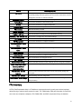
Privileges Table
TSM allows granting different access rights for users. “Administrator” users have access to all features
and settings available and can modify them. Users with “Operator” and “User” privileges will have limited
access to the features. The tables below present the access rights for users with “Operator” and “User”
privileges.
Table 6. Privileges Table (Operator):
22
Feature
Dashboard
Backup and Restore
Factory Reset
Firewall
Firmware Update
FRU Inventory
Access Rights (Operator)
Read all information provided, but can't use the On/Off switch of Power Management.
Can't access the feature, backup or restore configurations.
Can't access the feature or start a factory reset.
Read all settings, but can't change them.
Can't access the feature or update firmware.
Read all information provided.
Logging - Event Log
Read all information provided, but can't clear the event log entries.
Logging - Audit Log
Read all information provided, but can't enable/disable audit log.
Networking - NIC
Read all settings, but can't change them.
Networking - DNS
Read all settings, but can't change them.
Networking - Link
Read all settings, but can't change them.
NTP Settings
Read all settings, but can't change them.
PEF Management
View the list of event filters, alert policies and LAN Destinations, but can't add, edit or
remove them.
Power Management -
Check the Power Status, but can't use any of the power controls
Power Status
Power Management -
Can't access or change the power button settings.
Power Button
Sensor Monitoring
Serial Over LAN
Services Management
SMTP Settings
SSL Certificate Settings
Users - Local Users
Users - Active Directory
View current readings of the sensors, but can't open the details for the sensors.
Read all settings, but can't change them.
View current settings for all services, but can't change them or view active sessions.
Read all settings, but can't change them.
Access information about the current certificate, but can't change the certificate.
View list of users, but can't add, edit or remove users.
View list of groups and if Active Directory is active, but can't add, edit or remove
groups and can't change Active Directory settings.
Users - LDAP
View list of groups and if LDAP is active, but can't add, edit or remove groups and can't
change LDAP settings.
Users - Authentication
View current authentication order but can’t change.
Order
Virtual Console - Console
Launcher
View the console screenshot and launch console if the specific privilege has been
given.
Virtual Console - Settings
Read all settings, but can't change them.
Virtual Console - Remote
View if remote images are enabled or not and the list of remote images, but can't
Images
change anything.
Table 7. Privileges Table (User):
23
Feature
Dashboard
Access Rights (User)
View System Summary, the latest Event Logs, Sensors and Launch Console (if
the specific privilege has been granted), but can't use the On/Off switch of Power
Management, view time or network information.
Backup and Restore
Factory Reset
Firewall
Firmware Update
FRU Inventory
Can't access the feature, backup or restore configurations.
Can't access the feature or start a factory reset.
Can't access the feature or configure firewall rules.
Can't access the feature or update firmware.
Read all information provided.
Logging - Event Log
Read all information provided, but can't clear the event log entries.
Logging - Audit Log
Read all information provided, but can't enable/disable audit log.
Networking - NIC, DNS and Link
Can't access or configure any of the network settings.
NTP Settings
Can't access the feature or change NTP settings.
PEF Management
Can't access the feature or configure event filters.
Power Management - Power
Check the Power Status, but can't use any of the power controls
Status
Power Management - Power
Can't access or change the power button settings.
Button
Sensor Monitoring
Serial Over LAN
Services Management
SMTP Settings
SSL Certificate Settings
Users - Local Users, Active
View current readings of the sensors, but can't open the details for the sensors.
Can't access the feature or configure Serial Over LAN.
View current list but can't configure services.
Can't access the feature or configure SMTP Settings.
Access information about the current certificate, but can't change the certificate.
Can't access or configure any of the user settings.
Directory, LDAP and
Authentication Order
Virtual Console - Console
Launcher
Virtual Console - Settings
Virtual Console - Remote Images
View the console screenshot and launch console if the specific privilege has
been given.
Read all settings, but can't change them.
View if remote images are enabled or not and the list of remote images, but can't
change anything.
FRU Inventory
A FRU (Field Replaceable Unit) is a ThinkServer component that can be easily removed and replaced
without having to send the entire system for repair. The TSM displays FRU part information for AnyFabric
card, riser card, midplane, backplane, CPU, DIMM, PSU, and RAID components if they are installed.
24
The FRU Inventory dialog lists all of the existing FRUs and provides detailed information about them,
such as:
•
Chassis: type, serial number, part number.
•
Board: manufacturer, product name, serial number, part number.
•
Product: manufacturer, part number, version.
It is important to notice that CPU and DIMM information will be available only after the host is powered on
at least once. If any CPU or DIMM item is modified while the host is powered off, you must power it on
again in order to get the updated information in TSM.
Use the dropdown list at the top of the page to select a specific FRU and see details about it.
Figure 8. FRU Inventory
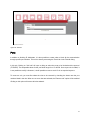
Power Management
Power Management allows you to monitor and manipulate the power status of the TSM. It is possible, for
example, to power on/off the server, and enable or disable the physical power button.
Controls
The Controls tab presents the power status of the server; on or off. There are 5 options for powering the
server on or off:
•
Power On: power on the server.
•
Power Off Gracefully: initiate the operating system shutdown prior to the shutdown.
•
Power Off Immediately: immediately power off the server.
25
•
Reset: reboot the server without powering off.
•
Power Cycle: power off and then reboot the server.
Figure 9. Controls
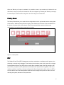
Server Power Button
This tab allows you to enable/disable the physical power button on the server. If enabled (switch control is
"On"), the physical power button can power on/off the server. If disabled (switch control is "Off"), the
power button can’t power the server on or off.
Figure 10. Server Power Button
26
Networking
The Networking dialog provides settings for network configuration from the TSM. The available settings
are grouped in tabs: NIC, DNS and Link.
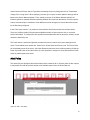
NIC
The NIC (Network Interface Controller) tab allows you to configure the IP address and VLAN for the active
NIC. It also shows the MAC address of the active NIC.
Figure 11. NIC
Table 8. NIC settings:
Option
NIC
(Dedicated / Shared)
Comment
With 'Active NIC' control, it is possible to select which NIC to use. With the shared
NIC, it is not possible to configure the link speed or duplex mode in the 'Link' tab.
MAC Address is read only.
IP
IPv4 / IPv6
Only IPv6 can be disabled. For both IPv4 and IPv6 it is possible to enable DHCP to
get an address automatically. If DHCP is disabled, all fields to configure IPv4 or IPv6
must be filled and OS installation through the iKVM is only supported in dedicated
mode.
VLAN
Select to enable VLAN.
The VLAN ID range is from 2 to 4094. The VLAN priority value is from 1 to 7.
DNS
27
There are several DNS (Domain Name Service) settings that can be configured in the "DNS" tab. The
"DNS Service" switch allows you to enable or disable all DNS configurations in the TSM. There is also a
specific switch control to enable or disable multicast DNS, which provides a zero configuration host name
resolution service.
The host name can be automatically or manually configured using the controls available in the "DNS" tab.
If the host name needs to be manually configured, there are a few rules to be observed:
•
Must have only alpha-numeric characters and '-' (hyphen) and '_' (underscore).
•
No other special characters are allowed.
•
The first and the last character can’t be '-' (hyphen).
•
Host name must be 1 to 63 characters long.
•
This function may change the IP address of the device, and you may lose the connectivity in this
browser session. Reconnect using a new browser session after applying the changes
The ‘Register BMC’ option allows you to register the TSM using one of the following options: Nsupdate
(Direct Dynamic DNS), DHCP Client “FQDN” to register through the DHCP server, “Hostname” or None.
If ‘Nsupdate’ is selected, TSIG authentication may also be required. In this case, a TSIG private file will
be needed. Use the 'Choose File' button to select a TSIG private file on your computer. The date and time
of the configuration will be displayed in the 'Current TSIG Private File' field.
The domain name for the NIC can be viewed using the 'Domain Settings' control under the 'Domain
Name Configuration' group. The same control has a 'Manual' option, allows the user to manually enter the
domain name.
The last DNS configurations are to set up the DNS server addresses (the ones used to retrieve URLs and
other addresses). The DNS server addresses can be automatically retrieved or manually entered.
If the 'DNS Server Settings' is configured to 'Automatic', the IP addresses for the DNS servers will be
automatically retrieved using DHCP. Therefore, this option is only valid if DHCP is enabled. In this case,
the 'IP Priority' must be selected between 'IPv4' and 'IPv6'. If 'IPv4' is selected, it will retrieve 2 IPv4 DNS
servers and 1 IPv6 DNS server. Otherwise, it will retrieve 2 IPv6 DNS servers and 1 IPv4 DNS server.
Selecting the 'Manual' option for 'DNS Server Settings', at least one DNS server must be typed - it can be
an IPv4 or an IPv6 address. If desirable, two additional DNS servers can be entered in either IPv4 or IPv6
format. In other words, with the 'Manual' option, it is possible to configure 1 to 3 DNS servers using any
mix of IPv4 or IPv6 formats.
28
Figure 12. DNS
Link
The 'Link' tab provides settings to configure link speed and duplex mode. However, these settings can be
changed only if the dedicated NIC is active. Otherwise, if the user has a shared NIC configured, it is not
possible to configure link speed or duplex mode.
If 'Auto Negotiation' is turned on, both link speed and duplex mode are automatically set to achieve the
best possible mode of operation. However, it is possible to manually configure link speed and duplex
mode by turning off 'Auto Negotiation'.
Figure 13. Link
29
Virtual Console
Use the Virtual Console to access the server through the network. The Virtual Console dialog provides
both "Launch Console" feature and the whole set of configurations for the console.
Console Launcher
The "Console Launcher" tab has a button to launch the Virtual Console. In addition to the "Launch
Console" button, the tab also presents a screenshot of the server.
In order to launch the Virtual Console, you must have the Java Run-Time Environment (JRE) properly
installed and working, including the Java Plugin for your preferred Web browser. Depending on the JRE
version installed, you may need to lower your Java security to run the Virtual Console. The recommended
JRE version to use with the Virtual Console is JRE1.7.0_51-b13.
Figure 14. Console Launcher
Settings
The ‘Settings’ tab presents all available settings for the Virtual Console.
30
Figure 15. Virtual Console Settings
Table 9. Virtual Console settings:
Option
Comment
KVM Encryption
Enable/Disable encryption on the KVM data for the next redirection session.
Media Encryption
Enable/Disable encryption on Media data for the next redirection session. Note enabling
this will automatically close any existing remote KVM or Virtual Media sessions.
Retry Count
Retry Time Interval
Local Monitor
Used to configure the number of times to be retried in case a KVM failure occurs.
Used to configure the number of seconds to wait for subsequent retries.
The “Local Monitor” option is used to control whether or not it will be possible to turn on
and turn off the host monitor in the Virtual Console.
Automatically turn local
monitor off when
Used to automatically turn the host monitor off when the Virtual Console is launched. It is
also available only if 'Local Monitor' is enabled.
launching the Virtual
Console
Mouse Mode
The mouse mode setting should be configured according to the installed operating system.
Choose “absolute” for Windows operating systems and RHEL 6 and later.
Choose “relative” for RHEL 4 or RHEL 5.
Choose “other” for SLES 11.
Remote Images
Remote images are image files that can be used by the server. The “Remove Images” tab provides all
the configurations needed. TSM assumes that all images will be on the same remote path. To enable or
disable remote images and configure the path where the remote images will be available, click on the
“Settings” button.
31
When remote media support is turned “on”, it is possible to select a remote image file by clicking on an
image type and the user can start or stop remote media direction the remote media redirection by using
the action buttons. However, only one remote image can be configured for each image type: Floppy,
CD/DVD and HD.
To start or stop the remote images redirection, there are action buttons available for each one of them. If
the image redirection failed for some reason, its status will be updated properly.
Among the action buttons, there is also a specific button to clear the image redirection. By clicking on this
button, the image file name is de-associated from the image type.
Figure 16. Virtual Console Remote Images
The "Remote Images Settings" dialog allows enabling or disabling remote images redirection and
configuring the network location where the image files are available.
To enable or disable the remote images redirection, use the "Remote Media Support" switch.
To configure the location of the remote image files, a valid server address and a source path in this server
address must be properly specified. Additionally, it is required to select between "NFS" and "Samba
(CIFS)" in the Share Type drop down. If "Samba (CIFS)" is selected, the domain name and valid
username and password must also be provided in order to grant access to the files located in the
specified path. Any change in the remote media settings will close all virtual media redirection sessions
and restart them.
32
Figure 17. Virtual Console Remote Image Settings
Logging
The Logging dialog presents two different logs: Event Log and Audit Log. Event Log, as the name says,
presents the events related to the sensors available in the TSM. Audit Log, on the other hand, displays
events related to actions performed by the users.
Figure 18. Logging
Event Log
33
To assist the event log analysis, there are a few options available. The "Filter By" drop down list allows
log entries for a single sensor to be shown. Also, the date of the log entries can be shown using the
timezone from TSM or the time zone from the client. Switching between client and TSM time zone may be
useful if they are not located in the same time zone.
If desirable, it is possible to clear the event log using the "Clear All Entries" option.
SEL Record Details
The ThinkServer System Manager is able to show detailed information about an event log entry: SEL
Data and Extended SEL Data.
SEL Data
The 'SEL Data' table displays the raw data of an event log entry, using a hexadecimal format.
Extended SEL Data
The 'Extended SEL Data' table displays the extended raw data of an event log entry, using a hexadecimal
format. It is important to notice that not every event log entry has extended data.
Audit Log
The Audit Log can be disabled so that no new events are registered to this log. To access this
functionality, change the Audit Log State switches.
Figure 19. Audit Log
34
SMTP Settings
In the SMTP Settings dialog, it is possible to configure SMTP servers so that the TSM can send email
notifications to the users when the status of the system changes or a critical error happens. An email
message can be also sent to a local user in case of a forgotten password.
When configuring the SMTP settings, both sender address (the email address that will be included as the
sender of all messages sent through TSM) and machine name (the name of the SMTP server). In
addition, an SMTP server must be configured.
The TSM allows configuration of both the primary and the secondary SMTP server. For each one, a valid
IPv4 address must be entered as "Server Address" as well as a port number (default is 25). In addition, if
the SMTP server requires authentication, the "Authentication required" switch must be moved to "On" and
both username and password must be filled. Username must be a 4-64 characters and must start with an
alphabet. Also, the following characters are not permitted: comma, colon, semicolon, space and
backslash. Password must be between 4-64 characters.
At any time, primary or secondary SMTP servers can be disabled, which means that they won't be used
by TSM. To do that, just move the SMTP Support switch to off.
Figure 20. SMTP Settings
NTP Settings
35
In the NTP Settings dialog, you can set the date and time of TSM. Basically, there are two options
available: Automatically synchronize with NTP Server or Manually set date and time. Besides, in the NTP
Settings dialog, you must provide the time zone where the TSM is located.
Figure 21. NTP Settings
Automatically synchronize with NTP Server
When selecting this option, date and time will be automatically synchronized with an NTP server. It is
possible to configure two NTP servers, primary and secondary. In case the primary NTP server is not
reachable, the secondary NTP server will be contacted to synchronize date and time.
Manually set date and time
In this option, both date and time must be manually entered. There are specific formats to be followed
when entering values for date and time. For date, the following format should be used: mm/dd/yyyy. And,
for time, the TSM expects 24-hour format.
SSL Certificate Settings
If you want to secure access to TSM, you can configure an SSL certificate. In the SSL Certificate Settings
dialog, it is possible to view details about the current SSL certificate, upload a new certificate or generate
a self-signed certificate.
36
Basic Information
When accessing the SSL Certificate Settings dialog, details about the current certificate are presented in
tabs, such as the size of the public key, issuer information and expiration date.
To change the certificate, there is a "Change certificate" option available, with two possibilities: upload a
certificate or generate a self-signed certificate.
Figure 22. Basic Information
Upload a certificate
If you have acquired a certificate signed by a certificate authority, you can use this option to upload your
certificate.
To use a certificate from a trusted certificate authority, two files are required: the certificate itself and the
privacy key. Both files should be of pem format. Click on the “Browse” buttons to select the pem files from
your desktop. After selecting the certificate and the privacy key files, click apply to upload the files to TSM.
If the files are fine, TSM will restart the HTTPs service, which can take a while. If the uploaded certificate
is not from a trusted certificate authority, the browser will show a certificate warning. Any user accessing
TSM will need to accept this certificate warning before proceeding.
37
Figure 23. Upload a certificate
Generate a certificate
If you want to secure access to TSM but don't have a certificate signed by a trusted certificate authority,
you still can use a certificate by selecting the "Generate a certificate" option in the "Change certificate"
menu.
To generate a self-signed certificate, all fields presented in the corresponding dialog must be properly
filled. Specifically about the certificate validity, a self-signed certificate can be valid from 1 to 3650 days.
When generating a new SSL certificate, TSM will restart the HTTPs service, which can take a while.
Additionally, when the HTTPs service is back again, the browser will show a certificate warning, as this is
not a certificate from a trusted certificate authority, although it is not a security risk. Any user accessing
TSM will need to accept this certificate warning before proceeding.
38
Figure 24. Generate a certificate
Services Management
Use the Services Management to handle the services running on TSM. In the Services Management,
there are details about the status of the services (active/inactive), the secured and non-secured ports
being used and the number of active sessions by each service.
Click on a service name to activate or de-activate it and to change its settings. In addition, to see more
details about the opened sessions, click on the numbers in the Sessions cell.
Figure 25. Services Management
39
The services settings dialog provides controls to activate/de-activate the selected service. Also,
depending on the selected service, a few configurations can be performed.
To activate or de-activate the service, change the "State" switch to "On" or "Off". When de-activating a
service, all opened sessions will be terminated.
There are two tabs in the services settings dialog, providing information and some possible configurations:
Network and Sessions.
Figure 26. Service Management – Network
The Network tab presents the non-secured and secured ports configured for the selected service.
However, not every service allows changing the port numbers. More specifically, it is not possible to
change the ports for media services (CD/DVD, and HD), as well as for KVM. In addition, telnet provides
only a non-secure port whereas SSH provides only a secure port.
Both for non-secure and secure ports, the acceptable values range from 1 to 65535. If required, it is
always possible to restore the port to the default value by using the "Use default port" option.
In the Sessions tab, the number of active sessions and the maximum number of sessions is displayed.
As “Figure 25. Services Management” shows, the maximum number of sessions for CD/DVD media is 1,
for HD media service is 3, for KVM service is 4 and for Web service is 20. Clicking on them will open the
session management, which allows managing the active sessions. Also, for KVM, SSH, telnet and Web
services, there is an extra option to configure the session time-out by directly entering a value in the text
input or by moving the cursors from the slider control.
40
Web and the KVM timeout values can be set from 5 - 30 minutes. SSH and Telnet values can be set from
1 – 30 minutes. These values should be in multiples of 1 minute. Session time-out for SSH and Telnet are
the same. So if a timeout is set in SSH, the TSM will do the same for Telnet service.
Please note that after reset TSM may need 8 minutes to use SSH connection TSM.
It is worth to mention that, when changing a service configuration, as the service needs to be restarted, all
opened sessions will be terminated. In addition, it is not possible to modify the maximum number of
sessions for any service.
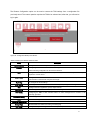
Sensor Monitoring
Detailed information about the sensors is shown in the Sensor Monitoring dialog. Sensors are organized
in the following categories:
•
Temperature
•
Voltage
•
Fan
•
Power
•
Others
To analyze sensors from a specified category, just access the corresponding tab. Inside of each category
(tab), a table presents the sensors for that category and the current readings. If the value for current
reading is fine, the color of the current reading will be green. Otherwise, the color may change to orange
or red. Sensors not available at the moment will appear in gray.
For temperature sensors, the values can be shown in Celsius (°C) or Fahrenheit (°F). The “Current
Reading” field for CPU1 and CPU2 DTS represents the number of degrees Celsius below the maximum
temperature of the CPU. Having a negative value displayed in those fields shows the system is working
correctly.
Clicking on a sensor name will open another dialog presenting a real-time gauge with the current reading,
the thresholds and a bar chart for log entries. However, as the current reading and the bar chart don't
make sense for non-scalable sensors, these sensors won't open a dialog to present detailed information.
41
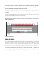
Figure 27. Sensors Monitoring - Temperature
The TSM is able to show detailed information about the sensors: current reading, thresholds and a bar
chart to represent the quantity of events already stored in the system event logs.
Thresholds
All scalable sensors in TSM have a few thresholds to determine their status:
•
Lower Non-Recoverable
•
Lower Critical
•
Lower Non-Critical
•
Upper Non-Critical
•
Upper Critical
•
Upper Non-Recoverable
When the reading for a sensor reaches one of these thresholds, a new system event log entry is included
and some action may be required from the system administrator. For example, if a CPU temperature
sensor overpasses the "Upper Non-Recoverable" threshold, the system administrator could try to
decrease the ambient temperature and check if the readings for this sensor decrease too.
Current Reading
The current reading gauge represents the sections delimited by these thresholds too. Readings lower
than "Lower Non-Recoverable" are represented as a darker red section. Readings between "Lower NonCritical" and "Lower Non-Recoverable" are located in the lighter red section. And any reading between
42
"Lower Non-Critical" and "Upper Non-Critical" are in the white section. Similarly, other darker and lighter
red sections are presented in the gauge for the "Upper" thresholds.
Historical Data
The Historical Data area presents a bar chart with how many times each of the thresholds was reached.
As the chart is based on the existing system event log entries, if there are no log entries for the sensor
related to the thresholds, the Historical Data area may appear in blank.
Firewall
Firewall can be used to define rules to block network traffic from/to specific IP addresses and ports. Any
IP addresses or ports not included in the lists presented in Firewall are allowed to access the TSM.
IP Address
It is possible to configure a specific IP address or a range of IP addresses to be blocked in the IP
Addresses tab.
Clicking on "Add rule" will open a dialog to select the IP addresses to be blocked. All IP addresses to be
blocked must be in IPv4 format. Once an IP address rule is added, it is not possible to modify it. However,
it is still possible to remove a rule if it is not required anymore.
To remove a rule, you must first select the rules to be removed by checking the boxes near the IP
addresses listed in the rule. When one or more rules are selected, the "Remove rule" option will be
enabled. Clicking on this option will remove all rules selected.
43
Figure 28. Firewall
Ports
In addition to blocking IP Addresses, it is also possible to create rules to block all the communication
through specific port numbers. This can be done by accessing the "Ports" tab in the Firewall dialog.
In this tab, Clicking on "Add rule" will open a dialog to select the ports to be blocked and the protocol
(TCP/UDP). The acceptable values for the port fields range from 1 to 65535. Once a port rule is added, it
is not possible to modify it. However, it is still possible to remove a rule if it is not required anymore.
To remove a rule, you must first select the rules to be removed by checking the boxes near the port
numbers listed in the rule. When one or more rules are selected, the "Remove rule" option will be enabled.
Clicking on this option will remove all rules selected.
44
Figure 29. Port
Add an IP address rule
There are two options while creating an IP address rule: block an IP address or block a range of IP
addresses. In both cases, the expected values for IP addresses are in IPv4 format.
When the "Block an IP address" is selected, it is possible to enter a valid IPv4 address to be blocked. In
other words, communications from/to the specified IPv4 address will not be allowed.
Instead of blocking only one IP address at a time, the Firewall allows user to specify a range of IPv4
addresses to be blocked by selecting the "Block a range of IP addresses". For that, the fields "IP address
from:" and "IP address to:" must be filled with valid IPv4 addresses.
When a new IP address rule is saved, all related IP addresses are immediately blocked so that opened
sessions in TSM from the blocked IP addresses will be closed.
Add port rule
The rules to block ports are very similar to the IP address rules. When adding a new port rule, it is
possible to determine a unique port to be blocked or a range of ports. Either way, the acceptable values
for the port fields range from 1 to 65535 and the protocol, TCP or UDP, must be selected when
configuring a new rule.
45
When the "Block a port" option is selected, it is possible to enter a port number to be blocked. On the
other hand, a range of ports to be blocked can also be configured by selecting the "Block a port range".
For the last option, the fields "Port range from" and "Port range to" must be filled.
Factory Reset
The Factory Reset allows you to restore all the configurations to their original state and the existing data
will be erased. While the Factory Reset is ongoing, other features and services will be unavailable and
the device will reboot within a few minutes. Once you proceed with the operation all the current
configuration is lost and the factory reset can’t be undone.
Figure 30. Factory Reset
PEF
The Platform Event Filter (PEF) Management provides a mechanism to configure specific actions to be
performed on certain event messages. These actions include reboot, power cycle, power off, and trigger
an alert (Platform Events Trap [PET] and/or e-mail). When a platform event occurs (for example, a fan
probe failure), a system event is generated and recorded in the System Event Log (SEL). If this event
matches a platform event filter previously configured, this filter will generate an alert, and then a PET or
an e-mail alert is sent. If the same platform event filter is also configured to perform an action, such as
rebooting the system, that action is also performed.
46
Therefore, in order to properly configure a platform event filter, you must follow the steps below:
1. Add a LAN Destination.
2. Add an Alert Policy using the previously created LAN Destination and associate with a specific
policy number.
3. Add an Event Filter using the same policy number previously used in the step above.
Event Filter
The Event Filter tab displays a table with event filters currently in use. It is possible to add new event
filters, delete the existing event filters by marking them. In order to edit an existing event filter, click on its
ID.
Figure 31. PEF - Event Filter
Add and edit an event filter
TSM allows adding an event filter to trigger a message to a specific destination when a specific sensor
event happens. The message and destination are configured on 'Alert Policy' tab and can be chosen on
'Filter Action' section.
When adding or editing an event filter, it is possible to specify which sensor event will trigger an action or
an alert. In order to do that, the 'Sensor Configuration' section presents some controls: Sensor Type,
47
Sensor Name and Events. Sensor Type filters the existing sensors by categories such as Temperature,
Voltage, Fan, among others. When specifying a sensor type, only the sensors related to that type will be
listed on the Sensor Name dropdown. Then, selecting a sensor in the Sensor Name dropdown, the
Events dropdown is updated and allows selecting between all events from that sensor or sensor specific
events. If the latest option is selected, some additional controls will appear to choose the sensor events
for the filter being configured.
In the 'Filter Action' section, it is possible to select both the Alert Policy Number and a Power Action.
There are 15 different Alert Policy Numbers available and each of them may have one or more alert
policies associated. To configure the alert policies and associate them with an alert policy number, please
access the Alert Policy tab.
The Power Action is performed right after the alerts and can be useful to avoid some damages to the
server. The available power actions are: Power Down, Power Reset and Power Cycle. The Power Down
will immediately power off the server, the Power Reset will reboot the server without powering off and the
Power Cycle will power off and then reboot. It is also possible to configure an event filter without a Power
Action by selecting the None option.
Alert Policy
The Alert Policy tab displays a table with all alert policies created so far. In this tab, there are also options
to add, delete and edit alert policies similar to the available options from the Event Filter tab.
Figure 32. PEF - Alert Policy
48
Add and edit an alert policy
It is possible to configure alert policies that contain an action, a destination and a string message which
will be sent when the event filter is reached and the alert policy status is on.
Each alert policy must be associated with a Policy Number that will be used by the event filter. Then,
multiple alert policies with the same Policy Number can be triggered by the same event filter.
The Policy Set consists on a list of actions that will be performed when an event filter is reached.
The LAN Destination displays a list of destinations that will receive the alert message when an event filter
is reached. The LAN Destination is pre-configured on “LAN Destination” tab of the PEF Management
dialog.
Finally, an alert policy also allows selecting the Alert String which will be sent to the destination when the
event filter is reached. Alert String Key has values from 0 to 127.
LAN Destination
The LAN Destination tab displays a table with all existing LAN destinations (the SNMP trap or the email).
This tab provides controls to add and delete LAN destinations. To edit an existing LAN destination, click
on its LAN Destination.
It is also possible to test the existing LAN destinations by selecting one or more of them and using the
'Send Test Alert' option.
Add and edit a LAN destination
In order to have an Alert Policy properly configured, you must first configure at least one LAN Destination.
There are two types of LAN destinations: SNMP Trap and/or Email Alert.
SNMP Trap allows you to inform an IPv4 or IPv6 address to receive an alert whereas an Email Alert
option allows you to inform a username which will receive an email alert.
49
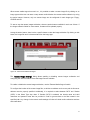
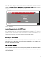
Firmware Update
The Firmware Update tool allows updating the firmware of available components present in your TSM.
There are two available options to update the firmware:
•
Upload a firmware bundle: upload a firmware bundle file from your computer to TSM and then start
the update.
•
Select a network location for a firmware update bundle: use this option to copy a firmware bundle file
available in your network.
The TSM will restart after one of the above options is performed and all TSM connections will be
interrupted.
Please power on the host if the TSM shows 'N/A' in BIOS version information after performing either
firmware update, factory reset or if TSM has just been turned on.
It is important to note that any kind of downgrade is not supported by TSM.
To avoid problems during firmware update, do not open a new TSM session in the same browser.
Figure 33. Firmware Update Mode Select
Upload a firmware bundle
This simple option is useful to upload a firmware update bundle file from your computer to TSM. After the
upload succeeds, you will be able to revise all updates available in the file.
50
Figure 34. Firmware Update
Select a network location for firmware bundle
The user can copy a firmware update bundle file to a network location and provide the TSM with this
location to update the TSM. Network location, credentials, IP address, path and file name are required for
this.
It is possible to reach the network location where the firmware update bundle file resides using one of the
supported network protocols: Samba (CIFS), NFS and TFTP. If Samba (CIFS) is selected, credentials will
be required to grant access to the network path.
After configuring the network path and clicking Apply, the firmware update bundle file will be transferred to
TSM and you will be able to review all updates available in the file.
Reviewing and applying available updates
After the transfer of the firmware update bundle file to TSM is completed, a new dialog is presented
containing a list of the available updates for the components so that you can review which components
will be updated. Clicking 'Apply' will start the firmware update whereas clicking 'Cancel' will exit the
firmware update.
51
As soon as the firmware update starts, TSM displays the current status of the firmware update. Each
component listed here has its own status, which can be 'Pending', 'Success', 'Failure' or 'In progress'. The
status of the components is automatically updated every 30 seconds.
While the firmware update is in progress, please do not remove the power cord or network cable from the
ThinkServer.
The 'Discard Pending Updates' button will cancel all the pending updates, but it will not cancel updates in
progress or roll back updated components to a previous version.
When all updates are completed or canceled, the message at the top of the dialog will inform that the
update process is finished.
Figure 35. Available Updates
Backup and Restore
The Configuration Backup and Restore tool allows to back up the settings from TSM or restore settings
previously saved according customer requirement. Please, refer to the Backup and Restore Features
Table in this document to view the supported features about Backup and Restore function. When
accessing the feature, two options will be presented: Backup Configuration and Restore Configuration.
The Backup Configuration option allows backing up the whole TSM configuration. It may take a few
minutes to complete and, after it finishes, a link will be provided to download the configuration file. By
default, the configuration file generated by TSM is named 'config.bak'.
52
The Restore Configuration option can be used to restore the TSM settings from a configuration file
previously saved. The restore operation requires the TSM to be rebooted and, after that, you will need to
log in again.
Figure 36. Configuration Backup and Restore
Table 10. Backup and Restore Features Table:
Entity
Active Directory
Network
Description
Configure the Active Directory Server Settings
Configuring the services in the BMC, network configuration and
network bonding configuration for the network interfaces.
DNS
Configure the DNS and Dynamic DNS update utility used to submit Dynamic DNS Update
requests to a name server.
DHCP mode
Configure the devices that are connected to a network (known as hosts) so they can
communicate on that network using the internet (IP).
VLAN Tag
NCSI Config
Misc
Serial Config
PEF Config
To configure the VLAN settings
To configure Network Controller Sideband Interface (NCSI) configuration settings.
Configure the auto negotiations, speed, duplex and mtu.
Serial configuration like authentication, and channel configuration
Configuring the BMC to take selected actions on event messages that it receives or has
internally generated
Notification setting
BIOS
Thermal & Power control
Debug Flags
NTP Client
Email Configurations
Boot order settings
To allow selection of the Thermal Profiles
Enable/Disable the RAWCommandLog and debug flag
Configure the synchronizing the clocks of computer systems over packet-switched, variable53
latency data networks.
LDAP config
Configure the application protocol for querying and modifying data of directory services
implemented in Internet Protocol (IP) networks.
User Account
User information and password encryption. To configure the PAM ordering for user
authentication into the BMC.
Session Timeout
Configuring the services running in the BMC
BMC
It holds the ipmipar information
DCMI
Data Center Manageability Interface
Images Redirection
KVM
Log Files
Mouse Mode
Password
RADIUS
Uploading an image into BMC or mounting the image from the remote media server
Used to auto video record configurations
Configure the list of system logs and audit logs occurred in this device.
Handles mouse emulation from local window to remote screen
User authentication
Provides centralized authentication, authorization and accounting management for computers
that connect in a network.
SSH
Secure Shell is cryptographic network protocol for secure data communication, remote
command-line login, remote command exection.
WatchDogTimer
HPM
Hostname
MAC
Lenovo SW
WDT is an electronic timer that is used to detect and recover from computer malfunctions.
Configure the hpm components
Host name.
Machine physical address
256 bytes of binary data
Platform config
Only in special cases this will be set as default instead of Default Lenovo config
Lenovo config
It is a default config file available from Lenovo factory. It will be used when user sets reset to
default
Software Interface
It has hardware key. Based on data on the HW we will control whether to enable WSMAN, KVM
etc
FRU
To get the firmware inventory list
Hardware Inventory List
Show hardware Inventory
Firmware Inventory List
Show firmware Inventory
SDR
It has sensor based information.
SEL
Configuring the system event logs.
54
Serial Over LAN
The Serial Over LAN allows user to configure the serial output so that TSM can be remotely viewed over
the LAN. It is possible to activate or deactivate Serial Over LAN and configure baud rate, flow control
configuration and DTR hang up state.
Baud Rate is the number of symbols per second transferred. Valid values are '9600', '19200', '38400',
'57600' and '115200'.
Hardware Flow Control is the process of managing the rate of data transmission between two nodes to
prevent a fast sender from overwhelming a slow receiver. It is possible to enable or disable Hardware
Flow Control in the Serial Over LAN settings.
Finally, the DTR Hang Up, when activated, turns off the computer's DTR (Data Terminal Ready) signal for
a period of time.
Figure 37. Serial Over LAN
55
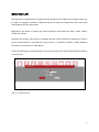
Chapter 6. Force Recover BIOS from TSM
If the server’s power is removed while the BIOS is being updated, the server might not restart correctly. If
this happens, perform the following procedure to recover from the BIOS update failure.
1. Disconnect all power cords from electrical outlets and disconnect all cables that are connected to the
server.
3. If the server is installed in a rack cabinet, remove the server from the rack cabinet and place it on a flat,
clean, and static-protective surface.
4. Remove the server cover.
5. Locate the BIOS recovery jumper on the system board. See “System board jumpers” in “ThinkServer
User Guide and Hardware Maintenance Manual”.
6. Move the BIOS recovery jump to the BIOS recovery position.
7. Connect the server to an AC power source and then the server will power on and then power off again.
Remove and replace the BIOS recovery jumper to its original position and wait for approximately 10
minutes. Once the recovery process completes, your server will automatically turn on.
8. Power off your server, reinstall any parts and reconnect any cables. Then, reinstall the server cover.
9. Connect the server to an AC power source and turn on the server. The BIOS settings recover to the
factory default settings. You need to check and configure the BIOS settings for your specific needs.
Note: If you cannot recover the BIOS after using the instructions in this topic, the BIOS ROM might be
damaged and you may need to replace the system board. Contact the Lenovo Customer Support Center.
56
Appendix A.
Notices
Lenovo may not offer the products, services, or features discussed in this document in all
countries. Consult your local Lenovo representative for information on the products and
services currently available in your area. Any reference to a Lenovo product, program, or
service is not intended to state or imply that only that Lenovo product, program, or
service may be used. Any functionally equivalent product, program, or service that does
not infringe any Lenovo intellectual property right may be used instead. However, it is the
user's responsibility to evaluate and verify the operation of any other product, program, or
service.
Lenovo may have patents or pending patent applications covering subject matter
described in this document. The furnishing of this document does not give you any license
to these patents. You can send license inquiries, in writing, to:
Lenovo
(United
States),
Inc. 1009
Think
Place Building
One
Morrisville,
NC 27560
U.S.A.
Attention: Lenovo Director of Licensing
LENOVO PROVIDES THIS PUBLICATION “AS IS” WITHOUT WARRANTY OF ANY
KIND, EITHER EXPRESS OR IMPLIED, INCLUDING, BUT NOT LIMITED TO, THE
IMPLIED WARRANTIES OF NON-INFRINGEMENT,MERCHANTABILITY OR FITNESS
FOR A PARTICULAR PURPOSE. Some jurisdictions do not allow disclaimer of express or
implied warranties in certain transactions, therefore, this statement may not apply to you.
This information could include technical inaccuracies or typographical errors. Changes are
periodically made to the information herein; these changes will be incorporated in new
editions of the publication. Lenovo may make improvements and/or changes in the
product(s) and/or the program(s) described in this publication at any time without notice.
The products described in this document are not intended for use in implantation or other
life support applications where malfunction may result in injury or death to persons. The
information contained in this document does not affect or change Lenovo product
specifications or warranties. Nothing in this document shall operate as an express or
implied license or indemnity under the intellectual property rights of Lenovo or third parties.
All information contained in this document was obtained in specific environments and is
presented as an illustration. The result obtained in other operating environments may vary.
Lenovo may use or distribute any of the information you supply in any way it believes
appropriate without incurring any obligation to you.
57
Any references in this publication to non-Lenovo Web sites are provided for convenience
only and do not in any manner serve as an endorsement of those Web sites. The materials
at those Web sites are not part of the materials for this Lenovo product, and use of those
Web sites is at your own risk.
Any performance data contained herein was determined in a controlled environment.
Therefore, the result obtained in other operating environments may vary significantly.
Some measurements may have been made on development-level systems and there is no
guarantee that these measurements will be the same on generally available systems.
Furthermore, some measurements may have been estimated through extrapolation. Actual
results may vary. Users of this document should verify the applicable data for their specific
environment.
58
Trademarks
Lenovo, the Lenovo logo, and ThinkServer are trademarks of Lenovo in the United
States, other countries, or both.
Windows is a trademark of the Microsoft group of companies.
Other company, product, or service names may be trademarks or service marks of others.
59