1
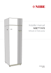
Installer manual
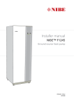
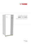
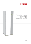
NIBE™ F1245
UK 1x230V
Ground source heat pump
LEK
IHB GB 1108-1
431076
4XLFN JXLGH
1DYLJDWLRQ
2N EXWWRQ FRQILUPVHOHFW
%DFN EXWWRQ EDFNXQGRH[LW
&RQWURO NQRE PRYHLQFUHDVHUHGXFH
A detailed explanation of the button functions can be found on page 39.
How to scroll through menus and make different settings is described on page 41.
6HW WKH LQGRRU FOLPDWH
;
The mode for setting the indoor temperature is reached, when in the start mode in the main menu, by pressing the
OK button twice. Read more about the settings on page 43.
,QFUHDVH KRW ZDWHU YROXPH
;
;
To temporarily increase the amount of hot water, first turn the control knob to mark menu 2 (water droplet) and then
press the OK button twice. Read more about the settings on page 50.
In event of disturbances in comfort
If a disturbance in comfort of any type occurs there are some measures that can be taken before you need to contact
your installer. See page 70 for instructions.
Table of Contents
1 Important information
Safety information
2 Delivery and handling
Transport
Assembly
Supplied components
Removing the covers
Removing parts of the insulation
2
2
5
5
5
6
6
7
Preparations
Filling and venting
Start guide
Post adjustment and venting
25
25
26
36
7 Control - Introduction
39
Display unit
Menu system
39
40
8 Control - Menus
3 The heat pump design
General
Electrical cabinets
Cooling section
4 Pipe connections
General
Dimensions and pipe connections
Brine side
Heating medium side
Hot water heater
Docking alternatives
5 Electrical connections
General
Connections
Settings
Optional connections
Connecting accessories
6 Commissioning and adjusting
NIBE™ F1245
8
8
9
11
43
Menu 1 - INDOOR CLIMATE
Menu 2 - HOT WATER
Menu 3 - INFO
Menu 4 - HEAT PUMP
Menu 5 - SERVICE
43
50
52
53
57
12
12
14
14
15
16
16
9 Service
63
Service actions
63
10 Disturbances in comfort
70
Info-menu
Manage alarm
Troubleshooting
70
70
70
11 Accessories
72
12 Technical data
73
18
18
20
21
22
24
25
Dimensions and setting-out coordinates
Technical specifications
Item register
73
74
77
Table of Contents |
1
1 Important information
Safety information
This manual describes installation and service procedures
for implementation by specialists.
This appliance is not intended for use by persons (including children) with reduced physical, sensory or mental
capabilities, or lack of experience and knowledge, unless
they have been given supervision or instruction concerning use of the appliance by a person responsible for their
safety.
Children should be supervised to ensure that they do not
play with the appliance.
Rights to make any design or technical modifications are
reserved.
©NIBE 2011.
Symbols
Serial number
The serial number can be found at the bottom right of
the front cover and in the info menu (menu 3.1).
6HULDO QXPEHU
Caution
Always give the product's serial number when
reporting a fault.
Country specific information
NOTE
Installer manual
This symbol indicates danger to machine or
person.
This installer manual must be left with the customer.
Great Britain
Caution
This symbol indicates important information
about what you should observe when maintaining your installation.
This installation is subject to building regulation approval,
notify the local Authority of intention to install.
Use only manufacturer’s recommended replacement
parts.
TIP
This symbol indicates tips on how to facilitate
using the product.
Benchmark places responsibilities on both manufacturers
and installers. the purpose is to ensure that customers
are provided with the correct equipment for their needs,
that it is installed, commissioned and serviced in accordance with the manufacturers instructions by competent
persons and that it meets the requirements of the appropriate Building Regulations. The Benchmark Checklist can
be used to demonstrate compliance with Building Regulations and should be provided to the customer for future
reference.
Installers are required to carry out the installation, commissioning and servicing work in accordance with the
Benchmark Code of practice which is available from the
Heating and Hotwater Industry Council who manage and
promote the Scheme. Visit www.centralheating.co.uk for
information.
Warranty information
Thank you for installing a new NIBE heat pump in your
home.
NIBE heat pumps are manufactured in Sweden to the
very highest standard so we are pleased to offer our
customers a comprehensive guarantee.
2
Chapter 1 | Important information
NIBE™ F1245
The product is guaranteed for 24 months for parts and
labour from the date of installation or 33 months from
the date of manufacture, whichever is the shorter.
The NIBE guarantee is based on the unit being installed
and commissioned by a NIBE accredited installer, serviced
every year and the Benchmark documents completed.
Where this condition is not met, any chargeable spare
parts or components issued within the applicable guarantee period still benefit from a 12 month warranty from
the date of issue by the manufacturer.
We recommend the installer completes and returns as
soon as possible, your guarantee registration card or
completes the guarantee form on the NIBE website
www.nibe.co.uk.
Electrical Supply
The heat pump must be permanently connected to a
230V ac 50Hz supply.
All system components shall be of an approved type and
all wiring to current I.E.E wiring regulations.
External wiring must be correctly earthed, polarised and
in accordance with the relevant standards: Currently this
is BS 7671.
Domestic Hot Water
All domestic hot water circuits, connections and fittings
must be in accordance with the relevant standards and
water supply regulations. It should also be in accordance
with the relevant requirements of the Local Authority and
the Building Regulations relevant to the location of installation.
BS 6700 Services supplying water for domestic use within
buildings and their cartilages.
Water Supply (Water Fitting) Regulations 1999 or The
Water Bylaws 2000 (Scotland).
Heating System
The installation of the heat pump should follow best
practice as covered in the following:
BS 5449 Forced circulation hot water central heating
systems for domestic premises.
BS 15450 Heating systems in buildings – Design of heat
pump heating systems.
NIBE™ F1245
Chapter 1 | Important information
3
Inspection of the installation
Current regulations require the heating installation to be inspected before it is commissioned. The inspection must be
carried out by a suitably qualified person. Fill in the page for information about installation data in the User manual.
✔
Description
Notes
Signature Date
Brine (page 14)
System flushed
System vented
Antifreeze
Level/Expansion vessel
Particle filter
Safety valve
Shut off valves
Circulation pump setting
Heating medium (page 15)
System flushed
System vented
Expansion vessel
Particle filter
Safety valve
Shut off valves
Circulation pump setting
Electricity (page 18)
Fuses heat pump
Fuses property
Outside sensor
Room sensor
Safety breaker
Earth circuit-breaker
Setting of emergency mode thermostat
Miscellaneous
Warranty
Benchmark checklist
4
Chapter 1 | Important information
NIBE™ F1245
2 Delivery and handling
Installation area
Transport
F1245 should be transported and stored vertically in a
dry place. When being moved into a building, F1245 may
be leant back 45 °. Note! Can be tail heavy.
0
R
Leave a space of 800 mm in front of the heat pump.
Approx 50 mm free space is required in order to open
the side hatches. The hatches do not need to be opened
during service, all service on F1245 can be carried out
from the front. Leave space between the heat pump and
wall behind (and any routing of supply cables and pipes)
to reduce the risk reproduction of any vibration.
(50) R
0
(50)
Pulling out the cooling module
To simplify transport and service, the heat pump can be
separated by pulling the cooling module out from the
cabinet.
* A normal installation needs 300 - 400 mm (any side) for connection equipment, i.e. level vessel, valves and electrical equipment.
See page 65 for instructions about the separation.
Assembly
႑
Position the heat pump on a firm base that can bear
its weight, preferably on a concrete floor or foundation. Use the heat pump’s adjustable feet to obtain
a horizontal and stable set-up.
30 - 50 mm
႑
The area where the heat pump is located must be
equipped with floor drainage.
႑
Install with its back to an outside wall, ideally in a
room where noise does not matter, in order to eliminate noise problems. If this is not possible, avoid
placing it against a wall behind a bedroom or other
room where noise may be a problem.
႑
Wherever the unit is located, walls to sound sensitive
rooms should be fitted with sound insulation.
႑
Route pipes so they are not fixed to an internal wall
that backs on to a bedroom or living room.
NIBE™ F1245
Chapter 2 | Delivery and handling
5
Supplied components
Removing the covers
Front cover
2
Outside sensor
Particle filter
Room sensor
1
LEK
LEK
O-rings
LEK
Safety valve
(0.3 MPa) (3 bar)
LEK
Level vessel
LEK
LEK
K
1. Remove the screws from the lower edge of the front
LE
cover.
Tundish (WM3)
2. Lift the cover out at the bottom edge and up.
Side covers
LEK
Expansion vessel
Armoured hose
domestic water (expansion vessel)
with holder (CM4,
supplied separately)
LE
K
LE
K
Cold water shut-off Pressure reduction
and pressure safety
valve (QN17)
Filler valve, climate
valve,
system (QM11) water heater (FL1)
Conex connectors Filler hose (WN1)
5-8 kW
2 x (ø28 x G25)
2 x (ø22 x G20)
12 kW
4 x (ø28 x G25)
LEK
LEK
LEK
LEK
The side covers can be removed to facilitate the installation.
1.
2.
3.
4.
5.
Remove the screws from the upper and lower edges.
Twist the cover slightly outward.
Move the cover backwards and slightly to the side.
Pull the cover to one side.
Pull the cover forwards.
Location
The kit of supplied items is placed in packaging on top
of the heat pump.
6
Chapter 2 | Delivery and handling
NIBE™ F1245
Removing parts of the insulation
Insulation, immersion heater
NOTE
Electrical installation and service must be carried
out under the supervision of a qualified electrician. Electrical installation and wiring must be
carried out in accordance with the stipulations
in force.
Parts of the insulation can be removed to facilitate the
installation.
Insulation, top
1. Disconnect the cable from the motor and remove
the motor from the shuttle valve as illustrated.
1. Remove the cover of the junction box according to
the description on page 19.
2. Grip the handle and pull the insulation carefully to-
A
wards you as illustrated.
LEK
LEK
B
LE
K
2. Grip the handle and pull straight out as illustrated.
LE
K
LE
K
NIBE™ F1245
Chapter 2 | Delivery and handling
7
3 The heat pump design
Pipe connections
General
;/
;/
;/
;/
;/
;/
40
%7
8%
XL 1
XL 2
XL 3
XL 4
XL 5
XL 6
XL 7
Connection, heating medium flow
Connection, heating medium return
Connection, cold water
Connection, hot water
Connection, HWC
Connection, brine in
Connection, brine out
41
%7
$$
HVAC components
6)
FL 5
QM 22
QM 32
QM 33
QM 34
QN 10
WP 4
$$;-
$$;-
(%
T&P valve
Venting, coil
Shut off valve, heating medium return
Shut off valve, brine out
Shut-off valve, brine in
Shuttle valve, climate system/water heater
Pipe connection, heating medium flow
3)
Sensors etc.
3)
%7
8%
8%
40
BT 1
BT 2
BT 6
BT 7
Outside sensor
Temperature sensors, heating medium flow
Temperature sensor, hot water charging
Temperature sensor, hot water top
:3
40
40
Electrical components
AA 4
Display unit
AA4-XJ3 USB outlet (no function)
3)
EB 1
SF 1
AA4-XJ4 Service outlet (No function)
Immersion heater
Switch
Miscellaneous
View from above
)/
;/
%7
PF 1
PF 2
PF 3
UB 1
UB 2
UB 3
Rating plate
Type plate, cooling section
Serial number plate
Cable gland, incoming electricity
Cable gland
Cable gland, rear side, sensor
Designations in component locations according to
standard IEC 81346-1 and 81346-2.
8
Chapter 3 | The heat pump design
NIBE™ F1245
Electrical cabinets
)'
)'
$$
$$
)$
$$
)%
Electrical components
AA 1
AA 2
AA 3
FA 1
FB 1
FD 1
FD 2
Immersion heater card
Base card
Input circuit board
Miniature circuit-breaker
Motor cut-out*
Temperature limiter/Emergency mode thermostat
Temperature limiter, compressor
NIBE™ F1245
* 1x230 V has auxiliary switch for motor cut-out.
Designations in component locations according to
standard IEC 81346-1 and 81346-2.
Chapter 3 | The heat pump design
9
;
)%
4$
;
&$
1x230 V 5-12 kW
Electrical components
CA 1
FB 1
QA 30
X 301
X 302
Capacitor
Motor cut-out*
Soft-starter
Terminal block
Terminal block
* 1x230 V has auxiliary switch for motor cut-out.
Designations in component locations according to
standard IEC 81346-1 and 81346-2.
10
Chapter 3 | The heat pump design
NIBE™ F1245
Sensors etc.
Cooling section
%7
%7
$$
*3
*3
%7
40
Electrical components
40
AA 100 Joint card
EB 10 Compressor heater
Cooling components
(3
%7
*4
%7
+6
%3
%7
;/
%3
41
(%
High pressure pressostat
Low pressure pressostat
Temperature sensors, heating medium return
Temperature sensor, brine in
Temperature sensor, brine out
Temperature sensor, condenser supply line
Temperature sensor, hot gas
Temperature sensor, fluid pipe
Temperature sensor, suction gas
%7
[9 N:
(3
BP 1
BP 2
BT 3
BT 10
BT 11
BT 12
BT 14
BT 15
BT 17
EP 1
EP 2
GQ 10
HS 1
QN 1
Evaporator
Condenser
Compressor
Drying filter
Expansion valve
Designations in component locations according to
standard IEC 81346-1 and 81346-2.
;/
[9 N:
(3
(3
%7
*4
%7
+6
%3
%7
;/
%3
41
(%
;/
Pipe connections
XL 20
XL 21
Service connection, high pressure
Service connection, low pressure
HVAC components
GP 1
GP 2
QM 1
QM 2
Circulation pump
Brine pump
Drainage, climate system
Draining, brine side
NIBE™ F1245
Chapter 3 | The heat pump design
11
4 Pipe connections
General
Pipe installation must be carried out in accordance with
current norms and directives. F1245 can operate with a
return temperature of up to 58 °C and an outgoing
temperature from the heat pump of 70 (65 °C with only
the compressor).
F1245 is not equipped with external shut off valves; these
must be installed to facilitate any future servicing.
NOTE
The pipe system needs to be flushed out before
the heat pump is connected so that debris cannot damage component parts.
damage. This is the only thing the non-pressurised overflow pipe may be used for. Even overflow pipes from
tundish (WM3) connected to the pressure reduction valve
(FL1, safety valve) must be connected to the drain in the
same way.
Discharge pipes from tundishes shall have av vertical
section of pipe at least 300 mm long, before any elbows
or bends in the pipework (see following picture).
Metal discharge pipe from
temperature relief valve to tundish.
Safety device
(e.g. temperature
relief valve).
500 mm maximum
Tundish
300 mm
minimum
Discharge below
fixed grating.
NOTE
This installation is subject to building regulation
approval, notify the local Authority of intention
to install.
Metal discharge pipe from tundish,
with continous fall.
Fixed grating
Trapped gulley
Possible wall
NOTE
Use only manufacturer’s recommended replacement parts.
Table sizing of copper discharge pipe for common temperature relief valve outlet sizes.
Hard water areas
Waste water from the collection tray at the evaporator
and from the safety valve is led by a non-pressurised
overflow pipe to the drain so that hot water cannot cause
Valve outlet size
G1/2
G1/2
G1/2
<G3>/4
<G3>/4
<G3>/4
G1
G1
G1
12
Usually, there should not be a problem in installing F1245
in areas of hard water as the maximum operating temperature is 60 °C.
Minimum size of dis- Minimum size of dis- Maximum resistance
charge pipe
charge pipe from
allowed, expressed
tundish
as a lenght of
straight pipe (i.e. no
elbows or bends)
15 mm
15 mm
15 mm
22 mm
22 mm
22 mm
28 mm
28 mm
28 mm
Chapter 4 | Pipe connections
22 mm
28 mm
35 mm
28 mm
35 mm
42 mm
35 mm
42 mm
54 mm
up to 9 m
up to 18 m
up to 27 m
up to 9 m
up to 18 m
up to 27 m
up to 9 m
up to 18 m
up to 27 m
Resistance created by
each elbow or bend
0.8 mm
1.0 mm
1.4 mm
1.0 mm
1.4 mm
1.7 mm
1.4 mm
1.7 mm
2.3 mm
NIBE™ F1245
Symbol key
;/
;/
;/
;/
;/
;/
Symbol Meaning
Venting valve
Shut-off valve
Non-return valve
Shunt / shuttle valve
Safety valve
Trim valve
Tundish
Temperature sensor
Level vessel
P
Pressure gauge
Circulation pump
Particle filter
Auxiliary relay
Fan
Compressor
Heat exchanger
System diagram
F1245 consists of a heat pump, water heater, electrical
module, circulation pumps and a control system. F1245
is connected to the brine and heating medium circuits.
XL 1
XL 2
XL 3
XL 4
XL 6
XL 7
Connection, heating medium flow
Connection, heating medium return
Connection, cold water
Connection, hot water
Connection, brine in
Connection, brine out
In the heat pump evaporator, the brine (water mixed with
anti-freeze, glycol or ethanol) releases its energy to the
refrigerant, which is vaporised in order to be compressed
in the compressor. The refrigerant, of which the temperature has now been raised, is passed to the condenser
where it gives off its energy to the heating medium circuit
and, if necessary, to the water heater. If there is a greater
need for heating/hot water than the compressor can
provide there is an integrated immersion heater.
NIBE™ F1245
Chapter 4 | Pipe connections
13
1775
25-50
650*
650*
Type
Surface soil heat,
recommended collector length (m)
Rock heat, recommended active
drilling depth (m)
5 kW
8 kW
12 kW
200-300
325-2x250
2x250-2x350
70-90
120-145
180-210
Applies to PEM hose 40x2.4 PN 6.3.
Caution
The length of the collector hose varies depending on the rock/soil conditions, climate zone and
on the climate system (radiators or underfloor
heating).
440
600
525
470
390
210
130
Max length per coil for the collector should not exceed
400 m.
50
25
In those cases where it is necessary to have several collectors, these should be connected in parallel with the possibility for adjusting the flow of the relevant coil.
620
430
;/
Collector
These are rough example values. At installation the correct
calculations must be made according to local conditions.
560
;/
Brine side
75
70
Dimensions and pipe connections
;/
For surface soil heat, the hose should be buried at a depth
determined by local conditions and the distance between
the hoses should be at least 1 metre.
;/
;/
;/
For several bore holes, the distance between the holes
must be determined according to local conditions.
Ensure the collector hose rises constantly towards the
heat pump to avoid air pockets. If this is not possible,
airvents should be used.
Pipe dimensions
Connection
5-8
kW
(XL6)/(XL7) Brine in/out ext Ø
(mm)
(XL1)/(XL2) Heating medium
flow/return ext Ø
(mm)
(XL3)/(XL4) Cold/hot water Ø
(mm)
12
kW
28
22
28
As the temperature of brine system can fall below 0 °C
it must be protected against freezing down to -15 °C. 1
litre of ready mixed brine per meter of collector hose
(applies when using PEM-hose 40x 2.4 PN 6.3) is used as
a guide value when making the volume calculation.
Anti freeze must be mixed according to manufacturer's
instructions to ensure frost protection and should be
checked using a refractometer.
NOTE
22
Ensure that cleaning agent has been removed
from the entire system before the anti-freeze is
added.
NIBE Energy Systems Limited recommends water treatments (supplied by e.g. Fernox and Sentinel) specifically
designed for heat pumps.
* Can be angled for side connection.
14
Chapter 4 | Pipe connections
NIBE™ F1245
Side connection
Heating medium side
It is possible to angle the brine connections, for connection to the side instead of top connection.
To angle out a connection:
1. Disconnect the pipe at the top connection.
2. Angle the pipe in the desired direction.
3. If necessary, cut the pipe to the desired length.
Connecting the climate system
A climate system is a system that regulates indoor comfort
with the help of the control system in F1245 and for example radiators, underfloor heating/cooling, fan convectors etc.
႑
Install all required safety devices, shut-off valves (as
close to the heat pump as possible), and supplied
particle filter.
႑
The safety valve must have a maximum 0.25 MPa (2.5
bar) opening pressure and be installed on the heating
medium return as illustrated. The entire length of the
overflow water pipe from the safety valves must be
inclined to prevent water pockets and must also be
frost proof.
႑
When connecting to a system with thermostats on
all radiators, a relief valve must be fitted, or some of
the thermostats must be removed to ensure sufficient
flow.
Connecting the brine side
႑
Insulate all indoor brine pipes against condensation.
႑
The level vessel must be installed as the highest point
in the brine system on the incoming pipe before the
brine pump (Alt. 1).
If the level vessel cannot be placed at the highest point
an expansion vessel must be used (Alt. 2).
NOTE
Note that condensation may drip from the level
vessel. Position the vessel so that this does not
harm other equipment.
႑
Details of the antifreeze used must be shown on the
level vessel.
႑
Install the supplied safety valve under the level vessel
as illustrated. The entire length of the overflow water
pipe from the safety valves must be inclined to prevent
water pockets and must also be frost proof.
႑
Install shut off valves as close to the heat pump as
possible.
႑
Fit the supplied particle filter on the incoming pipe.
In the case of connection to an open groundwater system,
an intermediate frost-protected circuit must be provided,
because of the risk of dirt and freezing in the evaporator.
This requires an extra heat exchanger.
$OW Before installing the heat pump in an existing system, it
is important that the system is properly flushed through.
Even if the heat pump is to be installed in a new system,
the heat pump and system should be flushed.
NOTE
Ensure that cleaning agent has been removed
from the entire system before adding inhibitor.
After flushing an inhibitor should be used for long-term
anti-corrosion protection.
NIBE Energy Systems Limited recommends water treatments (supplied by e.g. Fernox and Sentinel) specifically
designed for heat pumps.
$OW 40;/
:1
P
P
40
;/
41
)/
&0
&ROOHFWRU
;/
)/
:0
;/
NIBE™ F1245
;/
;/
;/
Chapter 4 | Pipe connections
15
Ventilation recovery
Hot water heater
Connecting the hot water heater
The installation can be supplemented with the exhaust
air module FLM to provide ventilation recovery.
႑
The hot water heater in the heat pump must be supplied with necessary set of valves.
႑
Pipes and other cold surfaces must be insulated with
diffusion-proof material to prevent condensation.
႑
The mixing valve must be installed if the setting is
changed so that the temperature can exceed 60 °C.
The setting is made in menu 5.1.1 (page 58)
႑
The brine system must be supplied with a pressure
expansion vessel (CM3). If there is a level vessel (CM2)
this should be replaced.
႑
The safety valve must have a maximum 1.0 MPa (10.0
bar) opening pressure and be installed on the incoming domestic water line as illustrated. The entire length
of the overflow water pipe from the safety valves must
be inclined to prevent water pockets and must also
be frost proof.
([WUDFW
DLU
Avluft
Ø 160
([KDXVW
DLU
Frånluft
Ø 160
)/0
NOTE
P
Please note that the connection of the T&P-valve
should not be used for any other purpose.
Valves may not be positioned between the expansion valve and the water heater.
Docking alternatives
F1245 can be connected in several different ways, some
of which are shown below.
Further option information is available at www.nibe.co.uk
and in the respective assembly instruction for the accessory used. See page 72 move the list of the accessories
that can be used to F1245.
Free cooling
The installation can be supplemented with fan convectors,
for example, in order to allow connections for free cooling
(PCS 44).
Buffer vessel
႑
If the climate system volume is too small for the heat
pump output, the radiator system can be supplemented
with a buffer vessel, for example NIBE UKV.
Pipes and other cold surfaces must be insulated with
diffusion-proof material to prevent condensation.
႑
Where the cooling demand is high, fan convectors
with drip trays and drain connection are needed.
႑
The brine system must be supplied with a pressure
expansion vessel (CM3). If there is a level vessel (CM2)
this should be replaced.
UKV
P
)DQ FRQYHFWRUV
Fläktkonvektor
P
2
1
16
Chapter 4 | Pipe connections
3
NIBE™ F1245
Under floor heating systems
Ground water system
The external circulation pump is dimensioned for the
under floor heating system’s demand.
An intermediate heat exchanger is used to protect the
heat pump's exchanger from dirt. The water is released
into a buried filtration unit or a drilled well. See page 23
for more information about connecting a ground water
pump.
If the climate system volume is too small for the heat
pump output, the underfloor heating system can be
supplemented with a buffer vessel, for example NIBE
UKV.
UKV
P
Pool
Two or more climate systems
When more than one climate system, with a lower temperature, is to be heated up, the following connection
can be used. The shunt valve lowers the temperature to,
for example, the under floor heating system.
Charging of the pool is controlled by the pool sensor. In
the case of low pool temperatures, the shuttle valve reverses direction and opens towards the pool exchanger.
The POOL 40 accessory is required for this connection.
The ECS 40/ECS 41 accessory is required for this connection.
Pool
NIBE™ F1245
Chapter 4 | Pipe connections
17
5 Electrical connections
General
All electrical equipment, except the outdoor sensors,
room sensors and the current sensors are ready connected
at the factory.
႑
Disconnect the heat pump before insulation testing
the house wiring.
႑
If the building is equipped with an earth-fault breaker,
F1245 should be equipped with a separate one.
႑
If a miniature circuit breaker is used this should have
at least motor characteristic “C”. See page 74 for
fuse size.
႑
For wiring diagrams for the heat pump, see separate
installation handbook for wiring diagrams.
႑
Communication and sensor cables to external connections must not be laid close to high current cables.
႑
The minimum area of communication and sensor
cables to external connections must be 0.5 mm² up
to 50 m, for example EKKX or LiYY or equivalent.
႑
When cable routing in F1245, cable grommets (e.g.
UB1-UB3, marked in image) must be used. In UB1-UB3
the cables are inserted through the heat pump from
the back to the front.
Resetting
The temperature limiter (FD1) is accessible behind the
front cover. Reset the temperature limiter by pressing the
button (FD1-SF2) using a small screwdriver.
Temperature limiter, compressor
The temperature limiter (FD2) cuts the current supply to
the soft starter if the temperature rises above 88 °C and
is manually reset.
Resetting
The temperature limiter (FD2) is accessible behind the
front cover. Reset the temperature limiter by pressing the
button (FD2-SF2) using a small screwdriver.
Motor cut-out
Motor protection breaker (FB1) cuts the power to the
compressor if the current is too high.
Resetting
The motor protection breaker (FB1) is accessible behind
the front cover. The breaker is reset by twisting the control knob to horizontal position.
Caution
Check the miniature circuit-breaker, temperature
limiter and motor protection breaker. They may
have tripped during transportation.
NOTE
The switch (SF1) must not be moved to " " or
" " until the boiler has been filled with water.
Otherwise the temperature limiter, thermostat,
compressor and the immersion heater can be
damaged.
)'
8%
)'
NOTE
)'6)
Electrical installation and service must be carried
out under the supervision of a qualified electrician. Cut the current with the circuit breaker
before carrying out any servicing. Electrical installation and wiring must be carried out in accordance with the stipulations in force.
)'6)
Miniature circuit-breaker
)$
8%
)%
The heat pump and a large proportion of its internal
components are internally fused by a miniature circuit
breaker (FA1).
8%
Temperature limiter
The temperature limiter (FD1) cuts the current supply to
the electrical addition if the temperature rises between
90 and 100°C and can be manually reset.
18
Chapter 5 | Electrical connections
NIBE™ F1245
Removing the cover, base board
Accessibility, electrical connection
The plastic cap of the electrical boxes is opened using a
screwdriver.
Caution
To remove the cover for the base board, the
cover for the input circuit board must first be
removed.
NOTE
The cover for the input card is opened without
a tool.
Removing the cover, input circuit board
1
LE
K
A
B
1
2
LE
K
1. Push the catch down.
2. Angle out the cover and remove it.
2
LE
K
Removing the cover, immersion heater circuit
board
A
1
B
1. Disconnect the switches using a screwdriver.
2. Insert the screwdriver (A) and pry the catch carefully
downwards (B).
3. Angle out the cover and remove it.
LE
K
2
1. Insert the screwdriver (A) and pry the catch carefully
downwards (B).
2. Angle out the cover and remove it.
NIBE™ F1245
Chapter 5 | Electrical connections
19
Cable lock
Outside sensor
Use a suitable tool to release/lock cables in the heat pump
terminal blocks.
Install the outside temperature sensor (BT1) in the shade
on a wall facing north or north-west, so it is unaffected
by the
morning sun.
Connect the sensor to terminal block X6:1 and X6:2 on
the input card (AA3). Use a 2 core cable of at least 0.5
mm² cable area.
3
2
1
2
$OW If a conduit is used it must be sealed to prevent condensation in the sensor capsule.
2
4
K
LE
2XWVLGH
Externt
1
3
$OW Connections
$$;
NOTE
To prevent interference, unscreened communication and/or sensor to external connections
cables must not be laid closer than 20 cm to
high voltage cable when cable routing.
Power connection
%7
If temperature sensor, external flow line (BT25) needs to
be used, connect it to terminal block X6:5 and X6:6 on
the input card (AA3). Use a 2 core cable of at least 0.5
mm² cable area.
)
F1245
1
2
3
4
5
6
7
8
9
Connection 1x230V
$$;
N
PE
0
$$;
L1
1
2
3
4
5
6
7
8
9
$$;
Temperature sensor, external flow line
F1245 must be installed via an isolator switch with a
minimum breaking gap of 3mm. Minimum cable area
must be dimensioned according to the fuse rating used.
Supplied cable for incoming electricity is connected to
terminal block X1 on the immersion heater card (AA1).
$$;
)
F1245
VHQVRU
%7
$$;
1
PE1
NOTE
F1245-12 contains scroll compressor, which
means that it is important that electrical connections are made with the correct phase sequence.
With the incorrect phase sequence, the compressor does not start and an alarm is displayed.
If separate supply to the compressor and immersion
heater is required, see section "Switch for external
blocking of addition and/or compressor" on page 22.
20
Chapter 5 | Electrical connections
NIBE™ F1245
Room sensor
Settings
F1245 is delivered with a room sensor supplied (BT50).
The room temperature sensor has up to three functions:
)'%7
1. Show current room temperature in the heat pump's
display.
$$6)
2. Option of changing the room temperature in °C.
3. Makes it possible to change/stabilise the room tem-
$$;
perature.
Install the sensor in a neutral position where the set
temperature is required. A suitable location is on a free
inner wall in a hall approx. 1.5 m above the floor. It is
important that the sensor is not obstructed from measuring the correct room temperature by being located, for
example, in a recess, between shelves, behind a curtain,
above or close to a heat source, in a draft from an external door or in direct sunlight. Closed radiator thermostats
can also cause problems.
The heat pump operates without the sensor, but if one
wishes to read off the accommodation's indoor temperature in F1245’s display the sensor must be installed.
Connect the room sensor to X6:3 and X6:4 on the input
circuit board (AA3).
If the sensor is to be used to change the room temperature in °C and/or to change/stabilise the room temperature, the sensor must be activated in menu 1.9.4.
If the room sensor is used in a room with under floor
heating it should only have an indicatory function, not
control of the room temperature.
5RRPRG
VHQVRU
05
$$;
Electrical addition - maximum output
On delivery the immersion heater is connected for a
maximum of 7 kW.
The immersion heater output is divided into seven steps,
according to the table below.
Setting max electrical output
Setting maximum output in the electrical addition is done
in menu 5.1.12.
The tables display the total phase current for the immersion heater.
1x230V
Max electrical addition (kW)
Max phase current L1(A)
0
1
2
3
4
5
6
7
0
4.3
8.7
13
17.4
21.7
26.1
30.4
)
F1245
1
2
3
4
5
6
7
8
9
$$;
$$;
Emergency mode
Caution
Changes of temperature in accommodation take
time. For example, short time periods in combination with underfloor heating will not give a
noticeable difference in room temperature.
NIBE™ F1245
When the heat pump is set to emergency mode (SF1 is
set to ) only the most necessary functions are activated.
႑
The compressor is off and heating is managed by the
immersion heater.
႑
Hot water is not produced.
Chapter 5 | Electrical connections
21
Optional connections
NOTE
Switch (SF1) must not be moved to " " or " "
until F1245 has been filled with water. Otherwise the temperature limiter, thermostat, compressor and the immersion heater can be damaged.
Power in emergency mode
The immersion heater’s output in emergency mode is set
with the dipswitch (S2) on the immersion heater circuit
board (AA1) according to the table below. Factory setting
is 6 kW.
1x230V
1 kW
2 kW
3 kW
4 kW
5 kW
6 kW
7 kW
1
2
3
4
5
6
off
off
off
off
on
on
on
off
off
off
off
off
off
off
off
on
on
on
on
on
on
off
off
off
off
off
off
off
off
off
off
on
off
on
on
on
off
on
off
on
off
on
External connection options
F1245 has software controlled inputs and outputs on the
input card (AA3), for connecting the extern switch function or sensor. This means that when an external switch
function or sensor is connected to one of six special
connections, the correct function must be selected to the
correct connection in the software in F1245.
Caution
If an external switch function or sensor is connected to F1245, the function to use input or output
must be selected in menu 5.4, see page 61.
Selectable inputs on the input card for these functions
are AUX1 (X6:9-10), AUX2 (X6:11-12), AUX3 (X6:13-14),
AUX4 (X6:15-16) and AUX5 (X6:17-18). Selectable outputs are AA3:X7.
VRIW LQRXWSXWV EORFN KHDWLQJ
DFWLYDWH WHPS OX[
1x230V
QRW XVHG
ON
1 2 3 4 5 6
QRW XVHG
QRW XVHG
DODUP RXWSXW
([WHUQDO
B
A
$$6)
The image shows the dip-switch (AA1-SF2) in the factory
setting, that is 6 kW.
$$;
)
9
10
11
12
13
14
15
16
$$;
Emergency mode thermostat
The supply temperature is set in emergency mode using
a thermostat (FD1-BT30). It can be set to 35 (pre-set, for
example underfloor heating) or 45 °C (for example radiators).
The example above uses the inputs AUX1 (X6:9-10) andAUX2
(X6:11-12) on the input circuit board (AA3).
Caution
Some of the following functions can also be activated and scheduled via menu settings.
K
LE
Possible selection for AUX inputs
Switch for external blocking of addition and/or
compressor
In those cases external blocking of addition and/or compressor is wanted, this can be connected to terminal block
22
Chapter 5 | Electrical connections
NIBE™ F1245
X6 on the input card (AA3), which is positioned behind
the front cover.
The additional heat and/or the compressor are disconnected by connecting a potential free switch function to the
input selected in menu 5.4, see page 61.
The value for the change is set in menu 1.9.2, "external adjustment".
႑
External adjustment for climate systems 2 to 4 require
accessories (ECS 40).
External blocking of addition and compressor can be
combined.
A closed contact results in the electrical output being
disconnected.
See the accessory’s installer handbook for installation
instructions.
Contact for activation of fan speed
Switch for external blocking of heating
Caution
In those cases external blocking of heat is used, this can
be connected to terminal block X6 on the input card
(AA3), which is positioned behind the front cover.
Heating operation is disconnected by connecting a potential free switch function to the input selected in menu
5.4, see page 61.
A closed switch results in blocked heating operation.
Switch for external forced control of brine pump
In those cases external forced control of brine pump is
used, this can be connected to terminal block X6 on the
input card (AA3), which is positioned behind the front
cover.
The brine pump can be force controlled by connecting a
potential free switch function to the input selected in
menu 5.4, see page 61.
A closed switch means that the brine pump is active.
Contact for activation of “temporary lux"
An external contact function can be connected to F1245
for activation of the hot water function“temporary lux".
The switch must be potential free and connected to the
selected input (menu 5.4, see page 61) on terminal block
X6 on the input circuit board (AA3).
"temporary lux" is activated for the time that the contact
is connected.
Contact for activation of “external adjustment"
An external contact function can be connected to F1245
to change the supply temperature and the room temperature.
When the switch is closed the temperature changes in
°C (if the room sensor is connected and activated). If a
room sensor is not connected or not activated, the desired
offset of "temperature" (heating curve offset) is set with
the number of steps selected. The value is adjustable
between -10 and +10.
႑
climate system 1
The switch must be potential free and connected to
the selected input (menu 5.4, see page 61) on terminal block X6 on the input circuit board (AA3).
NIBE™ F1245
climate system 2 to 4
The external contact function functions only if
the accessory FLM is installed and activated.
An external contact function can be connected to F1245
for activation of one of the four fan speeds. The switch
must be potential free and connected to the selected input (menu 5.4, see page 61) on terminal block X6 on the
input circuit board (AA3). When the switch closes, the
selected fan speed is activated. Normal speed is resumed
when the contact is opened again.
NV 10, pressure/level/flow monitor brine
If the level sensor (accessory NV10) is desired for the brine
installation it can be connected on the selected input
(menu 5.4, see page 61) on terminal block X6 on the input circuit board (AA3).
Pressure and flow sensors can also be connected to the
input.
For function the input must be connected during normal
operation.
Possible selection for AUX output (potential
free variable relay)
It is possible to have an external connection through the
relay function via a potential free variable relay (max 2
A) on the input circuit board (AA3), terminal block X7.
Optional functions for external connection:
႑
Indication of buzzer alarm.
႑
Controlling ground water pump.
႑
Cooling mode indication (only applies if accessories
for cooling are present or if the heat pump has the
integrated cooling function).
႑
Control of circulation pump for hot water circulation.
႑
External circulation pump (for heating medium).
႑
External, reversing valve for hot water.
If any of the above is installed to terminal block X7 it must
be selected in menu 5.4, see page 61.
The common alarm is preselected at the factory.
Chapter 5 | Electrical connections
23
Connecting accessories
NOTE
An accessory card is required if several functions
are connected to terminal block X7 at the same
time that the buzzer alarm is activated (see page
72).
Instructions for connecting accessories are in the installation instructions provided for the respective accessory.
See page 72 for the list of the accessories that can be
used with F1245.
& 12 1&
$$;
$$;
The picture shows the relay in the alarm position.
When switch (SF1) is in the " " or “
relay is in the alarm position.
” position the
External circulation pump, ground water pump or hot
water circulation pump connected to the buzzer alarm
relay as illustrated below.
NOTE
Mark up any junction boxes with warnings for
external voltage.
$$;
& 12 1&
F1X45
)
Externt
([WHUQDO
L
N
PE
L
N PE
$$;
&LUFXODWLRQ SXPS
Caution
The relay outputs can have a max load of 2 A
(230 V AC) in total.
24
Chapter 5 | Electrical connections
NIBE™ F1245
6 Commissioning and adjusting
Preparations
6. When the filling procedure is complete, remove the
1. Check that the switch (SF1) is in position " ".
2. Check that the temperature limiter FD1 has not
Venting
flexible hose (WN1).
tripped.
1. Bleed the heat pump via the bleed valve (QM22) and
the rest of the climate system via the relevant bleed
valves.
3. Check for water in the hot water heater and climate
system.
2. Keep topping up and venting until all air has been
removed and the pressure is correct.
Caution
Check the temperature limiter, motor protection
and miniature circuit-breaker. They may have
tripped during transportation.
TIP
If the heating medium pump (GP1) must be run
during venting, it can be started via the start
guide.
NOTE
At the time of commissioning, complete all relevant sections of the Benchmark Checklist located at the back of this document.
Completion of the Benchmark Checklist is a
condition of warranty. For full terms and conditions of warranty, please see our website
www.nibe.co.uk.
NOTE
The pipe from the coil in the container must be
drained of water before air can be released. This
means that the system is not necessarily vented
despite the flow of water when the venting valve
(QM22) is opened.
Filling the hot water heater
Filling and venting
1. Open a hot water tap in the house.
2. Fill the hot water heater through the cold water
Filling and venting the climate system
connection (XL3).
Filling
3. When the water that comes out of the hot water tap
is no longer mixed with air, the water heater is full
and the tap can be closed.
40;/
:1
P
Filling and venting the brine system
When filling the brine system, mix the water with antifreeze in an open container. The mixture should be protected against freezing down to about -15 °C. The brine
is filled by connecting a filling pump.
40
41
)/
1. Check the brine system for leakage.
2. Connect the filling pump and return line on the brine
&0
)/
system's filler connector as illustrated.
:0
;/
;/
;/
;/
3. If alternative 1 (level vessel) is used, close the valve
under the level vessel (CM2).
1. Connect the supplied flexible hose (WN1) between
the climate system and connection (QM11-XL1).
4. Close the three way valve in the filler connector (accessory).
2. Open the filling valve (QM11). Fill the coil in the hot
water heater and the rest of the climate system with
water.
3. Open the venting valve (QM22).
4. When the water that exits the venting valve (QM22)
is not mixed with air, close the valve. After a while
the pressure starts to rise.
5. Close the filling valve (QM11) when the pressure
reaches 2.5 bar (approx. 25 mvp) and a mix of air
and water starts to appear from the safety valve.
NIBE™ F1245
5.
6.
7.
8.
9.
10.
11.
Open the valves on the filler connector.
Start the filling pump.
Fill until liquid enters the return pipe.
Vent the brine system with venting valve on F1245.
Close the valves on the filler connector.
Open the three way valve in the filler connector.
If alternative 1 (level vessel) is used, open the valve
under the level vessel (CM2).
Chapter 6 | Commissioning and adjusting
25
Start guide
TIP
If the brine pump (GP2) must be run during
venting, it can be started via the start guide.
;/
KBin
VBf
$OW VVKV
;/
KBut
NOTE
There must be water in the climate system before the switch is set to " ".
VBr
1. Turn the heat pump's switch (SF1) to " ".
2. Follow the instructions in the start guide in the heat
$OW pump display. If the start guide does not start when
you start the heat pump, start it manually in menu
5.7.
P
Commissioning
The first time the heat pump is started a start guide is
started. The start guide instructions state what needs to
carried out at the first start together with a run through
of the heat pump’s basic settings.
Stängs
&ORVHV
The start guide ensures that the start-up is carried out
correctly and cannot be bypassed. The start guide can be
started later in menu 5.7.
BK
/ JK
&ROOHFWRU
Operation in the start guide
;/
;/
;/
;/
;/
VWDUW JXLGH ;/
$UURZV WR VFUROO WKURXJK ZLQGRZ LQ VWDUW JXLGH
1. Turn the control knob until one of the arrows in the
top left corner (at the page number) has been
marked.
2. Press the OK button to skip between the steps in the
XL 1
XL 2
XL 3
XL 4
XL 6
XL 7
Connection, heating medium flow
Connection, heating medium return
Connection, cold water
Connection, hot water
Connection, brine in
Connection, brine out
start guide.
See page 39 for a more in-depth introduction to the heat
pump’s control system.
The start guide will be described under the following
points step-by-step.
Symbol key
Symbol Meaning
Shut-off valve
Safety valve
Level vessel
Expansion vessel
P
Pressure gauge
Particle filter
26
Chapter 6 | Commissioning and adjusting
NIBE™ F1245
1 Selection of language
VWDUW JXLGH intermittent: The brine pump starts 20 seconds before
and stops at the same time as the compressor.
continuous: Continuous operation.
10 days continuous: Continuous operation for 10 days.
Then the pump shifts to intermittent operation.
TIP
You can use “10 days continuous" at start-up
to obtain continuous circulation during a startup time in order to make it easier to bleed the
system.
,I WKH VWDUW JXLGH LV OHIW RQ WKLV SDJH LW FORVHV
DXWRPDWLFDOO\ LQ
PLQ
Choose the language that you want the information to
be displayed in here.
Change language as follows:
5 Setting "op. mod heat med pump"
1. Turn the control knob until the language you require
VWDUW JXLGH is marked.
2. Press the OK button.
3. Turn the control knob until the arrow in the top left
corner (at the page number) has been marked.
4. Press the OK button to access the next step in the
RS PRG KHDW PHG SXPS DXWR
LQWHUPLWWHQW
FRQWLQXRXV
start guide.
2 Information
VWDUW JXLGH :HOFRPH WR WKH VWDUW JXLGH IRU \RXU KHDW SXPS
$V ORQJ DV WKH VWDUW JXLGH LV DFWLYH QR IXQFWLRQ
LQ WKH KHDW SXPS ZLOO VWDUW DXWRPDWLFDOO\
7KH JXLGH ZLOO VKRZ XS ZLWK HDFK UHVWDUW RI WKH
KHDW SXPS XQWLO LW LV GHVHOHFWHG RQ WKH ODVW
SDJH
op. mode
Setting range: auto, intermittent, continuous
Default value: auto
Set the operating mode of the heating medium pump
here.
auto: The heating medium pump runs according to the
current operating mode for F1245.
Information about the start guide for the heat pump is
shown here.
3 Setting "operating mode brine pump"
intermittent: The heating medium pump starts 20
seconds before and stops at the same time as the compressor.
continuous: Continuous operation.
VWDUW JXLGH RSHUDWLQJ PRGH EULQH SXPS LQWHUPLWWHQW
FRQWLQXRXV
GD\V FRQWLQXRXV
op. mode
Setting range: intermittent, continuous, 10 days continuous
Default value: intermittent
Set the operating mode of the brine pump here.
NIBE™ F1245
Chapter 6 | Commissioning and adjusting
27
6 Setting "internal electrical addition"
8 Room sensor settings
VWDUW JXLGH VWDUW JXLGH URRP VHQVRU VHWWLQJV LQWHUQDO HOHFWULFDO DGGLWLRQ FRQWURO URRP VHQVRU V\VWHP VHW PD[ HOHFWULFDO DGG
N:
IDFWRU V\VWHP IXVH VL]H
$
FRQWURO URRP VHQVRU V\VW GHWHFW SKDVH RUGHU
FRQWURO URRP VHQVRU V\VW 3KDVH VHTXHQFH QRW IRXQG
FRQWURO URRP VHQVRU V\VW set max electrical add.
factor system
Setting range: 0 - 9 kW
Setting range: 0.2 - 3.0
Default values: 6 kW
Default value: 2.0
fuse size
Setting range: 1 - 200 A
Default values: 16 A
Here you set the max. electrical output of the internal
electrical addition in F1245 and the fuse size for the installation.
7 System settings
Room sensors to control the room temperature can be
activated here.
Here you can set a factor that determines how much the
supply temperature is to be affected by the difference
between the desired room temperature and the actual
room temperature. A higher value gives a greater change
of the heating curve's set offset.
If several climate systems are installed the above settings
can be made for the relevant systems.
VWDUW JXLGH V\VWHP VHWWLQJV VHDUFK LQVWDOOHG DFF
FOLPDWH V\VWHP FOLPDWH V\VWHP FOLPDWH V\VWHP OHYHO VHQVRU
JURXQG ZDWHU SXPS
Make different system settings for the heat pump here,
e.g. which accessories are installed.
There are two ways of activating connected accessories.
You can either mark the alternative in the list or use the
automatic function "search installed acc.".
search installed acc.
Mark “search installed acc." and press the OK button to
automatically find connected accessories for F1245.
Caution
"level sensor" are not found automatically but
must be ticked off by hand.
NOTE
Only mark the option for ground water pump
if the accessory AXC 40 is to be used to control
the circulation pump.
28
Chapter 6 | Commissioning and adjusting
NIBE™ F1245
9 Setting of exhaust air module FLM
10 Setting the fan speed exhaust air
VWDUW JXLGH )/0
IDQ VS H[KDXVW DLU FRQWLQXRXV SXPS RS
WLPH EHWZHHQ GHIURVWV
VWDUW JXLGH KUV
PRQWKV EWZQ ILOWHU DODUPV
This part of the start guide is only displayed if the alternative is selected in a previous menu and the accessory is
installed.
QRUPDO
VSHHG VSHHG VSHHG VSHHG This part of the start guide is only displayed if the alternative is selected in a previous menu and the accessory is
installed.
time between defrosts
normal and speed 1-4
Setting range: 1 – 30 h
Setting range: 0 – 100 %
Default value: 10 h
months btwn filter alarms
Set the speed for the five different selectable speeds for
the fan here.
Setting range: 1 – 12
Default value: 3
continuous pump op.: Select for continuous operation
of the circulation pump in the exhaust air module.
Caution
An incorrectly set ventilation flow can damage
the house and may also increase energy consumption.
time between defrosts: Set the minimum time that
must pass between defrostings of the heat exchanger in
the exhaust air module.
When the exhaust air module is in operation the heat
exchanger is cooled so that ice builds up on it. When too
much ice builds up the heat transfer capacity of the heat
exchanger is reduced and defrosting is required. Defrosting warms up the heat exchanger so that the ice melts
and runs off via the condensation hose.
months btwn filter alarms: Set how many months
should pass before the heat pump informs that it is time
to clean the filter in the exhaust air module.
Clean the exhaust air module's air filter regularly, how
often depends on the amount of dust in the ventilation
air.
NIBE™ F1245
Chapter 6 | Commissioning and adjusting
29
12 Setting "shunt controlled add. heat"
13 Setting "extra climate system"
VWDUW JXLGH VKXQW FRQWUROOHG DGG KHDW VWDUW JXLGH H[WUD FOLPDWH V\VWHP VWDUW DGGLWLRQ
'0
PL[LQJ YDOYH DPSOLILFDWLRQ PLQLPXP UXQQLQJ WLPH
KUV
PL[LQJ YDOYH VWHS GHOD\ PLQ WHPS
r&
PL[LQJ YDOYH DPSOLILFDWLRQ PL[LQJ YDOYH DPSOLILHU
PL[LQJ YDOYH VWHS GHOD\
VHF
VHF
PL[LQJ YDOYH VWHS GHOD\ VHF
This part of the start guide is only displayed if the alternative is selected in a previous menu and the accessory is
installed.
PL[LQJ YDOYH DPSOLILFDWLRQ This part of the start guide is only displayed if the alternative is selected in a previous menu and the accessory is
installed.
start addition
mixing valve amplifier
Setting range: -2000 – -30 GM
Setting range: 0.1 –10.0
Default values: -400 GM
Default value: 1.0
minimum running time
mixing valve step delay
Setting range: 0 – 48 h
Setting range: 10 – 300 s
Default value: 12 h
Default values: 30 s
min temp.
Setting range: 5 – 90 °C
Default value: 55 °C
Set the shunt amplification and shunt waiting time for
the different extra climate systems that are installed.
mixing valve amplifier
See the accessory installation instructions for function
description.
Setting range: 0.1 –10.0
14 Setting pool heating
Default value: 1.0
mixing valve step delay
VWDUW JXLGH SRRO
Setting range: 10 – 300 s
DFWLYDWHG
Default values: 30 s
VWDUW WHPS
r&
VWRS WHPSHUDWXUH
r&
Set when the addition is to start, the minimum run time
and the minimum temperature for external addition with
shunt here. External addition with shunt is then for example wood/oil/gas/pellet boiler.
For the shunt you can set shunt amplification and shunt
waiting time.
See the accessory installation instructions for function
description.
This part of the start guide is only displayed if the alternative is selected in a previous menu and the accessory is
installed.
start temp
Setting range: 15.0 - 70.0 °C
Default value: 22.0 °C
stop temperature
Setting range: 15.0 - 70.0 °C
Default value: 24.0 °C
Select whether the pool control is to be activated and
within what temperatures (start and stop temperature)
pool heating must occur.
30
Chapter 6 | Commissioning and adjusting
NIBE™ F1245
When the pool temperature drops below the set start
temperature and there is no hot water or heating requirement, F1245 starts pool heating.
Untick "activated" to switch off the pool heating.
Caution
The start temperature cannot be set to a value
that is higher than the stop temperature.
15 Setting cooling function
VWDUW JXLGH FRROLQJ
PLQ WHPS FRROLQJ IORZ
r&
FRROLQJ IORZ WHPS DW r&
r&
FRRODQW IORZ OLQH DW r&
r&
WLPH EHWZ VZLWFK KHDWFRRO
KUV
FORVH PL[ YDOYHV LQ FRRO PRGH
This part of the start guide is only displayed if the alternative is selected in a previous menu. In addition, it requires
either the accessory to be installed or that F1245 has an
integrated function for cooling.
min. temp. cooling flow
Setting range: 5 - 50 °C
min. temp. cooling flow
Set the minimum temperature on the supply temperature
to the climate system during cooling operation. This
means that F1245 never calculates a temperature lower
than that set here.
cooling flow temp. at +20 °C
Set the desired temperature on the flow temperature to
the climate system during cooling operation when the
outdoor temperature is +20 °C. F1245 then attempts to
get as close to the set temperature as possible.
coolant flow line at +40°C
Set the desired temperature on the flow temperature to
the climate system during cooling operation when the
outdoor temperature is +40 °C. F1245 then attempts to
get as close to the set temperature as possible.
time betw. switch heat/cool
Here you can set how long F1245 is to wait before it returns to heating mode when the cooling demand has
ceased or vice versa.
heat at room under temp.
Caution
This setting option only appears if a room temperature sensor is connected to F1245 and has
been activated.
Default value: 10
cooling flow temp. at +20 °C
Setting range: 5 - 50 °C
Default value: 20
coolant flow line at +40°C
Here you can set how far the room temperature can drop
below the desired temperature before F1245 switches to
heating operation.
cool at room over temp.
Setting range: 5 - 50 °C
Caution
Default value: 15
This setting option only appears if a room temperature sensor is connected to F1245 and has
been activated.
time betw. switch heat/cool
Setting range: 0 - 48 h
Default value: 2
heat at room under temp.
Setting range: 0.5 - 10.0 °C
Here you can set how high the room temperature can
increase above the desired temperature before F1245
switches to cooling operation.
Default value: 1.0
cool at room over temp.
Setting range: 0.5 - 10.0 °C
Default value: 1.0
You can use F1245 to cool the house during hot periods
of the year.
NIBE™ F1245
Chapter 6 | Commissioning and adjusting
31
17 Setting "step controlled add. heat"
23 Setting time and date
VWDUW JXLGH VWDUW JXLGH WLPH
VWHS FRQWUROOHG DGG KHDW KUV
VWDUW DGGLWLRQ
'0
GLII EHWZHHQ DGGLWLRQDO VWHSV
'0
K
GDWH
PD[ VWHS
GD\
ELQDU\ VWHSSLQJ
PRQWK
\HDU
This part of the start guide is only displayed if the alternative is selected in a previous menu and the accessory is
installed.
Set time and date and display mode here.
24 Setting min. flow line temp.
VWDUW JXLGH start addition
Setting range: -2000 – -30 GM
PLQ IORZ OLQH WHPS FOLPDWH V\VWHP r&
FOLPDWH V\VWHP r&
diff. between additional steps
FOLPDWH V\VWHP r&
Setting range: 0 – 1000 GM
FOLPDWH V\VWHP r&
Default values: -400 GM
Default values: 100 GM
max step
Setting range (binary stepping deactivated): 0 – 3
climate system
Setting range (binary stepping activated): 0 – 7
Setting range: 15-50 °C
Default value: 3
Default values: 15°C
Make settings for step controlled addition here. Step
controlled addition is for example an external electric
boiler.
Set the minimum temperature on the supply temperature
to the climate system. This means that F1245 never calculates a temperature lower than that set here.
It is possible, for example, when the addition is to start,
to set the maximum number of permitted steps and
whether binary stepping is to be used.
If there is more than one climate system the setting can
be made separately for each system.
See the accessory installation instructions for function
description.
22 Checking the measurement values from
sensor
VWDUW JXLGH TIP
The value can be increased if you have, for example, a cellar that you always want to heat,
even in summer.
You may also need to increase the value in "stop
heating" menu 4.9.2 "auto mode setting".
&KHFN ZKHWKHU WKH IROORZLQJ H[WHUQDOO\ LQVWDOOHG
VHQVRUV DUH ZLWKLQ WKHLU SHUPLWWHG YDOXHV
RXWGRRU WHPS(%%7
H[WHUQDO IORZ WHPS(%%7
ERLOHU VHQVRU(0%7
SRRO WHPSHUDWXUH(3[%7
KHDW PHGLXP IORZ(3%7
Check here whether the selected externally mounted
sensor shows permitted values for the installation.
32
Chapter 6 | Commissioning and adjusting
NIBE™ F1245
VWDUW JXLGH PD[ IORZ OLQH WHPSHUDWXUH FOLPDWH V\VWHP r&
FOLPDWH V\VWHP r&
FOLPDWH V\VWHP r&
FOLPDWH V\VWHP r&
climate system
Setting range: 15-80 °C
Default value: 60 °C
Set the maximum supply temperature for the climate
system here. If the installation has more than one climate
system, individual maximum flow temperatures can be
set for each system.
Setting automatic heating controls with diagram
The diagrams are based on the dimensioned outdoor
temperature in the area and the dimensioned supply
temperature of the climate system. When these two values "meet", the heating control's curve slope can be
read. This is set under "heating curve“ in menu 1.9.1.
6833/< 7(03(5$785(
FRAMLEDNINGSTEMPERATUR
25 Setting max. flow line temp.
+($7,1* &859(
VÄRMEKURVA
°C
70
15 14 13 12
11
10
9
8
60
7
6
50
5
40
4
3
30
2
+5
1
10
0
- 10
- 20
- 40 °C
- 30
2876,'(
7(03(5$785(
UTETEMPERATUR
-5
FÖRSKJUTNING
VÄRMEKURVA
(-2)
2))6(7 +($7 &859(
bbb
Caution
Check the max floor temperature with your floor
supplier.
26 Setting the heat curve
VWDUW JXLGH +($7,1* &859(
VÄRMEKURVA
6833/< 7(03(5$785(
FRAMLEDNINGSTEMPERATUR
Underfloor heating systems are normally max
flow line temperature set between 35 and 45
°C.
°C
70
15 14 13 12
11
10
9
8
60
7
6
50
5
4
40
3
2
30
V\VWHP
1
+5
IORZ WHPSHUDWXUH r&
10
0
- 10
-5
FÖRSKJUTNING
VÄRMEKURVA
(0)
2))6(7 +($7 &859(
bbb
- 20
+($7,1* &859(
VÄRMEKURVA
At basic setting the climate system "heating curve" and
"temperature" (heating curve offset) must be changed.
Output values for automatic heating control can be obtained from the chart on page 34.
Further information on how to set the heating curve can
be found on page 46.
FRAMLEDNINGSTEMPERATUR
6833/< 7(03(5$785(
RXWGRRU WHPS r&
- 40 °C
- 30
2876,'(
7(03(5$785(
UTETEMPERATUR
°C
70
15 14 13 12 11
10
9
8
7
60
6
5
50
4
3
40
2
30
1
+5
10
0
- 10
-5
FÖRSKJUTNING
VÄRMEKURVA
(+2)
2))6(7 +($7 &859(
bbb
NIBE™ F1245
- 20
- 30
- 40 °C
2876,'(
7(03(5$785(
UTETEMPERATUR
Chapter 6 | Commissioning and adjusting
33
Basic values for the automatic heating control
The values stated on the map apply for the "heating
curve“ in menu 1.9.1.
႑
႑
႑
15 (8)
15 (7)
The first value applies for low temperature* radiator
systems. "temperature" (heating curve offset) in menu
1.1 must be set to -2.
The value in brackets refers to under floor heating
systems** installed in concrete floor structures.
When the system is installed in a timber floor structure
you can use the number before the brackets, but this
value must be reduced by two units. "temperature"
(heating curve offset) in menu 1.1, set in these cases
to -1.
Aberdeen
14 (7)
Edinburgh
Glasgow
Londonderry
15 (8)
Belfast
15 (7)
Dublin
Liverpool
Birmingham
London
Caution
House with low temperature* radiator system
London = Area 15 (8).
Set 15 in menu 1.9.1, "heating curve" and -2 in menu
1.1 "temperature" (heating curve offset).
႑
15 (8)
Bristol
Plymouth
27 Setting operating mode
VWDUW JXLGH Examples of basic values selection:
႑
Manchester
Limerick
Cork
The map values are usually a good starting point
and concern an approximate room temperature
of 20 °C. The values can be adjusted later if necessary.
15 (7)
15 (7)
RS PRGH DXWR
PDQXDO
DGG KHDW RQO\
House with under floor heating** installed in a concrete floor structure
London = Area 15 (8).
႑
Set 8 in menu 1.9.1, "heating curve" and -2 in menu
1.1 "temperature" (heating curve offset).
op. mode
Houses with under floor heating** installed in a timber floor structure
Default value: auto
London = Area 15 (8).
functions
Set 13 (see third point in the list above) in menu 1.9.1,
"heating curve" and -1 in menu 1.1 "temperature"
(heating curve offset).
Setting range: compressor, addition, heating, cooling
Caution
An increase in the room temperature can be
slowed by the thermostats for the radiators or
under floor heating. Therefore, open the thermostat valves fully, except in those rooms where a
cooler temperature is required, e.g. bedrooms.
A low temperature radiator system refers to a system
where the flow temperature needs to be 55 °C on the
coldest day.
** Under floor heating can be dimensioned very differently. The example above refers to a system where the
flow temperature must be approx 35-40 °C resp. 45-50
°C on the coldest day.
34
Setting range: auto, manual, add. heat only
Chapter 6 | Commissioning and adjusting
The heat pump operating mode is usually set to "auto".
It is also possible to set the heat pump to "add. heat
only", but only when an addition is used, or "manual"
and select yourself what functions are to be permitted.
Change the operating mode by marking the desired mode
and pressing the OK button. When an operating mode
is selected it shows what in the heat pump is permitted
(crossed out = not permitted) and selectable alternatives
to the right. To select selectable functions that are permitted or not you mark the function using the control knob
and press the OK button.
Operating mode auto
In this operating mode you cannot select which functions
are to be permitted because it is handled automatically
by the heat pump.
NIBE™ F1245
Operating mode manual
In this operating mode you can select what functions are
permitted. You cannot deselect "compressor" in manual
mode.
Operating mode add. heat only
28 Dealing with alarms
VWDUW JXLGH DODUP DFWLRQV GHFUHDVH URRP WHPS
GHDFWLYDWH KRW ZDWHU
Caution
If you choose mode "add. heat only" the compressor is deselected and there is a higher operating cost.
In this operating mode the compressor is not active and
only additional heating is used.
Functions
"compressor" is that which produces heating and hot
water for the accommodation. If "compressor" is
deselected, a symbol in the main menu on the heat pump
symbol is displayed. You cannot deselect "compressor"
in manual mode.
"addition" is what helps the compressor to heat the
accommodation and/or the hot water when it cannot
manage the whole requirement alone.
"heating" means that you get heat in the accommodation. You can deselect the function when you do not
wish to have heating running.
"cooling" means that you get cooling in the accommodation in hot weather. You can deselect the function when
you do not wish to have the cooling running. This alternative requires an accessory for cooling or if the heat pump
has a built in function for cooling.
Caution
If you deselect "addition" it may mean that
sufficient heating in the accommodation is not
achieved.
NIBE™ F1245
Select how you want the heat pump to alert you that
there is an alarm in the display here.
The different alternatives are that the heat pump stops
producing hot water (default setting) and/or reduces the
room temperature.
Caution
If no alarm action is selected, it can result in
higher energy consumption in the event of an
alarm.
29 Filling in the checklist
VWDUW JXLGH 'RQ
W IRUJHW WR ILOO LQ WKH FKHFN OLVW LQ FKDSWHU LQ
ERWK WKH ,QVWDOOHU DQG 8VHU PDQXDO
7KLV LV LPSRUWDQW VLQFH WKLV GDWD KDV WR EH
VWDWHG LQ HYHQW RI IXWXUH VHUYLFHV
Do not forget to fill in the checklist on page 4 and in
the user manual.
Chapter 6 | Commissioning and adjusting
35
30 Complete the start guide
Post adjustment and venting
VWDUW JXLGH Pump capacity diagrams, collector side
<RX KDYH FRPH WR WKH ODVW SDJH RI WKH VWDUW
JXLGH 'R \RX ZLVK WKH VWDUW JXLGH WR VWDUW WKH
QH[W WLPH WKH KHDW SXPS LV UHVWDUWHG"
\HV
QR
Here you select whether to start the start guide the next
time the heat pump is restarted.
Caution
If you choose "yes" this means that the next
time the heat pump is started (e.g. after a power
cut) it will not produce heat or hot water for 60
minutes.
To set the correct flow in the brine system the correct
speed must be set for the brine pump.
The flow must have a temperature difference between
brine out (BT11) and brine in (BT10) of 2 - 5 °C when the
system is balanced (suitably 5 minutes after compressor
start). Check these temperatures in menu 3.1 "service
info" and adjust the brine pump (GP2) speed until the
temperature difference is achieved. A high difference indicates a low brine flow and a low difference indicates a
high brine flow.
Read off what speed the brine pump should have from
the diagrams below.
P
TillgängligtSUHVVXUH
tryck
$YDLODEOH
(OHFWULFDO
Eleffekt RXWSXW
F1245 5 kW
$YDLODEOH SUHVVXUH N3D
(OHFWULFDO
TillgängligtRXWSXW
tryck, :
kPa / Eleffekt, W
100
P100%
90
80
70
60
P80%
50
40
30
100%
P60%
80%
20
P40% 60%
10
40%
0
0 0,05 0,10 0,15 0,20 0,25 0,30 0,35 0,40 0,45 0,50
Flöd
)ORZ
OVl/s
F1245 8 kW
$YDLODEOH SUHVVXUH N3D
(OHFWULFDO
TillgängligtRXWSXW
tryck, :
kPa / Eleffekt, W
100
P100%
90
80
70
60
P80%
50
100%
40
80%
30
P60%
60%
20
P40%
10
40%
0
0 0,05 0,10 0,15 0,20 0,25 0,30 0,35 0,40 0,45 0,50
36
Chapter 6 | Commissioning and adjusting
Flöd
)ORZ
OVl/s
NIBE™ F1245
F1245 12 kW
Pump capacity diagrams, heating medium
side
TillgängligtSUHVVXUH
tryck, kPaN3D
$YDLODEOH
(OHFWULFDO
Eleffekt, WRXWSXW :
200
180
160
140
120
100
80
60
40
20
0
P100%
P90%
P80%
P70%
P60%
0
0,2
0,4
Flöde
60% 70%80%90% 100% )ORZ
l/s
0,6
0,8
1
1,2 OV
To set the correct flow in the climate system the correct
speed must be set for the heating medium pump in the
different operating conditions.
The flow must have a suitable temperature difference for
the operation (heating operation: 5 - 10 °C, hot water
regeneration: 8 - 10 °C, pool heating: approx. 15 °C)
between flow temperature (BT2) and the return temperature (BT3). Check these temperatures in menu 3.1
"service info" and adjust the heating medium pump (GP1)
speed until the temperature difference is achieved. A high
difference indicates a low heating medium flow and a
low difference indicates a high heating medium flow.
Set the speed of the heating medium pump in menu
5.1.11, see page 59.
Read off what speed the heating medium pump should
be from the diagrams below.
P
TillgängligtSUHVVXUH
tryck
$YDLODEOH
(OHFWULFDO
Eleffekt RXWSXW
F1245 5 kW
TillgängligtSUHVVXUH
tryck, kPaN3D
$YDLODEOH
(OHFWULFDO
Eleffekt, WRXWSXW :
80
70
P100%
60
50
P80%
40
30
P60%
P40% 60%
40%
20
10
80%
100%
Flöde
)ORZ
0
0
0,05 0,10 0,15 0,20 0,25 0,30 0,35 0,40 0,45
OV
l/s
F1245 8 and 12 kW
TillgängligtSUHVVXUH
tryck, kPaN3D
$YDLODEOH
Eleffekt,
W
(OHFWULFDO RXWSXW :
80
70
P100%
60
50
40
P80%
30
20
P40%
40%
10
0
0
NIBE™ F1245
100%
P60% 80%
60%
Flöde
)ORZ
l/s
0,05 0,10 0,15 0,20 0,25 0,30 0,35 0,40 0,45 OV
Chapter 6 | Commissioning and adjusting
37
Readjusting, venting, heat medium side
Air is initially released from the hot water and venting
may be necessary. If gurgling sounds can be heard from
the heat pump or climate system, the entire system will
require additional venting.
Readjusting, venting, collector side
Level vessel
Check the fluid level in the level vessel
(CM2). If the fluid level has dropped, top up
the system.
1. Close the valve under the vessel.
2. Disconnect the connection on top of the
2/3
vessel.
LEK
3. Fill with brine until approx 2/3 of the
vessel is full.
4. Reconnect the connector at the top of
the vessel.
5. Open the valve under the vessel.
The pressure is raised by closing the valve on the incoming
main line when the brine pump (GP2) is running and the
level vessel (CM2) is open, so that liquid is drawn down
from the vessel.
Expansion vessel
If a pressure expansion vessel (CM3) is used
instead of a level vessel, the pressure level
is checked. If the pressure drops, the system
should be replenished.
LEK
Post adjusting the room temperature
If the required room temperature is not obtained, readjustment may be necessary.
Cold weather conditions
႑
If the room temperature is too low, increase "heating
curve" in menu 1.9.1, one step.
႑
If the room temperature is too high, reduce "heating
curve" in menu 1.9.1, one step.
Warm weather conditions
38
႑
If the room temperature is too low, increase "temperature" (heating curve offset) in menu 1.1, one step.
႑
If the room temperature is too high, reduce "temperature" (heating curve offset) in menu 1.1, one step.
Chapter 6 | Commissioning and adjusting
NIBE™ F1245
7 Control - Introduction
Display unit
,1'225 &/,0$7(
+27 :$7(5
+($7 3803
,1)2
F
$ 'LVSOD\
% 6WDWXV ODPS
& 2. EXWWRQ
' %DFN EXWWRQ
Switch (SF1)
The switch assumes three positions:
႑ On ( )
႑ Standby ( )
႑ Emergency mode (
)
Emergency mode must only be used in the event
of a fault on the heat pump. In this mode, the
compressor switches off and the immersion
heater engages. The heat pump display is not illuminated and the status lamp illuminates yellow.
( &RQWURO NQRE
)
A
Display
B
Status lamp
C
OK button
) 6ZLWFK
Instructions, settings and operational information
are shown on the display. The easy-to-read display and menu system, facilitates navigation
between the different menus and options to set
the comfort or obtain the information you require.
The status lamp indicates the status of the heat
pump. It:
႑ lights green during normal operation.
႑ lights yellow in emergency mode.
႑ lights red in the event of a deployed alarm.
The OK button is used to:
႑ confirm selections of sub menus/options/set
values/page in the start guide.
D
Back button
The back button is used to:
႑ go back to the previous menu.
႑ change a setting that has not been con-
firmed.
E
Control knob
The control knob can be turned to the right or
left. You can:
႑ scroll in menus and between options.
႑ increase and decrease the values.
႑ change page in multiple page instructions
(for example help text and service info).
NIBE™ F1245
Chapter 7 | Control - Introduction
39
Symbols in the display
Menu system
When the door to the heat pump is opened, the menu
system’s four main menus are shown in the display as
well as certain basic information.
2XWGRRU WHPSHUDWXUH ,QGRRU WHPSHUDWXUH LI URRP VHQVRUV DUH LQVWDOOHG
,1'225 &/,0$7(
+27 :$7(5
The following symbols can appear in the display during
operation.
Symbol
Description
This symbol appears by the information
sign if there is information in menu 3.1 that
you should note.
+RW ZDWHU WHPS
These two symbols indicate whether the
compressor or addition is blocked in F1245.
,QIRUPDWLRQ DERXW
RSHUDWLRQ
6(59,&(
+($7 3803
7HPSRUDU\ OX[ LI
DFWLYDWHG
,1)2
(VWLPDWHG DPRXQW RI
KRW ZDWHU
These can, for example, be blocked depending on which operating mode is selected
in menu 4.2, if blocking is scheduled in
menu 4.9.5 or if an alarm has occurred that
blocks one of them.
Blocking the compressor.
Blocking additional heat.
Menu 1 - INDOOR CLIMATE
Setting and scheduling the indoor climate. See page 43.
Menu 2 - HOT WATER
Setting and scheduling hot water production. See page
50.
Menu 3 - INFO
Display of temperature and other operating information
and access to the alarm log. See page 52.
Menu 4 - HEAT PUMP
This symbol appears if lux mode for the hot
water is activated.
This symbol indicates the actual speed of
the fan if the speed has changed from the
normal setting.
Accessory NIBE FLM required.
This symbol indicates whether "holiday
setting" is activated in menu 4.7.
Setting time, date, language, display, operating mode
etc. See page 53.
Menu 5 - SERVICE
Advanced settings. These settings are not available to the
end user. The menu is visible by pressing the Back button
for 7 seconds. See page 57.
40
Chapter 7 | Control - Introduction
NIBE™ F1245
0HQX QXPEHU ದ PDUNHG
VXE PHQX
,1'225 &/,0$7(
+27 :$7(5
1DPH DQG PHQX QXPEHU
ದ PDLQ PHQX
,1'225 &/,0$7( 6\PERO ದ
PDLQ PHQX
WHPSHUDWXUH
YHQWLODWLRQ
QRUPDO
VFKHGXOLQJ
RII
DGYDQFHG
+($7 3803
0DUNHG PDLQ
PHQX
,1)2
6\PEROV ದ VXE PHQXV
Operation
6WDWXV LQIRUPDWLRQ ದ VXE
PHQXV
1DPH ದ VXE PHQXV
Selecting options
To move the cursor, turn the control knob
to the left or the right. The marked position
is brighter and/or has a turned up tab.
FRPIRUW PRGH HFRQRP\
Selecting menu
To advance in the menu system select a main menu by
marking it and then pressing the OK button. A new
window then opens with sub menus.
Select one of the sub menus by marking it and then
pressing the OK button.
QRUPDO
OX[XU\
$OWHUQDWLYH
In an options menu the current selected option is
indicated by a green tick.
To select another option:
1. Mark the applicable option. One of the options
is pre-selected (white).
2. Press the OK button to confirm the selected
option. The selected option has a green tick.
NIBE™ F1245
Chapter 7 | Control - Introduction
41
Setting a value
Help menu
WLPH GDWH WLPH
KUV
K
GDWH
GD\
In many menus there is a symbol that indicates that
extra help is available.
To access the help text:
1. Use the control knob to select the help symbol.
2. Press the OK button.
The help text often consists of several windows that you
can scroll between using the control knob.
PRQWK
\HDU
9DOXHV WR EH FKDQJHG
To set a value:
1. Mark the value you want to set using the
control knob.
2. Press the OK button. The background of
the value becomes green, which means
that you have accessed the setting mode.
3. Turn the control knob to the right to increase the value and to the left to reduce
the value.
4. Press the OK button to confirm the value
you have set. To change and return to the
original value, press the Back button.
Scroll through the windows
A menu can consist of several windows. Turn the control
knob to scroll between the windows.
&XUUHQW PHQX
ZLQGRZ
1XPEHU RI ZLQGRZV
LQ WKH PHQX
Scroll through the windows in the start guide
VWDUW JXLGH $UURZV WR VFUROO WKURXJK ZLQGRZ LQ VWDUW JXLGH
1. Turn the control knob until one of the arrows in the
top left corner (at the page number) has been
marked.
2. Press the OK button to skip between the steps in the
start guide.
42
Chapter 7 | Control - Introduction
NIBE™ F1245
8 Control - Menus
Menu 1 - INDOOR CLIMATE
1 - INDOOR CLIMATE
Overview
1.1 - temperature
1.2 - ventilation *
1.3 - scheduling
1.3.1 - heating
1.3.2 - cooling *
1.3.3 - ventilation *
1.9 - advanced
1.9.1 - heating curve
1.9.2 - external adjustment
1.9.3 - min. flow line temp.
1.9.4 - room sensor settings
1.9.5 - cooling settings *
1.9.6 - fan return time *
1.9.7 - own curve
1.9.8 - point offset
* Accessories are needed.
Sub-menus
For the menu INDOOR CLIMATE there are several submenus. Status information for the relevant menu can be
found on the display to the right of the menus.
temperature Setting the temperature for the climate
system. The status information shows the set values for
the climate system. Tab for cooling system is only displayed if accessory for cooling are present or if the heat
pump has the integrated cooling function.
ventilation Setting the fan speed. The status information
shows the selected setting. This menu is only displayed
if the exhaust air module is connected (accessory).
scheduling Scheduling heating, cooling and ventilation.
Status information "set" is displayed if you set a schedule
but it is not active now, "holiday setting" is displayed if
the vacation schedule is active at the same time as the
schedule (the vacation function is prioritised), "active"
displays if any part of the schedule is active, otherwise it
displays " off".
advanced Setting of heat curve, adjusting with external
contact, minimum value for supply temperature, room
sensor and cooling function.
Menu 1.1 - temperature
If the house has several climate systems, this is indicated
on the display by a thermometer for each system.
If the heat pump has an accessory for cooling or integrated cooling function this is shown in the display with
an extra tab.
NIBE™ F1245
Set the temperature (with room sensors installed
and activated):
Setting range: 5 - 30 °C
Default value: 20
The value in the display appears as a temperature in °C
if the heating system is controlled by a room sensor.
To change the room temperature, use the control knob
to set the desired temperature in the display. Confirm
the new setting by pressing the OK button. The new
temperature is shown on the right-hand side of the
symbol in the display.
Setting the temperature (without room sensors
activated):
Setting range: -10 to +10
Default value: 0
The display shows the set values for heating (curve offset).
To increase or reduce the indoor temperature, increase
or reduce the value on the display.
Use the control knob to set a new value. Confirm the
new setting by pressing the OK button.
The number of steps the value has to be changed to
achieve a degree change of the indoor temperature depends on the heating unit. One step for under floor
heating whilst radiators may require three.
Setting the desired value. The new value is shown on the
right-hand side of the symbol in the display.
Chapter 8 | Control - Menus
43
Caution
Menu 1.3.1 - heating
An increase in the room temperature can be
slowed by the thermostats for the radiators or
under floor heating. Therefore, open the thermostat valves fully, except in those rooms where a
cooler temperature is required, e.g. bedrooms.
Increases or decreases in the accommodation temperature
can be scheduled here for up to three time periods per
day. If a room sensor is installed and activated the desired
room temperature (°C) is set during the time period.
Without an activated room sensor the desired change is
set (of setting in menu 1.1). A one degree change in room
temperature requires one increment for underfloor
heating and approximately two to three increments for
the radiator system.
TIP
Wait 24 hours before making a new setting, so
that the room temperature has time to stabilise.
If it is cold outdoors and the room temperature
is too low, increase the curve slope in menu
1.9.1 by one increment.
If two settings conflict with each other a red exclamation
mark is displayed at the end of the line.
$FWLYDWHG
If it is cold outdoors and the room temperature
is too high, lower the curve slope menu 1.9.1
by one increment.
6FKHGXOH
6\VWHP
6&+('8/,1* +($7,1* VFKHGXOH If it is warm outdoors and the room temperature
is too low, increase the value in menu 1.1 by
one increment.
VFKHGXOH DFWLYDWHG
VFKHGXOH V\VWHP
DOO
PRQ
WXHV
If it is warm outdoors and the room temperature
is too high, reduce the value in menu 1.1 by one
increment.
ZH
WKXU
IUL
r
VDW
VXQ
Menu 1.2 - ventilation (accessory required)
&RQIOLFW
Setting range: normal and speed 1-4
'D\
7LPH SHULRG
$GMXVWLQJ
Default value: normal
Schedule: The schedule to be changed is selected here.
The ventilation in the accommodation can be temporarily
increased or reduced here.
Activated: Scheduling for the selected period is activated
here. Set times are not affected at deactivation.
When you have selected a new speed a clock starts a
count down. When the time has counted down the
ventilation speed returns to the normal setting.
System: Which climate system the schedule is for is selected here. This alternative is only displayed if more than
one climate system is present.
If necessary, the different return times can be changed
in menu 1.9.6.
Day: Select which day or days of the week the schedule
is to apply to here. To remove the scheduling for a particular day, the time for that day must be reset by setting
the start time to the same as the stop time. If the line
"all" is used, all days in the period are set for these times.
The fan speed is shown in brackets (in percent) after each
speed alternative.
TIP
If longer time changes are required use the holiday function or scheduling.
Menu 1.3 - scheduling
In the menu scheduling indoor climate (heating/cooling/ventilation) is scheduled for each weekday.
You can also schedule a longer period during a selected
period (vacation) in menu 4.7.
44
Chapter 8 | Control - Menus
Time period: The start and stop time for the selected
day for scheduling are selected here.
Adjusting: How much the heating curve is to be offset
in relation to menu 1.1 during scheduling is set here. If
the rooms sensor is installed the desired room temperature is set in °C.
TIP
If you wish to set similar scheduling for every
day of the week start by filling in “all” and then
changing the desired days.
NIBE™ F1245
Caution
Caution
If the stop time is before the start time it means
that the period extends past midnight. Scheduling always starts on the date that the start time
is set for.
If the stop time is before the start time it means
that the period extends past midnight.
Changes of temperature in accommodation take
time. For example, short time periods in combination with underfloor heating will not give a
noticeable difference in room temperature.
Menu 1.3.2 - cooling (accessory required)
Here you can schedule when cooling is permitted in the
accommodation for up to two different time periods per
day.
Scheduling always starts on the date that the
start time is set for.
Menu 1.3.3 - ventilation (accessory required)
Increases or decreases in the ventilation to the accommodation can be scheduled here for up to two time periods
per day.
If two settings conflict with each other a red exclamation
mark is displayed at the end of the line.
6&+('8/,1* 9(17,/$7,21 VFKHGXOH 6FKHGXOH
$FWLYDWHG
6FKHGXOH
$FWLYDWHG
If two settings conflict with each other a red exclamation
mark is displayed at the end of the line.
VFKHGXOH DFWLYDWHG
DOO
6&+('8/,1* &22/,1* VFKHGXOH PRQ
VFKHGXOH WXHV
ZH
DFWLYDWHG
WKXU
DOO
IUL
PRQ
VDW
WXHV
VXQ
VSHHG ZH
WKXU
IUL
&RQIOLFW
RQ
VDW
'D\
VXQ
&RQIOLFW
'D\
7LPH SHULRG
$GMXVWLQJ
Schedule: The schedule to be changed is selected here.
Activated: Scheduling for the selected period is activated
here. Set times are not affected at deactivation.
Day: Select which day or days of the week the schedule
is to apply to here. To remove the scheduling for a particular day, the time for that day must be reset by setting
the start time to the same as the stop time. If the line
"all" is used, all days in the period are set for these times.
7LPH SHULRG
$GMXVWLQJ
Schedule: The schedule to be changed is selected here.
Activated: Scheduling for the selected period is activated
here. Set times are not affected at deactivation.
Day: Select which day or days of the week the schedule
is to apply to here. To remove the scheduling for a particular day, the time for that day must be reset by setting
the start time to the same as the stop time. If the line
"all" is used, all days in the period are set for these times.
Time period: The start and stop time for the selected
day for scheduling are selected here.
Adjusting: The desired fan speed is set here.
Time period: The start and stop time for the selected
day for scheduling are selected here.
TIP
Adjusting: Whether or not cooling is permitted during
scheduling is set here.
If you wish to set similar scheduling for every
day of the week start by filling in “all” and then
changing the desired days.
TIP
If you wish to set similar scheduling for every
day of the week start by filling in “all” and then
changing the desired days.
NIBE™ F1245
Chapter 8 | Control - Menus
45
Caution
If the stop time is before the start time it means
that the period extends past midnight. Scheduling always starts on the date that the start time
is set for.
A significant change over a longer period of time
may cause poor indoor environment and worse
operating economy.
heating curve and read off how the flow line temperature
changes at different outdoor temperatures here.
Curve coefficient
6XSSO\ WHPSHUDWXUH
°C
70
60
Menu 1.9 - advanced
50
Menu advanced has orange text and is intended for the
advanced user. This menu has several sub-menus.
40
heating curve Setting the heating curve slope.
30
external adjustment Setting the heat curve offset when
the external contact is connected.
min. flow line temp. Setting minimum permitted flow
line temperature.
room sensor settings Settings regarding the room sensor.
cooling settings Settings for cooling.
fan return time Fan return time settings in the event of
temporary ventilation speed change.
own curve Setting own heat curve.
point offset Setting the offset of the heating curve at a
specific outdoor temperature.
Menu 1.9.1 - heating curve
6WHHSHU
FXUYH VORSH
Brantare
kurvlutning
10
0
- 10
- 20
- 30
- 40°C
UTETEMPERATUR
2XWGRRU
WHPSHUDWXUH
The slope of the heating curve indicates how many degrees the supply temperature is to be increased/reduced
when the outdoor temperature drops/increases. A
steeper slope means a higher supply temperature at a
certain outdoor temperature.
The optimum slope depends on the climate conditions
in your location, if the house has radiators or under floor
heating and how well insulated the house is.
The heating curve is set when the heating installation is
installed, but may need adjusting later. Thereafter the
heating curve should not need further adjustment.
KHDWLQJ FXUYH Caution
V\VWHP
In the event of making fine adjustments for the
indoor temperature, the heat curve must be
offset up or down instead, this is done in menu
1.1 temperature .
IORZ WHPSHUDWXUH r&
Curve offset
6XSSO\ WHPSHUDWXUH
RXWGRRU WHPS r&
°C
70
2IIVHW KHDWLQJ
FXUYH
Förskjuten
värmekurva
60
heating curve
Setting range: 0 - 15
Default value: 9
In the menu heating curve the so-called heating curve
for your house can be viewed. The task of the heating
curve is to give an even indoor temperature, regardless
of the outdoor temperature, and thereby energy efficient
operation. It is from this heating curve that the heat
pump’s control computer determines the temperature of
the water to the heating system, flow line temperature,
and therefore the indoor temperature. You can select
46
Chapter 8 | Control - Menus
50
40
30
10
0
- 10
- 20
- 30
- 40°C
UTETEMPERATUR
2XWGRRU
WHPSHUDWXUH
An offset of the heating curve means that the supply
temperature changes as much for all the outdoor temperatures, e.g. that a curve offset of +2 steps increases the
supply temperature by 5 °C at all outdoor temperatures.
NIBE™ F1245
Flow line temperature– maximum and minimum
values
1. Turn the control knob so that the ring on the shaft
with the outdoor temperature is marked.
6XSSO\ WHPSHUDWXUH
°C
70
60
To read off a heating curve:
2. Press the OK button.
3. Follow the grey line up to the heat curve and out to
the left to read off the value for the supply temperature at the selected outdoor temperature.
0D[LPXP
YDOXH
Maximivärde
50
4. You can now select to take read outs for different
40
outdoor temperatures by turning the control knob
to the right or left and read off the corresponding
flow temperature.
30
0LQLPXP
YDOXH
Minimivärde
10
0
- 10
- 20
- 30
5. Press the OK or Back button to exit read off mode.
- 40°C
UTETEMPERATUR
2XWGRRU
WHPSHUDWXUH
Because the flow line temperature cannot be calculated
higher than the set maximum value or lower than the set
minimum value the heating curve flattens out at these
temperatures.
Caution
Underfloor heating systems are normally max
flow line temperature set between 35 and 45
°C.
Check the max temperature for your floor with
your installer/floor supplier.
The figure at the end of the curve indicates the curve
slope. The figure beside the thermometer gives the curve
offset. Use the control knob to set a new value. Confirm
the new setting by pressing the OK button.
TIP
Wait 24 hours before making a new setting, so
that the room temperature has time to stabilise.
If it is cold outdoors and the room temperature
is too low, increase the curve slope by one increment.
If it is cold outdoors and the room temperature
is too high, lower the curve slope by one increment.
If it is warm outdoors and the room temperature
is too low, increase the curve offset by one increment.
If it is warm outdoors and the room temperature
is too high, lower the curve offset by one increment.
Menu 1.9.2 - external adjustment
Curve 0 is an own heating curve created in menu 1.9.7.
To select another heat curve (slope):
NOTE
If you only have one heating system, the number
of the curve is already marked when the menu
window opens.
1. Select the system (if more than one) for which the
heat curve is to be changed.
2. When the system selection has been confirmed the
heat curve number is marked.
3. Press the OK button to access the setting mode
4. Select a new heating curve. The heat curves are
numbered from 0 to 15, the greater the number, the
steeper the slope and the greater the supply temperature. Heating curve 0 means that own curve (menu
1.9.7) is used.
5. Press the OK button to exit the setting.
climate system
Setting range: -10 to +10 or desired room temperature
if the room sensor is installed.
Default value: 0
Connecting an external contact, for example, a room
thermostat or a timer allows you to temporarily or periodically raise or lower the room temperature. When the
contact is on, the heat curve offset is changed by the
number of steps selected in the menu. If a room sensor
is installed and activated the desired room temperature
(°C) is set.
If there is more than one climate system the setting can
be made separately for each system.
Menu 1.9.3 - min. flow line temp.
climate system
Setting range: 15-50 °C
Default values: 15°C
NIBE™ F1245
Chapter 8 | Control - Menus
47
Set the minimum temperature on the supply temperature
to the climate system. This means that F1245 never calculates a temperature lower than that set here.
If there is more than one climate system the setting can
be made separately for each system.
Menu 1.9.5 - cooling settings (accessory required)
min. temp. cooling flow
Setting range: 5 - 50 °C
Default value: 10
TIP
The value can be increased if you have, for example, a cellar that you always want to heat,
even in summer.
You may also need to increase the value in "stop
heating" menu 4.9.2 "auto mode setting".
Menu 1.9.4 - room sensor settings
factor system
Setting range: 0.2 - 3.0
Default value: 2.0
cooling flow temp. at +20 °C
Setting range: 5 - 50 °C
Default value: 20
coolant flow line at +40°C
Setting range: 5 - 50 °C
Default value: 15
time betw. switch heat/cool
Setting range: 0 - 48 h
Default value: 2
heat at room under temp.
Room sensors to control the room temperature can be
activated here.
Setting range: 0.5 - 10.0 °C
Here you can set a factor that determines how much the
supply temperature is to be affected by the difference
between the desired room temperature and the actual
room temperature. A higher value gives a greater change
of the heating curve's set offset.
cool at room over temp.
If several climate systems are installed the above settings
can be made for the relevant systems.
Default value: 1.0
Setting range: 0.5 - 10.0 °C
Default value: 1.0
You can use F1245 to cool the house during hot periods
of the year.
min. temp. cooling flow
Set the minimum temperature on the supply temperature
to the climate system during cooling operation. This
means that F1245 never calculates a temperature lower
than that set here.
cooling flow temp. at +20 °C
Set the desired temperature on the flow temperature to
the climate system during cooling operation when the
outdoor temperature is +20 °C. F1245 then attempts to
get as close to the set temperature as possible.
coolant flow line at +40°C
Set the desired temperature on the flow temperature to
the climate system during cooling operation when the
outdoor temperature is +40 °C. F1245 then attempts to
get as close to the set temperature as possible.
time betw. switch heat/cool
Here you can set how long F1245 is to wait before it returns to heating mode when the cooling demand has
ceased or vice versa.
48
Chapter 8 | Control - Menus
NIBE™ F1245
heat at room under temp.
Menu 1.9.8 - point offset
Caution
outdoor temp. point
This setting option only appears if a room temperature sensor is connected to F1245 and has
been activated.
Setting range: -40 – 30 °C
Default value: 0 °C
change in curve
Here you can set how far the room temperature can drop
below the desired temperature before F1245 switches to
heating operation.
cool at room over temp.
Caution
This setting option only appears if a room temperature sensor is connected to F1245 and has
been activated.
Here you can set how high the room temperature can
increase above the desired temperature before F1245
switches to cooling operation.
Menu 1.9.6 - fan return time (accessory required)
speed 1-4
Setting range: 1 – 99 h
Default value: 4 h
Here you select the return time for temporary speed
change (speed 1-4) on the ventilation in menu 1.2.
Setting range: -10 – 10 °C
Default value: 0 °C
Select a change in the heating curve at a certain outdoor
temperature here. A one degree change in room temperature requires one increment for underfloor heating and
approximately two to three increments for the radiator
system.
The heat curve is affected at ± 5 °C from set outdoor
temp. point.
It is important that the correct heating curve is selected
so that the room temperature is experienced as even.
TIP
If it is cold in the house, at, for example -2 °C,
"outdoor temp. point" is set to "-2" and
"change in curve" is increased until the desired
room temperature is maintained.
Caution
Wait 24 hours before making a new setting, so
that the room temperature has time to stabilise.
Return time is the time it takes before ventilation speed
returns to normal.
Menu 1.9.7 - own curve
supply temperature
Setting range: 15 – 70 °C
You can create your own heating curve here, if there are
special requirements, by setting the desired supply temperatures for different outdoor temperatures.
Caution
Curve 0 in menu 1.9.1 must be selected for this
curve to apply.
NIBE™ F1245
Chapter 8 | Control - Menus
49
Menu 2 - HOT WATER
2 - HOT WATER
Overview
2.1 - temporary lux
2.2 - comfort mode
2.3 - scheduling
2.9 - advanced
2.9.1 - periodic increases
2.9.2 - hot water recirc.
* Accessory needed.
Menu 2.2 - comfort mode
Sub-menus
For the menu HOT WATER there are several sub-menus.
Status information for the relevant menu can be found
on the display to the right of the menus.
temporary lux Activation of temporary increase in the
hot water temperature. Status information displays “off"
or what length of time of the temporary temperature increase remains.
comfort mode Setting hot water comfort. The status
information displays what mode is selected, "economy",
"normal" or "luxury".
scheduling Scheduling hot water comfort. Status information "set" displays if any part of the schedule is active
at present, "holiday setting" displays if vacation setting
is in progress (menu 4.7), otherwise it displays "off".
advanced Setting periodic increase in the hot water
temperature.
Menu 2.1 - temporary lux
Setting range: 3, 6 and 12 hours and mode "off"
Default value: "off"
When hot water requirement has temporarily increased
this menu can be used to select an increase in the hot
water temperature to lux mode for a selectable time.
Setting range: economy, normal, luxury
Default value: normal
The difference between the selectable modes is the
temperature of the hot tap water. Higher temperature
means that the hot water lasts longer.
economy: This mode gives less hot water than the other,
but is more economical. This mode can be used in smaller
households with a small hot water requirement.
normal: Normal mode gives a larger amount of hot water
and is suitable for most households.
luxury: Lux mode gives the greatest possible amount of
hot water. In this mode the immersion heater may be
partially used to heat hot water, which may increase operating costs.
Menu 2.3 - scheduling
What hot water comfort the heat pump is to work with
can be scheduled here for up to two different time periods per day.
Scheduling is activated/deactivated by ticking/unticking"activated". Set times are not affected at deactivation.
If two settings conflict with each other a red exclamation
mark is displayed.
6FKHGXOH
$FWLYDWHG
Caution
If comfort mode "luxury" is selected in menu
2.2 no further increase can be carried out.
6&+('8/,1* +27 :$7(5 VFKHGXOH VFKHGXOH DFWLYDWHG
The function is activated immediately when a time period
is selected and confirmed using the OK button. The time
to the right displays the remaining time at the selected
setting.
DOO
When the time has run out F1245 returns to the mode
set in menu 2.2.
IUL
PRQ
QRUPDO
WXHV
ZH
WKXU
VDW
VXQ
Select “off" to switch off temporary lux .
&RQIOLFW
'D\
50
Chapter 8 | Control - Menus
7LPH SHULRG
$GMXVWLQJ
NIBE™ F1245
Schedule: The schedule to be changed is selected here.
Activated: Scheduling for the selected period is activated
here. Set times are not affected at deactivation.
Day: Select which day or days of the week the schedule
is to apply to here. To remove the scheduling for a particular day, the time for that day must be reset by setting
the start time to the same as the stop time. If the line
"all" is used, all days in the period are set for these times.
Time period: The start and stop time for the selected
day for scheduling are selected here.
Adjusting: Set the hot water comfort that is to apply
during scheduling here.
TIP
If you wish to set similar scheduling for every
day of the week start by filling in “all” and then
changing the desired days.
Menu 2.9.2 - hot water recirc. (accessory required)
operating time
Setting range: 1 - 60 min
Default value: 3 min
downtime
Setting range: 0 - 60 min
Default value: 12 min
Set the hot water circulation for up to three periods per
day here. During the set periods the hot water circulation
pump will run according to the settings above.
"operating time" decide how long the hot water circulation pump must run per operating instance.
"downtime" decide how long the hot water circulation
pump must be stationary between operating instances.
Caution
If the stop time is before the start time it means
that the period extends past midnight.
Scheduling always starts on the date that the
start time is set for.
Menu 2.9 - advanced
Menu advanced has orange text and is intended for the
advanced user. This menu has several sub-menus.
Menu 2.9.1 - periodic increases
period
Setting range: 1 - 90 days
Default value: 14 days
start time
Setting range: 00:00 - 23:00
Default value: 00:00
To prevent bacterial growth in the water heater, the
compressor and the immersion heater can increase hot
water temperature at regular intervals.
The length of time between increases can be selected
here. The time can be set between 1 and 90 days. Factory
setting is 14 days. Untick "activated" to switch off the
function.
NIBE™ F1245
Chapter 8 | Control - Menus
51
Overview
Menu 3 - INFO
3 - INFO
3.1 - service info
3.2 - compressor info
3.3 - add. heat info
3.4 - alarm log
3.5 - indoor temp. log
Sub-menus
For the menu INFO there are several sub-menus. No
settings can be made in these menus, it is just display of
information. Status information for the relevant menu
can be found on the display to the right of the menus.
Menu 3.3 - add. heat info
Information about the additional heat settings, operating
status and statistics can be obtained here. No changes
can be made.
service info shows temperature levels and settings in
the heat pump.
The information is on several pages. Turn the control
knob to scroll between the pages.
compressor info shows operating times, number of starts
etc for the compressor.
Menu 3.4 - alarm log
add. heat info displays information about the addition’s
operating times etc.
To facilitate fault-finding the heat pump operating status
at alarm alerts is stored here. You can see information
for the 10 most recent alarms.
alarm log displays the latest alarm and information about
the heat pump when the alarm occurred.
To view the run status in the event of an alarm, mark the
alarm and press the OK button.
indoor temp. log the average temperature indoors week
by week during the past year.
Menu 3.5 - indoor temp. log
Menu 3.1 - service info
Here you can see the average temperature indoors week
by week during the past year. The dotted line indicates
the annual average temperature.
Information about the heat pump’s actual operating
status (e.g. current temperatures etc.) can be obtained
here. No changes can be made.
The average outdoor temperature is only shown if a room
temperature sensor/room unit is installed.
The information is on several pages. Turn the control
knob to scroll between the pages.
Otherwise, if an exhaust air module (NIBE FLM) is installed,
the exhaust air temperature is shown.
Symbols in this menu:
To read off an average temperature
1. Turn the control knob so that the ring on the shaft
Compressor
Heating
Addition
Hot water
Brine pump (blue)
Heating medium
pump (orange)
Cooling
Pool
with the week number is marked.
2. Press the OK button.
3. Follow the grey line up to the graph and out to the
left to read off the average indoor temperature at
the selected week.
4. You can now select to take read outs for different
Ventilation
weeks by turning the control knob to the right or left
and read off the average temperature.
5. Press the OK or Back button to exit read off mode.
Menu 3.2 - compressor info
Information about the compressor’s operating status and
statistics can be obtained here. No changes can be made.
The information is on several pages. Turn the control
knob to scroll between the pages.
52
Chapter 8 | Control - Menus
NIBE™ F1245
Overview
Menu 4 - HEAT PUMP
4 - HEAT PUMP
4.1 - plus functions *
4.1.1 - pool *
4.2 - op. mode
4.3 - my icons
4.4 - time & date
4.6 - language
4.7 - holiday setting
4.9 - advanced
4.9.1 - op. prioritisation
4.9.2 - auto mode setting
4.9.3 - degree minute setting
4.9.4 - factory setting user
4.9.5 - schedule blocking
* Accessory needed.
Sub-menus
For the menu HEAT PUMP there are several sub-menus.
Status information for the relevant menu can be found
on the display to the right of the menus.
plus functions Settings applying to any installed extra
functions in the heating system.
op. mode Activation of manual or automatic operating
mode. The status information shows the selected operating mode.
my icons Settings regarding which icons in the heat
pump's user interface that are to appear in the slot when
the door is closed.
time & date Setting current time and date.
language Select the language for the display here. The
status information shows the selected language.
holiday setting Vacation scheduling heating, cooling
and ventilation. Status information "set" is displayed if
you set a vacation schedule but it is not active now,
"active" displays if any part of the vacation schedule is
active, otherwise it displays " off".
advanced Setting heat pump work mode.
Menu 4.1.1 - pool (accessory required)
start temp
Setting range: 15.0 - 70.0 °C
Default value: 22.0 °C
stop temperature
Setting range: 15.0 - 70.0 °C
Default value: 24.0 °C
Select whether the pool control is to be activated and
within what temperatures (start and stop temperature)
pool heating must occur.
When the pool temperature drops below the set start
temperature and there is no hot water or heating requirement, F1245 starts pool heating.
Untick "activated" to switch off the pool heating.
Caution
The start temperature cannot be set to a value
that is higher than the stop temperature.
Menu 4.2 - op. mode
Menu 4.1 - plus functions
op. mode
Settings for any additional functions installed in the
heating system can be made in the sub menus.
Setting range: auto, manual, add. heat only
Default value: auto
functions
Setting range: compressor, addition, heating, cooling
The heat pump operating mode is usually set to "auto".
It is also possible to set the heat pump to "add. heat
only", but only when an addition is used, or "manual"
and select yourself what functions are to be permitted.
NIBE™ F1245
Chapter 8 | Control - Menus
53
Change the operating mode by marking the desired mode
and pressing the OK button. When an operating mode
is selected it shows what in the heat pump is permitted
(crossed out = not permitted) and selectable alternatives
to the right. To select selectable functions that are permitted or not you mark the function using the control knob
and press the OK button.
Menu 4.4 - time & date
Operating mode auto
Choose the language that you want the information to
be displayed in here.
In this operating mode you cannot select which functions
are to be permitted because it is handled automatically
by the heat pump.
Operating mode manual
In this operating mode you can select what functions are
permitted. You cannot deselect "compressor" in manual
mode.
Operating mode add. heat only
Caution
If you choose mode "add. heat only" the compressor is deselected and there is a higher operating cost.
In this operating mode the compressor is not active and
only additional heating is used.
select more, the ones you selected first will disappear.
The icons are displayed in the order you selected them.
Set time and date and display mode here.
Menu 4.6 - language
Menu 4.7 - holiday setting
To reduce energy consumption during a holiday you can
schedule a reduction in heating and hot water temperature. Cooling, ventilation and pool can also be scheduled
if the functions are connected.
If a room sensor is installed and activated the desired
room temperature (°C) is set during the time period. This
setting applies to all climate systems with room sensors.
If a room sensor is not activated, the desired offset of the
heat curve is set. This setting applies to all climate systems
without room sensors. A one degree change in room
temperature requires one increment for under floor
heating and approximately two to three increments for
the radiator system.
Vacation scheduling starts at 00:00 on the start date and
stops at 23:59 on the stop date.
Functions
"compressor" is that which produces heating and hot
water for the accommodation. If "compressor" is
deselected, a symbol in the main menu on the heat pump
symbol is displayed. You cannot deselect "compressor"
in manual mode.
TIP
"addition" is what helps the compressor to heat the
accommodation and/or the hot water when it cannot
manage the whole requirement alone.
TIP
"heating" means that you get heat in the accommodation. You can deselect the function when you do not
wish to have heating running.
"cooling" means that you get cooling in the accommodation in hot weather. You can deselect the function when
you do not wish to have the cooling running. This alternative requires an accessory for cooling or if the heat pump
has a built in function for cooling.
Caution
If you deselect "addition" it may mean that
sufficient heating in the accommodation is not
achieved.
Complete holiday setting about a day before
your return so that room temperature and hot
water have time to regain usual levels.
Set the vacation setting in advance and activate
just before departure in order to maintain the
comfort.
Caution
If you choose to switch off hot water production
during the vacation “periodic increases" (preventing bacterial growth) are blocked during this
time. "periodic increases" started in conjunction
with the vacation setting being completed.
Menu 4.9 - advanced
Menu advanced has orange text and is intended for the
advanced user. This menu has several sub-menus.
Menu 4.3 - my icons
You can select what icon should be visible when the door
to F1245 is closed. You can select up to 3 icons. If you
54
Chapter 8 | Control - Menus
NIBE™ F1245
Menu 4.9.1 - op. prioritisation
Menu 4.9.3 - degree minute setting
op. prioritisation
current value
Setting range: 0 to 180 min
Setting range: -3000 – 3000
Default value: 20 min
start compressor
Choose here how long the heat pump should work with
each requirement if there are two or more requirements
at the same time. If there is only one requirement the
heat pump only works with that requirement.
The indicator marks where in the cycle the heat pump is.
If 0 minutes is selected it means that requirement is not
prioritised, but will only be activated when there is no
other requirement.
Menu 4.9.2 - auto mode setting
start cooling
Setting range: -20 – 40 °C
Setting range: -1000 – -30
Default value: -60
start addition
Setting range: -2000 – -30
Default value: -400
diff. between additional steps
Setting range: 0 – 1000
Default value: 100
Degree minutes are a measurement of the current heating
requirement in the house and determine when the compressor respectively additional heat will start/stop.
Default value: 25
stop heating
Caution
Setting range: -20 – 40 °C
Higher value on "start compressor" gives more
compressor starts, which increases wear in the
compressor. Too low value can give uneven indoor temperatures.
Default values: 20
stop additional heat
Setting range: -20 – 40 °C
Default values: 15
filtering time
Menu 4.9.4 - factory setting user
All settings that are available to the user (including advanced menus) can be reset to default values here.
Setting range: 0 – 48 h
Default value: 24 h
When operating mode is set to "auto“ the heat pump
selects when start and stop of additional heat and heat
production is permitted, dependent on the average outdoor temperature. If accessories for cooling are present
or if the heat pump has the integrated cooling function
you can also select the start temperature for cooling.
Caution
After factory setting, personal settings such as
heating curves must be reset.
Select the average outdoor temperatures in this menu.
You can also set the time over which (filtering time) the
average temperature is calculated. If you select 0, the
present outdoor temperature is used.
Caution
It cannot be set "stop additional heat" higher
than "stop heating".
Caution
In systems where heating and cooling share the
same pipes "stop heating" cannot be set higher
than "start cooling".
NIBE™ F1245
Chapter 8 | Control - Menus
55
Menu 4.9.5 - schedule blocking
Caution
The compressor can be scheduled to be blocked for up
to two different time periods here.
Long term blocking can cause reduced comfort
and operating economy.
If two settings conflict with each other a red exclamation
mark is displayed at the end of the line.
When scheduling is active the actual blocking symbol in
the main menu on the heat pump symbol is displayed.
6FKHGXOH
$FWLYDWHG
VFKHGXOH EORFNLQJ VFKHGXOH VFKHGXOH DFWLYDWHG
DOO
PRQ
WXHV
ZH
WKXU
IUL
VDW
VXQ
&RQIOLFW
'D\
7LPH SHULRG
%ORFNLQJ
Schedule: The period to be changed is selected here.
Activated: Scheduling for the selected period is activated
here. Set times are not affected at deactivation.
Day: Select which day or days of the week the schedule
is to apply to here. To remove the scheduling for a particular day, the time for that day must be reset by setting
the start time to the same as the stop time. If the line
"all" is used, all days in the period are set for these times.
Time period: The start and stop time for the selected
day for scheduling are selected here.
Blocking: The desired blocking is selected here.
Blocking the compressor.
Blocking additional heat.
TIP
If you wish to set similar scheduling for every
day of the week start by filling in “all” and then
changing the desired days.
Caution
If the stop time is before the start time it means
that the period extends past midnight.
Scheduling always starts on the date that the
start time is set for.
56
Chapter 8 | Control - Menus
NIBE™ F1245
Overview
Menu 5 - SERVICE
5 - SERVICE
5.1 - operating settings
5.1.1 - hot water settings
5.1.2 - max flow line temperature
5.1.3 - max diff flow line temp.
5.1.4 - alarm actions
5.1.5 - fan sp. exhaust air *
5.1.7 - br pmp al set.
5.1.8 - operating mode brine pump
5.1.9 - Brine pump speed
5.1.10 - op. mod heat med pump
5.1.11 - pump speed heating medium
5.1.12 - internal electrical addition
5.2 - system settings
5.3 - accessory settings
5.3.1 - FLM *
5.3.2 - shunt controlled add. heat *
5.3.5 - sms *
5.3.6 - step controlled add. heat *
5.4 - soft in/outputs
5.5 - factory setting service
5.6 - forced control
5.7 - start guide
5.8 - quick start
5.9 - floor drying function
5.10 - change log
* Accessory needed.
Hold the Back button in for 7 seconds to access the Service menu.
start guide Manual start of the start guide which is run
the first time the heat pump is started.
Sub-menus
quick start Quick starting the compressor.
Menu SERVICE has orange text and is intended for the
advanced user. This menu has several sub-menus. Status
information for the relevant menu can be found on the
display to the right of the menus.
NOTE
Incorrect settings in the service menus can
damage the heat pump.
operating settings Operating settings for the heat pump.
system settings System settings for the heat pump, activating accessories etc.
accessory settings Operational settings for different accessories.
Menu 5.1 - operating settings
Operating settings can be made for the heat pump in the
sub menus.
soft in/outputs Setting software controlled in and outputs on the input circuit board (AA3).
factory setting service Total reset of all settings (including
settings available to the user ) to default values.
forced control Forced control of the different components in the heat pump.
NIBE™ F1245
Chapter 8 | Control - Menus
57
Menu 5.1.1 - hot water settings
Menu 5.1.3 - max diff flow line temp.
start temp. economy / normal / lux
max diff compressor
Setting range: 5 – 70 °C
Setting range: 1 – 25 °C
Factory setting (°C):
Default value: 10 °C
Stainless
Stainless
Stainless
kW
economy
normal
luxury
5
8
12
42
40
37
45
43
40
48
46
43
max diff addition
Setting range: 1 – 24 °C
Default value: 7 °C
Setting range: 5 – 70 °C
Here you set the maximum permitted difference between
the calculated and actual supply temperature during
compressor respectively add. heat mode.
Factory setting (°C):
max diff compressor
stop temp. economy / normal / lux
Stainless
Stainless
Stainless
kW
economy
normal
luxury
5
8
12
46
44
41
49
47
44
52
50
47
stop temp. per. increase
Setting range: 55 – 70 °C
Default values: 55 °C
Here you set the start and stop temperature of the hot
water for the different comfort options in menu 2.2 as
well as the stop temperature for periodic increase in menu
2.9.1.
Menu 5.1.2 - max flow line temperature
climate system
Setting range: 15-80 °C
When the current supply temperature deviates from the
set value compared to that calculated, the heat pump is
forced to stop irrespective of the degree-minute value.
If the calculated flow temperature exceeds the calculated
flow with set value, the degree minute value is set to 0.
The compressor stops when there is only a heating requirement.
max diff addition
If "addition” is selected and activated in menu 4.2 and
the present supply temp exceeds the calculated with set
value, the additional heat is forced to stop.
Menu 5.1.4 - alarm actions
Select how you want the heat pump to alert you that
there is an alarm in the display here.
The different alternatives are that the heat pump stops
producing hot water (default setting) and/or reduces the
room temperature.
Default value: 60 °C
Caution
Set the maximum supply temperature for the climate
system here. If the installation has more than one climate
system, individual maximum flow temperatures can be
set for each system.
Caution
Underfloor heating systems are normally max
flow line temperature set between 35 and 45
°C.
Check the max floor temperature with your floor
supplier.
If no alarm action is selected, it can result in
higher energy consumption in the event of an
alarm.
Menu 5.1.5 - fan sp. exhaust air (accessory is
required)
normal and speed 1-4
Setting range: 0 – 100 %
Set the speed for the five different selectable speeds for
the fan here.
Caution
An incorrectly set ventilation flow can damage
the house and may also increase energy consumption.
58
Chapter 8 | Control - Menus
NIBE™ F1245
Menu 5.1.7 - br pmp al set.
Menu 5.1.10 - op. mod heat med pump
min. brine out
op. mode
Setting range: -12 – 15 °C
Setting range: auto, intermittent, continuous
Default value: -8 °C
Default value: auto
max brine in
Setting range: 10 – 40 °C
Default value: 30 °C
min. brine out
Set the temperature at which the heat pump is to activate
the alarm for low temperature in outgoing brine.
If "automatic reset" is selected, the alarm resets when
the temperature has increased by 1 °C below the set
value.
Set the operating mode of the heating medium pump
here.
auto: The heating medium pump runs according to the
current operating mode for F1245.
intermittent: The heating medium pump starts 20
seconds before and stops at the same time as the compressor.
continuous: Continuous operation.
Menu 5.1.11 - pump speed heating medium
max brine in
hot water / heating / pool / economy / cooling
Set the temperature at which the heat pump is to activate
the alarm for high temperature in incoming brine.
Setting range: 0 - 100 %
Select “alarm activated" to activate the alarm.
Factory setting 8 kW: 40 %
Menu 5.1.8 - operating mode brine pump
Factory setting 12 kW: 70 %
op. mode
Setting range: intermittent, continuous, 10 days continuous
Default value: intermittent
Factory setting 5 kW: 35 %
Set the speed at which the heat pump is to operate in
the present operating mode.
"hot water" means operating mode hot water for the
heating medium pump.
Set the operating mode of the brine pump here.
"heating" means operating mode heating for the heating medium pump.
intermittent: The brine pump starts 20 seconds before
and stops at the same time as the compressor.
"pool" means operating mode pool heating for the
heating medium pump.
continuous: Continuous operation.
"economy" means operating mode heating for the
heating medium pump but when the heat pump neither
has a need for compressor operation nor electrical addition and slows down.
10 days continuous: Continuous operation for 10 days.
Then the pump shifts to intermittent operation.
TIP
You can use “10 days continuous" at start-up
to obtain continuous circulation during a startup time in order to make it easier to bleed the
system.
"cooling" means operating mode cooling for the heating
medium pump.
Menu 5.1.12 - internal electrical addition
set max electrical add.
Setting range: 0 - 9 kW
Menu 5.1.9 - Brine pump speed
Default values: 6 kW
Brine pump speed
fuse size
Setting range: 0 - 100 %
Setting range: 1 - 200 A
Default values: 50 %
Default values: 16 A
Set the speed of the brine pump here.
NIBE™ F1245
Here you set the max. electrical output of the internal
electrical addition in F1245 and the fuse size for the installation.
Chapter 8 | Control - Menus
59
Menu 5.2 - system settings
Menu 5.3.2 - shunt controlled add. heat
Make different system settings for the heat pump here,
e.g. which accessories are installed.
start addition
There are two ways of activating connected accessories.
You can either mark the alternative in the list or use the
automatic function "search installed acc.".
Default values: -400 GM
Setting range: -2000 – -30 GM
minimum running time
search installed acc.
Setting range: 0 – 48 h
Mark “search installed acc." and press the OK button to
automatically find connected accessories for F1245.
Default value: 12 h
Caution
"level sensor" are not found automatically but
must be ticked off by hand.
min temp.
Setting range: 5 – 90 °C
Default value: 55 °C
mixing valve amplifier
Setting range: 0.1 –10.0
NOTE
Only mark the option for ground water pump
if the accessory AXC 40 is to be used to control
the circulation pump.
Default value: 1.0
mixing valve step delay
Setting range: 10 – 300 s
Default values: 30 s
Menu 5.3 - accessory settings
The operating settings for accessories that are installed
and activated are made in the sub-menus for this.
Menu 5.3.1 - FLM
time between defrosts
Setting range: 1 – 30 h
Set when the addition is to start, the minimum run time
and the minimum temperature for external addition with
shunt here. External addition with shunt is then for example wood/oil/gas/pellet boiler.
For the shunt you can set shunt amplification and shunt
waiting time.
Default value: 10 h
See the accessory installation instructions for function
description.
months btwn filter alarms
Menu 5.3.3 - extra climate system
Setting range: 1 – 12
Default value: 3
mixing valve amplifier
Setting range: 0.1 –10.0
continuous pump op.: Select for continuous operation
of the circulation pump in the exhaust air module.
time between defrosts: Set the minimum time that
must pass between defrostings of the heat exchanger in
the exhaust air module.
When the exhaust air module is in operation the heat
exchanger is cooled so that ice builds up on it. When too
much ice builds up the heat transfer capacity of the heat
exchanger is reduced and defrosting is required. Defrosting warms up the heat exchanger so that the ice melts
and runs off via the condensation hose.
months btwn filter alarms: Set how many months
should pass before the heat pump informs that it is time
to clean the filter in the exhaust air module.
Clean the exhaust air module's air filter regularly, how
often depends on the amount of dust in the ventilation
air.
60
Chapter 8 | Control - Menus
Default value: 1.0
mixing valve step delay
Setting range: 10 – 300 s
Default values: 30 s
Set the shunt amplification and shunt waiting time for
the different extra climate systems that are installed.
See the accessory installation instructions for function
description.
Menu 5.3.5 - sms
Make settings for the accessory SMS 40 here.
Add the mobile numbers that are to have access to
change and receive status information from the heat
pump. Mobile numbers must include country code e.g.
+46XXXXXXXX.
NIBE™ F1245
If you want to receive an SMS message in the event of
the alarm mark the box to the right of the telephone
number.
NOTE
Telephone numbers provided must be able to
receive SMS messages.
Menu 5.7 - start guide
When the heat pump is started for the first time the start
guide starts automatically. Start it manually here.
For more information about the different parts of the
start guide, see page 26.
Menu 5.8 - quick start
It is possible to start the compressor from here.
Menu 5.3.6 - step controlled add. heat
start addition
Setting range: -2000 – -30 GM
Caution
There must be a heating or hot water demand
to start the compressor.
Default values: -400 GM
diff. between additional steps
Caution
Setting range: 0 – 1000 GM
Do not quick start the compressor too many
times in succession over a short period of time
as this may damage the compressor and its ancillary equipment.
Default values: 100 GM
max step
Setting range (binary stepping deactivated): 0 – 3
Setting range (binary stepping activated): 0 – 7
Default value: 3
Menu 5.9 - floor drying function
length of period 1 - 3, 5-7
Setting range: 0 - 30 days
Make settings for step controlled addition here. Step
controlled addition is for example an external electric
boiler.
It is possible, for example, when the addition is to start,
to set the maximum number of permitted steps and
whether binary stepping is to be used.
See the accessory installation instructions for function
description.
Menu 5.4 - soft in/outputs
Here you can select which in/output on the input circuit
board (AA3) the external contact function (page 22) is
to be connected to.
Selectable inputs on terminal block AUX1-5 (AA3-X6:918) and output AA3-X7 (on the input circuit board).
Default value: 2 days
temp. period 1 - 3, 5-7
Setting range: 15 - 70 °C
Default value:
temp. period 1
temp. period 2
temp. period 3
temp. period 5
temp. period 6
temp. period 7
20 °C
30 °C
40 °C
40 °C
30 °C
20 °C
length of period 4
Setting range: 0 - 30 days
Default value: 3 days
Menu 5.5 - factory setting service
All settings can be reset (including settings available to
the user) to default values here.
temp. period 4
Setting range: 15 - 70 °C
Default value: 45 °C
NOTE
When resetting, the start guide is displayed the
next time the heat pump is restarted.
Menu 5.6 - forced control
You can force control the different components in the
heat pump here.
NIBE™ F1245
Set the function for under floor drying here.
You can set up to seven period times with different calculated flow temperatures. If less than seven periods are
to be used, set the remaining period times to 0 days.
Mark the active window to activate the under floor drying
function. A counter at the bottom shows the number of
days the function has been active. The function counts
degree minutes as during normal heating operation but
Chapter 8 | Control - Menus
61
for the flow temperatures that are set for the respective
period.
NOTE
During floor drying the heating medium pump
in 100% runs regardless of the setting in menu
5.1.10.
TIP
If operating mode "add. heat only" is to be
used, select it in menu 4.2.
For a more even flow temperature the addition
can be started earlier by setting "start for addition" in menus 4.9.2 to -80. When set under
floor drying periods have stopped, reset the
menus 4.2 and 4.9.2 as per previous settings.
Menu 5.10 - change log
Read off any previous changes to the control system here.
The date, time and ID no. (unique to certain settings) and
the new set value is shown for every change.
NOTE
The change log is saved at restart and remains
unchanged after factory setting.
62
Chapter 8 | Control - Menus
NIBE™ F1245
9 Service
Servicing should only be carried out by persons
with the necessary expertise.
2.
3.
4.
5.
6.
When replacing components on F1245 only replacement parts from NIBE may be used.
Correct any fault before continuing.
Service actions
NOTE
NOTE
If an electrical connection has been disconnected
and is connected, ground must be checked using
a suitable multimeter.
NOTE
An immersion heater without a temperature
limiter is not allowed to be installed.
Anti-freeze with suitable refractometer.
Level vessel (if installed).
Expansion vessel (if installed).
System pressure.
Flow and return temperature. The difference must
be 2 - 5°C.
Climate system
Check the following:
1.
2.
3.
4.
5.
Climate system start and stop temperature.
Heating curve settings.
Function of the room sensor (if installed).
System pressure.
Flow and return temperature. The difference must
be 5 - 10°C.
Correct any fault before continuing.
NOTE
After servicing, complete the relevant Service
Interval Record section of the Benchmark
Checklist located at the back of this document.
Completion of the Service Interval Record is a
condition of warranty. For full terms and conditions of warranty, please see our website
www.nibe.co.uk.
Maintenance
General inspection
Check the following:
1.
2.
3.
4.
Emergency mode
NOTE
Switch (SF1) must not be moved to " " or " "
until F1245 has been filled with water. Otherwise the temperature limiter, thermostat, compressor and the immersion heater can be damaged.
Emergency mode is used in event of operational interference and in conjunction with service. Hot water is not
produced in this mode.
Condition of casing.
Emergency mode is activated by setting switch (SF1) to
Electrical connections.
”
Pipe connections.
႑
The status lamp illuminates yellow.
Alarm log.
႑
The display is not lit and the control computer is not
connected.
႑
The temperature at the immersion heater is controlled
by the thermostat (FD1-BT30). It can be set either to
35 or 45 °C.
႑
The compressor and the brine system are off and only
the heating medium pump and the electrical addition
are active. The addition power in emergency mode is
set in the immersion heater card (AA1). See page 21
for instructions.
Correct any fault before continuing.
Hot water heater
Check the following:
1.
2.
3.
4.
5.
Hot water start and stop temperature.
Pressure controlled bypass valve.
T&P valve.
Overflow pipe.
”. This means that:
Pressure expansion vessel.
Correct any fault before continuing.
Brine system
Check the following:
1. Particle filter.
NIBE™ F1245
Chapter 9 | Service
63
Draining the climate system
In order to carry out service on the climate system, it may
be easier to drain the system first. This can be done in
different ways depending on what needs doing:
*3
NOTE
*3
There may be some hot water when draining
the heating medium side/climate system. There
is a risk of scalding.
40
40
;/
;/
;/
;/
;/
Draining the heating medium side in the cooling
module
If, for example, the heating medium pump requires replacing or the cooling module requires servicing, drain the
heating medium side as follows:
;/
1. Close the shut-off valve for the heating medium side
(QM32).
2. Connect a hose to the bleed valve (QM1) and open
the valve. Some liquid will run out.
6)
3. Air must get into the system for the remaining liquid
to run out. Do this by slightly slackening off the
connection at the shut-off valve (QM32) that joins
the heat pump to the cooling module.
When the heating medium side is drained, the required
service can be performed and/or replacement of any
components carried out.
Draining the heating medium system in the heat
pump
)'%7
If the heat pump requires servicing, drain the heating
medium side as follows:
40
1. Close the shut-off valves outside the heat pump for
the heating medium side (return and flow line).
:3
40
40
2. Connect a hose to the bleed valve (QM1) and open
the valve. Some liquid will run out.
3. Air must get into the system for the remaining liquid
to run out. Do this by slightly slackening off the
connection at the shut-off valve that joins the climate
system and the heat pump at the connection (XL2).
When the heating medium side is empty the requisite
service can be carried out.
Draining the entire climate system
Draining the water heater
The siphon principle is used to empty the hot water
heater. This can be done either via the drain valve on the
incoming cold water pipe or by inserting a hose into the
cold water connection.
If the entire climate system requires draining, do this as
follows:
1. Connect a hose to the bleed valve (QM1) and open
the valve. Some liquid will run out.
2. Air must get into the system for the remaining liquid
to run out. This is done by unscrewing the bleed
screw on the highest radiator in the house.
When the climate system is empty the requisite service
can be carried out.
64
Chapter 9 | Service
NIBE™ F1245
Emptying the brine system
In order to service the brine system it may be easier to
drain the system first. This can be done in different ways
depending on what needs doing:
It is usually easier to start the circulation pump with F1245
running, switch (SF1) set to " ". Helping the circulation
pump to start is performed with F1245 running, be prepared for the screwdriver to jerk when the pump starts.
Draining the brine system in the cooling module
HEJSAN
DK
130
GRU N D FOS
1m(A) P,(W)
0.20 45
0.30 65
0.40 90
Type UPS 25 - 60
230V50Hz
2.5uF
(QM34).
LEK
1. Close the shut-off valves to brine system (QM33) and
P/N:59526447
PC;0017NIB
If, for example, the brine pump requires replacing or the
cooling module requires servicing, drain the brine system
by:
IP 44
TF 110
Class H
Max. 10bar
Luftningsskruv
9HQW
VFUHZ 40
2. Connect a hose to the drain valve (QM2), place the
other opening of the hose in a container and open
the valve. A small amount of brine will flow into the
container.
3. Air must get into the system for the remaining brine
to run out. Do this by slightly slackening off the
connection at the shut-off valve (QM33) that joins
the heat pump with the cooling module.
When the brine side is empty the requisite service can be
carried out.
Draining the brine system in the heat pump
If the heat pump requires servicing, drain the brine system
by:
1. Close the shut-off valve outside the heat pump for
the brine system.
2. Connect a hose to the drain valve (QM2), place the
other opening of the hose in a container and open
the valve. A small amount of brine will flow into the
container.
3. Air must get into the system for the remaining brine
to run out. Do this by slightly slackening off the
connection at the shut-off valve that joins the brine
side and the heat pump at the connection (XL7).
When the brine side is empty the requisite service can be
carried out.
Helping the circulation pump to start (GP1)
1. Shut off F1245 by setting the switch (SF1) to " ".
2. Open the service cover.
3. Remove the cover for the cooling module.
4. Loosen the venting screw (QM5) with a screwdriver.
Hold a cloth around the screwdriver blade as a small
amount of water may run out.
5. Insert a screwdriver and turn the pump motor
around.
6. Screw in the venting screw (QM5).
7. Start F1245 by setting the switch (SF1) to " " and
check whether the circulation pump works.
*3
16
The image shows an example of what a circulation pump can look
like.
Temperature sensor data
Temperature
(°C)
-40
-35
-30
-25
-20
-15
-10
-5
0
5
10
15
20
25
30
35
40
45
50
55
60
65
70
75
80
85
90
95
100
Resistance
(kOhm)
351.0
251.6
182.5
133.8
99.22
74.32
56.20
42.89
33.02
25.61
20.02
15.77
12.51
10.00
8.045
6.514
5.306
4.348
3.583
2.968
2.467
2.068
1.739
1.469
1.246
1.061
0.908
0.779
0.672
Voltage (VDC)
3.256
3.240
3.218
3.189
3.150
3.105
3.047
2.976
2.889
2.789
2.673
2.541
2.399
2.245
2.083
1.916
1.752
1.587
1.426
1.278
1.136
1.007
0.891
0.785
0.691
0.607
0.533
0.469
0.414
Pulling out the cooling module
The cooling module can be pulled out for service and
transport.
NIBE™ F1245
Chapter 9 | Service
65
Caution
The cooling module is easier to remove if it is
drained first (see page 64).
4
Remove the two screws.
Weight of the cooling module
Type (kW)
Weight (kg)
5
8
12
110
125
135
LE
5
NOTE
K
Remove the connections from the base card (AA2)
using a screwdriver.
Shut off the heat pump and turn off the current
on the safety breaker.
Caution
Remove the front cover according to the description on page 6.
1
Close the shut-off valves (QM32), (QM33) and
(QM34). Drain the cooling module according to the
instructions on page 64.
:3
40
2
40
LE
K
40
6
Disconnect the connectors (A) and (B) from the underside of the base card cabinet.
7
Disconnect the connector (C) from the immersion
heater circuit board (AA1) using a screwdriver.
8
Disconnect the connector (D) from the joint circuit
board (AA100).
Pull off the lock catches.
:3
LE
K
3
66
Disconnect the pipe connection at the pipe coupling
(WP4).
Chapter 9 | Service
NIBE™ F1245
9
Carefully pull out the cooling module.
'
$
%
LE
K
&
TIP
The cooling module is installed in reverse order.
NOTE
At reinstallation, the supplied O-rings must replace the existing ones at the connections to the
heat pump (see image).
40
40
NIBE™ F1245
40
Chapter 9 | Service
67
Menu 7.1 - update firmware
USB service outlet
XSGDWH ILUPZDUH VWDUW XSGDWLQJ
FKRRVH DQRWKHU ILOH
This allows you to update the software in F1245.
LEK
NOTE
For the following functions to work the USB
memory must contain files with software for
F1245 from NIBE.
F1245 is equipped with a USB socket in the display unit.
This USB socket can be used to connect a USB memory
to update the software, save logged information and
handle the settings in F1245.
,1'225 &/,0$7(
+27 :$7(5
The fact box at the top of the display shows information
(always in English) of the most probable update that the
update software has selected form the USB memory.
This information states which product the software is intended for, the software version and general information
about them. If you wish to select another file than the
one selected, the correct file can be selected by "choose
another file".
start updating
86%
+($7 3803
,1)2
Select “start updating" if you want to start the update.
You are asked whether you really want to update the
software. Respond "yes" to continue or "no" to undo.
If you responded"yes" to the previous question the update starts and you can now follow the progress of the
update on the display. When the update is complete
F1245 restarts.
86% NOTE
XSGDWH ILUPZDUH
A software update does not reset the menu
settings in F1245.
ORJJLQJ
NOTE
PDQDJH VHWWLQJV
When a USB memory is connected a new menu (menu
7) appears in the display.
68
Chapter 9 | Service
If the update is interrupted before it is complete
(for example power cut etc.) the software can
be reset to the previous version if the OK button
is held in during start up until the green lamp
starts to illuminate (takes about 10 seconds).
NIBE™ F1245
choose another file
Menu 7.3 - manage settings
XSGDWH ILUPZDUH PDQDJH VHWWLQJV VDYH VHWWLQJV
UHFRYHU VHWWLQJV
Select “choose another file" if you do not want to use
the suggested software. When you scroll through the
files, information about the marked software is shown
in a fact box just as before. When you have selected a
file with the OK button you will return to the previous
page (menu 7.1) where you can choose to start the update.
Here you can manage (save as or retrieve from) all the
menu settings (user and service menus) in F1245 with a
USB memory.
Via "save settings" you save the menu settings to the
USB memory in order to restore them later or to copy the
settings to another F1245.
NOTE
Menu 7.2 - logging
ORJJLQJ Via "recover settings" you reset all menu settings from
the USB memory.
DFWLYDWHG
LQWHUYDO
When you save the menu settings to the USB
memory you replace any previously saved settings on the USB memory.
VHF
NOTE
Reset of the menu settings from the USB
memory cannot be undone.
Setting range: 1 s – 60 min
Default setting range: 5 s
Set whether the present measurement values from F1245
are to be saved in a log on the USB memory.
Log for longer periods
1.
2.
3.
4.
Set the desired interval between loggings.
Tick “activated".
Mark “read log settings" and press the OK button.
The present values from F1245 are saved in a file in
the USB memory at the set interval until “activated"
is unticked.
Caution
Untick "activated" before removing the USB
memory.
NIBE™ F1245
Chapter 9 | Service
69
10 Disturbances in comfort
In most cases, the heat pump notes operational interference (operational interference can lead to disturbance in
comfort) and indicates this with alarms and shows action
instructions in the display.
Info-menu
All the heat pump measurement values are gathered
under menu 3.1 in the heat pump menu system. Looking
through the values in this menu can often simplify finding
the fault source. See page 52 for more information about
menu 3.1.
Manage alarm
/RZ SUHVVXUH DODUP
DODUP
LQIR DFWLRQ
UHVHW DODUP
Selecting "aid mode” is not the same as correcting the
problem that caused the alarm. The status lamp will
therefore continue to be red.
Troubleshooting
If the operational interference is not shown in the display
the following tips can be used:
Basic actions
Start by checking the following possible fault sources:
႑
The switch's (SF1) position.
႑
Group and main fuses of the accommodation.
႑
The property's earth circuit breaker.
႑
The heat pump's miniature circuit breaker (FA1).
႑
The heat pump's temperature limiter (FD1).
႑
Correctly set load monitor (if installed).
Low hot water temperature or a lack of hot
water
႑
႑ If mode "manual" is selected, select "addition".
DLG PRGH
႑
In the event of an alarm, some kind of malfunction has
occurred, which is indicated by the status lamp changing
from green continuously to red continuously. In addition,
an alarm bell appears in the information window.
Heat pump in incorrect operating mode.
Large hot water consumption.
႑ Wait until the hot water has heated up. Temporarily increased hot water capacity (temporary lux)
can be activated in menu 2.1.
႑
Too low hot water setting.
႑ Enter menu 2.2 and select a higher comfort mode.
Alarm
In the event of an alarm with a red status lamp a malfunction has occurred that the heat pump cannot remedy itself. In the display, by turning the control knob and
pressing the OK button, you can see the type of alarm it
is and reset it. You can also choose to set the heat pump
to aid mode.
info / action Here you can read what the alarm means
and receive tips on what you can do to correct the problem that caused the alarm.
reset alarm In most cases it is enough to select "reset
alarm" to correct the problem that caused the alarm. If
a green light illuminates after selecting "reset alarm" the
alarm has been remedied. If a red light is still visible and
a menu called ”alarm” is visible in the display, the problem that caused the alarm remains. If the alarm disappears
and then returns, see the troubleshooting section (page
70).
aid mode ”aid mode” is a type of emergency mode. This
means that the heat pump produces heat and/or hot
water despite there being some kind of problem. This
can mean that the heat pump's compressor is not running. In this case the immersion heater produces heat
and/or hot water.
70
Chapter 10 | Disturbances in comfort
႑
Too low or no operating prioritisation of hot water.
႑ Enter menu 4.9.1 and increase the time for when
hot water is to be prioritised.
႑
Closed or choked filling valve for the hot water heater.
႑ Open the valve.
Low room temperature
႑
Closed thermostats in several rooms.
႑ Set the thermostats to max in as many rooms as
possible. Adjust the room temperature via menu
1.1 instead of choking the thermostats.
႑
Heat pump in incorrect operating mode.
႑ Enter menu 4.2. If mode "auto" is selected, select
a higher value on "stop heating“ in menu 4.9.2.
႑ If mode "manual" is selected, select "heating".
If this is not enough, select "addition".
႑
Too low set value on the automatic heating control.
႑ Enter menu 1.1 (temperature) and adjust the heat
curve offset of the heat curve. If the room temperature is only low in cold weather the curve slope
in the menu 1.9.1 (heating curve) needs to be
adjusted up.
႑
Too low or no operating prioritisation of heat.
NIBE™ F1245
႑ Enter menu 4.9.1 and increase the time for when
heating is to be prioritised.
႑
႑
႑
Holiday mode activated in menu 1.3.4.
႑ Enter menu 1.3.4 and select “Off”.
႑
႑ Enter menu 1.2 and select “normal".
႑ Check any external switches.
႑
External switch for changing the room heating activated.
႑ Check any external switches.
The compressor does not start
Circulation pump(s) (GP1 and/or GP2) stopped.
႑
Air in the climate system.
႑
႑
Too high set value on the automatic heating control.
႑ Enter menu 1.1 (temperature) and adjust the heat
curve offset downwards. If the room temperature
is only high in cold weather the curve slope in
menu 1.9.1 (heating curve) needs to be adjusted
down.
႑
External switch for changing the room heating activated.
႑ Check any external switches.
Alarm tripped.
႑ Follow the display instructions.
High room temperature
႑
Minimum time between compressor starts has not
been reached.
႑ Wait 30 minutes and check if the compressor has
started.
Closed valves (QM20), (QM32)to the climate system.
႑ Open the valves.
There is no heating requirement.
႑ The heat pump does not call on heating nor hot
water.
႑ Vent the climate system (see page 25).
႑
Filter (HQ10) blocked.
႑ Clean or replace the filter.
႑ See section "Helping the circulation pump to
start" on page 65.
႑
External switch for changing the fan speed activated.
Gurgling sound
This part of the fault-tracing chapter only applies if the
NIBE FLM accessory is installed.
႑
Not enough water in the water seal.
႑ Refill the water seal with water.
႑
Choked water seal.
႑ Check and adjust the condensation water hose.
Low system pressure
႑
Not enough water in the climate system.
႑ Top up the water in the climate system (see page
25).
Low or a lack of ventilation
This part of the fault-tracing chapter only applies if the
NIBE FLM accessory is installed.
႑
Filter (HQ10) blocked.
႑ Clean or replace the filter.
႑
Exhaust air device blocked or throttled down too
much.
႑ Check and clean the exhaust air devices.
႑
Fan speed in reduced mode.
႑ Enter menu 1.2 and select “normal".
႑
External switch for changing the fan speed activated.
႑ Check any external switches.
High or distracting ventilation
This part of the fault-tracing chapter only applies if the
NIBE FLM accessory is installed.
႑
The ventilation is not adjusted.
႑ Order/implement ventilation adjustment.
႑
Fan speed in forced mode.
NIBE™ F1245
Chapter 10 | Disturbances in comfort
71
11 Accessories
Accessory card AXC 40
Filling valve kit KB R25
An accessory card is required if step controlled addition
(e.g. external electric boiler) or if shunt controlled addition
(e.g. wood/oil/gas/pellet boiler) is to be connected to
F1245.
Filling valve kit for filling brine in the collector hose for
rock heat pumps. Includes dirt filter and insulation.
An accessory card is also required if the ground water
pump or external circulation pump is connected to F1245
at the same time that the buzzer alarm is activated (see
page 72).
KB R25 (max 12 kW)
Part no. 089 368
Free cooling PCS 44
Part no. 067 063
Part no. 067 060
Passive cooling module
Active/Passive cooling module HPAC 40
PCM 40
PCM 42
Part no. 067 076
Part no. 067 077
Part no. 067 078
Auxiliary relay HR 10
Part no. 089 423
Pool heating POOL 40
Buffer vessel UKV
POOL 40 is an accessory that enables pool heating with
F1245.
UKV 100
Part no. 067 062
Part no. 088 207
Room unit RMU 40
UKV 200
Part no. 088 300
Communications module MODBUS 40
MODBUS 40 enables F1245 to be controlled and monitored using a computer connected to a local network.
Communication occurs using MODBUS-RTU.
RMU 40 means that control and monitoring of the heat
pump can be carried out in a different part of the accommodation to where F1245 is located.
Part no. 067 064
Part no. 067 144
Communications module SMS 40
SMS 40 enables operation and monitoring of F1245, via
a GSM module, using a mobile phone via SMS messages.
If the mobile telephone also has the Android operating
system the mobile application ”NIBE Mobile App” can
be used.
Part no. 067 073
Exhaust air module FLM
FLM is an exhaust air module specially designed to combine recovery of mechanical exhaust air with an energy
collector in rock.
FLM
Bracket pack FLM
Part no. 067 011
Part no. 067 083
Extra shunt group ECS 40/ECS 41
This accessory is used when F1245 is installed in houses
with two or more different climate systems that require
different supply temperatures.
ECS 40 (Max. 80 m²)
ECS 41 (Min. 80 m²)
72
Chapter 11 | Accessories
Part no. 067 061
Part no. 067 099
NIBE™ F1245
12 Technical data
560
25-50
650*
650*
1775
75
70
Dimensions and setting-out coordinates
440
600
525
470
390
210
130
620
25
430
50
* This dimension applies at 90° angle on the brine pipes (side connection). The dimension can vary approx. ±100 mm in
height as the brine pipes partially consist of flexible pipes.
NIBE™ F1245
Chapter 12 | Technical data
73
Technical specifications
IP 21
1x230V
1x230V
5
8
12
kW
kW
kW
-
4.83
3.74
1.09
4.44
8.33
6.60
1.73
4.82
11.88
9.30
2.58
4.60
Output data at nom flow Refers to performance of heat pump excl. circulation pumps
0/35
Rated output
Cooling output
Electrical output
COP
0/50
Rated output
Cooling output
Electrical output
COP
Output data according to EN 14511
0/35
Rated output
Electrical output
COPEN14511
kW
kW
kW
-
3.85
2.62
1.23
3.13
7.80
5.54
2.26
3.45
11.25
7.90
3.35
3.36
kW
kW
-
4.65
1.13
4.12
8.15
1.84
4.44
11.60
2.72
4.27
0/45
Rated output
Electrical output
COPEN14511
kW
kW
-
3.98
1.21
3.29
7.75
2.18
3.55
10.99
3.20
3.44
Additional power
Electrical data
Rated voltage
Max operating current, compressor
1/2/3/4/5/6/7
Arms
9.5
230V 50 Hz
15
22.5
(Including Control system and Circulation pumps)
Starting current
Arms
23
32
40
Max permitted impedance at connection point 1)
ohm
-
-
-
Max operating current heat pump incl. 1 – 2 kW immersion heater
Arms
18(20)
24(25)
31(32)
(Recommended fuse rating)
Max operating current heat pump incl. 3 – 4 kW immersion heater
Arms
27(32)
32(32)
40(40)
(Recommended fuse rating)
Max operating current heat pump incl. 5 – 6 kW immersion heater
Arms
36(40)
41(50)
49(50)
(Recommended fuse rating)
Max operating current heat pump including 7 kW immersion heater
Arms
40(40)
46(50)
53(63)
W
W
30 – 87
7 – 67
30 – 87 35 – 185
7 – 67
7 – 67
IP 21
kg
MPa
MPa
MPa
MPa
1.4
(Recommended fuse rating)
Output, Brine pump
Output, Heating medium pump
IP class
Refrigerant circuit
Type of refrigerant
Volume
Cut-out value pressostat HP
Difference pressostat HP
Cut-out value pressostat LP
Difference pressostat LP
74
kW
Chapter 12 | Technical data
R407C
2.3
2.2
2.9 (29 bar)
-0.7 (-7 bar)
0.15 (1.5 bar)
0.15 (1.5 bar)
NIBE™ F1245
1x230V
Brine circuit
Energy class Brine pump
Max system pressure brine
Min flow
Nominal flow
Max external avail. press at nom flow
Max/Min incoming Brine temp
Min. outgoing brine temp.
Heating medium circuit
Energy class circ-pump
Max system pressure heating medium
Min flow
Nominal flow
Max external avail. press at nom flow
Max/Min heating medium temp
Noise output (LWA) according to EN 12102 at 0/35
5
8
12
MPa
l/s
l/s
kPa
°C
°C
low energy
0.3 (3 bar)
0.19
0.33
0.47
0.23
0.42
0.65
62
48
69
see diagram
-10
MPa
l/s
l/s
kPa
°C
dB(A)
low energy
0.4 (4 bar)
0.08
0.13
0.19
0.10
0.18
0.27
68
64
58
see diagram
42
43
43
Sound pressure level (LPA) calculated values according to EN ISO 11203 at 0/35 and a distance of dB(A)
27
28
28
1m
Pipe connections
Brine ext diam. CU pipe
Heating medium ext diam. CU pipes
Hot water connection external diam
Cold water connection external diam
mm
mm
mm
mm
28
22
28
22
22
Miscellaneous
Miscellaneous
Water heater
Volume water heater
Max pressure in water heater
Max pressure, incoming water
Boost pressure, expansion vessel domestic water
Expansion relief valve, setting
Max operating pressure, T&P valve
Max operating temperature, T&P valve
Heating time from 15 °C to 60 °C
Reheating time to 60 °C, 70% of total volume
Capacity hot water heating According to EN 255-3
Tap volume 40 °C at Eco- comfort
COP at Eco comfort
Idle loss Eco comfort
Tap volume 40 °C at Normal comfort
COP at Normal comfort
Idle loss Normal comfort
Tap volume 40 °C at Lux comfort
COP at Lux comfort
Idle loss Lux comfort
Dimensions and weight
Width
Depth
NIBE™ F1245
5
l
MPa
MPa
MPa
MPa
MPa
°C
hh:mm
min.
l
W
l
W
l
W
mm
mm
8
12
180
0.6 (6 bar)
1.6 (16 bar)
0.35 (3.5 bar)
0.6 (6 bar)
0.7 (7 bar)
95
1:33
1:25
1:12
60
57
55
197
3.5
30
224
3.2
32
259
3.2
34
192
3.4
30
218
3.1
32
252
3.1
34
185
3.2
30
210
3.0
32
243
2.9
34
600
620
Chapter 12 | Technical data
75
Miscellaneous
5
Height
Required ceiling height 2)
Weight complete heat pump
Weight only cooling module
Part no.
1)Max. permitted impedance in the mains connected point in accord-
ance with EN 61000-3-11. Start currents can cause short voltage
dips that could affect other equipment in unfavourable conditions.
If the impedance in the mains connection point is higher than that
stated it is possible that interference will occur. If the impedance in
the mains connection point is higher than that stated check with
the power supplier before purchasing the equipment.
2)With
feet dismantled the height is approx. 1930 mm.
8
12
mm
mm
1800
1950
kg
kg
305
325
335
110
125
135
665 401 665 403 665 405
Working range heat pump, compressor operation
The compressor provides a flow temperature up to 65
°C, the remainder (up to 70 °C) is obtained using the
additional heat.
8-12 kW 1x230V
7HPSHUDWXUH
p
°C
70
60
50
40
30
20
10
0
-15
-10
-5
0
5
10
15
20
25
30
35 °C
,QFRPLQJ EULQH WHPS
)ORZ SLSH
5HWXUQ SLSH
5 kW 1x230V
7HPSHUDWXUH
p
°C
70
60
50
40
30
20
10
0
-15
-10
-5
0
5
10
15
20
25
30
35 °C
,QFRPLQJ EULQH WHPS
)ORZ SLSH
5HWXUQ SLSH
76
Chapter 12 | Technical data
NIBE™ F1245
13 Item register
Item register
A
Accessibility, electrical connection, 19
Accessories, 72
Assembly, 5
Ventilation recovery, 16
Draining the climate system, 64
Draining the hot water heater, 64
Drawing out the cooling module, 5, 65
B
Back button, 39
Brine side, 14
E
Electrical addition - maximum output, 21
Setting max electrical output, 21
Electrical cabinets, 9
Electrical connections, 18
Accessibility, electrical connection, 19
Cable lock, 20
Connecting accessories, 24
Connections, 20
Electrical addition - maximum output, 21
External connection options, 22
General, 18
Miniature circuit-breaker, 18
Motor cut-out, 18
Optional connections, 22
Outdoor sensor, 20
Power connection, 20
Removing the cover, base board, 19
Removing the cover, immersion heater circuit board, 19
Removing the hatch, input circuit board, 19
Room sensor, 21
Settings, 21
Standby mode, 21
Temperature limiter, 18
Temperature limiter, compressor, 18
Temperature sensor, external flow line, 20
Emptying the brine system, 65
External connection options, 22
Contact for activation of fan speed, 23
Contact for activation of “external adjustment", 23
Contact for activation of “temporary lux", 23
Controlling ground water pump, 23
Cooling mode indication, 23
Extra circulation pump, 23
Hot water circulation, 23
NV 10, pressure/level/flow monitor brine, 23
Possible selection for AUX inputs, 22
Possible selection for AUX output (potential free variable relay), 23
Switch for external blocking of addition and/or compressor, 22
Switch for external blocking of heating, 23
Switch for external forced control of brine pump, 23
Extra circulation pump, 23
C
Cable lock, 20
Commissioning and adjusting, 25
Filling and venting, 25
Post adjustment and bleeding, 36
Preparations, 25
Start guide, 26
Connecting accessories, 24
Connecting the climate system, 15
Connecting the hot water heater, 16
Connections, 20
Contact for activation of fan speed, 23
Contact for activation of “external adjustment", 23
Contact for activation of “temporary lux", 23
Control, 39, 43
Control - Introduction, 39
Control - Menus, 43
Control - Introduction, 39
Display unit, 39
Menu system, 40
Control knob, 39
Controlling ground water pump, 23
Control - Menus, 43
Menu 1 - INDOOR CLIMATE, 43
Menu 2 - HOT WATER, 50
Menu 3 - INFO, 52
Menu 4 - HEAT PUMP, 53
Menu 5 - SERVICE, 57
Cooling mode indication, 23
Cooling section, 11
D
Delivery and handling, 5
Assembly, 5
Drawing out the cooling module, 5
Installation area, 5
Removing parts of the insulation, 7
Removing the covers, 6
Supplied components, 6
Transport, 5
Dimensions and pipe connections, 14
Dimensions and setting-out coordinates, 73
Display, 39
Display unit, 39
Back button, 39
Control knob, 39
Display, 39
OK button, 39
Status lamp, 39
Switch, 39
Disturbances in comfort, 70
Manage alarm, 70
Troubleshooting, 70
Docking alternatives, 16
Free cooling, 16
Ground water system, 17
Neutralization vessel, 16
Pool, 17
Two or more climate systems, 17
Under floor heating systems, 17
NIBE™ F1245
F
Filling and venting, 25
Filling and venting the brine system, 25
Filling and venting the climate system, 25
Filling the hot water heater, 25
Symbol key, 26
Filling and venting the brine system, 25
Filling and venting the climate system, 25
Filling the hot water heater, 25
H
Heating medium side, 15
Connecting the climate system, 15
Helping the circulation pump to start, 65
Help menu, 42
Hot water circulation, 23
Hot water heater, 16
Connecting the hot water heater, 16
Chapter 13 | Item register
77
I
Important information, 2
Safety information, 2
Inspection of the installation, 4
Installation area, 5
M
Manage alarm, 70
Menu 1 - INDOOR CLIMATE, 43
Menu 2 - HOT WATER, 50
Menu 3 - INFO, 52
Menu 4 - HEAT PUMP, 53
Menu 5 - SERVICE, 57
Menu system, 40
Help menu, 42
Operation, 41
Scroll through the windows, 42
Selecting menu, 41
Selecting options, 41
Setting a value, 42
Miniature circuit-breaker, 18
Motor cut-out, 18
Resetting, 18
N
NV 10, pressure/level/flow monitor brine, 23
O
OK button, 39
Operation, 41
Optional connections, 22
Outdoor sensor, 20
P
Pipe connections, 12
Brine side, 14
Dimensions and pipe connections, 14
Docking alternatives, 16
General, 12
Heating medium side, 15
Hot water heater, 16
Pipe dimensions, 14
Symbol key, 13
System diagram, 13
Pipe dimensions, 14
Possible selection for AUX inputs, 22
Possible selection for AUX output (potential free variable relay), 23
Post adjusting the room temperature, 38
Post adjustment and bleeding, 36
Post adjusting the room temperature, 38
Pump capacity diagrams, collector side, 36
Pump capacity diagrams, heating medium side, 37
Readjusting, venting, heat medium side, 38
Power connection, 20
Preparations, 25
Pump capacity diagrams, collector side, 36
Pump capacity diagrams, heating medium side, 37
R
Readjusting, venting, heat medium side, 38
Removing parts of the insulation, 7
Removing the cover, base board, 19
Removing the cover, immersion heater circuit board, 19
Removing the covers, 6
Removing the hatch, input circuit board, 19
Room sensor, 21
78
Chapter 13 | Item register
S
Safety information, 2
Inspection of the installation, 4
Serial number, 2
Symbols, 2
Warranty information, 2
Scroll through the windows, 42
Selecting menu, 41
Selecting options, 41
Serial number, 2
Service, 63
Service actions, 63
Service actions, 63
Draining the climate system, 64
Draining the hot water heater, 64
Drawing out the cooling module, 65
Emptying the brine system, 65
Helping the circulation pump to start, 65
Standby mode, 63
Temperature sensor data, 65
USB service outlet, 68
Setting a value, 42
Settings, 21
Standby mode, 63
Power in emergency mode, 22
Start guide, 26
Status lamp, 39
Supplied components, 6
Switch, 39
Switch for external blocking of addition and/or compressor, 22
Switch for external blocking of heating, 23
Switch for external forced control of brine pump, 23
Symbol key, 13, 26
Symbols, 2
System diagram, 13
T
Technical data, 73
Dimensions and setting-out coordinates, 73
Technical Data, 74
Technical Data, 74
Working range heat pump, 76
Temperature limiter, 18
Resetting, 18
Temperature limiter, compressor, 18
Resetting, 18
Temperature sensor, external flow line, 20
Temperature sensor data, 65
The heat pump design, 8
Component list cooling section, 11
Component list electrical cabinets, 9
Component location cooling section, 11
Component location electrical cabinets, 9
Component locations, 8
List of components, 8
Transport, 5
Troubleshooting, 70
U
USB service outlet, 68
W
Warranty information, 2
Working range heat pump, 76
NIBE™ F1245
GROUND SOURCE HEAT PUMP COMMISSIONING CHECKLIST
This Commissioning Checklist is to be completed in full by the competent person who commissioned the heat pump and associated equipment as a means of
demonstrating compliance with the appropriate Building Regulations and then handed to the customer to keep for future reference.
Failure to install and commission this equipment to the manufacturer’s instructions may invalidate the warranty but does not affect statutory rights
Customer Name
Address
Telephone Number
Heat Pump Make and Model
Heat Pump Serial Number
Commissioned by (print name)
Certified Operative Reg. No. [1]
Company Name & Address
Commissioning Date
Telephone No.
Building Regulations Notification Number (if applicable) [2]
CONTROLS - SYSTEM AND HEAT PUMP Tick the appropriate boxes if applicable
1. Time & Temperature
Control to Heating
Room Thermostat &
Programmer/Timer
Programmable
Roomstat
Load/Weather
Compensation
Optimum Start
Control
2. Time & Temperature
Control to Hot Water
Cylinder Thermostat &
Programmer/Timer
Combined with Heat
pump main controls
3. Heating Zone Valves (including underfloor loops)
Fitted
Not Required
4. Hot Water Zone Valves
Fitted
Not Required
5. Thermostatic Radiator Valves
Fitted
Not Required
6. Heat Pump Safety Interlock [3]
Built In
Provided
7. Outdoor Sensor
Fitted
Not Required
8. Automatic Bypass System
Fitted
9. Buffer Vessel Fitted
Yes
Not Required
No
If YES,
Volume
Litres
ALL SYSTEMS
The heating system has been filled and pressure tested
Yes
Expansion vessel for heating is sized, fitted & charged in accordance with manufacturer’s instructions
Yes
The heat pump is fitted on a solid/stable surface capable of taking its weight
Yes
The system has been flushed and cleaned in accordance with BS7593 and heat pump manufacturer’s instructions
Yes
What system cleaner was used?
What inhibitor was used?
Qty
Are all exposed external pipeworks insulated?
Yes
litres
BORE HOLE/GROUND LOOPS
Bore Hole
Ground Loop
Length/Depth
The ground loops/bore hole pipes have been filled and pressure tested in accordance with relevant British Standards
m
Yes
If more than one 1 collector has been used has the system been hydraulically balanced (Flow balancing/regulating valves fitted & adjusted)?
Yes
Has the system been vented/de-aired?
Yes
Are system filters fitted & clean?
Yes
Is the system topped up to the correct level?
Yes
Was the system cleaned & flushed prior to use?
Yes
Are isolating valves in their correct position
Yes
What system cleaner was used?
Qty
litres
What antifreeze was used?
Qty
litres
Qty
litres
What temperature will the antifreeze protect to?
°C
What inhibitor was used (if not included in Antifreeze)?
Record incoming collector fluid temperature
°C
Record outgoing collector fluid temperature
°C
CENTRAL HEATING MODE
Measure and Record
Heating Flow Temperature
DOMESTIC HOT WATER MODE
°C
Heating Return Temperature
°C
Measure and Record
Is the heat pump connected to a hot water cylinder?
Hot water has been checked at all outlets
Yes
Unvented
Vented
Thermal Store
Not Connected
Have Thermostatic Blending Valves been fitted?
Yes
Not required
ADDITIONAL SYSTEM INFORMATON
Additional heat sources connected:
Gas Boiler
Oil Boiler
Electric Heater
Solar Thermal
Other
ALL INSTALLATIONS
The heating, hot water and ventilation systems complies with the appropriate Building Regulations
Yes
All electrical work complies with the appropriate Regulations
Yes
The heat pump and associated products have been installed and commissioned in accordance with the manufacturer’s instructions
Yes
The operation of the heat pump and system controls have been demonstrated to the customer
Yes
The manufacturer’s literature, including Benchmark Checklist and Service Record, has been explained and left with the customer
Yes
Commissioning Engineer’s Signature
Customer’s Signature
(To confirm demonstration of equipment and receipt of appliance instructions)
Notes: [1] Installers should be members of an appropriate Competent Persons Scheme. [2] All installations in England and Wales must be notified to Local Area Building Control (LABC) either
directly or through a Competent Persons Scheme. A Building Regulations Compliance Certificate will then be issued to the customer. [3] May be required for systems covered by G3 Regulations
© Heating and Hotwater Industry Council (HHIC)
www.centralheating.co.uk
MAINS PRESSURE HOT WATER STORAGE SYSTEM COMMISSIONING CHECKLIST
This Commissioning Checklist is to be completed in full by the competent person who commissioned the storage system as a means of
demonstrating compliance with the appropriate Building Regulations and then handed to the customer to keep for future reference.
Failure to install and commission this equipment to the manufacturer’s instructions may invalidate the warranty but does not affect statutory rights.
Customer Name
Telephone Number
Address
Cylinder Make and Model
Cylinder Serial Number
Commissioned by (print name)
Registered Operative ID Number
Company Name
Telephone Number
Company Address
Commissioning Date
To be completed by the customer on receipt of a Building Regulations Compliance Certificate*:
Building Regulations Notification Number (if applicable)
ALL SYSTEMS PRIMARY SETTINGS (indirect heating only)
Is the primary circuit a sealed or open vented system?
Sealed
Open
°C
What is the maximum primary flow temperature?
ALL SYSTEMS
bar
What is the incoming static cold water pressure at the inlet to the system?
Has a strainer been cleaned of installation debris (if fitted)?
Yes
No
Is the installation in a hard water area (above 200ppm)?
Yes
No
If yes, has a water scale reducer been fitted?
Yes
No
What type of scale reducer has been fitted?
°C
What is the hot water thermostat set temperature?
l/min
What is the maximum hot water flow rate at set thermostat temperature (measured at high flow outlet)?
Time and temperature controls have been fitted in compliance with Part L of the Building Regulations?
Type of control system (if applicable)
Yes
Y Plan
Is the cylinder solar (or other renewable) compatible?
S Plan
Other
Yes
No
°C
What is the hot water temperature at the nearest outlet?
All appropriate pipes have been insulated up to 1 metre or the point where they become concealed
Yes
UNVENTED SYSTEMS ONLY
Where is the pressure reducing valve situated (if fitted)?
bar
What is the pressure reducing valve setting?
Has a combined temperature and pressure relief valve and expansion valve been fitted and discharge tested?
Yes
The tundish and discharge pipework have been connected and terminated to Part G of the Building Regulations
No
Yes
Are all energy sources fitted with a cut out device?
Yes
No
Has the expansion vessel or internal air space been checked?
Yes
No
THERMAL STORES ONLY
What store temperature is achievable?
°C
What is the maximum hot water temperature?
°C
ALL INSTALLATIONS
The hot water system complies with the appropriate Building Regulations
Yes
The system has been installed and commissioned in accordance with the manufacturer’s instructions
Yes
The system controls have been demonstrated to and understood by the customer
Yes
The manufacturer’s literature, including Benchmark Checklist and Service Record, has been explained and left with the customer
Yes
Commissioning Engineer’s Signature
Customer’s Signature
(To confirm satisfactory demonstration and receipt of manufacturer’s literature)
*All installations in England and Wales must be notified to Local Authority Building Control (LABC) either directly or through a Competent Persons Scheme.
A Building Regulations Compliance Certificate will then be issued to the customer.
©Heating and Hotwater Industry Council (HHIC)
www.centralheating.co.uk
Service Record
It is recommended that your heating system is serviced regularly and that the appropriate Service Interval Record is completed.
Service Provider
Before completing the appropriate Service Interval Record below, please ensure you have carried out the service as described in the
manufacturer’s instructions.
Always use the manufacturer’s specified spare part when replacing controls.
Service 1
Date:
Service 2
Date:
Engineer Name:
Engineer Name:
Company Name:
Company Name:
Telephone No.
Telephone No.
Operative ID No.
Operative ID No.
Comments:
Comments:
Signature:
Signature:
Service 3
Date:
Service 4
Date:
Engineer Name:
Engineer Name:
Company Name:
Company Name:
Telephone No.
Telephone No.
Operative ID No.
Operative ID No.
Comments:
Comments:
Signature:
Signature:
Service 5
Date:
Service 6
Date:
Engineer Name:
Engineer Name:
Company Name:
Company Name:
Telephone No.
Telephone No.
Operative ID No.
Operative ID No.
Comments:
Comments:
Signature:
Signature:
Service 7
Date:
Service 8
Date:
Engineer Name:
Engineer Name:
Company Name:
Company Name:
Telephone No.
Telephone No.
Operative ID No.
Operative ID No.
Comments:
Comments:
Signature:
Signature:
Service 9
Date:
Service 10
Date:
Engineer Name:
Engineer Name:
Company Name:
Company Name:
Telephone No.
Telephone No.
Operative ID No.
Operative ID No.
Comments:
Comments:
Signature:
Signature:
NIBE Energy Systems Ltd
3C Broom Business Park
Bridge Way
Chesterfield S41 9QG
Phone 0845 095 1200
Fax 0845 095 1201
[email protected]
www.nibe.co.uk
431076