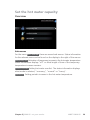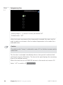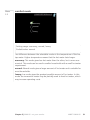
1
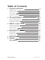
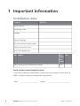
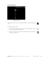
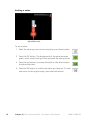
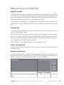
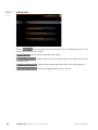
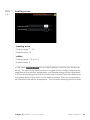
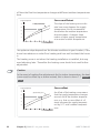
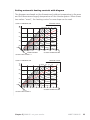
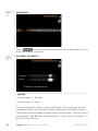
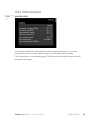
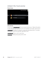
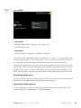
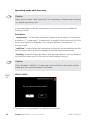
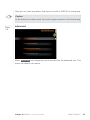
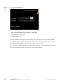
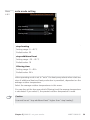
User manual
LEK
NIBE™ SMO 05
Accessories
LEK
UHB GB 1146-1
431198
4XLFN JXLGH
1DYLJDWLRQ
2N EXWWRQ FRQILUPVHOHFW
8SGRZQ EXWWRQV
PRYHLQFUHDVHUHGXFH
%DFN EXWWRQ EDFNXQGRH[LW
A detailed explanation of the button functions can be found on page 10.
How to scroll through menus and make different settings is described on
page 12.
6HW WKH LQGRRU FOLPDWH
LQGRRU FOLPDWH
KRW ZDWHU
LQIR
P\ V\VWHP
;
The mode for setting the indoor temperature is reached, when in the start
mode in the main menu, by pressing the OK button twice. Read more
about the settings on page 18.
,QFUHDVH KRW ZDWHU YROXPH
7(0325$5< /8; RII
;
;
To temporarily increase the amount of hot water (if a hot water heater is
installed to your SMO 05), first push the down button once to mark menu
2 (water droplet) and then press the OK button twice. Read more about
the settings on page 30.
In event of disturbances in comfort
If a disturbance in comfort of any type occurs there are some measures
that can be taken before you need to contact your installer. See page 43
for instructions.
Table of Contents
1 Important information
2
Installation data
Safety information
Serial number
Contact information
SMO 05 – An excellent choice
2
3
4
5
7
2 The control module – the heart of the house
Control module's function
Contact with SMO 05
Maintenance of SMO 05
3 SMO 05 – at your service
Set the indoor climate
Set the hot water capacity
Get information
Adjust the heat pump
4 Disturbances in comfort
8
8
9
15
17
17
29
33
34
42
Manage alarm
Troubleshooting
Add. heat only
42
43
45
5 Technical data
6 Glossary
46
47
Item register
Table of Contents |
51
NIBE™ SMO 05
1
1 Important information
Installation data
Product
SMO 05
Serial number
Installation date
Installer
Type of docking
Accumulator/hot water heater
Heat pump/output size
Add. heat type/power
No. Name
DeSet
fault
settings
1.9.1 heating curve (offset/curve slope)
0/7
Serial number must always be given
Certification that the installation is carried out according to instructions in
NIBE's installer manual and applicable regulations.
Date
2
__________________
Chapter 1 | Important information
Signed
_________________________
NIBE™ SMO 05
Safety information
This appliance is not intended for use by persons (including children) with
reduced physical, sensory or mental capabilities, or lack of experience and
knowledge, unless they have been given supervision or instruction concerning
use of the appliance by a person responsible for their safety.
Children should be supervised to ensure that they do not play with the appliance.
Rights to make any design or technical modifications are reserved.
©NIBE 2011.
Symbols
NOTE
This symbol indicates danger to machine or person.
Caution
This symbol indicates important information about what you should observe
when maintaining your installation.
TIP
This symbol indicates tips on how to facilitate using the product.
Marking
This accessory is CE marked and fulfils IP20 (room unit) and IP21 (unit box).
The CE marking means that NIBE ensures that the product meets all regulations that are placed on it based on relevant EU directives. The CE mark is
obligatory for most products sold in the EU, regardless where they are made.
IP20 means that the product can be touched by hand, that objects with a
diameter larger than or equivalent to12.5 mm cannot penetrate and cause
damage.
Chapter 1 | Important information
NIBE™ SMO 05
3
Serial number
The serial number can be found on one long side of the cover on the unit
box.
LEK
6HULDO QXPEHU
Caution
Always give the product's serial number when reporting a fault.
4
Chapter 1 | Important information
NIBE™ SMO 05
Contact information
AT KNV Energietechnik GmbH, Gahberggasse 11, 4861 Schörfling
Tel: +43 (0)7662 8963-0 Fax: +43 (0)7662 8963-44 E-mail: [email protected]
www.knv.at
CH NIBE Wärmetechnik AG, Winterthurerstrasse 710, CH-8247 Flurlingen
Tel: (52) 647 00 30 Fax: (52) 647 00 31 E-mail: [email protected] www.nibe.ch
CZ Druzstevni zavody Drazice s.r.o, Drazice 69, CZ - 294 71 Benatky nad
Jizerou
Tel: +420 326 373 801 Fax: +420 326 373 803 E-mail: [email protected]
www.nibe.cz
DE NIBE Systemtechnik GmbH, Am Reiherpfahl 3, 29223 Celle
Tel: 05141/7546-0 Fax: 05141/7546-99 E-mail: [email protected] www.nibe.de
DK Vølund Varmeteknik A/S, Member of the Nibe Group, Brogårdsvej 7,
6920 Videbæk
Tel: 97 17 20 33 Fax: 97 17 29 33 E-mail: [email protected] www.volundvt.dk
FI NIBE Energy Systems OY, Juurakkotie 3, 01510 Vantaa
Puh: 09-274 697 0 Fax: 09-274 697 40 E-mail: [email protected] www.nibe.fi
GB NIBE Energy Systems Ltd, 3C Broom Business Park, Bridge Way,
Chesterfield S41 9QG
Tel: 0845 095 1200 Fax: 0845 095 1201 E-mail: [email protected]
www.nibe.co.uk
NL NIBE Energietechniek B.V., Postbus 2, NL-4797 ZG WILLEMSTAD (NB)
Tel: 0168 477722 Fax: 0168 476998 E-mail: [email protected] www.nibenl.nl
NO ABK AS, Brobekkveien 80, 0582 Oslo, Postadresse: Postboks 64 Vollebekk,
0516 Oslo
Tel. sentralbord: +47 02320 E-mail: [email protected] www.nibeenergysystems.no
PL NIBE-BIAWAR Sp. z o. o. Aleja Jana Pawła II 57, 15-703 BIAŁYSTOK
Tel: 085 662 84 90 Fax: 085 662 84 14 E-mail: [email protected]
www.biawar.com.pl
RU © "EVAN" 17, per. Boynovskiy, Nizhny Novgorod
Tel./fax +7 831 419 57 06 E-mail: [email protected] www.nibe-evan.ru
SE NIBE AB Sweden, Box 14, Hannabadsvägen 5, SE-285 21 Markaryd
Tel: +46-(0)433-73 000 Fax: +46-(0)433-73 190 E-mail: [email protected]
www.nibe.se
Chapter 1 | Important information
NIBE™ SMO 05
5
For countries not mention in this list, please contact Nibe Sweden or check www.nibe.eu
for more information.
6
Chapter 1 | Important information
NIBE™ SMO 05
SMO 05 – An excellent choice
SMO 05 is a control module, which has been introduced to supply your home
with inexpensive and environmentally friendly heating. Heat production is
reliable and economical with a NIBE air/water heat pump and accumulator/water heater.
An additional heater (for example electric/oil/gas boiler) can engage automatically if something unexpected should occur or as reserve operation.
Excellent properties for SMO 05:
႑
Easy to read display
The room unit has an easy to read display with easy-to-understand menus
that facilitate setting a comfortable indoor climate.
႑
Easy to install
SMO 05 is easy to install together with NIBE
F2015/F2025/F2016/F2026/F2300. When installing together with these,
the control module is connected to the heat pump, which enables you to
see any heat pump alarms in SMO 05.
႑
Two part design
SMO 05 consists of a room unit and a unit box. The room unit can be
positioned in a convenient place for the user and the unit box can be
positioned in another location together with other equipment in your
system.
Chapter 1 | Important information
NIBE™ SMO 05
7
2 The control module – the heart
of the house
Control module's function
SMO 05 is a simple control module, which, together with NIBE air/water heat
pump, accumulator/water heater and additional heater (e.g. electric/oil/gas
boiler), creates a complete installation.
8
Chapter 2 | The control module – the heart of the house
NIBE™ SMO 05
Contact with SMO 05
Room unit
$
% & ' (
There is a room unit for SMO 05 that is used to control your installation. Here
you:
႑
sets the indoor climate and hot water as well as adjusts the heat pump
to your needs.
႑
receive information about settings, status and events.
႑
see different types of alarms and receive instructions about how they are
to be rectified.
A
Display
B
Stand-by button
C
Back button
Instructions, settings and operational information are shown on the
display.
The room unit can be switched to stand-by mode using the stand-by
button. Heat pump operation is not affected by pressing the button.
The back button is used to:
႑ go back to the previous menu.
႑ change a setting that has not been confirmed.
Chapter 2 | The control module – the heart of the house
NIBE™ SMO 05
9
D
OK button
E
Up and down buttons
The OK button is used to:
႑ confirm selections of sub menus/options/set values.
With the up and down buttons you can:
႑ scroll in menus and between options.
႑ increase and decrease the values.
႑ change page in multiple page instructions
Menu system
When the room unit starts up you come to the information menu. Basic information about your system status is shown here.
2XWGRRU WHPSHUDWXUH
7HPS OX[ DFWLYDWHG
,QGRRU WHPSHUDWXUH
+RW ZDWHU WHPS
Press any button to go to the main menu.
10
Chapter 2 | The control module – the heart of the house
NIBE™ SMO 05
LQGRRU FOLPDWH
KRW ZDWHU
LQIR
P\ V\VWHP
,QGRRU WHPSHUDWXUH
LI URRP VHQVRUV DUH
LQVWDOOHG
+RW ZDWHU WHPS
,QIRUPDWLRQ DERXW
RSHUDWLRQ
,QIRUPDWLRQ DERXW WKH
KHDWLQJ V\VWHP
The information menu shows:
႑
on starting
႑
when the back button in the main menu is pressed
႑
after 15 minutes of inactivity.
In the event of an alarm a symbol is shown in the display together with the
alarm's number. See page 43 for instructions.
In the other menus the alarm symbol is shown in the bottom right hand
corner.
Chapter 2 | The control module – the heart of the house
NIBE™ SMO 05
11
Menu 1
INDOOR CLIMATE
Setting the indoor climate. See page 17.
Menu 2
HOT WATER
Setting the hot water production. See page 29.
This menu only appears if a water heater is activated in the menu system.
Menu 3
INFO
Display of temperature and other operating information. See page 33.
Menu 4
MY INSTALLATION
Setting operating mode etc. See page 34.
Operation
To move the cursor, press the up or down button. The marked position is
brighter and/or has a turned up tab.
Selecting menu
To advance in the menu system select a sub-menu by marking it by using the
up and down buttons and then pressing the OK button.
12
Chapter 2 | The control module – the heart of the house
NIBE™ SMO 05
Selecting options
7(0325$5< /8; RII
6HOHFWDEOH RSWLRQV
In an options menu the current selected option is indicated by a green
tick.
To select another option:
1. Mark the applicable option using the up or down button. One of
the options is pre-selected (white).
2. Press the OK button to confirm the selected option. The selected
option has a green tick.
Chapter 2 | The control module – the heart of the house
NIBE™ SMO 05
13
Setting a value
7(03(5$785( $GMXVWDEOH YDOXH
To set a value:
1. Mark the value you want to set using the up or down button.
2. Press the OK button. The background of the value becomes
green, which means that you have accessed the setting mode.
3. Press the up button to increase the value or the down button
to reduce the value.
4. Press the OK button to confirm the value you have set. To undo
and return to the original value, press the back button.
14
Chapter 2 | The control module – the heart of the house
NIBE™ SMO 05
Maintenance of SMO 05
Regular checks
Your heat pump requires minimal maintenance after commissioning. On the
other hand, it is recommended that you check your installation regularly. For
more information regarding the maintenance of heat pumps and/or accumulator tanks/water heaters, refer to the relevant manual.
If something unusual occurs, messages about the malfunction appear in the
display in the form of different alarm texts. See alarm management on page
42.
Saving tips
Your heat pump installation produces heat and hot water. This occurs via the
control settings you made.
Factors that affect the energy consumption are, for example, indoor temperature, hot water consumption, the insulation level of the house and whether
the house has many large window surfaces. The position of the house, e.g.
wind exposure is also an affecting factor.
If you activate "Hot water Economy", less energy is used.
Power consumption
Increasing the indoor temperature one degree increases power consumption
by approx. 5%.
Domestic electricity
In the past it has been calculated that an average Swedish household has an
approximate annual consumption of 5000 kWh domestic electricity/year. In
today's society it is usually between 6000-12.000 kWh/year.
Equipment
Flat-screen (Operation: 5 h/day, Standby: 19
h/day)
Normal Output (W) Approximate
annual
consumption
(kWh)
Operation Standby
200
2
Chapter 2 | The control module – the heart of the house
380
NIBE™ SMO 05
15
Equipment
Digital box (Operation: 5 h/day, Standby: 19
h/day)
DVD (Operation: 2 h/week)
TV games console (Operation: 6 h/week)
Radio/stereo (Operation: 3 h/day)
Computer incl. screen (Operation: 3 h/day,
standby 21 h/day)
Bulb (Operation 8 h/day)
Spot light, Halogen (Operation 8 h/day)
Cooler (Operation: 24 h/day)
Freezer (Operation: 24 h/day)
Oven, hob (Operation: 40 min/day)
Oven (Operation: 2 h/week)
Dishwasher, cold water connection (Operation
1 time/day)
Washing machine (Operation: 1 time/day)
Tumble drier (Operation: 1 time/day)
Vacuum cleaner (Operation: 2 h/week)
Engine block heater (Operation: 1 h/day, 4
months a year)
Passenger compartment heater (Operation: 1
h/day, 4 months a year)
Normal Output (W) Approximate
annual
consumption
(kWh)
11
10
90
15
160
40
100
5
2
1
2
45
67
50
120
60
20
100
120
1500
3000
2000
-
175
55
165
380
365
310
730
2000
2000
1000
400
-
730
730
100
50
800
-
100
These values are approximate example values.
Example: A family with 2 children live in a house with 1 flat-screen TV, 1 digital box, 1 DVD player, 1 TV games console, 2 computers, 3 stereos, 2 bulbs
in the WC, 2 bulbs in the bathroom, 4 bulbs in the kitchen, 3 bulbs outside,
a washing machine, tumble drier, fridge, freezer, oven, vacuum cleaner, engine block heater = 6240 kWh domestic electricity/year.
Energy meter
Check the accommodation's energy meter regularly, preferably once a month.
This will indicate any changes in power consumption.
16
Chapter 2 | The control module – the heart of the house
NIBE™ SMO 05
3 SMO 05 – at your service
Set the indoor climate
Overview
,1'225 &/,0$7( WHPSHUDWXUH
DGYDQFHG
Sub-menus
For the menu INDOOR CLIMATE there are several sub-menus. Status information for the relevant menu can be found on the display to the right of the
menus.
temperature Setting the temperature for the climate system. The status information shows the set values for the climate system.
advanced Setting of heat curve, adjusting with external contact, minimum
value for supply temperature and room sensor.
Chapter 3 | SMO 05 – at your service
NIBE™ SMO 05
17
Menu
1.1
temperature
7(03(5$785( Set the temperature (with room sensors installed and activated):
Setting range: 5 - 30 °C
Default value: 20
The value in the display appears as a temperature in °C if the heating system
is controlled by a room sensor.
To change the room temperature, use the up and down buttons to set the
desired temperature in the display. Confirm the new setting by pressing the
OK button. The new temperature is shown on the right-hand side of the
symbol in the display.
Setting the temperature (without room sensors activated):
Setting range: -10 to +10
Default value: 0
The display shows the set values for heating (curve offset). To increase or reduce the indoor temperature, increase or reduce the value on the display.
Use the up and down buttons to set a new value. Confirm the new setting
by pressing the OK button.
The number of steps the value has to be changed to achieve a degree change
of the indoor temperature depends on the heating unit. One step for under
floor heating whilst radiators may require three.
18
Chapter 3 | SMO 05 – at your service
NIBE™ SMO 05
Setting the desired value. The new value is shown on the right-hand side of
the symbol in the display.
Caution
An increase in the room temperature can be slowed by the thermostats for
the radiators or under floor heating. Therefore, open the thermostat valves
fully, except in those rooms where a cooler temperature is required, e.g.
bedrooms.
TIP
Wait 24 hours before making a new setting, so that the room temperature
has time to stabilise.
If it is cold outdoors and the room temperature is too low, increase the curve
slope in menu 1.9.1 by one increment.
If it is cold outdoors and the room temperature is too high, lower the curve
slope menu 1.9.1 by one increment.
If it is warm outdoors and the room temperature is too low, increase the
value in menu 1.1 by one increment.
If it is warm outdoors and the room temperature is too high, reduce the
value in menu 1.1 by one increment.
Chapter 3 | SMO 05 – at your service
NIBE™ SMO 05
19
Menu
1.9
advanced
$'9$1&(' KHDWLQJ FXUYH
H[WHUQDO DGMXVWPHQW
PLQ VXSSO\ WHPSHUDWXUH
URRP VHQVRU VHWWLQJV
Menu advanced has orange text and is intended for the advanced user. This
menu has several sub-menus.
heating curve Setting the heating curve slope.
external adjustment Setting the heat curve offset when the external contact
is connected.
min. flow line temp. Setting minimum permitted flow line temperature.
room sensor settings Settings regarding the room sensor.
20
Chapter 3 | SMO 05 – at your service
NIBE™ SMO 05
Menu
1.9.1
heating curve
+($7,1* &859( KHDWLQJ FXUYH
FXUYH RIIVHW
heating curve
Setting range: 1 - 15
Default value: 13
offset
Setting range: -10 to +10
Default value: 0
In the menu heating curve the so-called heating curve for your house can
be set. The task of the heating curve is to give an even indoor temperature,
regardless of the outdoor temperature, and thereby energy efficient operation.
It is from this heating curve that the heat pump’s control computer determines
the temperature of the water to the heating system, flow line temperature,
and therefore the indoor temperature. You can select heating curve and read
Chapter 3 | SMO 05 – at your service
NIBE™ SMO 05
21
off how the flow line temperature changes at different outdoor temperatures
here.
Curve coefficient
6XSSO\ WHPSHUDWXUH
°C
70
The slope of the heating curve indicates how many degrees the supply
temperature is to be increased/reduced when the outdoor temperature
drops/increases. A steeper slope
means a higher supply temperature
at a certain outdoor temperature.
6WHHSHU
FXUYH VORSH
Brantare
kurvlutning
60
50
40
30
10
0
- 10
- 20
- 30
- 40°C
UTETEMPERATUR
2XWGRRU
WHPSHUDWXUH
The optimum slope depends on the climate conditions in your location, if the
house has radiators or under floor heating and how well insulated the house
is.
The heating curve is set when the heating installation is installed, but may
need adjusting later. Thereafter the heating curve should not need further
adjustment.
Caution
In the event of making fine adjustments for the indoor temperature, the heat
curve must be offset up or down instead, this is done in menu 1.1 temperature .
Curve offset
6XSSO\ WHPSHUDWXUH
°C
70
An offset of the heating curve means
that the supply temperature changes
as much for all the outdoor temperatures, e.g. that a curve offset of +2
steps increases the supply temperature by 5 °C at all outdoor temperatures.
2IIVHW KHDWLQJ
FXUYH
Förskjuten
värmekurva
60
50
40
30
10
0
- 10
- 20
- 30
- 40°C
UTETEMPERATUR
2XWGRRU
WHPSHUDWXUH
22
Chapter 3 | SMO 05 – at your service
NIBE™ SMO 05
Setting automatic heating controls with diagram
The diagrams are based on the dimensioned outdoor temperature in the area
and the dimensioned supply temperature of the climate system. When these
two values "meet", the heating control's curve slope can be read.
FRAMLEDNINGSTEMPERATUR
6833/< 7(03(5$785(
+($7,1* &859(
VÄRMEKURVA
15 14 13 12
70
11
9
8
60
7
6
50
5
40
4
3
30
2
+5
1
10
0
- 10
- 20
- 40
- 30
2876,'(
7(03(5$785(
UTETEMPERATUR
-5
FÖRSKJUTNING
VÄRMEKURVA
(-2)
2))6(7 +($7 &859(
bbb
+($7,1* &859(
VÄRMEKURVA
6833/< 7(03(5$785(
FRAMLEDNINGSTEMPERATUR
10
15 14 13 12
70
11
10
9
8
60
7
6
50
5
4
40
3
2
30
1
+5
10
0
- 10
-5
FÖRSKJUTNING
VÄRMEKURVA
(0)
2))6(7 +($7 &859(
bbb
- 20
- 30
- 40
2876,'(
7(03(5$785(
UTETEMPERATUR
Chapter 3 | SMO 05 – at your service
NIBE™ SMO 05
23
+($7,1* &859(
VÄRMEKURVA
FRAMLEDNINGSTEMPERATUR
6833/< 7(03(5$785(
15 14 13 12 11
70
10
9
8
7
60
6
5
50
4
3
40
2
30
1
+5
10
- 10
0
- 20
°C
70
Because the flow line temperature
cannot be calculated higher than the
set maximum value or lower than the
set minimum value the heating curve
flattens out at these temperatures.
0D[LPXP
YDOXH
Maximivärde
50
40
30
0LQLPXP
YDOXH
Minimivärde
10
- 40
Flow line temperature– maximum and minimum values
6XSSO\ WHPSHUDWXUH
60
- 30
2876,'(
7(03(5$785(
UTETEMPERATUR
-5
FÖRSKJUTNING
VÄRMEKURVA
(+2)
2))6(7 +($7 &859(
bbb
0
- 10
- 20
- 30
- 40°C
UTETEMPERATUR
2XWGRRU
WHPSHUDWXUH
Caution
Underfloor heating systems are normally max flow line temperature set
between 35 and 45 °C.
Check the max temperature for your floor with your installer/floor supplier.
Use the up and down buttons to set a new value. Confirm the new setting
by pressing the OK button.
To select another heat curve (slope):
1. Press the OK button to access the setting mode
24
Chapter 3 | SMO 05 – at your service
NIBE™ SMO 05
2. Select a new heating curve. The heating curves are numbered from 1 to
15, the greater the number, the steeper the slope and the greater the
supply temperature.
3. Press the OK button to exit the setting.
TIP
Wait 24 hours before making a new setting, so that the room temperature
has time to stabilise.
If it is cold outdoors and the room temperature is too low, increase the curve
slope by one increment.
If it is cold outdoors and the room temperature is too high, lower the curve
slope by one increment.
If it is warm outdoors and the room temperature is too low, increase the
curve offset by one increment.
If it is warm outdoors and the room temperature is too high, lower the curve
offset by one increment.
Chapter 3 | SMO 05 – at your service
NIBE™ SMO 05
25
Menu
1.9.2
external adjustment
(;7(51$/ $'-8670(17 FOLPDWH V\VWHP climate system (with room temperature sensors installed and
activated)
Setting range: 5 - 30 °C
Default value: 20
climate system (without room temperature sensors activated)
Setting range: -10 to +10
Default value: 0
Connecting an external contact, for example, a room thermostat or a timer
allows you to temporarily or periodically raise or lower the room temperature.
When the contact is on, the heat curve offset is changed by the number of
steps selected in the menu. If a room sensor is installed and activated the
desired room temperature (°C) is set.
26
Chapter 3 | SMO 05 – at your service
NIBE™ SMO 05
Menu
1.9.3
min. flow line temp.
0,1 6833/< 7(03 FOLPDWH V\VWHP climate system
Setting range: 15 – 50 °C
Default value: 15 °C
Set the minimum temperature on the supply temperature to the climate system. This means that SMO 05 never calculates a temperature lower than that
set here.
TIP
The value can be increased if you have, for example, a cellar that you always
want to heat, even in summer.
You may also need to increase the value in "stop heating" menu 4.9.2 "auto
mode setting".
Chapter 3 | SMO 05 – at your service
NIBE™ SMO 05
27
Menu
1.9.4
room sensor settings
5220 6(1625 6(77,1*6 FRQWURO URRP VHQVRU V\VWHP IDFWRU V\VWHP factor system
Setting range: 0.1 - 6.0
Default value: 2.0
Room sensors to control the room temperature can be activated here.
Here you can set a factor that determines how much the supply temperature
is to be affected by the difference between the desired room temperature
and the actual room temperature. A higher value gives a greater change of
the heating curve's set offset.
28
Chapter 3 | SMO 05 – at your service
NIBE™ SMO 05
Set the hot water capacity
Overview
+27 :$7(5 WHPSRUDU\ OX[
FRPIRUW PRGH
DGYDQFHG
Sub-menus
For the menu HOT WATER there are several sub-menus. Status information
for the relevant menu can be found on the display to the right of the menus.
temporary lux Activation of temporary increase in the hot water temperature.
Status information displays “off" or what length of time of the temporary
temperature increase remains.
comfort mode Setting hot water comfort. The status information displays
what mode is selected, "economy", "normal" or "luxury".
advanced Setting periodic increase in the hot water temperature.
Chapter 3 | SMO 05 – at your service
NIBE™ SMO 05
29
Menu
2.1
temporary lux
7(0325$5< /8; RII
Setting range: 1, 3, 6 and 12 hours, and mode"off"
Default value: "off"
When hot water requirement has temporarily increased this menu can be
used to select an increase in the hot water temperature to lux mode for a
selectable time.
Caution
If comfort mode "luxury" is selected in menu 2.2 no further increase can be
carried out.
The function is activated immediately when a time period is selected and
confirmed using the OK button. The time to the right displays the remaining
time at the selected setting.
When the time has run out SMO 05 returns to the mode set in menu 2.2.
Select “off" to switch off temporary lux .
30
Chapter 3 | SMO 05 – at your service
NIBE™ SMO 05
Menu
2.2
comfort mode
&20)257 02'( HFRQRP\
QRUPDO
OX[XU\
Setting range: economy, normal, luxury
Default value: normal
The difference between the selectable modes is the temperature of the hot
tap water. Higher temperature means that the hot water lasts longer.
economy: This mode gives less hot water than the other, but is more economical. This mode can be used in smaller households with a small hot water
requirement.
normal: Normal mode gives a larger amount of hot water and is suitable for
most households.
luxury: Lux mode gives the greatest possible amount of hot water. In this
mode the immersion heater may be partially used to heat hot water, which
may increase operating costs.
Chapter 3 | SMO 05 – at your service
NIBE™ SMO 05
31
Menu
2.9
advanced
$'9$1&(' SHULRGLF LQFUHDVHV
Menu advanced has orange text and is intended for the advanced user. This
menu has several sub-menus.
Menu
2.9.1
periodic increases
3(5,2',& ,1&5($6(6 DFWLYDWHG
SHULRG
GD\V WR QH[W SHULRGLF LQF
period
Setting range: 1 - 90 days
Default value: 14 days
To prevent bacterial growth in the water heater, the compressor and the
immersion heater can increase hot water temperature at regular intervals.
The length of time between increases can be selected here. The time can be
set between 1 and 90 days. Factory setting is 14 days. Untick "activated" to
switch off the function.
32
Chapter 3 | SMO 05 – at your service
NIBE™ SMO 05
Get information
Menu
3.1
service info
,1)2 KRW ZDWHU FKDUJLQJ %7
KRW ZDWHU WRS %7
FDOFXODWHG IORZ WHPS
RXWGRRU WHPS %7
DYJ RXWGRRU WHPS
RS SULRULWLVDWLRQ
URRP WHPSHUDWXUH %7
KRW ZDWHU
Information about the heat pump’s actual operating status (e.g. current
temperatures etc.) can be obtained here. No changes can be made.
The information is on several pages. Push the up and down buttons to scroll
between the pages.
Chapter 3 | SMO 05 – at your service
NIBE™ SMO 05
33
Adjust the heat pump
Overview
0< 6<67(0 RS PRGH
DGYDQFHG
Sub-menus
For the menu HEAT PUMP there are several sub-menus. Status information
for the relevant menu can be found on the display to the right of the menus.
op. mode Activation of manual or automatic operating mode. The status
information shows the selected operating mode.
alarm reset Alarms can be reset here.
advanced Setting heat pump work mode.
34
Chapter 3 | SMO 05 – at your service
NIBE™ SMO 05
Menu
4.2
op. mode
23 02'( DXWR
KHDWLQJ
PDQXDO
DGG KHDW RQO\
DGGLWLRQ
op. mode
Setting range: auto, manual, add. heat only
Default value: auto
functions
Setting range: compressor, addition, heating
The heat pump operating mode is usually set to "auto". It is also possible to
set the heat pump to "add. heat only", but only when an addition is used,
or "manual" and select yourself what functions are to be permitted.
Change the operating mode by marking the desired mode and pressing the
OK button. When an operating mode is selected, selectable options are displayed to the right. To select selectable functions that are permitted or not,
mark the function using the up and down buttons and press the OK button.
Operating mode auto
In this operating mode you cannot select which functions are to be permitted
because it is handled automatically by the heat pump.
Operating mode manual
In this operating mode you can select what functions are permitted. You
cannot deselect "compressor" in manual mode.
Chapter 3 | SMO 05 – at your service
NIBE™ SMO 05
35
Operating mode add. heat only
Caution
If you choose mode "add. heat only" the compressor is deselected and there
is a higher operating cost.
In this operating mode the compressor is not active and only additional
heating is used.
Functions
"compressor" is that which produces heating and hot water for the accommodation. If "compressor" is deselected, a symbol in the main menu on the
heat pump symbol is displayed. You cannot deselect "compressor" in
manual mode.
"addition" is what helps the compressor to heat the accommodation and/or
the hot water when it cannot manage the whole requirement alone.
"heating" means that you get heat in the accommodation. You can deselect
the function when you do not wish to have heating running.
Caution
If you deselect "addition" it may mean that insufficient hot water and/or
heating in the accommodation is achieved.
Menu
4.8
alarm reset
$/$50 5(6(7 'R \RX ZDQW WR UHVHW WKH DODUP"
QR
\HV
This menu is only available if an alarm has occurred.
36
Chapter 3 | SMO 05 – at your service
NIBE™ SMO 05
Here you can reset any alarms that have occurred in SMO 05 or heat pump.
Caution
In the event of an alarm reset, the control system restarts in the heat pump.
Menu
4.9
advanced
$'9$1&(' RS SULRULWLVDWLRQ
DXWR PRGH VHWWLQJ
GHJUHH PLQXWH VHWWLQJ
IDFWRU\ VHWWLQJ XVHU
Menu advanced has orange text and is intended for the advanced user. This
menu has several sub-menus.
Chapter 3 | SMO 05 – at your service
NIBE™ SMO 05
37
Menu
4.9.1
op. prioritisation
23 35,25,6$7,21 KRW ZDWHU
PLQ
KHDWLQJ
PLQ
DFWLYH KRW ZDWHU
op. prioritisation hot water / heating
Setting range: 0 to 180
Default value: 20
Choose here how long the heat pump should work with each requirement
if there are two requirements at the same time. If there is only one requirement the heat pump only works with that requirement.
If 0 minutes is selected it means that requirement is not prioritised, but will
only be activated when there is no other requirement.
38
Chapter 3 | SMO 05 – at your service
NIBE™ SMO 05
Menu
4.9.2
auto mode setting
$872 02'( 6(77,1* VWRS KHDWLQJ
VWRS DGGLWLRQDO KHDW
ILOWHULQJ WLPH
KUV
stop heating
Setting range: 0 – 40 °C
Default value: 20
stop additional heat
Setting range: -20 – 40 °C
Default value: 15
filtering time
Setting range: 0 – 48 h
Default value: 24 h
When operating mode is set to "auto“ the heat pump selects when start and
stop of additional heat and heat production is permitted, dependent on the
average outdoor temperature.
Select the average outdoor temperatures in this menu.
You can also set the time over which (filtering time) the average temperature
is calculated. If you select 0, the present outdoor temperature is used.
Caution
It cannot be set "stop additional heat" higher than "stop heating".
Chapter 3 | SMO 05 – at your service
NIBE™ SMO 05
39
Menu
4.9.3
degree minute setting
'(*5(( 0,187( 6(77,1* FXUUHQW YDOXH
'0
VWDUW FRPSUHVVRU
'0
VWDUW DGGLWLRQ
'0
VWRS DGGLWLRQDO KHDW
'0
current value
Setting range: -3000 – 100
start compressor
Setting range: -1000 – -30
Default value: -60
start addition
Setting range: -2000 – -30
Default value: -400
stop additional heat
Setting range: -2000 – -30
Default value: -230
Degree minutes are a measurement of the current heating requirement in
the house and determine when the compressor respectively additional heat
will start/stop.
Caution
Higher value on "start compressor" gives more compressor starts, which increases wear in the compressor. Too low value can give uneven indoor
temperatures.
40
Chapter 3 | SMO 05 – at your service
NIBE™ SMO 05
Menu
4.9.4
factory setting user
)$&725< 6(77,1* 86(5 'R \RX ZDQW WR UHVHW DOO XVHU
VHWWLQJV WR IDFWRU\ GHIDXOW"
QR
\HV
All settings that are available to the user (including advanced menus) can be
reset to default values here.
Caution
After factory setting, personal settings such as heating curves must be reset.
Chapter 3 | SMO 05 – at your service
NIBE™ SMO 05
41
4 Disturbances in comfort
In most cases, the heat pump notes malfunctions and indicates this with
alarms and shows instructions in the room unit display. See page 42 for information about managing alarms. If the malfunction does not appear in the
display, or if the display is not lit, the following troubleshooting guide can be
used.
Manage alarm
$ODUP (%
+LJK SUHVVXUH DODUP
In the event of an alarm, a malfunction has occurred, which is indicated by
an alarm clock in the room unit.
Alarm
In the event of an alarm a malfunction has occurred that SMO 05 cannot
rectify itself. The display shows what type of alarm it is.
If the alarm does not reset, contact your installer for suitable remedial action.
NOTE
Always give the heat pump, control module and any accumulator tank serial
numbers when contacting your installer.
Alarm list
Alarm AA25:## (where ## is a number) means that the alarm has occurred
in SMO 05.
42
Chapter 4 | Disturbances in comfort
NIBE™ SMO 05
Alarm EB100:## (where ## is a number) means that the alarm has occurred
in the heat pump (see the heat pump manual).
Sensor alarm BT1/BT6/BT25:
The sensor is probably broken or has lost contact with the accessory card.
The alarm resets automatically after correct connection.
႑
Contact your installer!
Communication alarm heat pump
The heat pump has lost contact with the accessory card.
႑
Contact your installer!
Communication alarm accessory card
The room unit has lost contact with the accessory card.
႑
Contact your installer!
Resetting the alarm
Alarm reset can be carried out in two ways.
1. Select "yes" in menu 4.8.
2. Restart of SMO 05 (on/off of voltage to SMO 05).
In the event of an alarm reset, the control system restarts in the heat pump
and any alarms in SMO 05 are reset.
NOTE
Contact your installer if the alarm recurs.
Troubleshooting
If the malfunction is not shown in the display the following tips can be used
or consult the heat pump manual.
Basic actions
Start by checking the following possible fault sources:
႑
That the heat pump is running or that the supply cable to SMO 05 is
connected.
႑
Group and main fuses of the accommodation.
႑
The property's earth circuit breaker.
Chapter 4 | Disturbances in comfort
NIBE™ SMO 05
43
Low hot water temperature or a lack of hot water
This part of the fault-tracing chapter only applies if the heat pump is docked
to the hot water heater.
႑
Heat pump in incorrect operating mode.
႑ If mode "manual" is selected, select "addition".
႑
Large hot water consumption.
႑ Wait until the hot water has heated up. Temporarily increased hot
water capacity (temporary lux) can be activated in menu 2.1.
႑
Too low hot water setting.
႑ Enter menu 2.2 and select a higher comfort mode.
႑
Too low or no operating prioritisation of hot water.
႑ Enter menu 4.9.1 and increase the time for when hot water is to be
prioritised.
Low room temperature
႑
Closed thermostats in several rooms.
႑ Set the thermostats to max in as many rooms as possible. Adjust the
room temperature via menu 1.1 instead of choking the thermostats.
႑
Installation in incorrect operating mode.
႑ Enter menu 4.2. If mode "auto" is selected, select a higher value on
"stop heating“ in menu 4.9.2.
႑ If mode "manual" is selected, select "heating". If this is not enough,
select "addition".
႑
Too low set value on the automatic heating control.
႑ Enter menu 1.1 (temperature) and adjust the heat curve offset of the
heat curve. If the room temperature is only low in cold weather the
curve slope in the menu 1.9.1 (heating curve) needs to be adjusted
up.
႑
Too low or no operating prioritisation of heat.
႑ Enter menu 4.9.1 and increase the time for when heating is to be
prioritised.
႑
External switch for changing the room heating activated.
႑ Check any external switches.
44
Chapter 4 | Disturbances in comfort
NIBE™ SMO 05
High room temperature
႑
Too high set value on the automatic heating control.
႑ Enter menu 1.1 (temperature) and adjust the heat curve offset
downwards. If the room temperature is only high in cold weather the
curve slope in menu 1.9.1 (heating curve) needs to be adjusted down.
႑
External switch for changing the room heating activated.
႑ Check any external switches.
Add. heat only
If you are unsuccessful in rectifying the fault and are unable to heat the house,
you can, whilst waiting for assistance, continue running SMO 05 in ”add.
heat only”. This means that SMO 05 only uses the additional heating to heat
the house and domestic hot water.
Set SMO 05 to additional heat mode
1. Go to menu 4.2 op. mode.
2. Mark ”add. heat only” using the control buttons and then press the OK
button.
3. Return to the main menus by pressing the Back button.
Chapter 4 | Disturbances in comfort
NIBE™ SMO 05
45
5 Technical data
Detailed technical specifications for this product can be found in the installation manual (www.nibe.eu).
46
Chapter 5 | Technical data
NIBE™ SMO 05
6 Glossary
Additional heat:
The additional heat is the heat produced in addition to the heat supplied by
the compressor in your heat pump. Additional heaters can be for example,
immersion heater, electric heater, solar power system, gas/oil/pellet/wood
burner or district heating.
Calculated flow line temperature
The temperature that the heat pump calculates that the heating system requires for an optimum accommodation temperature. The colder the outdoor
temperature, the higher the calculated supply temperature.
Circulation pump
Pump that circulates liquid in a pipe system.
Climate system
Climate systems can also be called heating systems. The building is heated
using radiators, under floor coils or convector fans.
Compressor
Compresses the gas state refrigerant. When the refrigerant is compressed,
the pressure and the temperature increase.
Condenser
Heat exchanger where the hot gas state refrigerant condenses (cooled and
becomes a liquid) and releases heat energy to the house heating and hot
water systems.
COP
If it is stated that a heat pump has COP 4, this means, in principle that if you
insert 10 pence, you will get 40 pence worth of heat. It is the efficiency of
the heat pump. This is measured at different measurement values, e.g.: 7/45
where 7 stands for the outdoor temperature and 45 for how many degrees
the supply temperature is.
Chapter 6 | Glossary
NIBE™ SMO 05
47
Disturbances in comfort
Disturbances in comfort are undesirable changes to the hot water/indoor
comfort, for example when the temperature of the hot water is too low or
if the indoor temperature is not at the desired level.
A malfunction in the heat pump can sometimes be noticed in the form of a
disturbance in comfort.
In most cases, the heat pump notes operational interference and indicates
this with alarms and shows instructions in the display.
Domestic hot water
The water one showers in for example.
DUT, dimensioned outdoor temperature
The dimensioned outdoor temperature differs depending on where you live.
The lower the dimensioned outdoor temperature, the lower the value should
be selected on "selecting a heat curve".
Efficiency
A measurement of how effective the heat pump is. The higher the value is
the better it is.
Electrical addition
This is electricity that, for example, an immersion heater uses as addition
during the coldest days of the year to cover the heating demand that the
heat pump cannot manage.
Filtering time
Enter the time the average outdoor temperature is calculated on.
Flow pipe
The line in which the heated water is transported from the heat pump out
to the house heating system (radiators/heating coils).
Heat exchanger
Device that transfers heat energy from one medium to another without mixing
mediums.
48
Chapter 6 | Glossary
NIBE™ SMO 05
Heat factor
Measurement of how much heat energy the heat pump gives off in relation
to the electric energy it needs to operate. Another term for this is COP.
Heating curve
The heating curve determines which heat the heat pump is to produce depending on the temperature outdoors. If a high value is selected, this tells
the heat pump that it must produce a lot of heat when it is cold outdoors in
order to achieve a warm indoor temperature.
Heating medium
Hot liquid, usually normal water, which is sent from the heat pump to the
house climate system and makes the accommodation warm. The heating
medium also heats the hot water through the double jacketed tank or coil
tank.
Heating medium side
Pipes to the house’s climate system and condenser make up the heating
medium side.
Hot water heater
Container where domestic water is heated. Is located somewhere outside
the heat pump.
Mixing valve
A valve that mixes the cold water with the hot water leaving the heater.
Outside sensor
A sensor that is located outdoors. This sensor tells the heat pump how hot
it is outdoors.
Pressostat
Pressure switch that triggers an alarm and/or stops the compressor if nonpermitted pressures occur in the system. A high pressure pressostat trips if
the condensing pressure is too great. A low pressure pressostat trips if the
evaporation pressure is too low.
Radiator
Another word for heating element. They must be filled with water in order
to be used with SMO 05.
Chapter 6 | Glossary
NIBE™ SMO 05
49
Return pipe
The line in which the water is transported back to the heat pump from the
house heating system (radiators/heating coils).
Return temp
The temperature of the water that returns to the heat pump after releasing
the heat energy to the radiators/heating coils.
Room sensor
A sensor that is located indoors. This sensor tells the heat pump how hot it
is indoors.
Safety valve
A valve that opens and releases a small amount of liquid if the pressure is
too high.
Shuttle valve
A valve that can send liquid in two directions. A shuttle valve that enables liquid to be sent to the climate system, when the heat pump produces heating
for the house, and to the hot water heater, when the heat pump produces
hot water.
Supply temperature
The temperature of the heated water that the heat pump sends out to the
heating system. The colder the outdoor temperature, the higher the supply
line temperature becomes.
50
Chapter 6 | Glossary
NIBE™ SMO 05
7 Item register
A
Adjust my system, 34
C
Contact information, 5
Contact with SMO 05, 9
Menu system, 10
Room unit, 9
Control module's function, 8
D
Disturbances in comfort, 42
Manage alarm, 42
Only additional heat, 45
Troubleshooting, 43
SMO 05 – An excellent choice, 7
SMO 05 – at your service, 17
Adjust my system, 34
Get information, 33
Set the hot water capacity, 29
Set the indoor climate, 17
T
Technical data, 46
The control module – the heart of the
house, 8
Troubleshooting, 43
G
Get information, 33
Glossary, 47
I
Important information, 2
Contact information, 5
Installation data, 2
Serial number, 4
SMO 05 – An excellent choice, 7
Installation data, 2
M
Maintenance of SMO 05, 15
Regular checks, 15
Saving tips, 15
Manage alarm, 42
Menu system, 10
O
Only additional heat, 45
P
Power consumption , 15
R
Regular checks, 15
Room unit, 9
S
Saving tips, 15
Power consumption , 15
Serial number, 4
Set the hot water capacity, 29
Set the indoor climate, 17
Chapter 7 | Item register
NIBE™ SMO 05
51
52
Chapter 7 |
NIBE™ SMO 05
NIBE AB Sweden
Hannabadsvägen 5
Box 14
SE-285 21 Markaryd
[email protected]
www.nibe.eu
031523