1
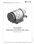
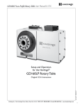
DD100 Direct-Drive Rotary Table Indexer User Manual B-160A Setup and Operation for the Hardinge® DD100 Direct-Drive Rotary Table Indexer Part No. BA -0009500-0160 Original U.S.A. Instructions Hardinge Inc. One Hardinge Drive, Elmira, New York U.S.A. 14902-1507 800.843.8801 (Canada 800.468.5946) www.shophardinge.com 1 DD100 Direct-Drive Rotary Table Indexer User Manual B-160A Thank you for purchasing a Hardinge DD100 Rotary Table Indexer! This User’s Manual is provided to assist you with setup procedures and to familiarize you with the features, specifications and maintenance recommendations of your unit. The mechanical indexing head can be maintained by the customer with proper cleaning and maintenance. Any necessary repairs required during the warranty period will be made at Hardinge Inc., or by a factory authorized representative. For best workholding results with this rotary table, Hardinge recommends Hardinge brand collets, 5C workholding products, step chucks, and expanding collets. Hardinge Inc. One Hardinge Drive Elmira, New York 14902-1507 U.S.A. p. 800.843.8801, or 607.378.4022 p. 800.468.5946 (Canada) f. 607.734.3886 Part No. BA -0009500-0160 2 Hardinge Inc. One Hardinge Drive, Elmira, New York U.S.A. 14902-1507 800.843.8801 (Canada 800.468.5946) www.shophardinge.com DD100 Direct-Drive Rotary Table Indexer User Manual B-160A Table of Contents Safety Recommendations. . . . . . . . . . . . . . . . . . . . . . . . . . . . . . . . . . . . . . . . . . . . . . . . . . . . . . . . . . . . . . . . . . . . . . . . . 4 1.Introduction 1.1 Basic Description. . . . . . . . . . . . . . . . . . . . . . . . . . . . . . . . . . . . . . . . . . . . . . . . . . . . . . . . . . . . . . . . . . . . . . 7 1.2 High Stiffness Overall System. . . . . . . . . . . . . . . . . . . . . . . . . . . . . . . . . . . . . . . . . . . . . . . . . . . . . . . . . . . . . 7 1.3 Machinable Part Size. . . . . . . . . . . . . . . . . . . . . . . . . . . . . . . . . . . . . . . . . . . . . . . . . . . . . . . . . . . . . . . . . . . . 7 1.4 Spindle Clamp Option . . . . . . . . . . . . . . . . . . . . . . . . . . . . . . . . . . . . . . . . . . . . . . . . . . . . . . . . . . . . . . . . . . 8 1.5Features. . . . . . . . . . . . . . . . . . . . . . . . . . . . . . . . . . . . . . . . . . . . . . . . . . . . . . . . . . . . . . . . . . . . . . . . . . . . . . 9 1.6 Motor Thermostat. . . . . . . . . . . . . . . . . . . . . . . . . . . . . . . . . . . . . . . . . . . . . . . . . . . . . . . . . . . . . . . . . . . . 10 1.7 Specifications . . . . . . . . . . . . . . . . . . . . . . . . . . . . . . . . . . . . . . . . . . . . . . . . . . . . . . . . . . . . . . . . . . . . . . . . 10 1.8Dimensions. . . . . . . . . . . . . . . . . . . . . . . . . . . . . . . . . . . . . . . . . . . . . . . . . . . . . . . . . . . . . . . . . . . . . . . . . . 11 2.Setup 2.1 2.2 2.3 2.4 2.5 2.6 General Setup. . . . . . . . . . . . . . . . . . . . . . . . . . . . . . . . . . . . . . . . . . . . . . . . . . . . . . . . . . . . . . . . . . . . . . . . Use of Collets, Chucks and Face Plates. . . . . . . . . . . . . . . . . . . . . . . . . . . . . . . . . . . . . . . . . . . . . . . . . . . . Hardinge Pneumatic High-Force and Fail-Safe Collet Closers . . . . . . . . . . . . . . . . . . . . . . . . . . . . . . . . . . Installing an Air-Actuated Collet Closer. . . . . . . . . . . . . . . . . . . . . . . . . . . . . . . . . . . . . . . . . . . . . . . . . . . Use of Collets with Hardinge Collet Closers. . . . . . . . . . . . . . . . . . . . . . . . . . . . . . . . . . . . . . . . . . . . . . . Tooling Locations. . . . . . . . . . . . . . . . . . . . . . . . . . . . . . . . . . . . . . . . . . . . . . . . . . . . . . . . . . . . . . . . . . . . . 12 13 14 15 16 18 3. Routine Maintenance 3.1 3.2 3.3 Use of Oil- and Water-Soluble Coolants. . . . . . . . . . . . . . . . . . . . . . . . . . . . . . . . . . . . . . . . . . . . . . . . . . . 19 Clean Up. . . . . . . . . . . . . . . . . . . . . . . . . . . . . . . . . . . . . . . . . . . . . . . . . . . . . . . . . . . . . . . . . . . . . . . . . . . . 19 Collet Key Replacement. . . . . . . . . . . . . . . . . . . . . . . . . . . . . . . . . . . . . . . . . . . . . . . . . . . . . . . . . . . . . . . . 19 Part No. BA -0009500-0160 4. One-Year Limited Warranty. . . . . . . . . . . . . . . . . . . . . . . . . . . . . . . . . . . . . . . . . . . . . . . . . . . . . . . . . . . . . . . . . . 19 Hardinge Inc. One Hardinge Drive, Elmira, New York U.S.A. 14902-1507 800.843.8801 (Canada 800.468.5946) www.shophardinge.com 3 DD100 Direct-Drive Rotary Table Indexer User Manual B-160A Safety Recommendations READ COMPLETE INSTRUCTIONS CAREFULLY BEFORE OPERATING THIS UNIT. Note: Equipment refers to the rotary table indexer and/or machine it is used with. When this instruction book was printed, the information given was current. However, since we are constantly improving the design of our products, it is possible that the illustrations and descriptions may vary from the current unit. - WARNING Occupational Safety and Health Administration (OSHA) Hazard Communication Standard 1910.1200, effective May 25, 1986, and various state "employee right-to-know laws" require that information regarding chemicals used with this equipment be supplied to you. Refer to the applicable section of the Material Safety Data Sheets supplied with your unit when handling, storing, or disposing of chemicals. HARDINGE SAFETY RECOMMENDATIONS Your Hardinge machine is designed and built for maximum ease and safety of operation. However, some previously accepted shop practices may not reflect current safety regulations and procedures, and should be re-examined to insure compliance with the current safety and health standards. Hardinge Inc. recommends that all shop supervisors, maintenance personnel, and machine tool operators be advised of the importance of safe maintenance, setup, and operation of Hardinge-built equipment. Our recommendations are described below. READ THESE SAFETY RECOMMENDATIONS BEFORE PROCEEDING ANY FURTHER. ANYONE HAVING ACTIVE IMPLANTS (pacemakers) or having any other ferromagnetic prosthesis is not qualified to work with these kinds of devices, or to approach them. Keep at a safe distance from the motor. READ THE APPROPRIATE MANUAL OR INSTRUCTIONS before attempting operation or maintenance of the equipment. Make certain that you understand all instructions. DO NOT ALLOW the operation or repair of equipment by untrained personnel. CONSULT YOUR SUPERVISOR when in doubt as to the correct way to do a job. WEAR SAFETY GLASSES AND PROPER FOOT PROTECTION at all times. When necessary, wear respirator, helmet, gloves and ear muffs or plugs. DON’T OPERATE EQUIPMENT unless proper maintenance has been regularly performed and the equipment is known to be in good working order. WARNING or INSTRUCTION TAGS are mounted on the unit for your safety and information. Do not remove them or damage them. DO NOT ALTER THE EQUIPMENT to bypass any interlock, overload, disconnect, or other safety device. DO NOT OPERATE EQUIPMENT if unusual or excessive heat, noise, smoke or vibration occurs. Report any excessive or unusual vibration, sounds, smoke or heat as well as any damaged parts. LIFTING AND HANDLING OF THE UNIT should be done with full knowledge of the unit weight and using proper procedures. MAKE CERTAIN that the equipment is properly grounded. Consult National Electric Code and all local codes. REMOVE POWER from the unit by unplugging the power cord before attempting repair or maintenance. (Where Applicable) DON’T TOUCH ELECTRICAL EQUIPMENT when hands are wet or when standing on a wet surface. (Where Applicable) REPLACE BLOWN FUSES with fuses of the same size and type as originally furnished. (Where Applicable) ASCERTAIN AND CORRECT the cause of a shutdown caused by overload heaters before restarting the machine. (Where Applicable) 4 Hardinge Inc. One Hardinge Drive, Elmira, New York U.S.A. 14902-1507 800.843.8801 (Canada 800.468.5946) www.shophardinge.com Part No. BA -0009500-0160 DON’T OPEN THE CONTROL BOX without consulting with Hardinge. (Where Applicable) DD100 Direct-Drive Rotary Table Indexer User Manual B-160A Safety Recommendations (continued) KEEP THE AREA AROUND THE MACHINE well lit and dry. KEEP CHEMICAL AND FLAMMABLE MATERIAL away from electrical or operating equipment. HAVE THE CORRECT TYPE OF FIRE EXTINGUISHER handy when machining combustible material and keep chips clear of the work area. DON’T USE a toxic or flammable substance as a solvent cleaner or coolant. MAKE CERTAIN THAT PROPER GUARDING is in place and that all doors to the primary machine are closed and secured. DON’T OPEN GUARD DOORS of the primary machine while any machine component is in motion. MAKE SURE chucks, closers, fixture plates, and all other spindle-mounted workholding devices are properly mounted and secured before starting the unit or the machine. MAKE CERTAIN all tools are securely clamped in position before starting the unit or the machine. REMOVE ANY LOOSE PARTS OR TOOLS left on the unit or the machine or in the work area before operating the equipment. Always check the machine and work area for loose tools and parts especially after work has been completed by maintenance personnel. REMOVE CHUCK WRENCHES before starting the unit or the machine. BEFORE PRESSING THE CYCLE START PUSH BUTTON, make certain that proper functions are programmed and that all controls are set in the desired modes. KNOW WHERE ALL STOP push buttons are located in case of an emergency. MAKE CERTAIN that all guards are in good condition and are functioning properly before operating the equipment. INSPECT ALL SAFETY DEVICES AND GUARDS to make certain that they are in good condition and are functioning properly before the cycle is started. CHECK THE POSITION of any load/unload automation before pressing the Cycle Start push button. CHECK SETUP,TOOLING AND SECURITY OF THE WORKPIECE if the machine has been OFF for any length of time. DRY CYCLE a new setup to check for programming errors. MAKE CERTAIN that you are clear of any "pinch point" created by moving slides before starting the machine. DON’T OPERATE any equipment while any part of the body is in the proximity of a potentially hazardous area. DON’T REMOVE CHIPS with hands. Use a hook or similar device and make certain that all machine movements have ceased. BE CAREFUL of sharp edges when handling a newly machined workpiece. DON’T REMOVE OR LOAD a workpiece while any part of the equipment is in motion. DON’T OPERATE ANY EQUIPMENT while wearing rings, watches, jewelry, loose clothing, neckties or long hair not contained by a net or shop cap. DON’T ADJUST tooling or coolant hoses while the equipment is running. DON’T LEAVE tools, workpieces or other loose items where they can come in contact with a moving component of the equipment. DON’T JOG SPINDLE in either direction when checking threads with a thread gage. DON’T ATTEMPT to brake or slow the equipment with hands or any makeshift device. ANY ATTACHMENT,TOOL OR MACHINE MODIFICATION not obtained from Hardinge Inc. must be reviewed by a qualified safety engineer before installation. Hardinge Inc. One Hardinge Drive, Elmira, New York U.S.A. 14902-1507 800.843.8801 (Canada 800.468.5946) www.shophardinge.com Part No. BA -0009500-0160 DON’T CHECK finishes or dimensions of workpiece near running spindle or moving slides. 5 DD100 Direct-Drive Rotary Table Indexer User Manual B-160A Safety Recommendations (continued) USE CAUTION around exposed mechanisms and tooling especially when setting up. Be careful of sharp edges on tools. DON’T USE worn or defective hand tools. Use the proper size and type for the job being performed. USE ONLY a soft-faced hammer on tooling and fixtures. DON’T USE worn or broken tooling on machine. MAKE CERTAIN that all tool mounting surfaces are clean before mounting tools. INSPECT ALL CHUCKING DEVICES daily to make certain that they are in good operating condition. Replace any defective chuck before operating the machine. USE MAXIMUM ALLOWABLE gripping pressure on the chuck. Consider weight, shape and balance of the workpiece. DON’T EXCEED the rated capacity of the equipment. DON’T LEAVE the equipment unattended while it is operating. DON’T CLEAN the equipment with an air hose. KEEP TOTE PANS a safe distance from the machine. Don’t overfill the tote pans. DON’T LET STOCK project past the back end of the collet closer or equipment spindle without being adequately covered and properly supported. UNLESS OTHERWISE NOTED, all operating and maintenance procedures are to be performed by one person. To avoid injury to yourself and others, be sure that all personnel are clear of the equipment when opening or closing the coolant guard door and any access covers. FOR YOUR PROTECTION - WORK SAFELY DON’T OPERATE THE EQUIPMENT with damaged or worn electrical cables. Part No. BA -0009500-0160 VERIFY that the electrical cables are not restrained or pinched during full travel movement of the machine. 6 Hardinge Inc. One Hardinge Drive, Elmira, New York U.S.A. 14902-1507 800.843.8801 (Canada 800.468.5946) www.shophardinge.com DD100 Direct-Drive Rotary Table Indexer User Manual B-160A 1. Introduction to the Hardinge® DD100 Direct-Drive Rotary Table Indexer 1.1 Basic Description The Hardinge® DD100 Direct-Drive Rotary Table Indexer is ideal for rapid and accurate positioning of small parts in machining operations such as milling, drilling, tapping, contouring, spiral milling and grinding. The Hardinge DD100 is a fully integrable, programmable, rotary positioning device. The mechanical indexing head holds the workpiece and is controlled by either the all-digital servo control or by a machine control as a true 4th axis. Positioning of the workpiece is accomplished by programming the angular movements into the memory of the servo control or by using the appropriate "G" codes and axis letter codes in the machine control just like a regular axis. It can be used as a slave to your CNC machine, as a master control unit in dedicated drilling operations, or as a true 4th axis to the machine. It can be used in the horizontal position or in some cases mounted vertically for face- and end-working applications. The DD100 has a foot print similar to that of the Hardinge 5C Rotary Indexer and is mounted the same way. The rotary table indexer also has a spindle clamp option to help assist the motor for off-axis drilling and milling applications while maintaining a fixed position. Advantages of the 5C DD100 Direct-Drive Rotary Table Indexer: • No Backlash • High Resolution Encoder Directly Mounted to Spindle • Long Life with Low Maintenance • Optimal Repeatability and Positioning Accuracy The DD100 is offered with a 200 volt frameless (wraparound rare-earth) permanent magnet torque motor and meets the most rigorous industry codes. It carries the same spindle centerline (4.00"/101.6mm) and tool clearance as most other rotary products for direct replacement without program changes. It can be mounted with the spindle horizontal or in some cases vertical depending on application. Cable connectors meet the IP 65 splash code that states that they can be splashed with coolant and not leak. The spindle is hardened and ground for accuracy and has a rigid crossed roller bearing and a cylindrical roller to support heavy cutting forces. The unit is designed with a series of appropriate sealing systems including a direct bearing seal and a front cap seal with air purge to provide a longer bearing life. Positioning of the spindle is accomplished through a wraparound rare-earth permanent magnet torque motor that requires no mechanical gears. This type of motor requires no maintenance and will provide many years of smooth operating performance with zero backlash. The system is fitted with a means of liquid cooling to the motor to double the continuous torque. The high resolution encoder is mounted directly to the spindle to insure the highest available accuracy. Dependent upon the control system used, the DD100 can yield a resolution of up to 655,360 counts per revolution. 1.2 High Stiffness Overall System The DD100 is inherently stiff due to its construction with the robust housing, crossed roller bearing in the front, and a tapered bore cylindrical roller bearing in the rear. Furthermore, the direct-drive motor offers a level of servo stiffness for the spindle that is superior to geared systems due to the elimination of gear backlash and other system compliances. The DD100 servo gain is aimed more towards high-speed positioning than it is for contouring. The DD100 Rotary Table Indexer is designed with a 5C spindle seat similar to the lathe spindle that Hardinge is noted for. The Hardinge DD100 has been designed for those parts that can be conveniently gripped in any of the 5C gripping systems that Hardinge is also noted for. Typical parts are in the range of approximately 1"/25.4mm in diameter and generally not longer than 6"/152.4mm without the use of a tailstock. It is typical to speak in terms of the L/D ratio, which is the length divided by the part diameter. A 2"/50.8mm diameter part 6"/152.4mm long has an L/D ratio of 3:1. Part pieces with larger L/D ratios should be used with a tailstock up to a typical L/D ration of 6:1. Larger part sizes than those described above can be handled with additional support (i.e. tailstock, trunnion, etc.). When talking about machinable part size, inertia and torque play an important role. Any part and fixture combination should not exceed the maximum inertia of 0.015 kg.m2. This inertia should be calculated about the center of rotation Hardinge Inc. One Hardinge Drive, Elmira, New York U.S.A. 14902-1507 800.843.8801 (Canada 800.468.5946) www.shophardinge.com Part No. BA -0009500-0160 1.3 Machinable Part Size 7 DD100 Direct-Drive Rotary Table Indexer User Manual B-160A of the DD100 because when a part's mass gets further from the center of rotation, its inertia increases. An unbalanced part should also not require a torque that exceeds the allowable torque of the motor shown in section 1.7 of this document. A part weighing 5 lbs at a distance of 6 inches from the center of the spindle would require 30 in-lbs or 2.5 ft-lbs of torque to rotate. See examples below for light parts that have high inertia. Note: Larger inertial loads may require changing a few motor parameters to get the unit to run properly. If assistance is needed in calculating inertia, torque, or changing parameters, please contact your local Hardinge representative. Inertia vs. Weight vs. Required Torque to Spin Part 2.0 0.6 AXIS OF ROTATION 3.5 1.0 AXIS OF ROTATION Example A Material: Steel Weight: 5.3 lbs/2.4 kg Inertia about axis of Rotation: 2.7 lb-in2 /0.0008 kg-m2 Torque required to turn Unbalanced Part: N/A (Balanced) Example B Material: Steel Weight: 2.5 lbs/1.1 kg Inertia about axis of Rotation: 17.8 lb-in2 /0.008 kg-m2 Torque required to turn Unbalanced Part: 7.5 in-lbs/0.85 Nm Example A is a balanced part which is approximately twice as heavy as Example B, which is an unbalanced part. Notice that since Example A is balanced, the torque required to hold the part in position is negligible and its moment of inertia is very low. Since Example B is unbalanced, its moment of inertia is about 10 times larger than Example A even though it weighs about half as much. Also, note that torque is required to hold Example B in position. The Hardinge® DD100 Direct-Drive Rotary Table Indexer is available with an optional fail-safe spindle clamp. This clamp allows the spindle to handle cutting forces equal to 100 ft-lb/136 Nm, allowing for greater cutting forces in the noncontouring mode of operation. The unit contains a pressure sensor that will prevent indexing in the event that air pressure drops below 85 psi to the clamp so that damage is prevented. Air is supplied to the clamp through the cable conduit and is either connected to the back of the control box or the machine air supply in the machine canopy wireway. When equipped with the Hardinge servo control, the clamp can be controlled automatically so that the clamp is engaged when the Rotary Table Indexer arrives at its programmed destination or it can be controlled with "G" codes. For ease of use, a "C" will appear on the display of the control whenever the clamp is engaged. There is a potential for a drop in air pressure if the air line supplying the Rotary Table Indexer is also supplying something else with air. If you receive a low pressure alarm, the first thing you should check is the air pressure supplied to the Rotary Table Indexer. Please note that even a momentary drop in air pressure can create an alarm situation. 8 Hardinge Inc. One Hardinge Drive, Elmira, New York U.S.A. 14902-1507 800.843.8801 (Canada 800.468.5946) www.shophardinge.com Part No. BA -0009500-0160 1.4 Spindle Clamp Option DD100 Direct-Drive Rotary Table Indexer User Manual B-160A CAUTION: Never attempt to defeat the clamp protection logic as this may result in an opportunity for the system to rotate when the clamp is engaged. This will cause an overload fault and repeated attempts to operate in this manner may damage the clamp. The clamp requires a minimum of 85psi OF DRY FILTERED AIR to fully release the spindle and must be supplied to the unit even if the clamp is not going to be used. 1.5 Features RIGID DESIGN Precision cross-roller bearing coupled with a tapered-bore cylindrical roller bearing will support heavy cutting forces on medium or small parts HARDENED AND GROUND SPINDLE Typical of the accurate long-life Hardinge lathe spindle WRAPAROUND RARE-EARTH PERMANENT MAGNET TORQUE MOTOR For very precise high-speed indexing with no backlash and high repeatability AUTOMATIC CIRCLE DIVISION (With Hardinge Servo Control) You can program a step that automatically divides a circle into any number of equal parts between 2 and 999 STOP/FEED-HOLD (With Hardinge Servo Control) You can use the STOP to feed-hold spindle movement without losing position on restart INTERFACING (With Hardinge Servo Control) Most CNC mills can be interfaced quickly and easily by using a spare "M" function which provides a switch-closer as a signal between your mill and the control. The Hardinge servo control will provide a finish set of contacts to send a response back to the mill. LINEAR & SPIRAL MILLING (With Hardinge Servo Control) For semi 4th-axis capability MEMORY (With Hardinge Servo Control) A nonvolatile memory retains your program even when power is turned off, and remembers the current spindle position and step number PROGRAM STORAGE (With Hardinge Servo Control) Store and recall up to fifty different programs USER PARAMETERS (With Hardinge Servo Control) Some of the parameters can be changed by the user to alter a few of the basic features of the servo control. PROGRAMMING (With Hardinge Servo Control) Program to rotate the spindle clockwise or counterclockwise with step sizes from .001 to 9999.99 degrees. Using G83 & G84, continuous rotation is allowed. Contact Hardinge for maximum speeds based on duty cycle. ABSOLUTE OR INCREMENTAL PROGRAMMING (With Hardinge Servo Control) Up to 1000 different steps can be stored in memory and each step can be repeated (looped) 999 times RS-232 INTERFACE (With Hardinge Servo Control) For computer control of sending and receiving programs and controlling the rotary table indexer via the CNC control of host machine capable of RS-232 communication SIMPLE EDITING (With Hardinge Servo Control) Edit a program by simply writing over existing steps, or inserting or deleting a line (or several lines) between steps, with automatic program line renumbering Hardinge Inc. One Hardinge Drive, Elmira, New York U.S.A. 14902-1507 800.843.8801 (Canada 800.468.5946) www.shophardinge.com Part No. BA -0009500-0160 RESOLUTION Standard resolution of .001 degrees 9 DD100 Direct-Drive Rotary Table Indexer User Manual B-160A SUBROUTINES (With Hardinge Servo Control) Allows repeated sequences up to 999 times, saving programming time and memory space VARIABLE FEED RATES Variable from .001 deg./sec. to 4200 deg./sec. with Hardinge Servo Control up to 3600 deg/sec as true 4th axis ZERO RETURN (With Hardinge Servo Control) An "automatic home" position can be programmed to return the spindle to its original starting position from any point ONE-YEAR WARRANTY The Hardinge DD100 Rotary Table System is provided with a 12-month, one-year warranty against any defects in material and workmanship. 1.6 Motor Thermostat The motor is equipped with a thermostat that monitors the internal temperature in the motor windings. The thermostat is set to open at 85 degrees Celsius, which is well below the maximum temperature allowed in the motor windings. 1.7 Specifications Spindle: Clamping Torque (ft-lb/Nm) 100/136 Runout Max. (TIR) 0.0002" Backlash (arc/sec) 0 Maximum RPM 450 with Servo Control @ 120 volt single phase 700 with Servo Control @ 220 volt single phase 600 as 4th Axis with 20 amp Fanuc Drive/Amplifier Rotational Speed (degrees/sec) 0.001 to 4200 with Servo Control 0.001 to 3600 as Fanuc 4th Axis Spindle Nose A2-4, 5C Collets Standard 5C Spindle center-to-base (inch) 4.000" ± 0.001 Indexing: Accuracy (arc/sec) ±3 Repeatability (arc/sec) ±2 Resolution (arc/sec) ±.077 Max Rotation/Step (degree) 9999.99 or Continuous Using G83 or G84 in the Servo Control Motor: Rare-Earth Permanent Magnet Torque Motor Maximum Torque (ft-lb/Nm) 28/38 Continuous Air-Cooled 1 (ft-lb/Nm) 3.8/5.2 Continuous Water-Cooled 1 (ft-lb/Nm) 7.5/10.2 Operating Specifications: Duty Cycle 100% at full speed Operating Temperature (max. ambient) 104°F/40°C Power Rating 115±5% @ 10 amps 2 Oil Requirements No Oil Air Requirements 85psi Minimum dry air for Optional Clamp 85psi Maximum dry air for Optional Collet Closer 1 - continuous torque available 24/7, 365 days, 2 - will vary according to motor requirements of the 4th-axis interface 10 Hardinge Inc. One Hardinge Drive, Elmira, New York U.S.A. 14902-1507 800.843.8801 (Canada 800.468.5946) www.shophardinge.com Part No. BA -0009500-0160 Weight: Rotary Table Indexer (lb/kg) 65/29.48 Control (lb/kg) 9.54/4.34 DD100 Direct-Drive Rotary Table Indexer User Manual B-160A Workholding: Collets-round (max. capacity) in/mm Collets-Hex (max. capacity) in/mm Collets-Square (max. capacity) in/mm Step Chucks (max. capacity) in/mm 3-Jaw Chucks (diameter) in/mm Sure-Grip® Expanding Collets in/mm Fixture Plate-Collet Style (diameter) Face Plate-Slotted with Angle Mounts (dia.) Collet Stops (part positioning) 11/16"/26.98 29/32"/23.01 ¾"/19.05 up to 4"/101.6 4"/101.6 1/8"-3"/3.17-76.20 33/8"/85.72, 43/8"/111.12 6"/170mm YES 1.8 Dimensions DD100 Rotary Table Indexer Unit 9.38 (238) 9.99 (253.7) 7.2 (182.9) FITTINGS FOR LIQUID COOLING THE MOTOR 4±.001 (101.6±.025) 6 (152.3) 3.38 (86) 3±.0003 (76.2±.007) 7.2 (183.8) 1.29 (32.8) 9.09 (229) 14.35 (364.5) 12.90 (327.7) Side View with High-Force Collet Closer Side View with Fail-Safe Collet Closer Hardinge Inc. One Hardinge Drive, Elmira, New York U.S.A. 14902-1507 800.843.8801 (Canada 800.468.5946) www.shophardinge.com Part No. BA -0009500-0160 5/8” OR 18MM (REMOVABLE LOCATING BUTTONS) 11 DD100 Direct-Drive Rotary Table Indexer User Manual B-160A 2. Set Up 2.1 General Setup 1. Fill out the warranty information by visiting "www.hardinge.com/rotarywarranty" on the internet. 2. Place the rotary table indexer on the machine. Route the cable from the head so that it avoids tool changers and table edges. Cable slack must be provided for your machine’s movements. If the cable is cut, the motor or feed back system could fail prematurely. Replace a damaged cable immediately. Secure the rotary table to the machine’s T-slot table as shown below (upright or on its back). A special mounting plate will be needed to mount the unit on its back if using a high-force collet closer. T-nut packages are available for purchase for various T-slot tables. Kit includes (2) T-nuts, (2) bolts and (2) flat washers. Check to verify that all clearances are satisfied in full machine axis’ movements, and that there is no possibility of a collision. NOTE: End user is responsible for properly routing the cable. Hardinge accepts no responsibility for damages in cabling resulting from improper installation. 3. Place the rotary table indexer in an area free from chips and coolant where air can circulate freely. Do not let chips pile up over the motor enclosure, as this would prevent proper cooling. 4. Connect the DD100 using one of the techniques as described in the Hardinge servo control or Hardinge 4th-axis manual which will be included with the mechanical unit. 5. If adding a rotary table indexer to a Hardinge mill using a remote CNC cable or as a true 4th axis, refer to the instructions in the Hardinge 4th-axis manual or call your Hardinge service representative. 6. If using the Hardinge servo control, secure it in its required placement. Do not cover any surface of the control, as it will quickly overheat. Do not place the unit on top of other hot electronic controls. a. The DD100 is wired directly to the Hardinge servo control. For control box placement and cable routing, the cable will need to be disconnected and reconnected according to the instructions in the Hardinge Servo control manual. b. Connect the AC line cord to a 120V AC grounded receptacle. The cord is a three-wire ground type and the ground must be connected. Power is 120VAC. The power service must supply a minimum of 15 amps continuously. Conduit wire must be 12 gauge or larger and fused for at least 20 amps. If an extension cord is to be used, use a three-wire ground type and the ground line must be connected. Avoid outlets that have large electric motors connected to them. Use only heavy-duty 12 gauge extension cords capable of 20 amp load. Do not exceed a length of 30 feet. Permanent installations should be hard-wired or installed with locking plugs. c. Semi-Fourth Axis: Connect the remote interface cable. See separate Hardinge Servo Control manual. 12 Hardinge Inc. One Hardinge Drive, Elmira, New York U.S.A. 14902-1507 800.843.8801 (Canada 800.468.5946) www.shophardinge.com Part No. BA -0009500-0160 CAUTION: Never connect or disconnect these cables with the power on. Instant failure will result. DD100 Direct-Drive Rotary Table Indexer User Manual B-160A 7. Connect air to the quick disconnect fitting on the back of the control box if unit is equipped with the spindle clamp option. CAUTION! If unit is equipped with the spindle clamp option, make sure air line connected to the control box is at least 85psi of dry filtered air. 8. Connect air to the quick disconnect fitting on top of the rotary table if unit is equipped with a pneumatic collet closer. This will supply both the Collet Closer and Air Purge with air. Shown with Pneumatic Collet closer Quick Disconnect Fitting Caution! Never use more than 85psi with the fail-safe collet closer. 9. If NOT using a pneumatic closer, connect air to the quick disconnect fitting on the side of the rotary table indexer for the air purge. 10. Save the packing materials in case you need to ship the unit. 11. At the end of the workday or shift, it is important to clean the rotary table indexer. The unit should be free of any chips or grime. Clean with a chip brush and apply a coat of rust preventative. CAUTION! Do not use an air gun around the front or rear seals. Chips may damage the seal if blown in with an air gun. NOTE: Prior to powering on the unit, read and understand the entire servo control or 4th axis manual. 12. Initialization and homing of the unit is explained in the servo control and the 4th axis manuals. 2.2 Use of Collets, Chucks, and Face Plates Part No. BA -0009500-0160 The unit accepts standard Hardinge® 5C collets, step chucks, ID gripping collets, manual chucks, face plates and fixture plates. When inserting the collets, align the keyway on the collet with the pin inside the spindle. Push the collet in and turn the collet drawbar clockwise until proper collet tightness is obtained. Detailed collet installation instructions for pneumatic collet closers are provided later in this section. Manual chucks and face plates utilize the A2-4 tapered nose on the spindle. We recommend using chucks that are 4"/101.6mm diameter or smaller and weigh less than 20 pounds. Pay special attention when installing manual chucks. Always make sure that the tapered nose and the outside diameter of the spindle are free of dirt and chips. Hardinge Inc. One Hardinge Drive, Elmira, New York U.S.A. 14902-1507 800.843.8801 (Canada 800.468.5946) www.shophardinge.com 13 DD100 Direct-Drive Rotary Table Indexer User Manual B-160A 2.3 Hardinge Pneumatic High-Force and Fail-Safe Collet Closers The DD100 is NOT provided with a collet closer as standard. However, a collet closer assembly can be ordered for the rotary table indexer that utilizes one of the available pneumatic closers. Hardinge offers two pneumatic collet closers, the Pneumatic Fail-Safe and the Pneumatic High-Force. Both of these closers provide an opportunity for operational improvements by reducing operator fatigue and allowing for possible automation arrangements. Both closers utilize an original Hardinge concept of force amplification that has been historically proven to provide long life and effective operation even under demanding applications. The Hardinge force amplifier, which is an integral part of the design, is a simple approach that allows high actuation forces with shop air pressure. The fail-safe design is spring-close, air-toopen allowing it to grip a part if air is lost in the shop, which is why it is called a "fail-safe." The High-Force Closer is air-to-close and is spring return, so it does not grip a part without air, but has higher available gripping forces. The High-Force Pneumatic Closer design can be set for varying gripping force levels by simply adjusting the incoming air pressure within the specified operating range. The following closers will accommodate the complete range of Hardinge 5C tooling including step chucks and internal Sure-Grip® expanding collet systems. Fail-Safe Collet Closer High-Force Collet Closer Pneumatic Fail-Safe Collet Closer CAUTION! Don’t exceed 85 psi while operating Fail-Safe Collet Closer as it my cause fatal damage to the closer and may cause injury to operator. Increasing air pressure will not aid in gripping of part piece as gripping forces come from internal springs. 14 Hardinge Inc. One Hardinge Drive, Elmira, New York U.S.A. 14902-1507 800.843.8801 (Canada 800.468.5946) www.shophardinge.com Part No. BA -0009500-0160 The Pneumatic Fail-Safe Collet Closer is a spring-close, air-to-open design for fail-safe operation. The part will remain clamped at an optimum 5C draw bar force of 1760 lbs/7829 N even if loss of air occurs. To release the part piece, apply maximum air pressure of 85 psi. A draw bar travel of .060"/1.5mm allows varying part diameter of .015"/.4mm. The 1.08"/27.4mm through-hole accommodates long parts and thru-coolant. The collet closer is designed so that the Rotary Table Indexer can be positioned vertically without the use of a spacer. DD100 Direct-Drive Rotary Table Indexer User Manual B-160A Pneumatic High-Force Collet Closer 5C High-Force Collet Closer FORCE CHART The Pneumatic High-Force Collet Closer is designed with a dual cylinder for greater available gripping force. This force can be regulated by adjusting the air pressure, but the force needs to be set according to levels below the maximum allowed for the workholding system. Much like the Fail-Safe closer, the total travel of this unit is .060"/1.5mm, but the through hole is only .311"/7.90mm. This means that the diameter variation or loading clearance of .015"/.4mm can be realized without adjustment and that the collet can be secured from the rear. Figure 1 Air Pressure (psi) Drawbar Force (lbs) 10 278 20 557 30 835 40 1113 50 1391 60 1670 70 1948 80 2226 90 2505 100 2783 Figure 2 Collet closer installation and alignment is critical if collet closers are going to be used during high-speed continuous rotation. It is recommended that collet closers are installed at the factory. However, in the event that a field installation of a closer is required, the following instructions can be used. Power down the system by first pushing the STOP button and turning off the control box or 4th-axis control. Remove any spindle tooling from the A2-4 spindle nose. Remove the button head screws holding the valve on the top of the closer adapter. Remove the snap ring from the rear of the closer and remove the slip ring and air valve as an assembly. If removing a fail-safe closer, use two dowel pins in the spanner holes on the back of the closer. These pins need to be long enough that a wrench can be placed across both pins and used to unthread the closer from the spindle. Two M10 bolts should be used in the face of the spindle to keep the spindle from rotating as the collet closer is unthreaded. If removing a high-force closer, use a strap wrench around the body of the closer to unthread it from the spindle. Replace the copper fittings with the correct size fitting for the closer you are going to install. Make sure the new collet closer has a draw bar adapter secured with lock-tite to the draw bar of the closer as seen in figure 1. Cut a piece of copper tubing to go from the closer to the valve. The fail-safe closer uses 1/8" OD copper tubing and the high force closer uses ¼" OD copper tubing. You may have to do a couple of trial fittings to get the copper tubing the correct length. If installing a high-force closer, tighten with a strap wrench on the main body to approximately 30 ft-lbs. If installing a fail-safe closer, remove the rear slip ring by first removing the snap ring holding it on. Removing the slip ring will allow access to four spanner holes on the back face of the closer body. Insert dowel pins into the spanner holes that are long enough so that an adequate amount of the pins Hardinge Inc. One Hardinge Drive, Elmira, New York U.S.A. 14902-1507 800.843.8801 (Canada 800.468.5946) www.shophardinge.com Part No. BA -0009500-0160 2.4 Installing an Air-Actuated Collet Closer 15 DD100 Direct-Drive Rotary Table Indexer User Manual B-160A stick out to put a wrench across them. Use a wrench to contact both dowel pins and turn the collet closer clockwise until tight. CAUTION! The High-Force Collet Closer relies on air pressure to maintain clamping force and will release if the air supply is accidentally removed. If this presents a fail-safe problem, then an air switch should be installed in-line to stop machining operations if the air supply should fail or purchase a fail-safe collet closer. 2.5 Use of Collets With Hardinge Collet Closers NOTE: All collets must be free from burrs and in good condition. Collet Installation for High-Force Collet Closer Part No. BA -0009500-0160 To install a collet, align the collet keyway with the spindle key and insert the collet. Insert a 5/16" hex wrench into the hex in the back of the draw tube, and turn the draw tube to engage the collet. Turn the draw tube until the collet grips the part, and then back off approximately 1/4 turn. This will be a good starting point for fine tuning the grip range. If using a collet larger than the 5/16" hex wrench, then the wrench can be inserted in the drawtube through the front of the collet for adjustment as well. 16 Hardinge Inc. One Hardinge Drive, Elmira, New York U.S.A. 14902-1507 800.843.8801 (Canada 800.468.5946) www.shophardinge.com DD100 Direct-Drive Rotary Table Indexer User Manual B-160A If the Collet is Sticking NOTE: To prevent excessive wear and collet sticking, make sure collets are in good condition and free from burrs. A light coat of Molybdenum grease on the collet wear surfaces will extend the life of the spindle and/or collet and help prevent sticking, especially when operating dry. Emergency collets are soft and are not recommended for long production runs. These collets will stick after prolonged use. When using the High-Force Collet Closer, releasing a collet is accomplished by removing the air supply. It is then pushed out by a heavy spring inside the collet closer. The High-Force Collet Closer uses shop air to pull the drawtube in and a heavy internal spring to push the draw tube out and release the collet. If, after repeated use, the spring will not push the collet out, use one of the following methods to remove the collet and lubricate the outside of the collet with a light grease film before reinserting: 1. If the optional three-way air valve provided with the unit becomes clogged with contaminates, the exhaust airflow may be restricted, which may cause the collet to stick in the taper. If this situation arises, leave the valve in the clamped position, then connect and disconnect the air supply several times in rapid succession. Part No. BA -0009500-0160 2. If the above procedure does not free the collet, switch the valve to the unclamped position, then gently tap the back end of the drawtube with a plastic-faced mallet. Hardinge Inc. One Hardinge Drive, Elmira, New York U.S.A. 14902-1507 800.843.8801 (Canada 800.468.5946) www.shophardinge.com 17 DD100 Direct-Drive Rotary Table Indexer User Manual B-160A Collet Installation for Fail-Safe Collet Closer To install a collet, align the collet keyway with the spindle key and insert the collet. Use the provided knurled tool to turn the back of the collet closer drawtube. Turn the drawtube several times to get the collet started in the drawtube. Actuate the air valve to put air in the closer and move the drawtube to the forward position, or open position. Continue to turn the drawtube until the collet grips the part and back the collet out of the drawtube ¼ to ½ of a turn so that the part easily slips in and out of the collet. Never try to turn the drawtube while the collet is gripping a part as the friction is too high inside the closer to allow the drawtube to turn. Never under any circumstances should a wrench be put on the drawtube knurled tool to aid in tightening or loosening a collet. Any method of adjusting a collet other than by hand can break the closer and void any warranty by Hardinge Inc. If at any time the drawtube is too hard to turn by hand, call Hardinge for assistance, do not use other tools to try and break it free. 2.6 Tooling Locations 6.61 (168) NOTE: 0.625"/15.9mm and 18mm plugs are supplied as standard. Plugs can be turned down to another diameter to accommodate tables with different slot dimensions. 18 Hardinge Inc. One Hardinge Drive, Elmira, New York U.S.A. 14902-1507 800.843.8801 (Canada 800.468.5946) www.shophardinge.com Part No. BA -0009500-0160 The DD100 is equipped with tooling points in order to speed setups. One of the most time-consuming procedures in setup is aligning the head with the table. On the mounting surfaces there are two 0.500"/12.7mm bored holes on 3.000"/76.2mm centers. The holes on the bottom surface are parallel to the spindle within 0.001"/0.025mm per 6 inches/152.5mm and on center within ±0.001"/0.025mm. By boring machine holes in your tooling plate, setups become routine. Using the tooling holes will also prevent the head from shifting on the mill table when the part is subjected to heavy cutting forces. On CNC mills, a machined stepped plug of 0.500"/12.7mm diameter one side and 0.625"/15.9mm on the other comes with the Hardinge head. The 0.625"/15.9mm diameter fits into the T-slot of the mill table. This will give quick parallel alignment that will be close enough for most jobs. DD100 Direct-Drive Rotary Table Indexer User Manual B-160A 3. ROUTINE MAINTENANCE 3.1 Use of Oil- and Water-Soluble Coolants For the use of oil- and water-soluble coolants, the following guidelines should be observed: • • DO NOT SUBMERGE THE UNIT IN COOLANTS. To the extent possible, direct the coolant lines to the work piece as opposed to directly upon the spindle seal area. Avoid high-pressure coolant applications where the pressure is above 200 psi. Some machining centers provide flood coolant at enormous rates so that the head is practically submerged. Throttle the flow back to appropriately match the application. Inspect the cables and gaskets regularly for cuts or swelling. Damage must be repaired immediately. 3.2 Clean Up At the end of the workday or shift, it is important to clean the rotary table indexer. The head should be free of any chips or grime. Clean with a chip brush and apply a coat of rust preventative. Do not use an air gun around front or rear seals. Chips may damage seal if blown in with an air gun. 3.3 Collet Key Replacement Remove the set screw in the collet key access hole located on the spindle and then remove the old collet key from the face of the spindle with a 3mm Allen wrench. Replace the collet key with Hardinge P/N RT-0000283K only using pipe sealant or thread locker/sealer when installing. Screw the collet key into the spindle until it begins to protrude into the inside diameter and turn it until the flat on the bottom of key is parallel to spindle centerline. Place a new Hardinge collet into the spindle to test that key depth is adequate and then replace the set screw back into the key access hole using pipe sealant. NOTE: When using collet type workholding, never run the spindle without the collet key having been properly installed. Failure to do this may cause the collet to rotate in the spindle and possibly cause damage. 4. One-Year Limited Warranty Part No. BA -0009500-0160 The Hardinge Direct-Drive DD100 Rotary Table Indexer is provided with a 12-month, one-year warranty against any defects in material and workmanship. Specific details of the warranty can be found in the Hardinge Terms and Conditions document associated with the purchase agreement. Hardinge Inc. One Hardinge Drive, Elmira, New York U.S.A. 14902-1507 800.843.8801 (Canada 800.468.5946) www.shophardinge.com 19 Hardinge Inc. One Hardinge Drive | P.O. Box 1507 | Elmira, New York 14902-1507 USA USA: 800-843-8801 | Canada: 800-468-5946 | Fax: 607-734-3886 To Order Online: www.shophardinge.com | Corporate Homepage: www.hardinge.com | E-mail: [email protected] | Live Online Support: www.shophardinge.com All specifications are subject to change without notice due to ongoing continuous improvement. All marks indicated by ® and ™ are trademarks of Hardinge Inc. Instruction Manual B-160A • Litho in USA • ©Hardinge Inc. 2012