1
Servo Control User Manual B-158B
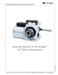
Setup and Operation
for the Hardinge®
Standard, Enhanced and Direct-Drive
Rotary Servo Controls
Original U.S.A. Instructions
Hardinge Inc. One Hardinge Drive, Elmira, New York U.S.A. 14902-1507 800.843.8801 (Canada 800.468.5946) www.shophardinge.com
Part No. BB -0009500-0158
Software Version 2.9.a
1
Servo Control User Manual B-158B
Safety Recommendations
READ COMPLETE INSTRUCTIONS CAREFULLY BEFORE OPERATING THIS UNIT. Note: Equipment refers to the
Hardinge Servo Control, rotary table indexer and/or machine it is used with.
When this instruction book was printed, the information given was current. However, since we are constantly improving
the design of our products, it is possible that the illustrations and descriptions may vary from the system.
- WARNING Occupational Safety and Health Administration (OSHA) Hazard Communication Standard 1910.1200, effective May
25, 1986, and various state "employee right-to-know laws" require that information regarding chemicals used with this
equipment be supplied to you. Refer to the applicable section of the Material Safety Data Sheets supplied with your unit
when handling, storing or disposing of chemicals.
HARDINGE SAFETY RECOMMENDATIONS
Your Hardinge Servo Control is designed and built for maximum ease and safety of operation. However, some previously accepted shop practices may not reflect current safety regulations and procedures, and should be re-examined to
insure compliance with the current safety and health standards.
Hardinge Inc. recommends that all shop supervisors, maintenance personnel, and machine tool operators be advised
of the importance of safe maintenance, setup and operation of Hardinge-built equipment. Our recommendations are
described below.
READ THESE SAFETY RECOMMENDATIONS BEFORE PROCEEDING ANY FURTHER.
ANYONE HAVING ACTIVE IMPLANTS (pacemakers) or having any other ferromagnetic prosthesis is not qualified to
work with these kinds of devices, or to approach them. Keep at a safe distance from the motor.
READ THE APPROPRIATE MANUAL OR INSTRUCTIONS before attempting operation or maintenance of the
equipment. Make certain that you understand all instructions.
DO NOT ALLOW the operation or repair of equipment by untrained personnel.
CONSULT YOUR SUPERVISOR when in doubt as to the correct way to do a job.
WEAR SAFETY GLASSES AND PROPER FOOT PROTECTION at all times. When necessary, wear respirator, helmet,
gloves and ear muffs or plugs.
DON’T OPERATE EQUIPMENT unless proper maintenance has been regularly performed and the equipment is known
to be in good working order.
WARNING or INSTRUCTION TAGS are mounted on the unit for your safety and information. Do not remove them
or damage them.
DO NOT ALTER THE EQUIPMENT to bypass any interlock, overload, disconnect or other safety device.
DO NOT OPERATE EQUIPMENT if unusual or excessive heat, noise, smoke or vibration occurs. Report any excessive
or unusual vibration, sounds, smoke or heat as well as any damaged parts.
LIFTING AND HANDLING OF THE UNIT should be done with full knowledge of the unit weight and using proper
procedures.
MAKE CERTAIN that the equipment is properly grounded. Consult National Electric Code and all local codes.
REMOVE POWER from the unit by unplugging the power cord before attempting repair or maintenance.
(Where Applicable)
DON’T TOUCH ELECTRICAL EQUIPMENT when hands are wet or when standing on a wet surface.
(Where Applicable)
REPLACE BLOWN FUSES with fuses of the same size and type as originally furnished. (Where Applicable)
2
Hardinge Inc. One Hardinge Drive, Elmira, New York U.S.A. 14902-1507 800.843.8801 (Canada 800.468.5946) www.shophardinge.com
Part No. BB -0009500-0158
DON’T OPEN THE CONTROL BOX without consulting with Hardinge.
Servo Control User Manual B-158B
Safety Recommendations (continued)
ASCERTAIN AND CORRECT the cause of a shutdown caused by overload heaters before restarting the machine.
(Where Applicable)
KEEP THE AREA AROUND THE EQUIPMENT well lit and dry.
KEEP CHEMICAL AND FLAMMABLE MATERIAL away from electrical or operating equipment.
HAVE THE CORRECT TYPE OF FIRE EXTINGUISHER handy when machining combustible material and keep chips
clear of the work area.
DON’T USE a toxic or flammable substance as a solvent cleaner or coolant.
MAKE CERTAIN THAT PROPER GUARDING is in place and that all doors to the primary machine are closed and
secured.
DON’T OPEN GUARD DOORS of the primary machine while any machine component is in motion.
MAKE SURE chucks, closers, fixture plates and all other spindle-mounted workholding devices are properly mounted
and secured before starting the unit or the machine.
MAKE CERTAIN all tools are securely clamped in position before starting the unit or the machine.
REMOVE ANY LOOSE PARTS OR TOOLS left on the unit or the machine or in the work area before operating the
equipment. Always check the machine and work area for loose tools and parts especially after work has been completed by maintenance personnel.
REMOVE CHUCK WRENCHES before starting the unit or the machine.
BEFORE PRESSING THE CYCLE START PUSH BUTTON, make certain that proper functions are programmed and
that all controls are set in the desired modes.
KNOW WHERE ALL stop push buttons are located in case of an emergency.
MAKE CERTAIN that all guards are in good condition and are functioning properly before operating the equipment.
INSPECT ALL SAFETY DEVICES AND GUARDS to make certain that they are in good condition and are functioning
properly before the cycle is started.
CHECK THE POSITION of any load/unload automation before pressing the Cycle Start push button.
CHECK SETUP, TOOLING AND SECURITY OF THE WORKPIECE if the machine has been OFF for any length of time.
DRY CYCLE a new setup to check for programming errors.
MAKE CERTAIN that you are clear of any "pinch point" created by moving slides before starting the machine.
DON’T OPERATE any equipment while any part of the body is in the proximity of a potentially hazardous area.
DON’T REMOVE CHIPS with hands. Use a hook or similar device and make certain that all machine movements have
ceased.
BE CAREFUL of sharp edges when handling a newly machined workpiece.
DON’T REMOVE OR LOAD a workpiece while any part of the equipment is in motion.
DON’T OPERATE ANY EQUIPMENT while wearing rings, watches, jewelry, loose clothing, neckties or long hair not
contained by a net or shop cap.
DON’T LEAVE tools, work pieces or other loose items where they can come in contact with a moving component
of the equipment.
DON’T CHECK finishes or dimensions of workpiece near running spindle or moving slides.
DON’T JOG SPINDLE in either direction when checking threads with a thread gage.
DON’T ATTEMPT to brake or slow the equipment with hands or any makeshift device.
Hardinge Inc. One Hardinge Drive, Elmira, New York U.S.A. 14902-1507 800.843.8801 (Canada 800.468.5946) www.shophardinge.com
Part No. BB -0009500-0158
DON’T ADJUST tooling or coolant hoses while the equipment is running.
3
Servo Control User Manual B-158B
Safety Recommendations (continued)
ANY ATTACHMENT, TOOL OR MACHINE MODIFICATION not obtained from Hardinge Inc. must be reviewed by
a qualified safety engineer before installation.
USE CAUTION around exposed mechanisms and tooling especially when setting up. Be careful of sharp edges on tools.
DON’T USE worn or defective hand tools. Use the proper size and type for the job being performed.
USE ONLY a soft-faced hammer on tooling and fixtures.
DON’T USE worn or broken tooling on machine.
MAKE CERTAIN that all tool mounting surfaces are clean before mounting tools.
INSPECT ALL CHUCKING DEVICES daily to make certain that they are in good operating condition. Replace any
defective chuck before operating the machine.
USE MAXIMUM ALLOWABLE gripping pressure on the chuck. Consider weight, shape and balance of the workpiece.
DON’T EXCEED the rated capacity of the equipment.
DON’T LEAVE the equipment unattended while it is operating.
DON’T CLEAN the equipment with an air hose.
KEEP TOTE PANS a safe distance from the machine. Don’t overfill the tote pans.
DON’T LET STOCK project past the back end of the collet closer or equipment spindle without being adequately
covered and properly supported.
UNLESS OTHERWISE NOTED, all operating and maintenance procedures are to be performed by one person. To avoid
injury to yourself and others, be sure that all personnel are clear of the equipment when opening or closing the coolant
guard door and any access covers.
FOR YOUR PROTECTION - WORK SAFELY
DON’T OPERATE THE EQUIPMENT with damaged or worn electrical cables.
Part No. BB -0009500-0158
VERIFY that the electrical cables are not restrained or pinched during full travel movement of the machine.
4
Hardinge Inc. One Hardinge Drive, Elmira, New York U.S.A. 14902-1507 800.843.8801 (Canada 800.468.5946) www.shophardinge.com
Servo Control User Manual B-158B
Table of Contents
Safety Recommendations …………………………………………………………………………………………
3
1. Introduction
1.1
Five Ways to Configure a Hardinge® Rotary Product to your Machine ………………………………
7
1.2 Three Variations of the Hardinge Servo Control ………………………………………………………
7
2. Servo Control Operation
2.1 Front Panel Controls and Display ……………………………………………………………………
9
2.2 Rear Panel ……………………………………………………………………………………………… 10
2.3 Dimensions…………………………………………………………………………………………… 11
2.4 Turning ON the Servo Control ……………………………………………………………………… 11
2.5 Three Basic Servo Control Modes - RUN, PROGRAM and PARAMETER …………………………… 13
3. Programming the Servo Control
3.1
Feed Rate (F) ………………………………………………………………………………………… 15
3.2 Step (N) ……………………………………………………………………………………………… 15
3.3
Position (P) …………………………………………………………………………………………… 15
3.4
G-Codes (G) ………………………………………………………………………………………… 15
3.5
Loop Count (L) ……………………………………………………………………………………… 16
3.6
Inserting a Step in a Program………………………………………………………………………… 16
3.7
Deleting a Step in a Program…………………………………………………………………………… 16
3.8
Selecting a Stored Program…………………………………………………………………………… 16
3.9
Clearing a Program…………………………………………………………………………………… 16
3.10 Software Limit Switch Function……………………………………………………………………… 17
4.1
Example 1 utilizing G91, G28 and G99………………………………………………………………… 18
4.2
Example 2 utilizing G28, G91 and G99 with Loop Count…………………………………………… 19
4.3
Example 3 utilizing G90, G99 and G88………………………………………………………………… 19
4.4
Example 4 utilizing G98 and G99……………………………………………………………………… 20
4.5
Example 5 utilizing G85 and G99……………………………………………………………………… 20
4.6
Example 6 utilizing G83, G84, G94 and G99 ………………………………………………………… 20
4.7
Example 7 utilizing Spiral Milling……………………………………………………………………… 22
4.8
Example 8 utilizing G95, G96, G97, G88 and G99…………………………………………………… 23
5.
Features of the Enhanced Servo Control
5.1
Clamp Circuit Schematic ……………………………………………………………………………… 24
5.2
Clamp Theory Operation ……………………………………………………………………………… 24
5.3 Clamp Functionality of the Enhanced Servo Control………………………………………………… 25
5.4
Tips for Clamp Use…………………………………………………………………………………… 26
5.5
General Purpose OUTPUT Functions………………………………………………………………… 26
5.6
General Purpose INPUT Functions…………………………………………………………………… 28
5.7
Using the Inputs to Monitor Hardware Limit Switches……………………………………………… 30
Hardinge Inc. One Hardinge Drive, Elmira, New York U.S.A. 14902-1507 800.843.8801 (Canada 800.468.5946) www.shophardinge.com
Part No. BB -0009500-0158
4. Programming Examples 5
Servo Control User Manual B-158B
5.8
Using the Optional Hardinge Hardware Limit Switch Kit…………………………………………… 30
5.9
Homing the Rotary Indexer using the Hardware Limit Switch Kit…………………………………… 30
5.10 Adjusting Hardware Limit Switches…………………………………………………………………… 31
5.11 Cooling Fan for the Enhanced Servo Control………………………………………………………… 31
5.12 External Stop Circuit Function of the Enhanced Servo Control……………………………………… 31
6.
Interfacing to your Host Machine
6.1
Remote CNC Cable Connection and Use…………………………………………………………… 32
6.2
RS-232 Capabilities…………………………………………………………………………………… 33
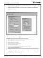
6.2.1 Configuring the PC using HyperTerminal……………………………………………………… 34
6.2.2 Uploading and Downloading Programs………………………………………………………… 37
6.2.3 Using a PC to Command the Servo Control………………………………………………… 38
6.2.4 Multiple Controls using RS-232 (Daisy-Chaining)……………………………………………… 39
6.3
Remote Operation with a FANUC CNC Control…………………………………………………… 40
6.4
Infrared Sensor Capabilities…………………………………………………………………………… 42
7.
Control Parameters
7.1
Parameter Definitions and Settings…………………………………………………………………… 44
7.2
Gear Compensation…………………………………………………………………………………… 56
7.3
Default Parameter Settings for Hardinge Standard Rotary Products………………………………… 57
7.4
Motors Approved for Use with the Hardinge Rotary Indexer Servo Control……………………… 58
8.
Control Message Information
8.1
Error Codes…………………………………………………………………………………………… 58
8.2
Servo OFF Codes ……………………………………………………………………………………… 59
8.3
Hardinge Informational Messages …………………………………………………………………… 59
9.
Hardware Supported by the Rotary Indexer Servo Control
9.1
Power and Encoder Cable …………………………………………………………………………… 60
9.2
Remote CNC Cable …………………………………………………………………………………… 60
9.3
Home Switch ………………………………………………………………………………………… 61
9.4
Pneumatic Clamp Valve ………………………………………………………………………………… 61
9.5
Clamp Pressure Switch ……………………………………………………………………………… 62
9.6
Control Support Options …………………………………………………………………………… 63
9.7
Direct-Drive Servo Control …………………………………………………………………………… 64
10.1 Testing the Remote CNC Cable and Cycle Start/Finish Circuit ……………………………………… 64
10.2 Inspecting Encoder/Power Cable ……………………………………………………………………… 65
10.3 Checking the Pressure Switch………………………………………………………………………… 66
10.4 Pin Schematic for the Encoder/Power Cable ………………………………………………………… 67
10.5 Checking the Clamp Valve …………………………………………………………………………… 68
11.Warranty ……………………………………………………………………………………………………… 68
G-Code Reference Chart ………………………………………………………………………………………… 68
6
Hardinge Inc. One Hardinge Drive, Elmira, New York U.S.A. 14902-1507 800.843.8801 (Canada 800.468.5946) www.shophardinge.com
Part No. BB -0009500-0158
10.Troubleshooting
Servo Control User Manual B-158B
1. Introduction
The following information will be used to help you become familiar with the operation of the Hardinge® Servo
Control. This information is written for the Standard and Enhanced Servo Controls utilizing software versions up
to version 2.9.a. Hardinge rotary products can be utilized in various ways by the operator to perform simple to very
complicated tasks.
1.1 Five Ways to Configure a Hardinge Rotary Product to your Machine:
1. As a stand-alone unit with a control. Programming is done in the rotary indexer servo control and executing
the program is done through the cycle start button on the control.
2. As an add-on to a host machine via the remote CNC cable. Programming is done in the indexer servo
control and the program is executed through a start signal via the remote CNC cable. This start signal can be
provided by a mechanical switch (the remote quill switch) or by a relay contact from the host machine control
using an M-code.
3. As an add-on to a host machine utilizing RS-232 communication. The servo control has the ability
to communicate with a host machine capable of RS-232 programming commands. Programming is done in
the host machine control and commands are sent through the RS-232 cable. The rotary table indexer servo
control interprets these commands and executes them. No programming is required in the rotary table
indexer servo control.
4. As an add-on to a host machine using the RS-232 communication and remote CNC cable in conjunction.
This is the most reliable use of the rotary indexer with the servo control. Programming is done in the host
machine control and commands are communicated over the RS-232 cable. The machine then uses an M-code
to send the start signal through the remote CNC cable and the rotary indexer servo control will execute the
commanded motion. The rotary indexer servo control then sends a finish signal to the host machine control
to cancel the M-code. No programming in the rotary indexer servo control is required.
5. As a true 4th-axis to the machine CNC control. This configuration removes the rotary indexer servo
control from the application and the rotary product is wired directly to the machine. A rotary unit purchased
with a servo control may not be convertible to a true 4th-axis configuration. A compatible motor to the host
machine is required at time of purchase. When using the rotary product wired directly to the machine, consult
the host machine manufacturer for information on 4th-axis operation.
This manual will outline in detail the operation and programming
of the servo control configured in methods 1-4.
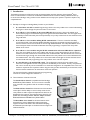
The Standard Servo Control is compatible with the Hardinge
GD5C2 Rotary Table Indexers. This servo control is intended
to be used with rotary products that do not utilize a clamping
system.
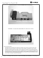
The Enhanced Servo Control has all the features of the standard
control, plus it has the ability to control a clamp circuit for the
rotary indexer as well as input and output features which can be
beneficial for the customer. The enhanced servo control is compatible with the Hardinge GD5C2, GD16C2, GD3J2, GD160LP,
GD210LP, DD100 and DD200 Rotary Table Indexers.
The Direct-Drive Servo Control has all of the features of the
enhanced servo control. Advanced G-code programming
supports hardware and software limit switches and clamping.
An additional input and output on the back of the unit support air
intake and exhaust.
Hardinge Inc. One Hardinge Drive, Elmira, New York U.S.A. 14902-1507 800.843.8801 (Canada 800.468.5946) www.shophardinge.com
Part No. BB -0009500-0158
1.2Three Variations of the Servo Control
7
Servo Control User Manual B-158B
All Hardinge Servo Controls are CE certified. The Enhanced Servo Controls for geared indexers are also offered
in a CSA version for sale in Canada.
Part Number
Hardinge Servo Control
CIA 0003279CE
Standard Hardinge Servo Control (phasing out in 2010, substitute CI 00032791OL)
CIA 0003279IO
CIA 0003279IOCS
N/A
IMPORTANT! A servo control is configured and tuned to the mechanical rotary table indexer unit with which
it ships. Substituting controls with mechanical units is not recommended unless you are advised to do so by a
Hardinge technician for troubleshooting purposes. Prior to substituting any control with a different mechanical unit,
contact the Hardinge technical department for approval. Failure to do so will void any and all warranties on
all involved products.
Part No. BB -0009500-0158
Enhanced Hardinge Servo Control
Enhanced Hardinge Servo Control, CSA Approved
Direct-Drive Servo Control
8
Hardinge Inc. One Hardinge Drive, Elmira, New York U.S.A. 14902-1507 800.843.8801 (Canada 800.468.5946) www.shophardinge.com
Servo Control User Manual B-158B
2. Servo Control Operation
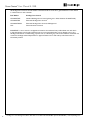
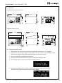
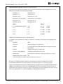
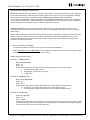
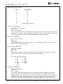
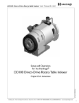
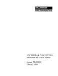
2.1 Front Panel Controls and Display
M
L
A
K
J
E
B
C
D
I
F
G
H
A. Enclosure cover
B. CYCLE START button begins a step, stops a continued operation, inserts a step or turns the Servo on
C. STOP button turns off the Servo when on and aborts a step in progress
D. JOG causes the Servo to move in either the Forward or Backward direction at a rate defined by the last
numeric key pressed – 9 is the fastest and 0 is the slowest
E. Infrared sensor for receiving and transferring program data
F. ZERO RETURN causes the Servo to return to HOME position, search for mechanical HOME, delete a
step or move forward to the mechanical offset
WARNING: In Parameter Mode, ZERO RETURN resets the parameters to a set of default settings which
may not be compatible with current unit.
G. ZERO SET key clears the entered data or defines the present Servo position as HOME
H. MINUS KEY selects negative step values or Program/Upload/Download functions
I.
STEP SCAN scans step numbers from 1 through 1000
J.
DISPLAY SCAN scans fields in PROGRAM mode
L. Data entry keys and jog speed selection
M. Four line display, each having twenty characters – a large amount of data can be viewed on one screen to
reduce scrolling and simplify programming steps
Hardinge Inc. One Hardinge Drive, Elmira, New York U.S.A. 14902-1507 800.843.8801 (Canada 800.468.5946) www.shophardinge.com
Part No. BB -0009500-0158
K. MODE/RUN PROG switches from RUN mode to PROGRAM mode
9
Servo Control User Manual B-158B
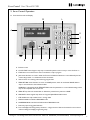
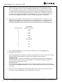
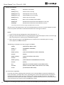
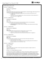
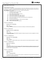
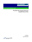
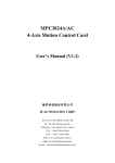
2.2 Rear Panel
L
M
A
...
.....
......
.....
...
B
....
...
.............
............
.............
............
!
K
........
.......
!
J
I
H
C
D
E
F
G
A. Motor Encoder Cable Connector
B. Motor Power Cable Connector
C. Remote CNC Cable Port
D. RS-232 Up Connector
E. RS-232 Down Connector
F. Serial Number
G. I/O Connector (Enhanced Servo Control only)
I.
Main Power Fuse
J.
Main Power Switch to Turn the Unit OFF/ON
K. Motor Cable Conduit Connection (Direct-Drive Servo Control only)
L. Air Exhaust (Direct-Drive Servo Control only)
M. Air Intake (Direct-Drive Servo Control only)
10
Hardinge Inc. One Hardinge Drive, Elmira, New York U.S.A. 14902-1507 800.843.8801 (Canada 800.468.5946) www.shophardinge.com
Part No. BB -0009500-0158
H. Power Cord (120 or 230 volt)
Servo Control User Manual B-158B
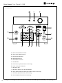
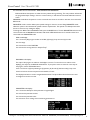
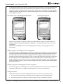
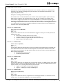
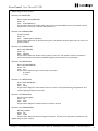
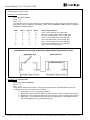
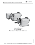
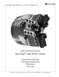
2.3 Dimensions
Standard and Enhanced Servo Control
11.1 (282)
9.6 (244)
...
.....
......
.....
...
5.98
(152)
+
!
!
....
...
9
0
.............
............
.............
............
Direct-Drive Servo Control
9.6 (244)
11.1 (282)
8.5
(216)
+
0
9
...
.....
......
.....
...
.............
............
.............
............
!
........
.......
!
....
...
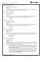
2.4 Turning ON the Servo Control
1. Verify that the power switch to the servo control is turned OFF and the power cord is unplugged.
2. Connect the encoder and power cables from the indexer to the servo control for the geared rotary indexer.
Connect the Direct-Drive rotary table if equipped with quick-connect style connector.
3. Check to verify that the red STOP button is pulled out.
4. Connect the power cord from the servo control to a 120V/15A or 230V/15A outlet.
5. Turn the power switch to the servo control ON. The display will read:
Hardinge Inc. One Hardinge Drive, Elmira, New York U.S.A. 14902-1507 800.843.8801 (Canada 800.468.5946) www.shophardinge.com
Part No. BB -0009500-0158
6. Pressing any key will allow you to continue. The panel now indicates that the axis is not homed.
The motor is now powered but the zero position is not yet defined.
11
Servo Control User Manual B-158B
7. When the indexer homes after power up, the control is looking to see the home switch and a marker
pulse on the encoder of the motor. This we will define as absolute home. A user defined home position
can be set using the procedure in step 10. If a user defined home position has been put into the control,
the indexer will show the absolute home after power up as a value other than 000.000 At this point the
zero return button must be pushed again for the indexer to position to the user defined home position. If
the previous user defined home position is no longer valid, press the clear zero set button until the control re-zeroes at the absolute home position. Now a new offset home position can be defined.
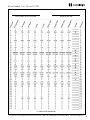
8. Jogging of the rotary indexer can now be done with the front panel JOG button. Jog the indexer in both
directions using the JOG button. The JOG button has a (+) for positive and a (–) for negative movement.
The positive and negative directions are derived from the setting of Parameter 11. The jog speed is selected with the front panel number keys and is a fraction of the maximum feed rate set by the parameters.
JOG SPEEDS:
Number pressed
Speed (% of maximum)
0
0.008
1
0.015
2
0.031
3
0.062
4
0.125
5
6
0.5
7
1.0
8
4.0
9
16.0
0.25 (default)
9. Press the ZERO RETURN button to move the rotary indexer back to the home (ZERO) position.
10. Offsetting the Zero Position
Use the left/right JOG switch to position the indexer to the position that you want to use as zero (or home)
and then press and hold the CLR key for three seconds. The display should now indicate:
POSITION 000.000
This indicates that the zero position is established and the controller is ready to begin normal operations.
If a different position is to be used as zero, jog the indexer to the new position and press the CLR key for
three seconds. The display will again indicate:
POSITION 000.000
If you had previously cleared a new home position for the indexer, the display will show a nonzero position.
In this case, press the ZERO RETURN button once more and the indexer will move forward to the predefined
zero position.
Part No. BB -0009500-0158
11. Unless otherwise stated, always press and immediately release buttons on the control. Some buttons have
more than one function depending upon which mode the servo control is in.
12
Hardinge Inc. One Hardinge Drive, Elmira, New York U.S.A. 14902-1507 800.843.8801 (Canada 800.468.5946) www.shophardinge.com
Servo Control User Manual B-158B
2.5 Three Basic Servo Control Modes - RUN, PROGRAM and PARAMETER
RUN mode allows the operator to utilize the rotary indexer during machining. The rotary indexer will execute
the programmed steps residing in the servo control memory or will execute commands via RS-232 communication.
PROGRAM mode allows the operator to insert commands into the servo control for execution once returned to
RUN mode.
PARAMETER mode is used to define system specific settings for the servo control. Using PARAMETER mode
allows the system to be customized for specific customer requirements. The operator can identify which mode
the servo control is in by reading the display.
To change from RUN mode to PROGRAM mode, press the MODE button. To enter PARAMETER mode, the servo
control must first be in PROGRAM mode. Next, hold the UP STEP SCAN button for 5 seconds and the servo
control will enter PARAMETER mode.
RUN mode display:
Line 1 shows the (PR) program number or RS-232, (N) step, (L) loop count and (G) G-code
Line 2 is empty
Line 3 shows the current POSITION
Line 4 shows the running status, for example "Stop"
PROGRAM mode display:
Two steps of the program are visible on the display at one time. To move the cursor within a screen
displaying two steps, use the DISPLAY SCAN button. To jump from screen to screen for more steps of
the program, use the STEP SCAN button.
Lines 1 and 2 show a (N) step indicating its (P) position, (G) G-code, (F) feed rate and (L) loop count
Lines 3 and 4 show the next step with its associated P, G, F and L
The Display Scan button is used to navigate between fields. The Up and Down Arrow buttons are used
to navigate from screen-to-screen.
PARAMETER mode display:
Line 1 shows the description of the parameter in logical English
Line 2 shows the parameter number
Line 3 shows the parameter value
Line 4 shows an error message if occurred during parameter set
Hardinge Inc. One Hardinge Drive, Elmira, New York U.S.A. 14902-1507 800.843.8801 (Canada 800.468.5946) www.shophardinge.com
Part No. BB -0009500-0158
13
Servo Control User Manual B-158B
3. Programming the Servo Control
The servo control has the storage capacity for 50 programs which can contain 1,000 steps each. Program 0 should
be saved for RS-232 communication. This will be covered later in the manual. The following paragraphs will guide the
operator through the programming sequence. The indexer has two basic methods of positioning: incremental and
absolute as defined below.
Absolute Positioning: Motion commands executed by the control to the indexer in absolute mode (G90) will cause
the indexer to move to the commanded or absolute position in degrees. (If you are at a position of 90.000 and the next
step in the program is 90.000 with a {G90}, the rotary will not move). The unit will rotate the shortest direction to get
to the commanded position.
Incremental Positioning: Motion commands executed by the control to the indexer in incremental mode (G91) will
cause the indexer to move an additional number of degrees from its current position. (If you are at a position of 90.000
and the next step in the program is 90.000 with a {G91}, the rotary will move an additional 90 degrees).
NOTE: Because positive 90.000 was entered, the indexer will move 90 degrees in the positive direction defined by
parameter 11.
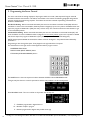
Programming is done through the square 15-key keypad on the right side of the front panel.
The three buttons on the right column of the keypad are used for program control.
MODE/RUN PROG button
DISPLAY SCAN (RIGHT ARROW) button
STEP SCAN (UP/DOWN ARROWS) button
The MODE button is the most important. It selects between the RUN mode and PROGRAM mode.
To begin, verify that the servo control is powered on and the rotary indexer is in the homed position.
Enter PROGRAM mode. The cursor will be on the position area of step one.
14
F = Feed Rate programmed in degrees/second
N = Number of steps in program
P = Position programmed in degrees with possible minus sign
Hardinge Inc. One Hardinge Drive, Elmira, New York U.S.A. 14902-1507 800.843.8801 (Canada 800.468.5946) www.shophardinge.com
Part No. BB -0009500-0158
Servo Control User Manual B-158B
G = G-code programmed using available G-code commands
L = Loop Count programmed as number of times to repeat current program step
3.1 Feed Rate (F)
The default feed rate display is 360.000 preceded by an F. This is the feed rate that will be used for the selected
step. The feed rate corresponds to degrees rotated per second. A feed rate of 360.000 means the spindle will
rotate 360 degrees in one second. See parameter 108 for alternate units. The maximum feed rate programmable
for a step is rotary indexer unit dependent. The default on the display will always read 360.000 degrees/second.
This is the standard maximum feed rate for the GD5C2 rotary indexer. This will be required to be changed if using
a rotary indexer with a smaller maximum feed rate. The GD16C2 indexer, for example, has a maximum feed rate
of 300.000 degrees per second, thus the feed rate will have to be changed for every step that will be programmed.
If the indexer being used has a higher maximum feed rate than 360.000 degrees per second, it will default to
360.000.
For example, the maximum feed rate programmable for a DD100 Rotary Table Indexer is 2700.00 degrees per
second. If a higher feed rate than 360.000 is desired with this indexer, it will have to be programmed.
Maximum Feed Rates for Hardinge Rotary Table Indexers:
Model
deg/sec (rev/minute)
GD5C2
360.000 (60 rpm)
GD16C2
300.000 (50 rpm)
GD160LP
240.000 (40 rpm)
GD210LP
240.000 (40 rpm)
DD200
1050.00 (175 rpm) at 120V, 2100.00 (350 rpm) at 230V
DD100
2700.00 (450 rpm) at 120V, 4200.00 (700 rpm) at 230V
3.2 Step (N)
The step number identifies each consecutive step in the program. Each program can store up to 1,000 steps.
Two steps of the program are visible on the display at one time. To move the cursor within a screen displaying two
steps, use the DISPLAY SCAN button. To jump from screen to screen for more steps of the program, use the STEP
SCAN button. The Display Scan button is used to navigate between fields. The Up and Down Arrow buttons are
used to navigate from screen-to-screen.
3.3 Position (P)
The position identifies the angle in degrees to be used in the step. The value can be 0 to 9999.99 depending on
the setting of parameter 12. The position value is ignored with the use of certain G-codes.
The G-code in a step of a program identifies the type of command to be executed in that step. G-codes can
command incremental or absolute positioning, dwells, jumps, clamp commands, continuous motion, etc.
The following G-codes are possible:
G28 return to home position (same as G88 and G90 with step 0)
G80 controls the clamp function when parameter 110 is set to 1 in the enhanced control
G81 controls the 3 general outputs of the enhanced control
G82 controls the 3 general inputs of the enhanced control
Hardinge Inc. One Hardinge Drive, Elmira, New York U.S.A. 14902-1507 800.843.8801 (Canada 800.468.5946) www.shophardinge.com
Part No. BB -0009500-0158
3.4 G-codes (G)
15
Servo Control User Manual B-158B
G83 continuous rotation in negative direction
G84 continuous rotation in positive direction
G85 fractional circle division (any value < or = 360.000 degrees can be divided equally)
G86 turn CNC relay ON
G87 turn CNC relay OFF
G88 return to HOME position (same as G28 and G90 with step 0)
G89 wait for remote input
(continued)
G90 absolute position command
G91 incremental position command
G92 pulse CNC relay and wait for remote input
G93 pulse CNC relay
G94 pulse CNC relay and run next L steps automatically
G95 end of subroutine/more steps follow
G96 subroutine call/jump (destination is a step number)
G97 delay by L count/10 seconds (down to 0.1 second)
G98 circle division (always assumes 360.000 degrees to be divided equally)
G99 end of program/return and end of steps
3.5 Loop Count (L)
The loop count identifies how many times a step will be repeated before moving to the next step of the program.
The loop count display is three digits between 1 and 999. If a G97 is used, the loop count is transformed to a
timer to be used as a dwell.
3.6 Inserting a Step in a Program
In program mode, put the cursor on the position area of the step which you would like to insert a step. Hold the
cycle START button for three seconds. It will cause the present step and all following steps to be moved down and
cause the new step to be initialized with default values. You will need to check and update your jump-to locations
after an insertion. The values can now be programmed for the inserted step.
3.7 Deleting a Step in a Program
In program mode, put the cursor on the position area of the step to be deleted. Hold the Zero Return button for
three seconds. It deletes the current step and will cause the next step and all following steps to be moved up by
one. You will need to check and update your jump-to locations after a step is deleted.
3.8 Selecting a Stored Program
There can be more than one stored program. Selection of that program is done by pressing the minus key while
the cursor is on the G-code area of PROGRAM mode. The display will change to: Program N
Press a number key to select a new program and then press the MODE key to return to RUN mode or the START
key to continue with the PROGRAM mode. There are fifty programs available, numbered 0 to 49.
16
To initialize or clear a stored program (not including parameters), go to PROGRAM mode and press and hold the
CLEAR-ZERO SET button for five seconds. The first step is set to G91, position value of 0, feed rate of 360.000
and a loop count of 1.
Hardinge Inc. One Hardinge Drive, Elmira, New York U.S.A. 14902-1507 800.843.8801 (Canada 800.468.5946) www.shophardinge.com
Part No. BB -0009500-0158
3.9 Clearing a Program
Servo Control User Manual B-158B
3.10 Software Limit Switch Function
The rotary indexer servo control has a feature called Software Limits. These are programmable software limits to
limit the travel in jog and run mode. Whereas the hardware limit switches are physical limit switches,
software limits are only defined in the parameters of the control. Software limits should generally be set
10 degrees less than the hardware limits. For example, if the hardware limits are set for +/- 160.000 degrees, the
software limits should be set for +/- 150.000 degrees.
Set parameter 115 to a value of 1. This will enable the use of the software limit function.
NOTE: The software limit switch function is only used AFTER initial homing is done after power-up. They provide
NO protection during the power up homing sequence. The operator needs to use caution when operating the
rotary indexer during this time to prevent damage to the unit or to the host machine tool.
Setting the positive travel limit - Parameter 116
The positive travel limit has a value range of 0 to 180000. Units are 1000 = 1 degree.
So 120.000 degrees = 120000. Jog the unit to the positive travel limit and record the value of the position.
Go into parameter mode and set the value for the high (positive) software limit.
Setting the negative travel limit - Parameter 117
The negative travel limit has a value range of 0 to -180000. Units are -1000 = -1degree.
So -120.000 degrees = -120000. Jog the unit to the negative travel limit and record the value of the position. Go
into parameter mode and set the value for the low (negative) software limit.
NOTE: It is possible to program a movement larger than the travel limit. The axis will rotate until it sees either
the negative or positive software limit and will stop. An error will be posted that the software limit has been
reached. This will require the operator to jog the axis in the opposite direction to reset the switch.
At this time, the operator should fix the limit value or change the programmed position.
You can start your program on any step by using the UP/DOWN scan keys.
4. Programming Examples
To begin, verify that the servo control is powered ON
and the rotary indexer is in the homed position.
Enter PROGRAM mode. The cursor will be on the
position area of step one.
Push the DISPLAY SCAN button to move the cursor to the G-code.
Use the number pad to select a new program number
between 1 and 49. As the buttons are pushed the
Hardinge Inc. One Hardinge Drive, Elmira, New York U.S.A. 14902-1507 800.843.8801 (Canada 800.468.5946) www.shophardinge.com
Part No. BB -0009500-0158
Push the MINUS button. The current program number will be displayed.
17
Servo Control User Manual B-158B
desired program number will appear.
Press the CYCLE START button to begin programming the new selected program. Pressing the MODE button
will change the control to the new program but send you to RUN mode. If this happens, simply re-enter
PROGRAM mode by selecting the MODE button.
Now you're ready to look at some examples.
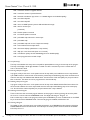
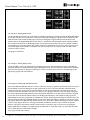
4.1 Example 1: Utilizing G91, G28 and G99
We will program the rotary indexer to perform four 90-degree moves in the positive direction, one 60-degree move in
the negative direction and return to home. A feed rate of 300 degrees per second will be used to perform the moves.
Enter the data using the numbers on the keypad, scrolling with the DISPLAY SCAN button for each screen and the
STEP SCAN button to change screens. The cursor should be on the position area of step one of the program. Enter
90000 with the keypad and then use the DISPLAY SCAN button to forward to the feed rate. If the wrong value is entered, push and immediately release the CLEAR ZERO SET button to reset and enter the correct value. Enter 300000
for the feed rate and scroll to the position area of line two.
The display should read:
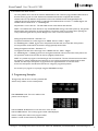
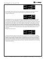
Repeat the values in step 1 for steps 2, 3 and 4 in the program. On step 5, enter -60000 for the position area and
300000 for the feed rate. On step 6, enter G28 for the G-code and 300.000 for the feed rate. For step 7, enter G99
for the G-code.
The program should read:
18
Hardinge Inc. One Hardinge Drive, Elmira, New York U.S.A. 14902-1507 800.843.8801 (Canada 800.468.5946) www.shophardinge.com
Part No. BB -0009500-0158
Servo Control User Manual B-158B
To exit PROGRAM mode, press and release the MODE/RUN PROG button. To run the program, press and release the
CYCLE START BUTTON. The indexer will rotate to 90.000 degrees and move to step 2. Press the CYCLE START
button on the control when the rotary indexer stops motion to continue through the program. After the rotary
indexer executes the G28 command in step 6 to go home, the control will reset itself to step 1 because of the G99
command in step 7. This example was the long way to perform the motions required, taking 7 steps to program. With
creative thinking and an understanding of the various G-code capabilities, programming complicated motion can be
done with fewer steps in the program. For instance, the above program could have been written with just 4 steps a
number of different ways. We will refer to example one in the following program examples to show the capability of
the G-codes.
4.2 Example 2: This example will use G28, G91 and G99 to simplify example 1 by utilizing the loop count functionality.
Change the loop count value of step one from 1 to 4. Delete steps 2, 3 and 4. To delete a step, make sure the cursor
is on position area of the step to be deleted. Press and hold the ZERO RETURN button for 3 seconds. Utilizing the
various capabilities of the control will simplify programming.
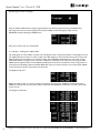
4.3 Example 3: Utilizing G90, G99 and G88
In example 1, we programmed four 90 degree moves using the incremental command of G91. Go to program mode
and change the four 90 degree angles for the four positions to absolute positions and change the G codes to G90.
Change the -60 degree move to 240.000 and make the G code G90. Finally, change the G28 to G88.
The program on the display should read:
Hardinge Inc. One Hardinge Drive, Elmira, New York U.S.A. 14902-1507 800.843.8801 (Canada 800.468.5946) www.shophardinge.com
Part No. BB -0009500-0158
19
Servo Control User Manual B-158B
4.4 Example 4: Utilizing G98 and G99
The G-code G98 can be used to do circle division to simplify programming. The G98 command will divide 360 degrees
by the value entered in the Loop Count. It is important to note that 360 degrees is always used as the angle with the
G98 command. In this example we will program 6 moves of 60 degrees using the G98 command. In step one the
Position value can be skipped. Regardless of what value is in the Position area, 360 degrees will be used. Enter G98 for
the G-code. Set the feed rate to 75.000 degrees per second. When executing step one, the rotary indexer will index
incrementally from the current position the number of degrees it calculates for each move. For the Loop Count, since
we want 60 degree moves, 360/60 = 6, therefore enter 6 in the Loop Count. For step two, make sure G99 is in the
G-code to end the program.
The program should read:
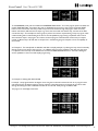
4.5 Example 5: Utilizing G85 and G99
The G-code G85 is used to do angle division to simplify programming. Whereas G98 used an angle of 360 degrees
exclusively, G85 uses an operator-entered angle for dividing the moves. The control will start the moves incrementally
from the current position. To program positioning for a series of six holes which will lie in an included angle of 180
degrees, the program will read as follows:
The G-codes G83 and G84 allow the unit to enter a continuous rotation. For geared units, the feed rate for this motion
must be limited to insure that damage to the gear system does not occur. The move should be tested and closely
monitored so that the motion does not cause the indexer to heat up and bind the gears. On direct-drive units, the
movement should be monitored so that the motor does not see a significant heat rise. In this case, liquid cooling may
have to be implemented. Utilizing this feature is therefore greatly dependent on the duty cycle. If assistance is required
to aid in the use of this function, please contact your Hardinge representative. In this example we will program the
G83 and G84 command using a feed rate of 10 degrees per second. When programming using incremental motion, the
maximum programmable step is 9999.99 degrees. In some cases where spiral milling or grinding is to be done, a longer
step may be required. The G83 and G84 commands allow this to be done. If a G83 command is given, the unit will start
a motion in the negative direction at the programmed feed rate. G84 will cause the unit to rotate in the positive
direction. This motion will continue until the control receives a command to stop. This will occur via pushing the
CYCLE START button, sending a start signal through the CNC cable or via RS-232. In step one, enter G83 and a feed
rate of 10.000. Step two should contain the G99.
The program should read as follows:
20
Hardinge Inc. One Hardinge Drive, Elmira, New York U.S.A. 14902-1507 800.843.8801 (Canada 800.468.5946) www.shophardinge.com
Part No. BB -0009500-0158
4.6 Example 6: Utilizing G83, G84, G94 and G99
Servo Control User Manual B-158B
Press cycle START and the unit will rotate in the negative direction at 10-degrees per second until the cycle start
button is pressed again to stop the motion. If motion is desired in the positive direction, enter a G84.
The program should now read:
In most applications the servo control will be commanded to move through the host machine control via the CNC
cable. See section 6.1 for remote CNC cable use. An M-code will be executed in the machine control which will
close a relay and send a start signal to the rotary indexer servo control. This will start the movement of the next step
programmed into the rotary indexer control. Usually the machine control will wait for a finish signal to come back to
the machine from the rotary indexer control to tell the machine the rotary indexer is finished and go ahead with the
part program. To use the G83 or G84 command in this fashion, a G94 will also have to be used to allow the machine
to continue. The G94 command will cause the rotary indexer servo control to immediately send a finish signal to the
machine host control and automatically execute the next number of steps determined by the value in the Loop Count.
For step one, enter G94 and 1 for the Loop Count. Step two will contain the G83 or G84 and the feed rate to be
programmed.
The program should read as follows:
Part No. BB -0009500-0158
The machine will send a start signal to the rotary indexer servo control. The servo control will issue an immediate
finish signal to the machine and perform the next step as determined by the 1 in the Loop Count. The rotary indexer
will begin a continuous rotation in the negative direction at 10 degrees per second. The machine can then bring the
tool in to do the desired operation. When the machine is finished, it will issue another start command via the M-code
which will cause the rotary indexer servo control to stop, send a finish signal and set the program to the next step. In
this case, step 3 is the G99 so the program will go back to step 1. If step 3 was another type of move or command, step
3 would be loaded ready to go.
Hardinge Inc. One Hardinge Drive, Elmira, New York U.S.A. 14902-1507 800.843.8801 (Canada 800.468.5946) www.shophardinge.com
21
Servo Control User Manual B-158B
4.7 Example 7: Utilizing spiral milling
The simultaneous rotation and milling feature of the Hardinge Servo Control will permit machining of certain cam
forms, spiral and angular cuts. Spiral milling is when the spindle rotates and an axis on your mill moves at the same time.
To spiral mill, you will have to calculate the feed rate and angle of rotation for the Hardinge rotary indexer spindle so
that the machine and rotary indexer will stop at the same instant to give the desired result.
To calculate the feed rate for the rotary indexer you will need to know:
1. The angular rotation to be performed by the rotary indexer in degrees (this should come from the print).
2. The feed rate for the axis of the mill (usually in inches per minute).
3. The distance you wish to travel on the axis on the CNC machine (this should come from the print).
For example, we wish to mill a spiral that is 6 revolutions on a part which is 12.5 inches in length. The part is oriented
on the machine to utilize the movement of the x-axis. The desired feed rate for the x-axis on the machine is 2.000
inches per minute. To set up the rotary indexer we have to calculate the angle of rotation in degrees, the cycle time in
seconds and the feed rate in degrees/second of the indexer.
The angle of rotation is calculated as follows: 6 revolutions x 360 degrees/revolution = 2160 degrees.
NOTE Parameter 12 will have to be changed to 5 to accommodate the 2160 degree move.
The cycle time is 12.5 inches/2.000 inches/minute = 6.25 minutes. Thus 6.25 minutes x 60 seconds/minute
= 375 seconds.
The feed rate of the indexer is then calculated by dividing the angle by the cycle time.
2160 degrees/375 seconds = 5.760 degrees/second.
We can now program the rotary indexer to perform the desired motion. A G94 and Loop Count of 1 will be used
in step one to start the rotary indexer and send a finish signal to the mill to start the x-axis. Thus both machine and
rotary indexer will be moving simultaneously. Step two will use the values calculated above to control the indexer to
do the spiral.
The program will read as:
This procedure will be the starting point for developing a sound program to carry out the desired task. Before
machining of the actual part, put an offset into the tooling of the machine so that it does not contact the part and
perform a dry run to determine if the program is working as desired. If possible, test the actual process on a setup part
to insure the depth of cut and speeds are not an issue. Many times, the process will involve a "rough" pass followed up
by a "finish" pass with a much smaller depth of cut. If additional spirals are to be added to the part, items such as reorientation and dwells will have to be considered and worked into the program to work out the timing.
In the same manner, a problem may exist at the end of the spiral, but this can be eliminated by slightly altering the feed
rate on the mill. Don’t adjust the feed rate on the Hardinge servo control because the mill has a much finer feed rate
adjustment than the Hardinge servo control. If the undercut appears to be in the X-axis direction, then slightly speed up
(0.1 change in feed rate) the mill’s feed rate. If the undercut appears in the radial direction of the spindle of the rotary
indexer, slow down the mill’s feed rate.
22
Hardinge Inc. One Hardinge Drive, Elmira, New York U.S.A. 14902-1507 800.843.8801 (Canada 800.468.5946) www.shophardinge.com
Part No. BB -0009500-0158
When the rotary indexer executes a G94, a 250 millisecond delay is required before executing the following step. This
may (it usually doesn’t) cause your axis to move before the table rotates, leaving a flat spot in the cut. If this is a problem, a solution is to insert a G04 dwell (from 0 to 250 milliseconds) in the CNC after the M-function to prevent axis
movement. By selecting the right dwell, the rotary indexer and the mill should start moving at the same instant.
Servo Control User Manual B-158B
If the timing is off by several seconds such that the mill completes movement before the rotary indexer completes its
movement and there are several spiral moves one right after another (such as in retracing a spiral cut), this may cause
the CNC to stop for no reason. The reason for this is that your CNC will send a cycle start signal (for next cut) to the
Hardinge servo control before it has completed its first move, thereby causing a timing hang-up. The Hardinge servo
control will not accept another cycle start until it is finished with the first. If doing multiple moves, it is very important
to check timing calculations. A way to verify if this is actually the problem is to single block the control allowing five
seconds between steps. If you can single block the control but it will not successfully run in the continuous mode, then
timing is off somewhere.
4.8 Example 8: Utilizing G95, G96, G97, G88 and G99
Subroutines allow you to repeat a particular step sequence up to 999 times. A subroutine is invoked by entering 96
into the G-code. After entering 96, you must DISPLAY SCAN to the Feed Rate location to enter the step you wish to
jump to. After executing a G96 step, the control will jump to the step called out in the Feed Rate location, execute that
step and the ones following until it reaches G-code 95 or 99, the end of subroutine call. The program then jumps back
to the step following the G96. A subroutine can be repeated a number of times by utilizing the loop count of the G96
step. To end the subroutine, insert a G-code of 95 or 99 after the last sequence step. A subroutine call is not considered a step by itself since it will always execute itself and the first step of the subroutine. Nesting of subroutine calls is
not permitted.
G97 is used to program a dwell or delay time into a program. G97 does not pulse the CNC relay at step completion.
As an example, programming a G97 and setting L = 10 will produce a 1 second dwell.
In this example, we will program the rotary indexer to perform a subroutine which will index the unit 15 degrees with
a feed rate of 300.000 then index -30 degrees with a feed rate of 25.000. Repeat the subroutine 3 times. Program a
dwell of 5 seconds. Program a G88 to return home.
The program should read as:
Part No. BB -0009500-0158
Hardinge Inc. One Hardinge Drive, Elmira, New York U.S.A. 14902-1507 800.843.8801 (Canada 800.468.5946) www.shophardinge.com
23
Servo Control User Manual B-158B
5. Features of the Enhanced Servo Control
The Enhanced Servo Control has many additional features which can be utilized by the customer. These features
include the ability to operate a clamp circuit, a cooling fan, three outputs and inputs to control extra devices, the ability
to control hardware limit switches and the addition of an E-stop circuit which can be tied to the host machine tool
control. This section will discuss in detail these added features. All of the necessary hardware to allow the function of
these additional features are located on the I/O board. The modes, programming, size and communication properties of
the Enhanced Servo Control are identical to that of the Standard Servo Control. The Enhanced Servo Control can be
identified quickly by the presence of the I/O connector on the back panel of the control.
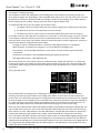
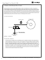
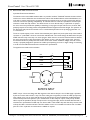
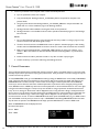
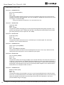
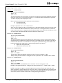
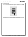
5.1 Clamp Circuit Schematic
PRESSURE SWITCH
CLAMP CYLINDER
OPEN
PORT
B
A
CLAMP VALVE
EXH EXH
IN
85 PSI IN
85 PSI Min - 110 PSI Max
REGULATOR SHOWN
FOR REFERENCE ONLY
AIR FROM MACHINE
OR SHOP
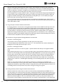
5.2 Clamp Theory of Operation
The clamp circuit is installed to work in the following way. Air is supplied to the IN port of the clamp valve at a
minimum of 85 psi and a maximum of 110 psi. The air coming out of the valve through port "B" flows through a
pressure switch and into the open port of the clamp. Therefore, if air is supplied to the unit and the power is off,
the unit is "unclamped". When power is turned on, since the valve is in the de-energized state, the unit is "unclamped". In the "unclamped" state, the pressure switch is high (ON) and sends an input to the control box verifying the status of the clamp. The valve is energized to cause the indexer to "clamp". When the valve is energized,
the output air is switched to port "A" which is plugged. This removes the air from the open port and allows it to
exhaust. The pressure switch goes low (OFF) because of the lack of air pressure. This removes the input to the
control box and the software considers the unit "clamped".
Part No. BB -0009500-0158
24
Hardinge Inc. One Hardinge Drive, Elmira, New York U.S.A. 14902-1507 800.843.8801 (Canada 800.468.5946) www.shophardinge.com
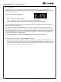
Servo Control User Manual B-158B
Manual Switch (Blue)
A
B
IN
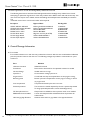
5.3 Clamp Functionality of the Enhanced Servo Control
The clamp circuit is designed for a normally open valve which allows the clamp on the rotary indexer to be in
an unclamped state when air is supplied to the rotary indexer. An air hose connector is provided either on the
motor cover or the back of the Enhanced Servo Control to supply the air to the clamp circuit. When the unit
is shipped from the factory, this connector is identified with a red tag. An air hose is also supplied with the unit
to be used to route the air supply from the rotary indexer to the outside air supply from the facility. The installation of the air line is machine specific. It should be routed so that it will not become tangled with any part of the
machine during normal operation. Hardinge will not be responsible for damage to any utilities which were not
installed at the factory. A minimum air supply of 85 psi is required for the clamp circuit to function properly. The
clamp circuit consists of three basic components. These are the clamp, pneumatic valve and pressure switch. The
clamp is a failsafe device meaning that if air is removed from the device it will cause the clamp to engage which will
prevent the rotary indexer from motion. This is why a verified presence of 85 psi of air must be supplied to the
clamp prior to operation of the rotary indexer. The pneumatic valve is a normally open 24 V valve. In this circuit,
the clamp is engaged when the solenoid of the valve is energized and disengaged when the solenoid is de-energized. Finally, there is an electronic pressure switch installed in the circuit to monitor the clamp when it is disengaged. The clamp functionality will take place after initial homing after power up. No clamp functionality is applied
before that. When the clamp is engaged, a "C" will appear on the message line of the control display.
There are two Parameters which control the operation of the clamp circuit – parameters 110 and 111.
0 = Clamp is ignored – if a clamp is physically on the unit, shop air still has to be supplied
1 = G-code commands the engage/disengage of the clamp
2 = Automatic clamp control – clamp is automatically engaged when motion is stopped
Parameter 111 is a timer for the clamp function dwell. It can have a value of 0 - 2000. The units of this value are
in milliseconds. If the value of parameter 110 is equal to 0, then parameter 111 should be set to a value of 0. If the
value of parameter 110 is equal to 1 or 2, then the value of parameter 111 should be set to 350 or greater. The
timer is utilized when the rotary indexer starts and stops. Prior to motion, the clamp will disengage and the timer
will count down. When motion stops, the dwell will count down and the clamp will engage.
Hardinge Inc. One Hardinge Drive, Elmira, New York U.S.A. 14902-1507 800.843.8801 (Canada 800.468.5946) www.shophardinge.com
Part No. BB -0009500-0158
Parameter 110 defines the mode of the clamp circuit. The possible values of this parameter and their
definitions are:
25
Servo Control User Manual B-158B
The clamp takes approximately 0.5 seconds to engage and 0.5 seconds to disengage. Along with that time, the
dwell would be added to obtain a total cycle time for engaging and disengaging the clamp. When programming the
Enhanced Servo Control when a clamp is present, there are no additional steps involved when parameter 110 =
0 or 2. Some machining processes may not require the use of the clamp. If this is the case, parameter 110 can be
set to a value of 1. This will reduce the cycle time of the process by only using the clamp for required machining.
If parameter 110 is equal to 1, G80 is used to program the operation of the clamp circuit. Using G80 will work as
follows:
To engage the clamp: G80 has to be used for the G-code and the feed rate must be set to 1.111.
To disengage the clamp: G80 is used and the feed rate must be set to 0.
The two steps in the program would read as follows:
Step one of the program engages the clamp and step two disengages the clamp
5.4 Tips for Clamp Use
1.
If the error message "FLT Clamp Pressure Low" appears on the control display, the clamp function is turned
on but the pressure switch is not being satisfied. If a clamp is installed on the unit, insure that the shop air
is at 85 psi and connected to the unit. If it is determined that the shop air is connected properly and the air
pressure is sufficient, contact a Hardinge technician immediately for help related to this issue. If a clamp is not
installed on the unit, parameter 110 is set wrong. Change parameter 110 to 0.
2.
When aligning a fixture with parameter 110 set to 2, it is difficult to jog the rotary indexer at low speeds to
fine tune the alignment. If this is the case, change parameter 110 to 0 and align the fixture. After the alignment
is complete and the desired zero is set, change parameter 110 back to 2.
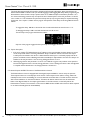
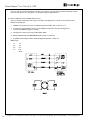
5.5 General Purpose OUTPUT Functions of the Enhanced Servo Control
The Enhanced Servo Control is equipped with three digital outputs available for custom use by the operator.
These outputs function as a normally open set of contacts. These outputs can be useful in running valves automatically for items such as workholding for trunnions, tailstocks and collet closers. The I/O connector has three
24V sources available to run the external devices. Therefore, the devices need to be 2-wire, 24 volt devices.
Refer to the diagram below for the output signal locations on the I/O connector on the back panel of the
Enhanced Servo Control. The connector on the control is DB15 female. A DB15 male connector will be required
to use this functionality (Part No. CI 001024201).
Part No. BB -0009500-0158
26
Hardinge Inc. One Hardinge Drive, Elmira, New York U.S.A. 14902-1507 800.843.8801 (Canada 800.468.5946) www.shophardinge.com
Servo Control User Manual B-158B
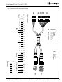
AUX I/O CONNECTOR ON BACK
OF ENHANCED SERVO CONTROL
E-STOP GROUND
24 V
OUTPUT 3
E-STOP SIGNAL
GROUND
INPUT 2
OUTPUT 2
INPUT 3
OUTPUT 1
INPUT 1
24 V
24 V
GROUND
Output 1 is pin 15
Output 2 is pin 8
Output 3 is pin 7
Pins 6, 13 and 14 are available 24V sources
GROUND
GROUND
To program the outputs, G81 is used in the step of the part program. The position value of the step will identify
which output to be used. The feed rate value will determine whether the output is being turned on or off.
In the position area, when selecting which output to use, the definitions are as follows:
Output 1 = 1.000
Output 2 = 2.000
Output 3 = 3.000
In the feed rate area, 1.111 will turn the output on and 0 will turn the output off.
Programming Example of Output Function:
To turn on output 1 and to turn off output 1 would appear as follows in program mode:
Step one is turning on the output and step two is turning off the output.
If the servo control is being started externally via an M-code and the machine control requires a finish signal, the
following programming procedure can be used to turn the outputs on and off.
Hardinge Inc. One Hardinge Drive, Elmira, New York U.S.A. 14902-1507 800.843.8801 (Canada 800.468.5946) www.shophardinge.com
Part No. BB -0009500-0158
NOTE: When the output functions are used in the steps of a program, it is important to note that a finish signal
will not be sent by the servo control when a G81 step is completed. This means that when an output is turned
ON or OFF, a finish signal will not be sent to the machine host control. To utilize this function when using an
M-code that requires a finish signal, programming of these functions will have to utilize the G94 command to send
back the finish signal to the machine control to allow the machine process to proceed. If the machine host control
does not require a finish signal, the use of the outputs can be used as outlined above.
27
Servo Control User Manual B-158B
In the above photographs, step one and two will turn on output 1. Step one will send the machine host control the
required finish signal. When the next M-code is sent to the rotary indexer servo control, steps three and four will
turn off output 1. Step three will send the machine control the required finish signal.
The use of the outputs can be programmed and commanded using the RS-232 function. Follow the programming
procedure outlined in the RS-232 section of the manual. The G-code will be G81, the feed rate will be 1.111 or 0
and the position value will be 1.000, 2.000 or 3.000.
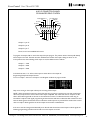
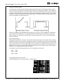
5.6 General Purpose INPUT Functions of the Enhanced Servo Control
The enhanced servo control box is equipped with three digital inputs available for custom use by the operator.
The inputs can be configured to be normally open circuits or normally closed circuits. See parameter 112 for the
definition of the status of the inputs. The inputs can be used to monitor safety switches used to check the status
of devices using the control box outputs. They can also be configured to use hardware limit switches for applications when the travel of the indexer is restricted because of clearance issues. Parameter 113 defines the definition
of the outputs when using them with hardware limit switches.
Refer to the diagram below for the input signal locations on the I/O connector on the back panel of the
Enhanced Servo Control.
AUX I/O CONNECTOR ON BACK
OF ENHANCED SERVO CONTROL
E-STOP GROUND
24 V
OUTPUT 3
OUTPUT 2
INPUT 3
OUTPUT 1
INPUT 1
24 V
GROUND
Input 1 is pin 9
Input 2 is pin 2
Input 3 is pin 1
Pins 3, 10, 11 and 12 are available grounds
GROUND
GROUND
Hardinge Inc. One Hardinge Drive, Elmira, New York U.S.A. 14902-1507 800.843.8801 (Canada 800.468.5946) www.shophardinge.com
Part No. BB -0009500-0158
24 V
28
E-STOP SIGNAL
GROUND
INPUT 2
Servo Control User Manual B-158B
The logic of the input software
In the control box, the input function can be used and programmed to monitor system devices. When using the
input commands in a part program, the condition which the control is looking to be satisfied is a true condition to
continue to the next program step. If the input condition is false, the program will hang on the input step until the
condition is made to be true. The condition for which the input is looking for is set by Parameter 112 (see parameter section of manual for definitions). In the parameter section, a value of 0 identifies a normally open circuit and
a value of 1 identifies a normally closed circuit.
There are many different devices available that the operator may choose to use in the application. These devices
can be chosen to be normally open or normally closed devices. Sometimes they are referred to as sourcing or
sinking. Therefore, it is important to have the inputs correctly set by parameter 112 to work with the hardware
device to be utilized
Programming the Inputs
To program the inputs, G82 is used as the G-code in the step of the part program. The position value of the step
will identify which input to be monitored. The feedrate values for this function are ignored. As with outputs (G81),
the step of a program which utilizes an input (G82) function will not generate a finish signal from the control. The
program will not continue in the rotary table indexer control until the input is satisfied. In this example, make sure
parameter 112 is set to 0. This means that all inputs are normally open. Have a jumper ready to test the logic of
the input circuit. To begin the test, no jumper is required.
In the position area, when selecting which input to use, the definitions are as follows:
Input 1 = 1.000
Input 2 = 2.000
Input 3 = 3.000
Programming Example of Input Function
In the following photo, the monitoring of input 1 is demonstrated:
Hardinge Inc. One Hardinge Drive, Elmira, New York U.S.A. 14902-1507 800.843.8801 (Canada 800.468.5946) www.shophardinge.com
Part No. BB -0009500-0158
29
Servo Control User Manual B-158B
Step two of the program will check for the status of input 1 when executed. The software will not allow the
program to continue until the condition of input 1 is satisfied (true). Once input 1 is satisfied, the program will
advance to step three. If the input is configured to be normally closed, it will wait for the circuit to be closed. If
the input is configured to be normally open, it will wait for the circuit to be open.
Run the program with no jumper in place for input 1, the program should continue through step two. Repeat the
program with the jumper installed between pin 9 (input 1) and pin 3 (ground) on the I/O connector. When the
program is executed, it will hang on step two because the normally open input 1 is now closed by the jumper.
Remove the jumper and the program will move to step three.
The use of the input function can be programmed and commanded using the RS-232 function. Follow the programming procedure outlined in the RS-232 section of the manual. The G code will be G82 and the position value
will be 1.000, 2.000 or 3.000.
5.7 Using the Inputs to Monitor Hardware Limit Switches
By changing parameter 113, the function of the general purpose inputs can be modified so that they can be used
to monitor hardware limit switches. See the definitions of this option in the parameter section of the manual.
Using these inputs for hardware limit switches can be valuable when there is a potential for damage to occur to
the rotary indexer or machine tool when the travel of the rotary indexer should be limited. This is especially
helpful in the homing procedure after power up in preventing travel into a restricted area. This is a backup to the
software limits which are only valid after initial power up and homing. With the optional Hardinge limit switch kit,
hardware limits are adjustable to meet most operator applications.
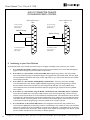
5.8 Procedure for Using the Optional Hardinge Hardware Limit Switch Kit
Parameter 112 Inverse Dig Input
This parameter inverts the input signal between normally open and normally closed.
To use the hardware limit switches this must be set to 3 or 7. This is because the limit switches utilized by the
Hardinge Kit are normally open and use inputs 1 and 2.
Parameter 113 Set Dig Input Mode
This parameter must be set to a value of 3 (Input 1 is positive hardware limit and input 2 is negative hardware
limit).
When operating the system in jog or run mode, if a hardware limit is encountered there will be an error message
posted on the control display which reads "HW LIMIT JOG OPP DIRECTION". This will require the operator to
press the green cycle start key one time to clear the error message. Then the operator must jog the indexer in
the opposite direction to the "safe area". The rotary indexer will only be able to rotate in the "safe direction".
The hardware limit switches are located on the back of the indexer under a sheet metal cover. They have been
adjusted to have a travel of +/- 160.000 degrees. Depending on the workholding and part size, these may have to
be adjusted.
NOTE: It is very important that the rotary indexer is homed prior to mounting any workholding on the
system. Once homed, you can then jog the rotary indexer in the positive and negative directions to determine the
available travel. If needed, re-adjust the limit switches to safely operate the system. Once adjusted correctly to the
workholding limitation, this will provide security when homing and running part programs.
30
With the hardware limit switch function turned on and the switches properly adjusted, press ZERO return on
the rotary indexer servo control. If the axis encounters a hardware limit switch, the control will stop the axis and
require the operator to jog the axis in the opposite direction. Hold the jog button until the axis homes. If needed,
press the 5 key on the keypad to jog faster. During the homing operation, only the hardware limit switches are
effective for protection against a crash. The rotary indexer homes on power up in the positive direction. The
home position is when the B-axis is vertical. If the A-axis is in a position in which the B-axis is on the positive side
Hardinge Inc. One Hardinge Drive, Elmira, New York U.S.A. 14902-1507 800.843.8801 (Canada 800.468.5946) www.shophardinge.com
Part No. BB -0009500-0158
5.9 Homing the Rotary Indexer Using the Hardware Limit Switch Kit
Servo Control User Manual B-158B
of home, the A-axis will trip the positive hardware limit switch when trying to home. This will require the operator to jog back in the negative direction to find home. If the B-axis is on the negative side of home, the A-axis will
home directly to the home position. Once the home position is established on power-up, the rotary indexer will
take the shortest path to home until power is shut off to the control. After initial homing is done, the software
limit switches will become active and be used. See the section of the manual defining the software limit switch
function.
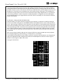
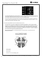
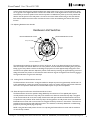
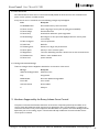
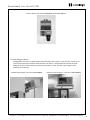
5.10 Adjusting Hardware Limit Switches
Hardware Limit Switches
POSITIVE HARDWARE LIMIT SWITCH
POSITIVE HARDWARE LIMIT SWITCH
M5 ADJUSTING SCREWS
POSITIVE
TRAVEL
NEGATIVE
TRAVEL
LIMIT SWITCH REFERENCE DOG
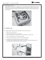
The hardware limit switches are located on the rear of the unit. A rear cover plate will need to be removed to
observe and adjust the switches. Make sure the rotary indexer is homed. Install the workholding and a part piece.
Slowly jog the rotary indexer until the workholding and part piece are within approximately 10 degrees of their
travel limit in the positive direction. Adjust the positive travel switch by loosening the (2) M5 adjusting screws and
sliding the bracket into position to sense the limit switch reference dog. Set the negative travel switch by jogging in
the negative direction using the same technique.
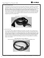
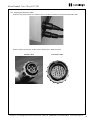
5.11 Cooling Fan for the Enhanced Servo Control
The Enhanced Servo Control has a cooling fan installed to dissipate any extra heat generated by the I/O board. It
is also responsible for cooling the control when the bigger motors are used for the larger geared units and directdrive units. The operation of this feature is automatic and requires no input from the operator.
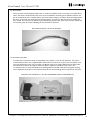
The Enhanced Servo Control is capable of being disabled by the machine tool. This capability will require a
normally closed contact from the E-stop relay in the machine tool. When the machine E-stop relay is energized
on the machine side of the circuit, the normally closed contact will open and allow the Enhanced Servo Control
to operate the rotary indexer. When the E-stop relay is de-energized, the normally closed contact will disable the
Enhanced Servo Control until corrective action re-energizes the E-stop contactor in the machine. There are two
possible hookups (shown) that will enable this function. This interlock can be easily disabled for troubleshooting
purposes by removing the I/O plug temporarily.
NOTE: Using this feature will prevent the user from operating the Enhanced Servo Control until the machine is
out of its E-stop condition.
Hardinge Inc. One Hardinge Drive, Elmira, New York U.S.A. 14902-1507 800.843.8801 (Canada 800.468.5946) www.shophardinge.com
Part No. BB -0009500-0158
5.12 External Stop Circuit Function of the Enhanced Servo Control
31
Servo Control User Manual B-158B
AUX I/O CONNECTOR ON BACK
OF ENHANCED SERVO CONTROL
Enhanced I/O Connector
DB15
for top connect
use 6, 13 or 14
(all 24 volts)
Enhanced I/O Connector
DB15
for top connect
use 6, 13 or 14
(all 24 volts)
Machine E-stop
Machine E-stop
for bottom connect
use 3, 10 or 11
(all 0 volts)
for bottom connect
use 3, 10 or 11
(all 0 volts)
6. Interfacing to your Host Machine
As mentioned earlier in this manual, there are five ways to configure a Hardinge rotary product to your machine:
1. As a stand-alone unit with a control. Programming is done in the indexer servo control and executing the
program is done through the cycle start button on the control.
2. As an add-on to a host machine via the remote CNC cable. Programming is done in the rotary indexer
servo control and the program is executed through a start signal via the remote CNC cable. This start signal
can be provided by a mechanical switch (the remote quill switch) or by a relay contact from the host machine
control using an M-code.
3. As an add-on to a host machine utilizing RS-232 communication. The servo control has the ability
to communicate with a host machine capable of RS-232 programming commands. Programming is done in
the host machine control and commands are sent through the RS-232 cable. The rotary indexer servo
control interprets these commands and executes them. No programming is required in the rotary indexer
servo control.
5. As a true 4th-axis to the machine CNC control. This configuration removes the rotary indexer servo
control from the application and the rotary product is wired directly to the machine. A rotary unit purchased
with a servo control may not be convertible to a true 4th-axis configuration. A compatible motor to the host
machine is required at time of purchase. When using the rotary product wired directly to the machine, consult
the host machine manufacturer for information on 4th-axis operation.
32
Hardinge Inc. One Hardinge Drive, Elmira, New York U.S.A. 14902-1507 800.843.8801 (Canada 800.468.5946) www.shophardinge.com
Part No. BB -0009500-0158
4. As an add-on to a host machine using the RS-232 communication and remote CNC cable in conjunction.
This is the most reliable use of the rotary indexer with the servo control. Programming is done in the host
machine control and commands are communicated over the RS-232 cable. The machine then uses an M-code
to send the start signal through the remote CNC cable and the rotary indexer servo control will execute the
commanded motion. The rotary indexer servo control then sends a finish signal to the host machine control
to cancel the M-code. No programming in the rotary indexer servo control is required.
Servo Control User Manual B-158B
6.1 Remote CNC Cable Connection and Use
Cycle Start/Finish Circuit Definition
The function of the remote CNC interface cable is to provide a hardware "handshake" between the main machine
and the servo control. While the control will function without this handshake feature, as described elsewhere, it is
much safer to use this simple 4-wire connection between the machine and servo control to prevent the machine
and servo control from operating independently. To make this feature as universal as possible, the interface implementation is made with relay contacts. This allows the user to use an M-code relay or a quill switch to operate
the servo control and provides the capability of interfacing to many types of inputs with the servo control’s "FIN"
(finished) response. It also helps prevent incompatibilities between equipment interface voltages. The operation of
the "FIN" signal relay can also be inverted to act as a machine feed permissive circuit by changing parameter 2 to
a 1 instead of a 0.
The servo control expects to see a contact closure between pins 3 (black wire) and 4 (white wire) of the interface
connector to "cycle START" the servo control when in RUN mode. The control settings will determine if the cycle
START executes a loop count, step or an entire program. When the servo control has executed what was desired,
the servo control closes a relay contact back to the machine on pins 1 (red wire) and 2 (green wire). It should
be noted that while every attempt has been made to work with a number of different voltages, the "FIN" contact
circuitry is purposely designed to operate a 24 volt DC input. Operating at a lower or higher voltage or interfacing
to an AC circuit should be discussed with a manufacturer’s representative.
The typical 4 wire interface is shown below.
1
RED
2
GREEN
INPUT
FIN
+24 V DC
3
BLACK
START
+12 V
4
WHITE
R206
ISO100
680
SERVO CONTROL
MACHINE
START
4
1
FIN
2
3
PINOUT
NOTE: On pin 1 the circuit voltage 24 V DC originates in the machine. On pin 3 the 12 V DC supply is provided
by the servo control and is fused at 1 amp. The color codes given are typical. If you hook the cable up and put any
other voltage on pin 3 or pin 4, the internal fuse may be shorted out, the opto-isolated input could be damaged,
and the fuse may need to be replaced. If your machine does not have relays for outputs, a relay kit may be available. It may also be possible to directly drive pin 4 with a sourcing DC output, but this should be discussed with a
manufacturer’s representative. The FIN relay is an Omron G2R-1 12vdc S.P.D.T. relay with silver alloy contacts rated
at 5amps 30 V DC. It is de-bounced with a 24 V DC snubber circuit. It is not suitable for loads less than 10 milliamperes at 5 F DC. A pdf with more information is available on request.
Hardinge Inc. One Hardinge Drive, Elmira, New York U.S.A. 14902-1507 800.843.8801 (Canada 800.468.5946) www.shophardinge.com
Part No. BB -0009500-0158
REMOTE INPUT
33
Servo Control User Manual B-158B
NOTE: Make sure your CNC has the same number of M-functions programmed as you have steps in the
Hardinge servo control. Do not program two M-functions, one directly after another, in your CNC control
to index the Hardinge servo control. This may cause a timing hang up in your CNC. Use a dwell between
them in the CNC control. See setting of parameter 31 and program the equivalent dwell.
6.2 RS-232 Capabilities
The Hardinge Servo control has the capability of RS-232 communication for running commands and uploading/
downloading programs. There are two connectors on the back panel of the control for connecting RS-232 cables.
The top connector (RS-232 UP) is used for commanding and transferring programs. The bottom connector (RS232 DOWN) is used for connecting servo controls together. This is called daisy chaining. Up to nine controls can
be daisy-chained together.
To use a PC to communicate with the rotary indexer servo control, an RS-232 cable is required. This cable will
require the DB-25 pin male connector on one end and either a USB or DB-9 connector for the PC. The cable
used must be wired DTE (Data Terminal Equipment) on the PC end. Next the PC and rotary indexer control must
be configured to perform the communication. HyperTerminal is common on most PCs and will serve as the tool
to accomplish the task.
The following parameters should be set in the servo control to the appropriate value.
Parameter 21 = 4 (X-axis)
Parameter 26 = 7 (baud rate = 9600)
Parameter 105 = 1 (stop bits = 1)
Parameter 106 = 8 (data bits = 8)
Parameter 107 = 0 (no parity checking)
6.2.1 Configuring the PC using HyperTerminal
Part No. BB -0009500-0158
1. Use the HyperTerminal application for uploading/downloading programs to the rotary indexer. The HyperTerminal application is available in every Windows operating system. Launch HyperTerminal from the START
menu Programs/Accessories/Communication/HyperTerminal.
34
Hardinge Inc. One Hardinge Drive, Elmira, New York U.S.A. 14902-1507 800.843.8801 (Canada 800.468.5946) www.shophardinge.com
Servo Control User Manual B-158B
2.
Enter connection name (Hardinge for example) and click enter.
3.
In the "Connect Using" option select the COM port to be used for communication.
Part No. BB -0009500-0158
Hardinge Inc. One Hardinge Drive, Elmira, New York U.S.A. 14902-1507 800.843.8801 (Canada 800.468.5946) www.shophardinge.com
35
Servo Control User Manual B-158B
4. Define COM port properties:
"Bit per second" is an RS232 communication baud rate. This field should be set according to rotary indexer
parameter 26. (E.g. if parameter 26 is 7, baud rate 9600 should be selected)
"Data bits" - select 8
"Parity" - select None
"Stop bits" - select 1
"Flow control" - select None
Click OK
Part No. BB -0009500-0158
36
Hardinge Inc. One Hardinge Drive, Elmira, New York U.S.A. 14902-1507 800.843.8801 (Canada 800.468.5946) www.shophardinge.com
Servo Control User Manual B-158B
5. In the HyperTerminal menu, select File/Properties. "Hardinge properties" window will be open. Select
"Settings" tab and click on "ASCII Setup".
In "ASCII setup" window, set "Line delay" to 10, "Character delay" to 1. Select Echo type characters locally.
Click OK.
Click OK to exit properties.
6.2.2 Uploading and Downloading Programs using a PC
1.
Make sure HyperTerminal is open and communicating with the rotary indexer Servo Control.
2.
Enter Program Mode on the rotary indexer Servo Control.
3.
Activate the program to be uploaded.
4.
Position the cursor on the G-code of step one.
5.
Press the (–) button on the keypad.
6.
Press the (–) button again on the keypad. Display should now read: Send prog: #
7.
In HyperTerminal, select Transfer/Capture text.
8.
A dialogue box will appear asking for the file to be named and saved. Select location, name file and press start.
9.
Press the Cycle Start button on the rotary indexer Servo Control. Program will start uploading. A message
"sending program " will appear. Once the message disappears, it is complete. In HyperTerminal, the program
will be displayed on the computer screen.
10. In HyperTerminal, select transfer/capture text/stop.
Hardinge Inc. One Hardinge Drive, Elmira, New York U.S.A. 14902-1507 800.843.8801 (Canada 800.468.5946) www.shophardinge.com
Part No. BB -0009500-0158
UPLOADING – Transfer programs from the Servo Control to the computer.
37
Servo Control User Manual B-158B
11. The program has been uploaded and can be opened and edited with notepad.
12. Close HyperTerminal.
13. Exit Program Mode in the rotary indexer Servo Control.
DOWNLOADING – Transfer programs from the computer to the servo control.
1.
Make sure HyperTerminal is open and communicating with the rotary indexer Servo Control.
2.
Enter Program Mode on the rotary indexer Servo Control.
3.
Activate the Program number where you wish to save the downloaded file.
4.
Position the cursor on the G-code of step one.
5.
Press the (–) button on the keypad.
6.
Press the (–) button again on the keypad.
7.
Press the (–) button a third time on the keypad. The display should now read: Receiving prog: #
8.
In HyperTerminal, select transfer/send text file. A dialogue box will appear to select the file. Do not select yet.
Leave dialogue box active and move to the rotary indexer Servo Control.
9.
On the rotary indexer Servo Control, press Cycle Start. A message "Receiving program " will appear.
10. In HyperTerminal, select the program file using the dialogue box and press Open.
11. The program will be downloaded and displayed on the rotary indexer Servo Control when complete.
12. Check the steps of the program to insure that the transfer worked correctly.
13. Correct any errors manually that may have occurred in the program of the rotary indexer Servo Control.
14. The program is now ready for use in the rotary indexer Servo Control.
15. Close HyperTerminal.
16. Exit Program Mode in the rotary indexer Servo Control.
Programming Format for Uploading/Downloading Programs
When downloading a program to the indexer servo control, the first and last steps of the program should be the
% symbol. When programs are uploaded from the control to the PC, this is automatically completed.
For example:
%
N001 G91 S090.000 F080.000 L001
N002 G91 S-060.000 F100.000 L001
N003 G99
%
38
A PC can be used to send commands to the rotary indexer Servo Control via RS-232. The rotary indexer will
translate these commands and execute the desired functions. This is particularly helpful for custom applications
utilizing a PC-based control system. When using this function of the rotary indexer Servo Control, HyperTerminal can be used for controlling the rotary indexer. Other programs may apply but this manual will outline using
HyperTerminal. It is important that the HyperTerminal function be configured as described above. Be sure capslock is on when typing the commands in HyperTerminal.
Hardinge Inc. One Hardinge Drive, Elmira, New York U.S.A. 14902-1507 800.843.8801 (Canada 800.468.5946) www.shophardinge.com
Part No. BB -0009500-0158
6.2.3 Using a PC to Send Commands to the rotary indexer Servo Control
Servo Control User Manual B-158B
The following are the RS-232 commands, where "x" is the selected Axis and "n" is the Value:
CommandMeaning
xSn.nnn
Specifies a step size or absolute position. Step size can be negative or positive.
xFn.nnn
Specifies the Feed Rate in units/second.
xGnn
Specifies the G-code to be used.
xLnnn
Specifies the Loop Count to be used.
xP
Will show the rotary indexer's current position.
xB
Begin the programmed step on the "x" axis only.
B
Begin the programmed step on ALL axes at once.
xH
Return to the Home position.
xC
Clear the servo Position and set to zero.
xO
Turn on the servo.
xE
Turn off the servo.
xSTOP Stop the rotary indexer.
x J
Jog the indexer. Units are encoder counts/second. Can be negative or positive.
There must be a space between the capital "J" and the number.
NOTE: Above where an "n" decimal value is possible, at least one digit to the right of the decimal point has to be
entered. For example, "xS90." will not work, it must be "xS90.0".
Programming Example:
Program the rotary indexer Servo Control to make a 90 degree move at 30 degrees/second incrementally using
the PC and RS-232 communication. The axis identifier will be A (parameter 21 = 7).
In HyperTerminal type:
AS90.000 [Enter]
Programs an angle of 90 degrees
AF30.000 [Enter]
Programs a feed rate of 30 degrees/second
AG91
[Enter]
Programs a G91 for incremental motion
AB
[Enter]
Sends a start command to the A axis
Once a command is sent to the rotary indexer Servo Control, it will remember the command until it is changed.
Therefore, to repeat a move, simply send nB to the control again.
If a situation exists where more than one rotary indexer with servo control is placed on a machine tool, it is
possible to communicate with the rotary indexer Servo Controls and the machine tool control using RS-232. This
is accomplished by connecting RS-232 cables from one control to the next. To accomplish this, a DB25 male to
DB25 female cable is required. One Servo Control, which will serve as the master, will connect to the machine tool
host control as normal. A second RS-232 cable will run from the master rotary indexer Servo Control DOWN
port to the next indexer Servo Control UP port. This is called daisy chaining. Up to nine controls may be daisychained together. When programming the machine tool control, it is important that the axis identifier preceding
a command is properly addressed. Each rotary indexer Servo Control should be set up as a different axis using
parameter 21. See parameter 21 definition for the available labels. It is also important to note that the axis identifier be used before a B command, i.e. XB, AB, etc. If only B is programmed, all axes will move at the same time.
Hardinge Inc. One Hardinge Drive, Elmira, New York U.S.A. 14902-1507 800.843.8801 (Canada 800.468.5946) www.shophardinge.com
Part No. BB -0009500-0158
6.2.4 Multiple controls utilizing RS-232 (Daisy Chaining)
39
Servo Control User Manual B-158B
If you are only using one of the boxes in the chain, it is necessary to power up all of the boxes between the data
source and the box you are using. Data is not passed through an unpowered box.
6.3 Remote Operation with a FANUC CNC Control
There are several requirements that must be met before a Hardinge Servo Control can be interfaced with a
FANUC-controlled mill.
1. FANUC control with custom macro enabled and parameter 6001, bits 1 and 4 set to "1".
2. A serial port on the FANUC control must be available for exclusive use by the Hardinge Servo
Control while DPRNT program is running.
3. Hardinge Servo Control and rotary table indexer UNIT.
4. RS-232 shielded cable 25' DB25M/DB25M (null modem not required)
5. A shielded remote CNC interface cable Hardinge Part Number: CI-3011-IC
DB25 pinout:
Part No. BB -0009500-0158
1-1 2-2
3-3 4-4
5-5 6-6
7-7 8-8
20-20
40
Hardinge Inc. One Hardinge Drive, Elmira, New York U.S.A. 14902-1507 800.843.8801 (Canada 800.468.5946) www.shophardinge.com
HARDINGE SERVO CONTROL Parameters for RS-232 Interface
Once the previous requirements have been met, you can revise the parameters of the Hardinge control. Listed
below are the parameters that will need to be changed.
Parameter 1 = 1
Parameter 2 = 0
Parameter 5 = 0
Parameter 8 = 0
Parameter 10 = 0
Parameter 12 = 5 or 6
Parameter 21 = 4* (see table 1)
Parameter 26 = 5* (see table 2)
Parameter 31 = 0
Parameter 105 = 2
Parameter 106 = 8
Parameter 107 = 0
Table 1:
Table 2:
0 = upload/download programs 1 = U
0 = 110
1 = 300
2 = V
3 = W
2 = 600
3=1200
4 = X
5 = Y
4 = 2400
5 = 4800
6 = Z
7 = A
6 = 7200
7 = 9600
8 = B
9 = C
8=19200
FANUC CNC CONTROL Parameters for RS-232 Interface
The FANUC control parameters are usually set as follows to successfully communicate with the Hardinge Servo
Control.
Baud Rate
4800*
Parity Even
(Required setting, do not experiment)
Data Bits
7 or ISO (if CNC control defines Data bits as work length + parity bit, then set to 8)
Stop bits
2 (Required setting, do not experiment)
Character Coding (EIA/ISO)
ISO (Required setting, EIA will not work)
DPRNT EOB
LF CR CR (CR is required, LF is always ignored by Servo control)
DPRNT leading zeroes as blanks OFF
*Initial settings. Experiment with these settings only AFTER interface is functional.
Be certain to set FANUC parameter related to actual serial port connected to Hardinge Servo Control.
The parameters have been set for remote operation. You can now program or run an existing program.
There are several key items you need to consider to insure your program will run successfully. First and foremost
DPRNT must proceed every command sent to the Hardinge Control. The commands are sent to the control in
ASCII code and terminated by a carriage return (CR.). All commands must be preceeded by an axis select code (U,
V, W, X, Y, Z), parameter 21 = 4. For this explanation, X will represent the axis code.
Hardinge Inc. One Hardinge Drive, Elmira, New York U.S.A. 14902-1507 800.843.8801 (Canada 800.468.5946) www.shophardinge.com
Part No. BB -0009500-0158
Servo Control User Manual B-158B
41
Servo Control User Manual B-158B
RS 232 Command Blocks
DPRNT[ ]
Clear/Reset receive buffer
DPRNT[XGnn]
Loads G-code nn into Step
DPRNT[XSnn.nnn]
Loads Step Size nnn.nnn into Step
DPRNT[XFnn.nnn]
Loads Feed Rate nnn.nnn into Step
DPRNT[XLnnn]
Loads Loop Count into Step*
DPRNT[XH]
Return home immediately without M-FIN
DPRNT[XB]
Activates Remote Cycle Start without M-FIN for X-axis only*
DPRNT[B]
Activates Remote Cycle Start without M-FIN for all axes*
*Initial settings. Experiment with these settings only AFTER interface is functional.
Only one step can be programmed at a time over the RS-232 interface to the servo control. If multiple commands
are sent, only the last sent codes are retained and executed when a start signal is received.
NOTES:
1
Use of "X" above assumes Hardinge Servo Control Parameter 21 = 4.
2. Trailing "0" must be included when not using a decimal point. If using a decimal point, at least one numeric digit
after the decimal point is required. (Correct: S045.000, Wrong: S45)
3. When writing your program in the FANUC format, it is important not to have blank spaces or carriage
returns (CR) in your DPRNT statement.
The following is an Example of one way to program the FANUC.
POPEN
(OPEN FANUC SERIAL PORT)
DPRNT [ ]
(CLEAR/RESET HARDINGE)
G04 P64
(DWELL)
DPRNT [XG91]
(LOAD AN INCREMENTAL MOVE COMMAND)
G04 P64
(DWELL)
DPRNT [XS90.0]
(LOADS STEP SIZE 90.0 INTO STEP)
G40 P64
(DWELL)
DPRNT [XF50.0]
(LOAD FEED RATE 50 DEGREES/SEC INTO STEP)
G04 P64
(DWELL)
Mnn
(REMOTE CYCLE START, MOVES TO S90.0,SENDS M-FIN)
G04 P250
(DWELLS TO AVOID DPRNT WHILE M-FIN IS STILL HIGH)
PCLOS
(CLOSE FANUC SERIAL PORT)
42
In the shop environment, interfacing cable connections such as serial and USB can sometimes be affected by airborne contamination. To alleviate this concern, the Hardinge Servo Control has implemented the unique feature
of infrared communication, which has a lot of similarity to the systems used with TV remotes. This method of
communication occurs without wires, cables or connectors. The infrared send/receive unit is conveniently located
on the front panel of the control just above the ZERO Return button.
Hardinge Inc. One Hardinge Drive, Elmira, New York U.S.A. 14902-1507 800.843.8801 (Canada 800.468.5946) www.shophardinge.com
Part No. BB -0009500-0158
6.4 Infrared Sensor Capabilities
Servo Control User Manual B-158B
To utilize the infrared feature, the customer must provide a device that operates on a Pocket PC operating system.
The complete setup of the system will require software to be installed on the customer’s pocket PC unit. The
software can be found on the CD that was included with the indexer unit. This capability is termed the Hardinge
Infralink. This software will allow the user to send and receive programs from the customer’s pocket PC device to
the Hardinge Servo Control.
User Interface screen for the Hardinge Infralink software: Typical Programming format:
Programs can be prepared on a desktop or laptop using notepad software. Programs can also be written and
modified using the Hardinge Infralink application by typing over or deleting and inserting the text in the conventional method.
IMPORTANT! Read NOTES section on the following page before sending or receiving programs from the
Servo Control.
Sending a Program to the Hardinge Servo Control using Infrared
To download a program to the Hardinge Servo Control, stop the program if the indexer is running and make sure
that you are in the Run Mode screen. Make sure the proper program number is selected and active in the control
as the download process will overwrite any existing data in the current program. Hold the pocket PC with the
infrared port directed towards the infrared port on the control front panel. Press the Xmit function on the pocket
PC. The range for the sensor is approximately 12 inches. For best results, make sure the infrared port on the
pocket PC is lined up with the port on the control. A "program downloaded successfully" screen will appear if the
program downloaded correctly. A "timeout" screen will appear if there was a problem with the download. Repeat
the process if this occurs.
Receiving a Program from the Hardinge Servo Control using Infrared
To receive a program from the Hardinge Servo Control, hold the pocket PC in front of the control infrared sensor
and press the receive button. The program received will appear on the screen of the pocket PC.
Follow these instructions to install the Hardinge Infralink software on the customer’s pocket PC device:
1. The customer will be provided with a WinZip file named: Hardinge InfraLink_101.PPC2003_ARM
2. This file should be saved on a desktop or notebook computer in case a re-installation is required
Hardinge Inc. One Hardinge Drive, Elmira, New York U.S.A. 14902-1507 800.843.8801 (Canada 800.468.5946) www.shophardinge.com
Part No. BB -0009500-0158
Installing the Software:
43
Servo Control User Manual B-158B
3. Connect a pocket PC to the computer, which contains the WinZip file above
4. Sync the pocket PC and the host computer
5. Copy the WinZip file: Hardinge InfraLink_101.PPC2003_ARM to the pocket PC and place in the
personal folder
6. Using the pocket PC, find the Hardinge InfraLink_101.PPC2003_ARM file in the personal folder and double click it to run the installation program for Hardinge InfraLink
7. Hardinge InfraLink will be installed in the Program Folder on the pocket PC
8. Hardinge InfraLink is now installed and can be used to upload and download programs to the Hardinge
Servo Control.
NOTES:
1. Do not upload/download programs using infrared while the rotary indexer is running a program. Stop
the Servo Control and reset the Program to Step 1.
2. The Servo Control must be in the RUN Mode screen to upload or download programs. After sending
the data, switch to PROGRAM Mode on the Servo Control to confirm that the transfer was successful.
3. Before using the Hardinge InfraLink_101.PPC2003_ARM software, you must go to: Settings – Connections – Beam and uncheck the box that indicates "Receive all Incoming Beams" on your Windows
MobilPC.
4. InfraLink cannot be used for parameter transfer or any data not within a part program.
5. Contact the factory if you have trouble using the Hardinge InfraLink.
7. Control Parameters
There are 48 stored Parameters associated with the Servo Control. There is nonvolatile memory in the control that
will keep the parameters (and the stored programs) saved forever. These parameters are used to change the way the
control and servo loop operate.
To enter PARAMETER mode, go to the PROGRAM mode by pressing the MODE button if not already in PROGRAM
mode. Then press the UP arrow and hold it for three seconds. After three seconds, the display will change to the
PARAMETER mode. The UP arrow key is used to select the next higher numbered parameter and the DOWN
arrow key is used to select the next lower numbered parameter. If a parameter value is changed, pressing the UP
arrow, DOWN arrow, or MODE keys will cause an entered parameter to be stored. Parameters are one to ten digits
in length and are decimal integers. The Servo Loop must be OFF to change a parameter associated with the Servo
Loop. An error message of "Drive Active" will be displayed if a Servo Loop parameter change is attempted with the
Servo Loop on. Turn the Servo Loop off by pressing the red STOP button. If a value is entered into a parameter that
does not lie in its effective range, a "Value out of range" will be displayed. This will require a proper value to be
re-entered into the control. To exit from PARAMETER mode, either press the MODE button to go to RUN mode or
push the DOWN arrow key until you return to step 1 in PROGRAM mode. Exiting PARAMETER mode in the latter
way will enter the operator into PROGRAM mode. Simply push the MODE button to return to RUN mode.
When in PARAMETER mode, the display will read:
Parameter Description
Param: NNN
Part No. BB -0009500-0158
Value: NNN
44
Hardinge Inc. One Hardinge Drive, Elmira, New York U.S.A. 14902-1507 800.843.8801 (Canada 800.468.5946) www.shophardinge.com
Servo Control User Manual B-158B
PROTECTED and UNPROTECTED Parameters
PROTECTED parameters are set at the factory and are system specific. These parameters deal with motor types, gains
and encoder characteristics. These parameters require a password to change and can only be changed by a Hardinge
authorized service technician. If an attempt to change a PROTECTED parameter is made, the following
error message will be displayed: "Password protected". These PROTECTED parameters are factory set and designed
to work with the specific motor ordered and limitations of the particular unit. If a protected parameter is in question,
contact Hardinge with the unit serial number to determine if the value is correct.
UNPROTECTED Parameters consist of settings which adapt the control to customer specific functions. These
include positive direction, dwells, automatic modes, etc. These can be changed by the customer at any time to gain a
desired result.
NOTE: Before any attempt is made to alter factory settings, the value of all parameters should be recorded for future
reference. There is a section in the rear of the manual to record these values. Standard default values for various
systems can also be found in the back of the manual. If custom tuning was done at the factory, the settings will be
recorded in the back of the manual.
7.1 Parameter Definitions and Settings
The parameters visible in parameter mode of the Servo Control are listed below.
NOTE: Parameters that are UNDERLINED are only usable in the enhanced servo control. The hardware to operate these functions do not exist in the standard servo control.
(Default settings are shown in Italics)
Parameter 1: UNPROTECTED
Relay mode (RELMODE)
Param: 01
Value: 0-2
This parameter defines how the finish signal relay associated with the remote cable operates.
0: relay active during indexer motion
1: relay pulsed for .25 second at end of motion
2: no relay action
Parameter 3: PROTECTED!
Proportional gain (GP)
Param: 03
Value: 1-7000
This parameter defines the proportional gain for the position loop. The servo loop proportional gain increases
current in inverse proportion to the proximity to the target position. The farther from the target, the greater
the current, up to the maximum value in parameter 40.
Hardinge Inc. One Hardinge Drive, Elmira, New York U.S.A. 14902-1507 800.843.8801 (Canada 800.468.5946) www.shophardinge.com
Part No. BB -0009500-0158
Parameter 2: UNPROTECTED
Relay polarity (RELPOLAR)
Param: 02
Value: 0 or 1
This parameter defines how the relay associated with the remote cable finish signal operates.
0: normally open, the relay will close when the rotary indexer finishes the cycle.
1: normally closed, the relay will open when the rotary indexer finishes the cycle.
45
Servo Control User Manual B-158B
(Default settings are shown in Italics)
Parameter 5: UNPROTECTED
Double remote trig (REMTRIG)
Param: 05
Value: 0 or 1
This parameter defines how the remote start trigger will operate. The remote trigger is either the green cycle
START button or the remote cable cycle start signal.
0: One trigger to the remote input or one press of the cycle start button will activate the control
to trigger a step.
1: The remote start must be triggered twice or the cycle start button must be pushed twice to
activate the control to trigger a step.
Parameter 6: UNPROTECTED
Disable panel start (FRONTDIS)
Param:06
Value: 0 or 1
This parameter defines how the Cycle Start and Home Buttons function on the control panel.
0: Front panel Cycle Start and Home buttons are enabled.
1: Front panel Cycle Start and Home buttons are disabled. Control will only function through
the remote input.
Parameter 7: UNPROTECTED
Program protection (MEMPROT)
Param: 07
Value: 0 or 1
This parameter defines the protection level of stored programs in the servo control.
0: Programs are unprotected and can be modified by the operator.
1: Programs are protected and cannot be altered until this parameter is changed to 0.
Parameter 8: UNPROTECTED
Disable remote start (REMDIS)
Param: 08
Value: 0 or 1
This parameter defines the operation of the start circuit of the remote cycle start function.
0: Remote Cycle Start circuit is enabled.
1: Remote Cycle Start circuit is disabled. In this mode, only pushing the cycle start button on
the rotary indexer servo control will start a step.
46
Gear input (GEARI)
Param: 09
Value: 1-32767
This Parameter defines the number of encoder steps (counts) required to complete one full unit
(degree, inch, millimeter, etc).
Example 1 For a Hardinge GD5C2 Rotary Indexer
The brushless motor encoder has 2048 lines per revolution. With quadrature (2048 x 4), this encoder has
8192 counts per revolution. The mechanical unit has a 60:1 gear ratio. Therefore, one revolution of the
motor results in 6 degrees of movement on the output shaft (360/60 = 6). To calculate encoder counts per
degree, the equation would be (8192 counts/rev ) x (1 rev/6 degrees) = 1365.333 encoder counts per degree.
Since 1365.333 is not a whole integer, it must be multiplied by some number to clear the decimal point.
Hardinge Inc. One Hardinge Drive, Elmira, New York U.S.A. 14902-1507 800.843.8801 (Canada 800.468.5946) www.shophardinge.com
Part No. BB -0009500-0158
Parameter 9: UNPROTECTED
Servo Control User Manual B-158B
(Default settings are shown in Italics)
Parameter 20 is used to accomplish this. Set parameter 20 to 3, therefore 1365.333 x 3 = 4096 (entered in
parameter 9). At 1365.333 counts/degree the system will have a total of 491520 counts/revolution on the
output shaft (1365.333 x 360).
Example 2 for a Hardinge GD210LP Rotary Table
The brushless motor encoder has 2048 lines per revolution. With quadrature (2048 x 4), this encoder has
8192 counts per revolution. The mechanical unit has a 90:1 gear ratio. Therefore one revolution of the
motor results in 4 degrees of movement on the output shaft (360/90 = 4). To calculate counts per degree,
the equation would be (8192 counts/rev ) x (1 rev/4 degrees) = 2048 encoder counts per degree. 2048 is a
whole integer and parameter 20 must be set to at least a value of 2. Therefore to calculate parameter 9, 2048
x 2 = 4096 (entered in parameter 9). At 2048 counts/degree, the system will have a total of 737280 counts/
revolution on the output shaft (2048 x 360).
Parameter 10: UNPROTECTED
Auto continue control (MBMODE)
Param: 10
Value: 0-3
This parameter defines how the servo control executes the program in memory. For normal operation, this
should be set to zero.
0: Run one loop or if the loop count is one, run one step.
1: Continue all loops in a step and stop before the next step.
2: Continue all steps in a program until end code 99 or 95 and stop.
3: Repeat all steps until stopped manually.
Parameter 11: UNPROTECTED
Feedback direction (MFBDIR)
Param: 11
Value: 0 or 1
This parameter defines the positive direction of the rotary indexer when viewed looking at the spindle nose.
This is defined with the motor located in the standard position of the left side as viewed from the spindle
nose. When motor is located on the right, the values below are reversed. The drive must be disabled (Servo
OFF) to change this parameter.
0: Counterclockwise is positive direction
1: Clockwise is positive direction
Parameter 12: UNPROTECTED
Units (UNITS)
Param: 12
Value: 5 or 6
This parameter defines the units utilized by the control and their precision. The display position on the display
screen can contain 7 characters including the decimal point. The servo control can calculate distance in both
angular and linear units. The settings below describe the functionality.
5: Angular in 1/100 degrees. Example: 0240.00 degrees.
6: Angular in 1/1000 degrees. Example: 240.000 degrees.
Backlash amount (BACKLASH)
Param: 15
Value: 0-99
This parameter defines the electronic compensation for mechanical gear backlash. It is measured in units of
encoder counts. This parameter CANNOT correct mechanical backlash.
Hardinge Inc. One Hardinge Drive, Elmira, New York U.S.A. 14902-1507 800.843.8801 (Canada 800.468.5946) www.shophardinge.com
Part No. BB -0009500-0158
Parameter 15: UNPROTECTED
47
Servo Control User Manual B-158B
(Default settings are shown in Italics)
Parameter 16: UNPROTECTED
Auto continue dwell (DWELL)
Param:16
Value: 0-99
This parameter defines the length of pause at the end of a step before performing the next step when the
automatic continuation option (parameter 10) is used. The delay is in multiples of 1/10 second. Thus, a value
of 13 will give 1.3 seconds of delay.
During normal operation with parameter 10 = 0, this should be set to 0.
Parameter 17: PROTECTED!
Integral gain (GPI)
Param: 17
Value:0-10000
This parameter defines the integral gain for the Proportional-Integral-Derivative (PID) compensator in the
position loop. Setting this value = 10,000 means that GPI = GPI (expressed mathematically, the internal PID
gain used by the drive processor equals GP * GPI / 10000).
Parameter 18: PROTECTED!
Acceleration (ACC)
Param: 18
Value: 1298-54612570
This parameter defines how fast the motor is accelerated up to the desired speed. The value used is
measured in motor counts/second/second.
Parameter 19: UNPROTECTED
Motor maximus speed (MSPEED)
Param: 19
Value: 0-8716288 (Unit dependent)
This parameter defines the maximum recommended speed of the motor. This is only a reference and the
velocity limit of the tuned system is used to calculate the system speed.
Parameter 20: PROTECTED!
Gear ratio divider (GEARO)
Param: 20
Value: 2-100
This parameter defines the non-integer multiplier to be used with Parameter 9. Parameter 20 must be set to
a value of 1 to 100. Parameter 9 is divided by Parameter 20 before it is used. As an example, if Parameter 9
= 4096 and Parameter 20 = 3, the number of steps per unit will be 4096/3 = 1365.333 thus compensating for
fractional gear ratios. Parameter 20 must be set to the lowest possible multiplier to work with Parameter 9.
See Parameter 9 for examples. Do NOT use Value 1.
48
RS232 axis address (AXIS)
Param: 21
Value: 0-10
This parameter defines the axis identifier in the servo control using the RS-232 function. When this parameter is zero, no remote RS-232 functions are available. When using the RS-232 function to control the rotary
indexer, this identifier should match in the part program the set value of the parameter in the control.
(see axis identifier listing on next page)
Hardinge Inc. One Hardinge Drive, Elmira, New York U.S.A. 14902-1507 800.843.8801 (Canada 800.468.5946) www.shophardinge.com
Part No. BB -0009500-0158
Parameter 21: UNPROTECTED
Servo Control User Manual B-158B
(Default settings are shown in Italics)
Value
0
1
2
3
4
5
6
7
8
9
10
Axis Identifier
none
U
V
W
X
Y
Z
A
B
C
Internal Hardinge Use Only
Parameter 22: PROTECTED!
Maximum position err (PEMAX)
Param: 22
Value: 0-2,147,483,647
This parameter defines the maximum allowed value of following error. It is measured in motor counts. When
this parameter is set to 0, the function is disabled. If set to non-zero and the error exceeds the value, the drive
will become disabled and the message "FOLLOWING ERROR" will appear on the display.
Parameter 23: PROTECTED!
Sys cont. current (ICONT)
Param: 23
Value: 0-500
This parameter defines the system continuous current. It is a percentage of the peak current times 0.1. This
variable is used in the feedback algorithm.
Parameter 26: UNPROTECTED
RS232 baud rate (BRAT)
Param:26
Value: 0-10
This parameter defines the baud rate on the RS-232 interface. This parameter should be set to match the
baud rate of the computer or machine control that it is being interfaced with.
The parameter values and rates are:
0:110
1:300
2:600
3:1200
4:2400
5:4800
6:7200
7:9600
8:19200
9:38400
10:56000
Home type (HOMETYPE)
Param: 27
Value: 1-999999
This parameter defines the homing routine for the rotary indexer and can be modified to customize the
homing routine of the unit. When the control is shut down and restarted, it will give an "axis not homed"
display, requiring the user to press the "zero return" button. When the zero return button is pressed, the unit
will follow a homing sequence defined by the value in parameter 27. Depending on the system, one of the
values from 1-3 must be used. Any additional functions desired will be added to the initial required value.
Hardinge Inc. One Hardinge Drive, Elmira, New York U.S.A. 14902-1507 800.843.8801 (Canada 800.468.5946) www.shophardinge.com
Part No. BB -0009500-0158
Parameter 27: PROTECTED!
49
Servo Control User Manual B-158B
(Default settings are shown in Italics)
Example GD5C2 Rotary Indexer
3 must be chosen to use both the Z channel and table zero switch. After initial power up and the unit is homed, it is
desired that, for subsequent homing moves, that the rotary indexer moves in the shortest direction to the zero position. Therefore: 24 + 3 = 27. 27 would be inserted for the value of this parameter.
Values available for customization:
1: only table zero position switch available
2: only Z channel home available
3: home on both Z channel and table zero switch
+4: home if inverted Z (determined)
+8: home to the zero position in the negative direction
+16: home to the zero position in the positive direction
+24: home to the zero position in the shortest direction (after power up and initial home)
+32: auto servo on at power on
+64: auto search for home at power on (have to have +32 enabled)
+128: used for inverted home switch
+256: search for home in the positive direction
Parameter 28: PROTECTED!
Encoder resolution (MENCRES)
Param:28
Value: 1-999999
This parameter defines the line count of the motor encoder per revolution before quadrature.
Parameter 29: PROTECTED!
BackEMF compensation (MBEMFCOMP)
Param: 29
Value: 0-130
This parameter defines the back EMF compensation used by the system and is motor dependent. The units
of this parameter are %.
Parameter 30: UNPROTECTED
Password protection (PASSWORD)
Param: 30
Value: (random)
This parameter is a random number which is used to unlock the control and alter parameters as required.
Parameter 31: UNPROTECTED
Relay hold time (RELTIME)
Param:31
Value: 0-9
This parameter defines the amount of time the CNC interface finish relay is held active at the end of a step.
If the value is set to zero, the relay time defaults to ¼ second. All other values extend the hold time by 0.1
seconds. Value is set to 0 from factory.
50
Velocity limit (VLIM)
Param: 36
Value: 10-8224768 (VMAX)
This parameter defines the velocity limit of the system. It is measured in counts per second. This value must
be less than or equal to parameter 18.
Hardinge Inc. One Hardinge Drive, Elmira, New York U.S.A. 14902-1507 800.843.8801 (Canada 800.468.5946) www.shophardinge.com
Part No. BB -0009500-0158
Parameter 36: PROTECTED!
Servo Control User Manual B-158B
(Default settings are shown in Italics)
Parameter 39: PROTECTED!
Motor encoder offset (MENCOFF)
Param: 39
Value: 0-(4X PARAM19)-1
This parameter defines the encoder index position of the encoder feedback system. The maximum value of
this parameter is counts per revolution after quadrature -1.
Parameter 40: UNPROTECTED
Torque limit (ILIM)
Param: 40
Value: 1-999999 (Motor dependent)
This parameter defines the current limit of the system. This will limit the drive’s peak current for motor and
system protection.
Parameter 43: UNPROTECTED
Motor poles (MPOLES)
Param: 43
Value: 2-80 even
This parameter defines the number of motor poles for the motor. This variable is used for commutation
control and represents the number of individual magnetic poles of the motor (not pole pairs).
Parameter 100: PROTECTED!
Motor type (MOTORTYPE)
Param: 100
Value: 0 or 1
This parameter defines the type of motor used in the system.
0: brushless
1: brush
Parameter 101: PROTECTED!
Serial number (SERIALNO)
Param: 101
Value: (value)
This parameter displays the serial number of the servo control. This parameter, along with parameter 30, is
used for updating parameters in the field.
Parameter 102: PROTECTED!
Firmware revision (REV)
Param: 102
Value: 0.2.9a
This parameter displays the software revision of the Servo Control.
Bus Voltage (VIBUS)
Param: 103
Value:10-325
This parameter defines the drive bus voltage of the system. The value of this parameter is measured in volts.
(Default settings are shown in Italics)
Hardinge Inc. One Hardinge Drive, Elmira, New York U.S.A. 14902-1507 800.843.8801 (Canada 800.468.5946) www.shophardinge.com
Part No. BB -0009500-0158
Parameter 103: UNPROTECTED
51
Servo Control User Manual B-158B
Parameter 104: UNPROTECTED
Encoder Init Current (IENCSTART)
Param: 104
Value: 0-177
This parameter defines the maximum current applied to the motor during the encoder initialization procedure. This is some percentage of the continuous current limit of the system.
Parameter 105: UNPROTECTED
RS232 Stop Bits (STOPBITS)
Param: 105
Value: 1 or 2
This parameter defines the RS-232 communication stop bits settings. This parameter should be set to the value in the machine control or the computer settings to allow RS-232 communication.
1: 1 stop bits
2: 2 stop bits
Parameter 106: UNPROTECTED
RS232 Data Bits (DATABITS)
Param: 106
Value: 7 or 8
This parameter defines the RS-232 communication data bits settings. This parameter should be set to the value in the machine control or the computer settings to allow RS-232 communication.
7: 7 data bits
8: 8 data bits
Parameter 107: UNPROTECTED
RS232 Parity (PARITY)
Param: 107
Value: 0-2
This parameter defines the RS-232 parity checking value for RS-232 communication. This parameter should be set to the value in the machine control or the computer settings to allow RS-232 communication.
0: no parity checking
1: odd parity
2: even parity
Speed Units (SPDUNITS)
Param: 108
Value: 2 or 3
This parameter defines the programmability of the speed rate. For Direct-Drive rotary units the value should
be set to 2 so that higher speeds can be programmed in the control. For geared units, the standard value of 3
should be used. This value is measured in degrees/second.
2: Format XXXX.XX programmable value range is 9999.99 to 0000.01 degrees/second. The maximum
programmable speed is unit size and parameter settings dependent. For the DD200 the maximum
programmable speed is = 1050.00 degrees/second. For the DD100, the maximum programmable
speed is = 2700.00 degrees/second.
3: Format XXX.XXX programmable value range is 999.999 to 000.001 degrees/second. The maximum
programmable speed is unit size and parameter settings dependent. For the GD5C2 rotary indexer,
the maximum programmable speed is 360.000 degrees/second. For the GD16C2, the maximum
programmable speed is 300.000 degrees/second. For the GD210LP and GD160LP, the maximum
programmable speed is 240.000 degrees/second.
(Default settings are shown in Italics)
52
Hardinge Inc. One Hardinge Drive, Elmira, New York U.S.A. 14902-1507 800.843.8801 (Canada 800.468.5946) www.shophardinge.com
Part No. BB -0009500-0158
Parameter 108: UNPROTECTED
Servo Control User Manual B-158B
Parameter 109: UNPROTECTED
Position filter (FILTDEPTH)
Param:109
Value: 4 or 16
This parameter defines the filtration of the value of position which is displayed by the servo control. The
filtdepth variable can be set to a value of 4 or 16. The function of filtdepth is to stabilize the position value
displayed on the 4 line display by averaging the axis position value over time. Averaging them over the past
4 values gives a fast response but is also more responsive to axis dither when the axis is oscillating from an
unsteady load. Averaging the display over the last 16 position values gives a display which is slower to settle to
a change in position but more stable while the axis is not moving.
Parameter 110: UNPROTECTED
Clamp control (CLAMPCTRL)
Param: 110
Value: 0-2
This parameter defines the clamp functionality of the Enhanced Servo Control. The clamp is a spring-to-close,
air-to-open actuator. The clamp functionality will take place after power up and initial homing is performed.
No clamp functionality is applied before this. If the rotary indexer is not equipped with a clamp, the value of
this parameter must be set to 0. Rotary indexers fitted with clamps can utilize values of 0, 1 or 2.
WARNING! A minimum of 85 psi of filtered dry air is required for the clamp to open. If the clamp is not
going to be used, the air MUST still be connected to allow the indexer to rotate.
0: Clamp Ignored
1: G code commands the clamp to open/close
2: Auto-clamp when motion stops. Auto-unclamp when motion starts. A minimum value of 350 must be in parameter 111.
Parameter 111: UNPROTECTED
Clamp Time Delay (CLAMPTM)
Param: 111
Value: 0-2000
This parameter sets the time delay in milliseconds before opening/closing the clamp when a rotary indexer
move is to be performed. When parameter 110 = 0, parameter 111 should be set to 0. When Parameter 110
is equal to 1 or 2, parameter 111 must be set to a minimum of 350 and to a maximum of 2000. When the
clamp function is turned on and a command to move is executed to the control, the clamp will open and wait
the time delay before the motion is started. When the rotary indexer comes to a stop at the commanded
position, the time delay will be counted down before the clamp is engaged.
Part No. BB -0009500-0158
Hardinge Inc. One Hardinge Drive, Elmira, New York U.S.A. 14902-1507 800.843.8801 (Canada 800.468.5946) www.shophardinge.com
53
Servo Control User Manual B-158B
(Default settings are shown in Italics)
Parameter 112: UNPROTECTED
Inverse Dig Inputs (ININVX)
Param: 112
Value: 0-7
This parameter inverts the input condition to be satisfied between normally open and normally closed. The 3
general inputs can be configured in the following manner. 0 means NORMALLY OPEN operation, 1 identifies
NORMALLY CLOSED operation.
Value
0
1
2
3
4
5
6
7
Visual Definition of Settings for Normally-Open and Normally-Closed circuites
Input 1
0
1
0
1
0
1
0
1
Input 2
0
0
1
1
0
0
1
1
Input 3
0
0
0
0
1
1
1
1
Input Value of 0
General Input Condition
Inputs 1, 2 and 3 operate as normally open
Input 1 is normally closed, 2 and 3 normally open
Input 2 is normally closed, 1 and 3 normally open
Input 1 and 2 normally closed, 3 normally open
Input 3 normally closed, 1 and 2 normally open
Input 1 and 3 normally closed, 2 normally open
Input 2 and 3 normally closed, 1 normally open
Inputs 1, 2 and 3 normally closed
Input Value of 1
Parameter 113: UNPROTECTED
Part No. BB -0009500-0158
Set Dig Inputs Mode (INXMODE)
Param: 113
Value: 0-3
This parameter defines the functionality of the 3 general purpose inputs of the Enhanced Servo Control.
The definitions for the various values are shown below.
0: Digital inputs 1, 2 and 3 are general purpose inputs
1: Digital input 1 is the positive hardware limit switch and input 2 and 3 are general purpose inputs.
2: Digital input 2 is the negative hardware limit switch and input 1 and 3 are general purpose inputs.
3: Digital input 1 is the positive hardware limit switch and digital input 2 is the negative hardware limit switch. Digital input 3 is a general purpose input.
54
Hardinge Inc. One Hardinge Drive, Elmira, New York U.S.A. 14902-1507 800.843.8801 (Canada 800.468.5946) www.shophardinge.com
Servo Control User Manual B-158B
(Default settings are shown in Italics)
Parameter 114: UNPROTECTED
En Dis by clamp (CLAMPENDS)
Param: 114
Value: 0 or 1
This parameter defines the motor behavior in conjunction with the clamp function. By enabling this parameter,
the power of the motor is removed when the clamp is on. This function utilizes the dwell time in parameter
111 before energizing or de-energizing the motor.
Below are the permitted values of this parameter and their definition.
0: Turns this function OFF
1: Turns this function ON
Example: If parameter 110 = 2, 111 = 350 and 114 = 1.
When the rotary indexer stops after a commanded move, a 350 millisecond dwell counts down and the clamp
turns on. Another 350 millisecond dwell counts down and the motor is de-energized. When a command to
move is executed, the motor is energized and a 350 millisecond dwell counts down before the clamp is turned
off. Then another 350 millisecond dwell counts down before the indexer moves.
Parameter 115: UNPROTECTED
SW limit mode (SWLMTMODE)
Param:115
Value: 0 or 1
This parameter defines the status of the software limit switch function. The Servo Control has the ability to
set software limits for added crash protection when the work envelope becomes restricted. It is important to
understand that these limits do not take effect on control power up and initial homing of the indexer. These
limits only take effect after initial power up and the homing operation is performed.
0: Software limit switch function OFF
1: Software limit switch function ON
Parameter 116: UNPROTECTED
SW limit high (SWLMTHIGH)
Param: 116
Value: 0 to 180000
This parameter defines the POSITIVE software travel limit. The units are degrees x 1,000.
Example: If the positive travel limit is 105 degrees, the value in parameter 116 = 105.000 x 1,000 = 105000.
Parameter 117: UNPROTECTED
SW limit low (SWLMTLOW)
Param: 117
Value: 0 to -180000
This parameter defines the NEGATIVE software travel limit. The units are degrees x 1,000.
Example: If the negative travel limit is -73 degrees, the value in parameter 117 = -73.000 x 1,000 = -73000.
NOTE: It is possible to program a movement larger than the travel limit. The axis will rotate until it sees
either the negative or positive software limit and will stop. An error will be posted that the software limit has
been reached. This will require the operator to jog the axis in the opposite direction to reset the switch. At
this time the operator should fix the limit value or change the programmed position.
Hardinge Inc. One Hardinge Drive, Elmira, New York U.S.A. 14902-1507 800.843.8801 (Canada 800.468.5946) www.shophardinge.com
Part No. BB -0009500-0158
55
Servo Control User Manual B-158B
7.2 Gear Compensation
The Hardinge Servo Control can store a compensation table to correct for small errors in the gear. The gear
compensation tables are part of the parameters. While in parameter mode, press the DISPLAY SCAN button to select
the gear compensation tables.
The gear compensation data is displayed as:
POS Rotary indexer position in degrees.
CW Compensation value in encoder steps in the negative (clockwise) direction.
CCW Compensation value in the encoder steps in the positive direction (counterclockwise).
There is a table entry every degree starting at 001 and going to 359. It is recommended that you do not change the
values in the gear compensation tables.
When the gear compensation tables are displayed, the up and down arrow button will select the next three degree
entry and the minus (-) and numeric buttons will enter a new value. In addition to this, the JOG button may be used to
adjust the compensation value. If the servo is on when changes are made, the servo motor will move by the adjustment
amount if the table is at the position corresponding to the entry changed. This is valuable in that the JOG button can
be used to move the motor to a desired position.
To exit the gear compensation display, press the MODE button to return the control to RUN mode.
7.3 Default Parameter Settings for Hardinge Standard Rotary Products
The following table identifies the parameter value for standard rotary products shipped from Elmira, New York.
The column on the right is provided to record any changes made to the original parameters. Circle the unit for the
product purchased and fill in the control and mechanical unit serial number for reference. In the event of a service
call, have this information available for the technician to reference.
Part No. BB -0009500-0158
56
Hardinge Inc. One Hardinge Drive, Elmira, New York U.S.A. 14902-1507 800.843.8801 (Canada 800.468.5946) www.shophardinge.com
Servo Control User Manual B-158B
Rotary Indexer Servo Control S/N
Mechanical Unit S/N
P = PROTECTED PARAMETER
Hardinge Inc. One Hardinge Drive, Elmira, New York U.S.A. 14902-1507 800.843.8801 (Canada 800.468.5946) www.shophardinge.com
Part No. BB -0009500-0158
57
Servo Control User Manual B-158B
7.4 Motors approved for use with the Hardinge Rotary Indexer Servo Control
The following listed motors have been tested and approved with the Hardinge rotary indexer Servo Control.
Attempting to replace the original motor of the rotary indexer with a different motor will void the warranty. If an
issue occurs that may be motor related, contact the Hardinge technical department immediately for assistance.
The
mechanical unit and servo control serial number will be required.
Description
Approved Motor
Hardinge P/N
GD5C2, GD16C2, GD160LP
GD16C2 Multi-spindle, GD210LP
DD100, 120 V or 220 V
DD200, 120 V or 220 V
5C Haas Brush Motor
5C Haas Single & Dual
5C Haas Triple & Quad
Kollmorgen AKM41H-CSSN2-02
Kollmorgen AKM42S-CSSN2-02
Danaher BM-3035A
Danaher BM-5802A
Magmotor 93-5119 (36-4175B)
Yaskawa SGMP-04A2HA11
Yaskawa SGM-08U2HA12
CI 0002412
CI 0002412M42
RTB000241202
RT 000241203
CI 0002412HBR
CI 0002412H
CI 0002412HM
8. Control Message Information
8.1 Error Codes
Error Codes indicate an error with the rotary indexer Servo Control. After the issue is evaluated and addressed,
push the cycle start button to clear the error. The following messages may indicate a communication or operational error:
Error
Definition
Unknown Command
Undefined command
Drive Active
Drive needs to be inactive for the requested command or variable
Val Out of Range
Variable value out of range
Syntax Error
Communication message syntax error
Program Active
G code, feed rate, step size accepted when current program running
Remote Ignored
Remote cycle start accepted when current program running or there is
no program at all
Incorrect password
The password entered by the user is incorrect
Password protected
The command or variable requested by the user is password protected
To change protected parameters, contact the Hardinge factory.
Clamp function is enabled, but the air pressure switch is not satisfied
FLT Clamp Pressure Low
ERR Software limit exceeded
A move was attempted which exceeded the limits of parameter for
software limits
Hardware Limit switch on, jog indexer in the opposite direction
Part No. BB -0009500-0158
HW Limit Jog Opp Direction
58
Hardinge Inc. One Hardinge Drive, Elmira, New York U.S.A. 14902-1507 800.843.8801 (Canada 800.468.5946) www.shophardinge.com
Servo Control User Manual B-158B
8.2 Servo OFF Codes
Servo OFF Codes are issues that occur which automatically disable the drive. Once the issue is addressed, the
power must be cycled to re-enable the drive.
At any time the servo is turned off, one of the following messages may be displayed:
CodeDescription
FLT NVRAM Failure
Non-volatile memory cannot store data
FLT Over Current
Power stage surge current (clear by cycling power ON/OFF)
FLT Over Voltage
Excessive decel rate
FLT Over Temp
Overload, fan malfunction, power stage failure
FLT Under Voltage
Bus voltage is too low (this will be displayed when the control power
is turned off)
FLT Not configured
Incorrect parameters
FLT LCD Fault
Bad LCD
FLT Following Error
Position error larger than parameter 22
FLT Over Speed
Velocity ≥ motor maximum speed
FLT Illegal Motor
The motor defined by parameter 100 does not suit the connected motor
FLT Feedback Loss
Failure in motor feedback wires
FLT Over Load
System overload
8.3 Hardinge Informational Messages
These are messages that are displayed to describe the current status of the control.
Message Description
Welcome Hardinge Indexer
Welcome screen
Stop
Stop pressed
RS232 Disable
Drive was disabled through RS232
Servo OFF
Servo is OFF
Axis Not Homed
Home needed
C
Clamp on
9. Hardware Supported by the Rotary Indexer Servo Control
This portion of the manual will outline information of the various components powered by the indexer servo
control. These will include items which may have to be replaced over time. The information is a guide for the
customer. If the function of any of the components described below is in question, consult the Hardinge technical
department prior to the ordering of parts. The technician will help troubleshoot the issue and make sure the
correct parts are ordered.
Part No. BB -0009500-0158
Hardinge Inc. One Hardinge Drive, Elmira, New York U.S.A. 14902-1507 800.843.8801 (Canada 800.468.5946) www.shophardinge.com
59
Servo Control User Manual B-158B
9.1 Power and Encoder Cable
The cable which connects the servo control to the rotary indexer mechanical unit is responsible for controlling the
communication of the motor, encoder, home switch and clamp circuit of the indexer system. This cable in most
applications is subject to the harsh machining environment. The condition of this cable should be routinely checked
for any signs of damage occurring from operation that may cause this communication to fail. Check for any
abrasions, cuts or loose connectors. If any damage to the cable is suspected, contact the Hardinge technical department for assistance. This cable should immediately be replaced on the discovery of an issue. Damage to the rotary
indexer system resulting from the use of a defective cable will void the warranty. It is the operator’s responsibility
to make sure that the cable is properly installed and routed in the machine to insure that the cable will not be
damaged during motion of the machine's axes.
Encoder Cable – Part No. CI 0003011IO
9.2 Remote CNC Cable
One remote CNC Cable is supplied with all Hardinge rotary products. This cable is used to remotely start the
rotary indexer using a spare M-code on a machine tool. It can also be connected to a mechanical switch which can
then be driven by a moving portion of a manually-controlled machine. This is called the remote quill switch. This is
a four-wire cable with a connector on one end that will directly connect with the remote CNC cable port located
on the back of the rotary indexer servo control. The black and white wires control the start signal. The red wire
should be connected to a 24 volt supply and the green wire serves as the finish input signal if used. Additional
cables can be purchased and wired to machines making the movement of a rotary indexer from one machine to
another more convenient.
Remote CNC Cable – Part No. CI 0003011IC
Part No. BB -0009500-0158
Remote CNC Cable with Remote Quill Switch installed – Part No. CI 0010224RSA (shown)
60
Hardinge Inc. One Hardinge Drive, Elmira, New York U.S.A. 14902-1507 800.843.8801 (Canada 800.468.5946) www.shophardinge.com
Servo Control User Manual B-158B
9.3 Home Switch
The home switch used with geared indexer units is a three-wire hall-effect switch. This switch is a normally closed
switch. The switch is located inside of the motor cover and installed in the housing of the indexer. Located on the
gear of the mechanical unit is a magnet which is used as the reference dog for the switch. When this magnet passes
the sensor of the switch, the switch goes low sending a signal to the control to verify that the home position has
been reached. This switch is only active during the initial homing sequence after power up. If the rotary indexer fails
to home after power up, contact a Hardinge service technician for assistance.
Home Switch Assembly – Part No. CI 0010224A
The valve used to operate the clamp on the Hardinge rotary indexer is a two-wire 24 volt device. This valve is
located inside the motor cover of geared indexer units and in the junction box on top of the rotary indexer servo
control in Direct-Drive rotary units. The valve is configured so that an air supply is delivered to the clamp when
the solenoid of the valve is de-energized. When the clamp is supplied air, the clamp on the unit is in the
"un-clamped" state. To "clamp" the spindle of the indexing table, the solenoid of the valve is energized, removing
the air supplied to the clamp. For issues with the clamp valve, contact a Hardinge service technician for assistance.
Clamp Valve with 1/8 NPT Ports – Part No. CJ 0003048SCV (SMC: SY5120T-5M0Z-01T)
Hardinge Inc. One Hardinge Drive, Elmira, New York U.S.A. 14902-1507 800.843.8801 (Canada 800.468.5946) www.shophardinge.com
Part No. BB -0009500-0158
9.4 Pneumatic Clamp Valve
61
Servo Control User Manual B-158B
Clamp Valve with M5 Ports – Part No. CJ 00030485W (SMC: SY3120-5M0Z-M5)
RT 0003048CV – Clamp Valve MAC: 44B-AAA-GDAA-1KT – MAC valve with 10-32 Port
62
The clamp circuit in the Hardinge rotary indexer units includes a pressure switch to monitor the status of the
clamp device. The pressure switch is on "high" when the clamp is released. A red LED on the sensor is illuminated when the clamp is released. This switch is set to go high with an air pressure of 75 psi. When the pressure
drops below 75 psi, the LED turns off and the sensor is considered off "low". This will indicate a clamped state. Set
incoming air pressure for the clamp circuit to 85 psi minimum to insure a satisfactory working pressure. For issues
with the pressure switch, contact a Hardinge service technician for assistance. This switch has a maximum air pressure of 110 psi. Incoming air should be set to 85-100 psi.
Hardinge Inc. One Hardinge Drive, Elmira, New York U.S.A. 14902-1507 800.843.8801 (Canada 800.468.5946) www.shophardinge.com
Part No. BB -0009500-0158
9.5 Clamp Pressure Switch
Servo Control User Manual B-158B
Pressure Switch – Part No. RT 000304805L (Parker: MPS-P6N-PC)
9.6 Control Support Options
Hardinge offers two styles of support options (bracket shelves) when trying to mount the servo control box to
a host machine. One type of support swivels and tilts. This support is recommended for machines for which
placing the control on the roof is not practical as the machine is too tall. The other type of support is the
stationary, which tilts only.
Stationary Control Support – Part No. CI 0001990CBSA
Part No. BB -0009500-0158
Swivel Control Support – Part No. CI 0001990BCB
Hardinge Inc. One Hardinge Drive, Elmira, New York U.S.A. 14902-1507 800.843.8801 (Canada 800.468.5946) www.shophardinge.com
63
Servo Control User Manual B-158B
9.7 Direct-Drive Servo Control
The Enhanced Servo Control can be configured to operate the Hardinge DD100 and DD200 Direct-Drive Rotary
Table Indexers. These controls are easily identifiable by the sheet metal junction box mounted to the top of the
control box. Located inside the junction box are the hardware for the clamp circuit and the interface box for the
encoder system.
10. Troubleshooting
10.1 Testing the Remote CNC Cable and Cycle Start/Finish Circuit of the Servo Control
1.
Make sure control is powered off.
2.
Connect the CNC cable to the servo control box.
3.
Attach a multi-meter with the continuity function to the red and green wires of the cable.
4.
Power on the indexer servo control and home the indexer.
5.
Program a simple 90 degree move on the first line of the indexer program.
6.
Touch the black wire on the CNC Cable to the white wire and release.
7.
The indexer will move 90 degrees and when finished, the multi-meter should beep, verifying the function
of the cable and also the cycle start/finish circuit of the control box.
Part No. BB -0009500-0158
64
Hardinge Inc. One Hardinge Drive, Elmira, New York U.S.A. 14902-1507 800.843.8801 (Canada 800.468.5946) www.shophardinge.com
Servo Control User Manual B-158B
10.2 Inspecting Encoder/Power Cable
Check the rear panel of the servo control for loose or broken connectors for the power and encoder cable.
Check to make sure there are no bent, loose or broken pins in cable connectors.
POWER CABLE ENCODER CABLE
Part No. BB -0009500-0158
Hardinge Inc. One Hardinge Drive, Elmira, New York U.S.A. 14902-1507 800.843.8801 (Canada 800.468.5946) www.shophardinge.com
65
Servo Control User Manual B-158B
10.3 Checking the Pressure Switch
Insure that the air is connected and supplying 85 psi to the clamp valve. When the clamp is in the "unclamped"
state, the pressure switch will be "high" (the LED will be on).
By actuating valve or by decreasing the air pressure below 75psi, the pressure switch should go "low" (LED will
go off). If the switch needs to be adjusted, the adjustment screw is located above the LED.
Part No. BB -0009500-0158
66
Hardinge Inc. One Hardinge Drive, Elmira, New York U.S.A. 14902-1507 800.843.8801 (Canada 800.468.5946) www.shophardinge.com
P2
2
1
2
1
9
1
4
3
4
3
18
10
1
3
A-
Rotary Table Indexer Side
P2
Encoder
P3
Home SW
P4
Clamp Pressure
P5
Clamp Solenoid
P6
Thermal Switch
P8
Motor Armature
A+
B+
B-
GND
N.O.
4
0V
3
N. C.
2
27 20 26 19
24 V
Servo Control Side
P1
Signals
P7
Motor Power
+5
10 11 12 13 17 18 21 23 24
7
P4 1
Pink/Black
Z+
18 10
Pink
2
1
9
4
Drain
1
8
3
Black
5
7
2
White
HM
1
Purple
Z–
5
Blue
P3
P4
P5
P6
P8
4
Yellow
15
Orange/Black
PIN ASSIGNMENT:
Red
3
6
2
5
1
6
Orange
16
12
13 14 17
Green
SERVO CONTROL SIGNALS
P1
P2
Brown/White
ENCODER
Light Green
CLAMP PRS
Creen/Black
P7
7
2
(-)
3
28
5
8
25
20
14
(+)
1
3
4
+5
26
21
15
9
6
1
N.C.
P6 1
2
14 22
3
28 25
P5 1
CLAMP SOL OVERTEMP
1
2
2
3
3
4
5
4
1
MOTOR POWER
Drain
Gray
2
Green/White
SERVO MOTOR POWER
Yellow/Black
P8
Yellow/Green
Orange/White
4
Purple/White
Black
Red/Black
P3 1
Blue/White
Red
Red/White
HOME SW
22 Black
5
22 Red
Brown
Brown
P1
P7
67
Hardinge Inc. One Hardinge Drive, Elmira, New York U.S.A. 14902-1507 800.843.8801 (Canada 800.468.5946) www.shophardinge.com
Part No. BB -0009500-0158
Servo Control User Manual B-158B
10.4 Pin Schematic for the Encoder/Power Cable
10.5 Checking the Clamp Valve
Insure that 85 psi is supplied to the clamp valve in port. This is the port located between the two exhaust ports
on any of the three available valves for the clamp. The air line to supply air to the open port of the clamp should
be exiting the valve on port "B". There is a mechanical switch located on the valve to manually shift the spool to
check operation. When the valve is de-energized, the clamp should be "unclamped". At this time, the LED on the
valve should be off. If the valve does not appear to be functioning correctly, turn off the servo control and unplug
the air supply at the quick disconnect either on the control box or the top of the indexer unit. Next, unplug the air
line from port "B" of the valve. Reconnect the air supply at the quick disconnect. Air should exit port "B" in this
state. Activate the mechanical switch to shift the valve and the air should stop. If it does not, the valve is faulty and
needs to be replaced.
11. One-Year Limited Warranty
The Hardinge Rotary Indexer Servo Control is provided with a one-year warranty against any defects in material and
workmanship. Specific details of the warranty can be found in the Hardinge Terms and Conditions document associated
with the purchase agreement.
The G-code in a line of a program identifies the type of command to be executed in that line. G-codes can
command incremental or absolute positioning, dwells, jumps, clamp commands, continuous motion, etc.
G-CODE REFERENCE CHART:
G28
return to home position (same as G88 and G90 with step 0)
G80
controls the clamp function when parameter 110 is set to 1 in the enhanced control
G81
controls the 3 general outputs of the enhanced control
G82
controls the 3 general inputs of the enhanced control
G83
continuous rotation in negative direction
G84
continuous rotation in positive direction
G85
fractional circle division (any value < or = 360.000 degrees can be divided equally)
G86
turn CNC relay ON
G87
turn CNC relay OFF
G88
return to HOME position (same as G28 and G90 with step 0)
G89
wait for remote input
G90
absolute position command
G91
incremental position command
G92
pulse CNC relay and wait for remote input
G93
pulse CNC relay
G94
pulse CNC relay and run next L steps automatically
G95
end of subroutine/more steps follow
G96
subroutine call/jump (destination is a step number)
G97
delay by L count/10 seconds (down to 0.1 second)
G98
circle division (always assumes 360.000 degrees to be divided equally)
G99
end of program/return and end of steps
Hardinge Inc. One Hardinge Drive | P.O. Box 1507 | Elmira, New York 14902-1507 USA
USA: 800-843-8801 | Canada: 800-468-5946 | Fax: 607-734-3886
To Order Online: www.shophardinge.com | Corporate Homepage: www.hardinge.com | E-mail: [email protected] | Live Online Support: www.shophardinge.com
All specifications are subject to change without notice due to ongoing continuous improvement. All marks indicated by ® and ™ are trademarks of Hardinge Inc.
Instruction Manual B-158B • Litho in USA • ©Hardinge Inc. 2010