1
LucidControl DO4, User Manual
2013-02-20
User Manual
LucidControl DO4
4 Channel Digital Output USB Module
Page 1 of 31
LucidControl DO4, User Manual
2013-02-20
1 Introduction
This document describes the functionality of the LucidControl DO4 USB module providing
4 digital outputs controllable via Universal Serial Bus.
A basic description of the complete LucidControl product family can be found in the
document LucidControl User Manual.
This document concentrates on module specific topics of the digital output module which
is described here with all its details. In order to set up the module in a fast way please see
the
LucidControl DO4 One Sheet Manual
which provides all information necessary to start working with the module out of the box
without reading lots of documentation.
2 Setup and Installation
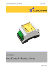
Fig. 1 shows the sketch of the Digital Output DO4 module
with 4 Digital Outputs (DO0 ~ DO3).
All LucidControl modules have two connectors, one USB
connector and an IO- Connector which makes it easy to
setup them.
While the upper USB connector is used for interconnection
with the computer, the lower IO-Connector is used for
inputs and outputs.
DO4 modules are available in different configurations (see
2.1) and because of this the IO Connector may have
different pinouts.
Fig. 1 Digital Output Module
Page 2 of 31
LucidControl DO4, User Manual
2013-02-20
2.1 Configurations
In order to fit most applications three different configurations of the DO4 module are
available which are described in the following.
2.1.1 4 Solid State Relay Outputs (DO4-I)
Fig. 2 shows the DO4-I module which is recommended for
standard applicatons. The versatile module can control lamps
as well as pumps and it can be used to generate general
purpose opto-insulated and potential-free digital outputs.
The emploied solid state relays (SSR) are perfect to generate
pulse-width-modulation (PWM) which allows e.g. controlling
the power of a pump by switching power on and off
periodically.
Despite to mechanical relays SSR are not limited in switching
cycles and are suited for periodical switching as well as for
Fig. 2 DO4 Module with Solid
State Relays
static switching.
A detailed description of solid state relay outputs can be found
in section 2.2.2.1.
2.1.2 4 Transistor Outputs with Open Collector (DO4-O)
While DO4-I modules are preferable for many applications
because of their opto-insulation they are limited in switching
timing.
The DO4-O module shown in Fig. 3 is similar to the DO4-I
module but uses transistors instead of solid state relays which
allow faster switching cycle times.
A detailed description of open-collector outputs can be found
in section 2.2.2.2.
Fig. 3 DO4 Open Collector
Module
Page 3 of 31
LucidControl DO4, User Manual
2013-02-20
2.1.3 4 Mechanical Relay SPDT Outputs (DO4-S)
The DO4-S module uses 4 mechanical “single pole double
throw” (SPDT) relays. This relays have the advantage of behaving
like mechanical switches closing a circuit. This allows not only
switching of electrical power but also switching of measurement
signals e.g. from a temperature sensor which would be distorted
by using solid state relays.
An additional advantage of the DO4-S module is that it can
toggle between two signals.
Fig. 4 DO4 Module with relays
The DO4-S module should not be considered for periodical
switching (e.g. PWM) since the relays are limited in number of
switching cycles. Because of this the DO4-S module does not support the Duty-Cycle
Mode (see 3.1.2).
A detailed description of SPDT outputs can be found in section 2.2.2.3.
2.2 Interface and Interconnection
2.2.1 USB Connection
LucidControl USB modules are connected to the computer by using a standard USB cable
which must not extend a length of 5 m. They are “bus powered” which means that the host
computer supplies the module with power.
Most LucidControl modules are rated with a load current of less than 50 mA. For the DO4S module which drives the mechanical relays a maximum current of 250 mA must be
considered.
Note:
Supplying USB devices with power is not critical using a desktop computer or notebooks
but it must be considered that the total power of one USB port is limited to 500 mA.
Note:
The USB ports of the Raspberry Pi® are limited to 100 mA. This means that maximum two
devices can be connected to a port directly.
Note:
Using an active USB-Hub with its own power supply allows the connection of additional
devices in the case that the host is not able to supply them.
Page 4 of 31
LucidControl DO4, User Manual
2013-02-20
The DO4-S module must not be connected to the Raspberry Pi® directly.
2.2.2 IO Connection
2.2.2.1 DO4-I (SSR)
Fig. 5 shows the connection of the first of the four solid state relay (SSR)
outputs as they are used in the DO4-I module.
When the output is activated the SSR connects terminal 1 with terminal 2,
closing the circuit and switching the lamp in the depicted application on.
For the DO4-I module the polarity of the signal does not play a role. The
positive polarity can be connected to either terminal 1 or terminal 2.
Fig. 5 SSR
Output
One characteristic of the SSR output is the opto-insulation protecting the
electronic behind the SSR (e.g. the host computer). Moreover the outputs are potentialfree i.e. the terminals 1 and 2 are not related to the terminals of any other output.
The outputs connected to the terminals 3/4, 5/6 and 7/8 are identical to 1/2 and each is
able to switch 0,75A / 30V DC.
The outputs are not protected against overcurrent. It must be ensured that the
current does not extend ISSRMax. Otherwise the output may be damaged.
The DO4-I module supports the Reflect Mode, Duty-Cycle Mode and On-Off Mode.
For Duty-Cycle and On-Off Modes the minimum on and off times are limited to TSSRMin.
2.2.2.2 DO4-O (OC)
Fig. 6 shows the connection of the first of the four open collector (OC)
outputs of the DO4-O module.
When the output is activated the transistor connects terminal 1 with
ground and switches the lamp of this application on.
The outputs are not opto-isolated and not potential-free and it is important
Fig. 6 Open
Collector Output
that the positive polarity is connected to the terminals 1, 3, 5 or 7. The
terminals 2, 4, 6 and 8 are internally connected to ground which means that
all Outputs are connected to the same ground namely the ground of the
host computer.
Due to this characteristic it is possible to switch the outputs much faster on and off.
Page 5 of 31
LucidControl DO4, User Manual
2013-02-20
The principal of open collector outputs is shown in Fig.
7. While solid state relays create a connection between
two terminals of the IO-Connector (e.g. 1 and 2) an open
collector output connects one terminal (e.g. 1) to
ground.
Fig. 7 Open Collector Principle
In this application an external power supply VCC and an
external load are connected to terminal 1 and 2 of an
output. The negative Terminal of the power supply VCC must be connected to the terminal
2 (resp. 4, 6 or 8) of the DO4-O module. The load must be connected to terminal 1 (resp. 3,
5 or 7) of the DO4-O module.
If the physical output is set, the transistor is switched on, connecting terminal 1 to ground.
The biggest advantage of Open Collector outputs is the very fast switching time. DO4-O
modules are best suited for applications where fast switching is required e.g. switching or
dimming of lamps especially LEDs with PWM cycles of 100 Hz or faster.
Note:
As Fig. 7 shows the output is not floating, but it is connected to internal ground. In
contrast to solid state relays it must be considered that there is one common ground for
all outputs.
The output is not protected against overcurrent. It must be ensured that the
current does not extend IOCMax. Otherwise the output may be damaged.
The output is not protected against wrong polarization of the input voltages.
Connecting a negative voltage to a positive output pin may damage the output.
The DO4-O module supports Reflect Mode, Duty-Cycle Mode and On-Off Mode.
For Duty Cycle and On-Off Modes the minimum on and off times are limited to TOCMin.
2.2.2.3 DO4-S (SPDT)
Fig. 8 shows the connection of the first of the four single pole rouble throw
(SPDT) relay outputs with its terminals 1, 2 and 3. The DO4-S module has 12
IO terminals instead of 8.
In the example the common contact “C” can be toggled between two
resistors. While the output is deactivated the contact “C” is connected to
Fig. 8 Relay
Output
Page 6 of 31
LucidControl DO4, User Manual
2013-02-20
the contact “NC” (Normally Close). When the output is activated the Contact “C” is
connected to the contact “NO” (Normally Open).
The terminals 1/4/7/10, 2/5/8/11 and 3/6/9/12 are identical.
All outputs of the DO4-S modules are galvanically-insulated and potential-insulated and
therefore can be seen as separate units without interference.
The polarity can be disregarded i.e. it does not play a role which IO is connected to
positive or negative polarity.
If an output is cleared it disconnects the C contact from the NO contact and connects it
with the NC contact. This behavior is called “single pole double throw” (SPDT) and allows
the selection of two different signals (toggling).
Fig. 4 shows that the IO-Connector of the module has not 8 but 12 terminals.
The output is not protected against overcurrent. It must be ensured that the
current does not extend ISPDTMax. Otherwise the output may be damaged.
The DO4-S module supports Reflect Mode and On-Off Mode only. Because of limited
number of switching Duty-Cycle Mode is not supported.
For On-Off Mode the minimum on and off times are limited to TSSRMin.
2.3 Setup of Hard- and Software
Setting up LucidControl hardware is extremely easy:
1 Ensure that no signal is applied to the IO Connector
2 Connect LucidControl via USB with the computer
3 Applies for Microsoft windows only: The system asks for an installation file. This is
not a driver but only an information file (INF). The file can be downloaded from our
website www.lucid-control.com/downloads
4 That’s all. LucidControl switches the green power LED on and the module is ready
for usage.
Page 7 of 31
LucidControl DO4, User Manual
2013-02-20
2.3.1 Microsoft Windows®
As mentioned the installation under Microsoft Windows requires the information file.
After finished installation the Windows Device Manager contains a new serial port (COM).
The module can be accessed using this port.
Note:
Even if more than one module is connected to a computer Windows ensures that the same
serial port number is assigned to the module(s) after restart.
2.3.2 Linux
Despite to Windows installation under Linux the module is usable immediately after
connection without any additional steps. Linux installs /dev/ttyACM devices for any
module connected to the computer.
Note:
By default Linux cannot ensure that the same /dev/ttyACM device is assigned to the same
module on restart. But as long as only one module is connected to the computer it is
ensured that it is accessible via /dev/ttyACM0.
This problem can be solved by the LucidIoCtrl command line tool which can create static
devices always pointing to a specific module. Moreover the device can be given useful
names e.g. dev/digitalIoKitchen.
Please see the section … of the general LucidIo User Manual for more information..
2.3.3 Get command line LucidIoCtrl
LucidIoCtrl command line tool can be downloaded from our website:
www.lucid-control.com/downloads
This page provides the command line tool LucidIoCtrl for different architectures.
After downloading the program can be stored in a folder of choice.
Please see the section … of the general LucidControl User Manual for more information
about this helpful tool..
Page 8 of 31
LucidControl DO4, User Manual
2013-02-20
2.3.4 Ready for Take-Off
After the module was installed successfully (if it was necessary at all) the green Power LED
is switched on signaling that the module is ready for use.
Since the module was preconfigured for standard input mode (see ...) it can be used
without further configuration. The following examples demonstrate the functionality of the
module by using the LucidIoCtrl command line tool.
.
Windows Examples
For all examples it is assumed that the module is connected to COM1.
Setting output channel number 0 to “1”
LucidIoCtrl –dCOM1 –tL –c0 -w1 [ENTER]
Resetting output channel number 0 to “0”
LucidIoCtrl –dCOM1 –tL –c0 –w0 [ENTER]
Reading the outputs of all 4 channels back
->
LucidIoCtrl –dCOM1 –tL –c0,1,2,3 –r [ENTER]
CH0:00 CH1:00 CH2:00 CH3:00
Linux Examples:
For all examples it is assumed that the module is connected to /dev/ttyACM0.
Setting output channel number 0 to “1”
LucidIoCtrl –d/dev/ttyACM0 –tL –c0 –w1 [ENTER]
Resetting output channel number 0 to “0”
LucidIoCtrl –d/dev/ttyACM0 –tL –c0 –w0 [ENTER]
Reading the outputs of all 4 channels back
->
LucidIoCtrl –d/dev/ttyACM0 –tL –c0,1,2,3 –r [ENTER]
CH0:00 CH1:00 CH2:00 CH3:00
Page 9 of 31
LucidControl DO4, User Manual
2013-02-20
3 Module Usage
3.1 Output Modes
This section describes the operation of the different output modes and gives examples
how the outputs can be controlled.
Each of the outputs of the module can work in one of the following modes:
Reflect Mode
Duty-Cycle Mode
On-Off Mode
Physical output value inversion:
Digital outputs distinguish between physical and logical state. The logical state is the
current internal state of the output which can be “0” (cleared) or “1” (set). The logical state
is calculated by the output handling and is normally identical to the physical output state.
Normally, setting the logical output state to “1” sets the physical output state to “1” which
results in an output being enabled.
In the case that the output inversion is activated by setting outDiInverted to “on” the
logical and physical states are inverted which means that the physical output is inverted in
relation to the logical output value. Setting the logical output to “1” clears the physical
output state to “0” which results in an output being disabled.
All output modes support inversion of physical state.
3.1.1 Reflect Mode
Reflect Mode is the simplest output mode and links the value written to an output with the
physical output directly.
Writing “1” to the output causes the output being set immediately.
Writing “0” to the output causes the output being cleared immediately.
By setting and clearing outputs in Reflect Mode any pattern of the output signal can be
generated, but the timing is limited by the communication protocol and the host
computer.
This means e.g. that switching an output on and off every 1ms would need 1000
commands per second. This is not realistic because common operating systems do not
Page 10 of 31
LucidControl DO4, User Manual
2013-02-20
allow such a fast timing. Moreover the communication (e.g. via USB) takes some time.
Altogether this would lead into an inaccurate and non-deterministic timing of the signal.
Duty-Cycle Mode and On-Off Mode prevent this by implementing the critical timing in the
module.
LucidIoCtrl Command Line Tool Example:
Configure output channel 0 for Reflect mode
LucidIoCtrl –dCOM4 –c0 –soutDiMode=reflect [ENTER]
Set output channel 0 to “1”
LucidIoCtrl –dCOM4 –c0 –tL –w1 [ENTER]
… and Set the channel 0 back to “0”
LucidIoCtrl –dCOM4 –c0 –tL –w0 [ENTER]
3.1.2 Duty-Cycle Mode and Generation of PWM
In Duty-Cylce Mode the module switches outputs on and off in a periodical sequence
which is also referred to as PWM (pulse-width-modulation).
By switching an output on and off periodically it is e.g. possible to control the power
consumed by a device and can be used for e.g. controlling the power of a pump or a
heating element. By adding a temperature sensor connected to a LucidControl RI4 module
a temperature control loop can be realized.
Switching a lamp or a LED very fast (TCycle < 10 ms) allows the dimming of them very easily.
Fig. 9 shows the typical periodical signal generated in
Duty-Cycle Mode.
Setting the output value to “1” starts the processing of
output handling until the output value is set to “0”
Fig. 9 Duty-Cycle Mode
which ends the processing after finishing the running
cycle.
The timing of the generated signal is configured by two parameters:
TCycle defines the cycle time (period) of the signal and can be configured by the IO
Configuration Parameter outDiCycleTime.
The IO Configuration Parameter outDiDutyCycle defines the relation of the on-time
TOn and the off-time TOff
o On-time equals to
Page 11 of 31
LucidControl DO4, User Manual
2013-02-20
o Off-time equals to
The resolution of the generated signal is
which means that on-time and off-time have
a resolution of 1 ‰.
Changing the parameters outDiCycleTime or outDiDutyCylce while processing of the DutyCycle outputs is running updates the values immediately.
Physical Output Value Inversion:
Fig. 10 shows the physical output state of the example
above in the case that physical output inversion is
activated by setting the IO Configuration Parameter
outDiInverted to “on”.
Fig. 10 Duty-Cycle Mode Output
Inversion
While the processing of the outputs of both examples is
identical, the figure shows the inverted physical output.
Cancelation of On-Phase:
In the examples above setting the output value to “0”
causes the end of the Duty-Cycle processing.
As long as the logic output is “0” value the running cycle
can be interrupted immediately by setting the logic
Fig. 11 Duty-Cycle Mode Cancel OnPhase
value to “0”. But in the case that the logic output value is
“1” the processing can earliest stop after the on-state
has finished as shown in Fig. 9.
Fig. 11 shows the behavior of the output if the IO Configuration Parameter outDiCanCancel
is set to “on”. This allows stopping the logic on-phase immediately returning to “0” when
the output processing is stopped by setting the output value to “0”.
Updating of Parameters
While output processing is running the IO Configuration Parameters outDiCycleTime and
outDiDutyCycle can be updated at any time. The changed values will be used immediately
i.e. for the running cycle also.
Note:
Mechanical relays have a limited switching capability of approx. 1.000.000 on-off cycles.
Because of this the Duty-Cycle Mode is not available for DO4-S module.
Page 12 of 31
LucidControl DO4, User Manual
2013-02-20
LucidIoCtrl Command Line Tool Example
Configure output channel 0 for Duty-Cycle mode
LucidIoCtrl –dCOM4 –c0 –soutDiMode=dutyCycle [ENTER]
Start processing of PWM signal for output channel 0
LucidIoCtrl –dCOM4 –c0 –tT –w1 [ENTER]
Since the module was preconfigured with TCycle = 1 s and DutyCycle = 50% the output is
switchted 500 ms to “1” and 500 ms to “0”
Changing TCycle to 2 s
LucidIoCtrl –dCOM4 –c0 –soutCycleTime=2000000 [ENTER]
The output is now 1 s switched on and 1 s switched of
Increase DutyCycle = 75%
LucidIoCtrl –dCOM4 –c0 –soutDutyCycle=750 [ENTER]
… and disable processing of output channel 0
LucidIoCtrl –dCOM4 –c0 –tT –w0 [ENTER]
3.1.3 On-Off Mode
In On-Off Mode the output generates a one-time sequence
pattern shown in Fig. 12.
By using On-Off Mode time controlled switching functions (e.g.
Fig. 12 On-Off Mode
used in timing relays) can be realized.
Setting the logic value of the output to “1” starts processing of the
output handling by starting the TOnDelay interval. After TOnDelay has passed the logic output
value changes to “1” and TOnHold interval starts. After TOnHold time has passed the logic value
returns to initial “0” state and the sequence finishes.
In On-Off Mode the following two IO Configuration Parameters are relevant for timing
configuration:
Time TOnDelay is specified by the parameter outDiOnDelay
Time TOnHold is specified by the parameter outDiOnHold
Page 13 of 31
LucidControl DO4, User Manual
2013-02-20
Physical Output Value Inversion:
Fig. 13 shows the inverted physical output value of the example
above in the case that physical output inversion is activated by
setting the IO Configuration Parameter outDiInverted to “on”.
Fig. 13 On-Off Mode
Output Inversion
Cancelation of On-Phase:
Fig. 14 shows the behavior of the output value in the case that IO
Configuration Parameter outDiCanCancel is set to “on” and the
logical output value is set to “0” before TOnHold has passed.
Fig. 14 On-Off Mode
Cancel On Phase
While in the previous Figures the on-phase finishes after TOnHold has
passed outDiCanCancel allows canceling the on-phase immediately
by setting the output value to “0”.
Retrigger of On-Phase:
Fig. 15 shows the output timing sequence with IO Configuration
Parameter outDiCanRetrigger set to “on”.
This setting allows retriggering the on-phase before the logical
output returns to initial “0” value.
Fig. 15 On-Off Mode
Retrigger
Setting the logical output value to “1” before TOnHold has passed
restarts the TOnHold interval again.
Note:
It is save to combine IO Configuration Parameters outDiCanRetrigger=“on” and
outDiCanCancel=”on”. This allows retriggering of on-phase as well as on-phase
cancelation.
LucidIoCtrl Command Line Tool Example
Configure output channel 0 for On-Off mode
LucidIoCtrl –dCOM4 –c0 –soutDiMode=onOff [ENTER]
Since the module was preconfigured with TOnDelay = 1 s and TOnHold = 1 after writing a “1” to
output value of channel 0 will set the output after 1 s for 1 sec returning to “0” finally.
Start processing of output channel 0
LucidIoCtrl –dCOM4 –c0 –tT –w1 [ENTER]
Page 14 of 31
LucidControl DO4, User Manual
2013-02-20
3.2 Timing Limits
Duty-Cycle Mode and On-Off Mode use fast internal timers providing a high resolution
and accuracy.
Module
DO4-I
DO4-O
DO4-S
Timing resolution (tRes)
10 ms
0.5 ms
100 ms
Tab. 1 Timing Resolution
The time tRes given in Tab. 1 defines the minimum timing resolution which is necessary in
order to fulfill the output restrictions of the different output types.
The timing resolution defines the minimum interval for a single on-phase or off-phase of
the output. If a specified or calculated on-time or off-time is lower than tRes the void phase
is skipped.
Example:
The output 0 of DO4-S module is configured for mode Duty-Cycle with TCycle=1 s
(1.000.000 µs) and a DutyCyle of 50‰.
The resulting times are TOn=50 ms and TOff=950 ms. Since TOn violates the tRes constraint
requesting more than 100 ms as minimum interval the on-phase of the output is skipped,
causing the output staying low permanently.
Maximum timing interval
TCycle, TOnDelay and TOnHold have a common maximum limit of 3.600.000 µs (1 hour) for all
modules.
3.3 Commands
After an output was set up correctly and configured it is possible to set the output value or
to read back its state.
Accessing inputs and outputs is a very common task which is mostly identical for all Lucid
Control modules. Please refer to the section 3.2.1.1, 3.2.1.2 and 4.3 of the general
LucidControl manual for comprehensive information covering reading and writing of
inputs and outputs in general.
The following sections describe in detail the commands which are supported by the DO4
module.
Page 15 of 31
LucidControl DO4, User Manual
2013-02-20
3.3.1 SetIo
This command sets one output value.
Mode
Reflect
Value
Value reflects the logic state to the output
Status of the Duty-Cycle Mode processing. “1” refers to enabled
processing, “0” to disabled processing.
Status of the On-Off Mode processing. “1” refers to enabled
processing, “0” to disabled processing.
Duty-Cycle
On-Off
Tab. 2 Output Values
Command
Opcode
SetIo
0x40
Access
Write
LucidIoControl Command Line Tool
Call (-tL)
LucidIoCtrl –d[COMx] –c[Channel] –tL –w[Value]
Note:
When using the LucidIoCtrl command line tool the distinction between the SetIo and
SetIoGroup commands is not necessary since LucidIoCtrl command line tool handles this
automatically.
LucidIoCtrl Command Line Tool Example
Set output channel 0 to “1”:
LucidIoCtrl –dCOM4 –c0 –tL –w1 [ENTER]
Accordingly to Tab. 2 writing of “1” means to set the output in Reflect Mode. In Duty-Cycle
and On-Off Mode writing of “1” means starting of output processing.
Request Frame
OPC
P1
0x40
Channel
P2
Value Type
LEN
Length
Data Field
Value
Page 16 of 31
LucidControl DO4, User Manual
Value
Description
Channel
Number of input or output channel (Range: 0 ~ 3)
Value Type Value Type
Supported Value ypes
Value Type
Value Range
Digital Logic Value
0x00 oder 0x01
(0x00)
Length
Length of the Values in the Data Field
Value
Values accordingly to the Value Type
2013-02-20
Length
1 Byte
Tab. 3 SetIo Request
Response Frame
Status
Length
Status
0
The command does not return any data. In the case of an error the command returns
Execution Status Code documented in section 4.4 of the LucidControl User Manual.
3.3.2 SetIoGroup
This command sets the output values of multiple outputs at once at the same type.
Command
Opcode
SetIoGroup
Access
Write
0x42
LucidIoControl Command Line Tool
Call (-tL)
LucidIoCtrl –d[COMx] –c[Channels] –tL –w[Values]
Channels:
Comma separated list of channels e.g. –c0,1,3
Values:
Comma separated list of values to set e.g. -w1,1,0
LucidIoCtrl Command Line Tool Example
Set output channel 0 to “1”, output channel 2 to “1” and output channel 3 to “0”:
LucidIoCtrl –dCOM4 –c0,2,3 –tL –w1,1,0 [ENTER]
Page 17 of 31
LucidControl DO4, User Manual
Request Frame:
OPC
P1
Channel
0x40
Mask
2013-02-20
P2
LEN
Data Field
Value Type
Length
Values
Value
Channel
Mask
Value
Type
Length
Values
Description
Channel Mask
Specifies the output channels to access
Channel
Bit Position
Value
0
0
0x01
1
1
0x02
2
2
0x04
3
3
0x08
Values are bitwise or combined
Examples:
Accessing channel 0 and 3
Accessing channel 1 and 2
Value Type
Supported Value Types
Value Type
Digital Logic Value
(0x00)
Value = 0x01 OR 0x08 = 0x09
Value = 0x02 OR 0x04 = 0x06
Value Range
Length
0x00 oder 0x01
1 Byte
Length of the Values in the Data Field (One Value for every channel)
Values accordingly to the Value Type
Tab. 4 SetIoGroup Request
Response Frame
Status
Length
Status
0
The command does not return any data. In the case of an error the command returns
Execution Status Code documented in section 4.4 of the LucidControl User Manual.
Example of SetIoGroup
The following request frame sets:
outputs 0 to “1”; output 1 to “1” and output 3 to “0”
Page 18 of 31
LucidControl DO4, User Manual
Request Frame
OPC
0x42
P1
0x0B
2013-02-20
P2
0x00
LEN
Data Field
0x03
Byte
1
0x01
Channel Mask for Param1:
Output Values in Data Field are sorted:
0
0x01
2
0x00
0x01 OR 0x02 OR 0x08 = 0x0B
Channel 0, Channel 1, Channel3
Response Frame:
Status
Length
0x00
0x00
3.3.3 GetIo
Command
Opcode
GetIo
0x46
Access
Read
LucidIoControl Command Line Tool
Call (-tL)
Return
LucidIoCtrl –d[COMx] –c[Channel] –tL –r
CHn:ll
n
ll
Input Channel
Input Digital Value
Note
When using the LucidIoCtrl command line tool the distinction between GetIo and
GetIoGroup commands is not necessary since the program handles this automatically.
LucidIoCtrl Command Line Tool Example
Read output channel 0:
->
LucidIoCtrl –dCOM4 –c0 –tL -r [ENTER]
CH0:01
Request Frame
OPC
P1
0x46
Channel
P2
Value Type
LEN
0
Page 19 of 31
LucidControl DO4, User Manual
2013-02-20
Value
Description
Channel
Number of input or output channel (Range: 0 ~ 3)
Value Type Supported Value Types
Value Type
Value Range
Response Len
Digital Logic Value
0x00 oder 0x01
1 Byte
(0x00)
Tab. 5 GetIo Request
Response Frame:
In case of successful execution the command returns the value of the specified channel
number.
Status
Status
LEN
Length
Data Field
Value(s)
In the case of an error the command returns Execution Status Code documented in section
4.4 of the LucidControl User Manual.
Page 20 of 31
LucidControl DO4, User Manual
2013-02-20
3.3.4 GetIoGroup
This command reads the logic output values of a group of outputs of the same Value Type.
See also section 3.3.3.
Command
Opcode
GetIoGroup
Access
Read
0x48
LucidIoControl Command Line Tool
Call (-tL)
LucidIoCtrl –d[COMx] –c[Channels] –tL –r
Return
Channels:
Comma separated list of channels e.g. –c0,1,3
List of values sorted from lower to higher channels
CHn:xx
n
Input Channel
ll
Input Digital Value
LucidIoCtrl Command Line Tool Example
Read output values of channel 0, 1 and 3:
LucidIoCtrl –dCOM4 –c0,1,3 –tL –r [ENTER]
CH0:00 CH1:01 CH3:01
Request Frame
OPC
0x48
P1
Channel
Mask
P2
LEN
Value Type
0
Page 21 of 31
LucidControl DO4, User Manual
2013-02-20
Value
Channel
Mask
Value
Type
Description
Channel Mask
Specifies the output channels to access
Channel
Bit Position
Value
0
0
0x01
1
1
0x02
2
2
0x04
3
3
0x08
Values are bitwise or combined
Examples:
Accessing channel 0 and 3
Accessing channel 1 and 2
Supported Value Types
Value Type
Digital Logic Value
(0x00)
Value = 0x01 OR 0x08 = 0x09
Value = 0x02 OR 0x04 = 0x06
Value Range
Response Len
0x00 oder 0x01
1 Byte
Tab. 6 GetIoGroup Request
Response Frame:
In case of successful execution the command returns the read values of the channels
specified in the Channel Mask.
Status
Status
LEN
Length
Data Field
Value
In the case of an error the command returns Execution Status Code documented in section
4.4 of the LucidControl User Manual.
Example of GetIoGroup Request:
The following request frame reads outputs 0, 1 and 3
Opcode
P1
P2
Length
0x48
0x0B
0x00
0x00
Channel Mask (P1):
0x01 OR 0x02 OR 0x08 = 0x0B
Response Frame:
For input 0 = “0”, input 2 = “1” and input 3 = “1”
Values in Data Field are in ascending order Channel 0, Channel 1, Channel3.
Page 22 of 31
LucidControl DO4, User Manual
2013-02-20
Header Field
Status
LEN
0x00
0x03
Value
Channel 0
0x00
Data Field
Value
Channel 1
0x01
Value
Channel 3
0x01
3.4 Parameters
LucidControl modules allow configuration by a set of System Configuration Parameters
and IO Configuration Parameters.
The Parameters are accessible via the SetParam and GetParam command which are
described in sections 4.3.5 and 4.3.6 of the LucidControl User Manual.
The relevance of some parameter may depend on the operation mode described in section
3.1.
3.4.1 outDiValue
This IO Configuration Parameter reflects the value or the state of the output (see Tab. 2).
In the case the output is in Reflect mode the outDiValue contains the logic value of the
output.
In the case that the output is in Duty-Cycle or On-Off mode outDiValue contains “1” in the
case that the output processing is running and “0” in the case that the output processing is
stopped.
Parameter
Address
Values
Default Value
Parameter Name
Call (Set)
Call (Set
outDiValue
Access
0x1000
Output Value
0x00
Parameter Type
LucidIoControl Command Line Tool
outDiValue
Parameter Values
Read / Write
1 Byte unsigned
0x00 or 0x01
LucidIoCtrl –d[COMx] –c[Channel] –soutDiValue=[Value]
{-p} {--default}
LucidIoCtrl –d[COMx] –c[Channel] –goutDiValue
LucidIoCtrl Command Line Tool Example
Set value of output channel 0 to “1” and make the setting persistent:
LucidIoCtrl –dCOM4 –c0 –soutDiValue=1 –p [ENTER]
Read value or state of output channel 0:
->
LucidIoCtrl –dCOM4 –c0 –goutDiValue [ENTER]
outDiValue=0
Page 23 of 31
LucidControl DO4, User Manual
2013-02-20
Note:
For normal operation it is recommended to use the functions SetIo (3.3.1) and GetIo (3.3.3)
in order to write or read to an output.
Setting outDiValue allows making a value persistent by means that the output value is
restored after the module is restarted.
3.4.2 outDiMode
This IO Configuration parameter configures the operation mode of the output.
Parameter
Address
Values
Default Value
Parameter Name
Call (Set)
Call (Get)
outDiMode
0x1100
Output Mode
Byte
0x00
0x01
0x08
0x0A
Access
Read / Write
Mode
Inactive
Reflect
On-Off
Duty-Cycle
0x00
Parameter Type
LucidIoControl Command Line Tool
outDiMode
Parameter Values
1 Byte unsigned
incactive / reflect /
onOff / dutyCycle
LucidIoCtrl –d[COMx] –c[Channel] –soutDiMode=[Value] {-p}
{--default}
LucidIoCtrl –d[COMx] –c[Channel] –goutDiMode
LucidIoCtrl Command Line Tool Example
Set operation mode of channel 0 to Duty-Cycle Mode and make the setting persistent.
LucidIoCtrl –dCOM4 –c0 –soutDiMode=dutyCycle –p [ENTER]
Read the operation mode of channel 0
LucidIoCtrl –dCOM4 –c0 –goutDiMode [ENTER]
outDiMode=dutyCycle
3.4.3 Bit Parameter outDiFlags
This IO Configuration Parameter groups parameters which are represented by one bit e.g.
having an “on” or “off” state only).
Page 24 of 31
LucidControl DO4, User Manual
Parameter
Address
Values
Default Value
2013-02-20
outDiFlags
Access
Read / Write
0x1101
The “bit container” consists of the following parameters.
Bit Parameter
Bit Postion
outDiCanRetrigger
Bit 0
outDiCanCancel
Bit 1
outDiInverted
Bit 2
0x00
Parameter Type
1 Byte unsigned
Note:
The parameter outDiFlags cannot be accessed by the Command Line Tool. The Bit
Parameters should be used instead.
Note:
When outDiFlags is changed by the SetParam command which is described in section 4.3.5
of the LucidControl User Manual the current setting of outDiFlags must be read before
updating it in order to prevent overwriting other Bit Parameters.
3.4.3.1 outDiInverted
This Bit Parameter configures the inversion of the physical output value.
See output modes descriptions in section 3.1 for more information.
Parameter
Address
Values
Default Value
Parameter Name
Call (Set)
Call (Get)
outDiFlags
0x1101
Bit Parameter
outDiInverted
Access
Read / Write
Bit Parameter outDiFlags
Bit Postion
Bit 2
Off
Parameter Type
LucidIoControl Command Line Tool
outDiInverted
Parameter Values
1 Bit
on / off
LucidIoCtrl –d[COMx] –c[Channel] –soutDiInverted=[Value]
{-p} {--default}
LucidIoCtrl –d[COMx] –c[Channel] –goutDiInverted
LucidIoCtrl Command Line Tool Example
Enable inversion of physical output channel 0 and make the setting persistent.
LucidIoCtrl –dCOM4 –c0 –soutDiInverted=on –p [ENTER]
Read inversion configuration of physical output channel 0
->
LucidIoCtrl –dCOM4 –c0 –goutDiInverted [ENTER]
outDiInverted=on
3.4.3.2 outDiCanCancel
Page 25 of 31
LucidControl DO4, User Manual
2013-02-20
This Bit Parameter configures the output on-phase cancelation.
See the output modes descriptions in section 3.1 for more information.
Parameter
Address
Values
Default Value
Parameter Name
Call (Set)
Call (Get)
outDiFlags
0x1101
Bit Parameter
outDiCanCancel
Access
Read / Write
Bit Parameter outDiFlags
Bit Postion
Bit 1
Off
Parameter Type
LucidIoControl Command Line Tool
outDiCanCancel
Parameter Values
1 Bit
on / off
LucidIoCtrl –d[COMx] –c[Channel] –soutDiCanCancel=[Value]
{-p} {--default}
LucidIoCtrl –d[COMx] –c[Channel] –goutDiCanCancel
LucidIoCtrl Command Line Tool Example
Enable output cancelation output channel 0 and make the setting persistent.
LucidIoCtrl –dCOM4 –c0 –soutDiCanCancel=on –p [ENTER]
Read configuration of output cancelation of output channel 0
->
LucidIoCtrl –dCOM4 –c0 –goutDiCanCancel [ENTER]
outDiCanCancel=on
3.4.3.3 outDiCanRetrigger
This Bit Parameter configures the on-phase retrigger function of the output.
See the output modes descriptions in section 3.1 for more information.
Parameter
Address
Values
Default Value
Parameter Name
Call (Set)
Call (Get)
outDiFlags
0x1101
Bit Parameter
outDiCanRetrigger
Access
Read / Write
Bit Parameter outDiFlags
Bit Postion
Bit 0
Off
Parameter Type
LucidIoControl Command Line Tool
outDiCanRetrigger Parameter Values
1 Bit
on / off
LucidIoCtrl –d[COMx] –c[Channel]
–soutDiCanRetrigger=[Value] {-p} {--default}
LucidIoCtrl –d[COMx] –c[Channel] –goutDiCanRetrigger
LucidIoCtrl Command Line Tool Example
Enable output retrigger of channel 0 and make the setting persistent.
LucidIoCtrl –dCOM4 –c0 –soutDiCanRetrigger=on –p [ENTER]
Page 26 of 31
LucidControl DO4, User Manual
2013-02-20
Read output retrigger configuration of output channel 0
->
LucidIoCtrl –dCOM4 –c0 –goutDiCanRetrigger [ENTER]
outDiCanRetrigger=on
3.4.4 outDiCycleTime
This IO Configuration Parameter specifies the cycle time TCycle of an output in Duty-Cycle
Mode.
Parameter
Address
Values
Default Value
Parameter Name
Call (Set)
Call (Get)
outDiCycleTime
Access
0x1110
TCycle in µs (micro seconds)
TRes ≤ TCycle ≤ 1 h
1,000,000 (1 s)
Parameter Type
LucidIoControl Command Line Tool
outDiCycleTime
Parameter Values
Read / Write
4 Bytes unsigned
Time [µs]
LucidIoCtrl –d[COMx] –c[Channel] –sinDiCycleTime=[Time]
{-p} {--default}
LucidIoCtrl –d[COMx] –c[Channel] –ginDiCycleTime
LucidIoCtrl Command Line Tool Example
Set TCycle of input channel 0 to 1.5 s and make the setting persistent.
LucidIoCtrl –dCOM4 –c0 –sinDiCycleTime=1500000 –p [ENTER]
Read TCycle parameter of input channel 0
->
LucidIoCtrl –dCOM4 –c0 –ginDiCycleTime [ENTER]
inDiCycleTime=1500000
Note:
Timing limits for TRes (see 3.2) have to be considered.
3.4.5 outDiDutyCycle
This IO Configuration Parameter specifies the Duty-Cycle of an output in Duty-Cycle mode.
Page 27 of 31
LucidControl DO4, User Manual
Parameter
Address
Values
Default Value
Parameter Name
Call (Set)
Call (Get)
outDiDutyCycle
Access
0x1111
Duty Cycle in ‰ (1 / 1000)
500 (50%)
Parameter Type
LucidIoControl Command Line Tool
outDiDutyCycle
Parameter Values
2013-02-20
Read / Write
2 Bytes unsigned
Duty Cycle [‰]
LucidIoCtrl –d[COMx] –c[Channel] –soutDiDutyCycle=[Time]
{-p} {--default}
LucidIoCtrl –d[COMx] –c[Channel] –goutDiDutyCylce
LucidIoCtrl Command Line Tool Example
Set Duty Cycle ot output channel 0 to 20% and make the setting persistent.
LucidIoCtrl –dCOM4 –c0 –soutDiDutyCycle=200 –p [ENTER]
Read Duty Cycle setting for output channel 0
LucidIoCtrl –dCOM4 –c0 –goutDiDutyCycle [ENTER]
outDiDutyCycle=200
Note:
Timing limits (see 3.2) have to be considered.
3.4.6 outDiOnDelay
This IO Configuration Parameter specifies the on-delay time TOnDelaye of an output in OnOff Mode.
Parameter
Address
Values
Default Value
Parameter Name
Call (Set)
Call (Get)
outDiOnDelay
Access
0x1112
TOnDelay in µs (micro seconds)
TRes ≤ TOnDelay ≤ 1 h
1,000,000 (1 s)
Parameter Type
LucidIoControl Command Line Tool
outDiOnDelay
Parameter Values
Read / Write
4 Bytes unsigned
Time [µs]
LucidIoCtrl –d[COMx] –c[Channel] –soutDiOnDelay=[Time]
{-p} {--default}
LucidIoCtrl –d[COMx] –c[Channel] –goutDiOnDelay
LucidIoCtrl Command Line Tool Example
Set TOnDelay for output channel 0 to 520 ms and make the setting persistent.
LucidIoCtrl –dCOM4 –c0 –soutDiOnDelay=520000 –p [ENTER]
Read TOnDelay setting for output channel 0
->
LucidIoCtrl –dCOM4 –c0 –goutDiOnDelay [ENTER]
outDiOnDelay=520000
Note:
Timing limits (see 3.2) have to be considered.
Page 28 of 31
LucidControl DO4, User Manual
2013-02-20
3.4.7 outDiOnHold
This IO Configuration Parameter specifies the on-hold time TOnHold of an output in On-Off
Mode.
Parameter
Address
Values
Default Value
Parameter Name
Call (Set)
Call (Get)
outDiOnHold
Access
0x1113
TOnHold in µs (micro seconds)
TRes ≤ TOnHold ≤ 1 h
1,000,000 (1 s)
Parameter Type
LucidIoControl Command Line Tool
outDiOnHold
Parameter Values
Read / Write
4 Bytes unsigned
Time [µs]
LucidIoCtrl –d[COMx] –c[Channel] –soutDiOnHold=[Time]
{-p} {--default}
LucidIoCtrl –d[COMx] –c[Channel] –goutDiOnHold
LucidIoCtrl Command Line Tool Example
Set TOnHold for output channel 0 to 1200 ms and make the setting persistent.
LucidIoCtrl –dCOM4 –c0 –soutDiOnHold=1200000 –p [ENTER]
Read TOnHold setting for output channel 0
->
LucidIoCtrl –dCOM4 –c0 –goutDiOnHold [ENTER]
outDiOnHold=1200000
Note:
Timing limits (see 3.2) have to be considered.
Page 29 of 31
LucidControl DO4, User Manual
2013-02-20
4 Specification
Parameter
Condition
Outputs
No of Output Channels
Outputs - Electrical Characteristics
DO4-I
Maximum Rated Load
DO4-O
Current
DO4-S
DO4-I
Maximum Rated Load
DO4-O
Voltage
DO4-S
Maximum On Resistance
DO4-I
DO4-O
DO4-S
Insulation Resistance
DO4-S
Insulation Voltage
DO4-I
DO4-S
Outputs – Timing Characteristic
DO4-I
Minimum Resolution
DO4-O
tRes
DO4-S
TCycle, TOnDelay, TOnHold
Module – Communication
USB
Module – Electrical Characteristics
Power Supply
Maximum Rated Supply
Current
Module – Environment
Temperature
Humidity
Module – Housing
Dimensions L x W x H
Weight (in total)
Assembly
Protection Class (DIN 40050)
DO4-I
DO4-O
DO4-S
Storage
Operation
Value
4
ISSRMax
IOCMax
ISPDTMax
USSRMax
UOCMax
USPDTMax
RSSR
ROC
RSPDT
750 mA
750 mA
750 mA
30 V
30 V
30 V
0.25 Ω
tbd
0.1 Ω
1 GΩ
1,000 V
400 V AC for 1 minute
10 ms
0.5 ms
100 ms
tRes < T < 3600 s
2.0 Full Speed CDC Profil
Supplied with +5V by USB
No additional Power Supply
needed.
40 mA
40 mA
250 mA
-20 °C … +70 °C
0 °C … +55 °C
< 85 % RH, non-condensing
90 x 54 x 62 mm
120 g
Rail-Mount (EN 50022, TS35)
IP20
Page 30 of 31
LucidControl DO4, User Manual
2013-02-20
Module - Interconnection
Plug-In Terminal 8-way
1,5 mm² wire
Plug-In Terminal 8-way
1,5 mm² wire
Plug-In Terminal 12-way
1,5 mm² wire
DO4-I
Terminal Clamp
DO4-O
DO4-S
Module - Indicators
Operation and Error Indicator
Communication Indicator
Indicator for Output State (Enabled / Disabled)
Software
Supported Systems
Windows® XP, Windows® Vista,
Windows® 7
Ubuntu, Raspbian, Debian
5 Order Information and Accessories
Digital Output Product Family
Order Code
Product
LucidControl Digital Output USB Module 4LCTR-DO4-I
Channels with Solid State Relays (SSR)
LucidControl Digital Output USB Module 4LCTR-DO4-O
Channels with Open Collectors (OC)
LucidControl Digital Output USB Module 4LCTR-DO4-S
Channels with Relays (SPDT)
The following accessories are available:
Order Code
LCTR-AK1710-8
LCTR-AK1710-12
Product
Plug-In Terminal 8-way 1,5 mm² wire
Plug-In Terminal 12-way 1,5 mm² wire
deciphe it GmbH
Schäferstr. 5
87600 Kaufbeuren / Germany
www.lucid-control.com
Page 31 of 31