1
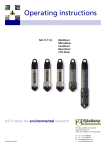
Operating Instructions Diver-Suite® - Water Level Loggers Mini - Diver Micro- Diver Cera- Diver Baro- Diver CTD- Diver The manual should be read before the Diver is installed or operated. Always use the standard packaging material when transporting the Diver. To ensure proper functioning, please avoid the following: • • • • Operation outside of specified pressure range. Shock - Hitting or falling onto hard surface or falling into groundwater. Operation outside of specified temperature range. Extreme magnetic or electrical fields. Note: Use only the CeraDiver or CTD-Diver in seawater. Van Walt Ltd | Prestwick Lane | Grayswood | Haslemere | Surrey | GU27 2DU | Tel. 01428 661 660 | Fax. 01428 656 808 | www.vanwalt.com MA169V1_25/10/2012_TD Operating Instructions Diver-Suite® - Water Level Loggers Product Manual Schlumberger Water Services Delftechpark 20 PO Box 553 2600 AN Delft The Netherlands Tel: +31 (0)15 – 275 5000 www.swstechnology.com Version January 2010 All rights reserved. Nothing in this publication may be duplicated, stored in a computerised data file or made public in any form or manner whatsoever, be it electronic, mechanical, in photocopies, recordings or in any other way without prior written permission from Schlumberger Water Services Netherlands B.V. Van Walt Ltd | Prestwick Lane | Grayswood | Haslemere | Surrey | GU27 2DU | Tel. 01428 661 660 | Fax. 01428 656 808 | www.vanwalt.com Operating Instructions Diver-Suite® - Water Level Loggers Table of Contents Introduction About this manual Operating principle Measuring water levels Measuring temperature Diver types Software Diver-Office Diver-Pocket 1 1 2 5 6 7 7 7 8 Technical Information General Calibration Procedure Manufacturer’s Certificate Specifications Baro-Diver, Mini-Diver, Micro-Diver and Cera-Diver General Pressure Accuracy of pressure measurements Maximum pressure variations Nominal pressure variations 9 9 9 10 10 10 13 13 15 15 15 Diver Installation and Maintenance Introduction Installation in a monitoring well Installation in Surface Waters The use of Divers at elevations Baro-Diver Use in seawater Diver maintenance 16 16 16 18 19 19 19 19 CTD-Diver Measuring conductivity Example Calibration of the CTD-Diver Field calibration Important: 20 20 20 20 21 21 FAQ Appendix I – Use of Divers at elevations Index 23 26 27 Van Walt Ltd | Prestwick Lane | Grayswood | Haslemere | Surrey | GU27 2DU | Tel. 01428 661 660 | Fax. 01428 656 808 | www.vanwalt.com Operating Instructions Diver-Suite® - Water Level Loggers About this manual This manual contains information about Schlumberger Water Services (SWS)’s Divers®. It contains a description of the Mini- Diver (11.11.01.xx), Micro-Diver (11.11.02xx), Cera-Diver (11.11.03.xx), Baro-Diver (11.11.55.01) and the CTD-Diver (11.11.59.xx). The number in brackets designates the Diver model. This section contains a brief introduction to the Diver’s measurement principles, an instrument designed to measure groundwater levels and temperatures. Furthermore, a brief description of the software that can be used in conjunction with the Divers is provided. The next section contains the technical specifications for each type of Diver. Section 3 covers the installation of Divers in monitoring wells and in surface waters. This is followed by a description of how to maintain a Diver. Section 4 discusses conductivity measurements using the CTD-Diver and conductivity calibration. The last section includes the answers to frequently asked questions. Operating principle The Diver is a datalogger designed to measure water levels. Measurements are subsequently stored in the Diver's internal memory. The Diver consists of a pressure sensor designed to measure water pressure, a temperature sensor, memory for storing measurements and a battery. The Diver is an autonomous datalogger that can be programmed by the user. Figure 1 Van Walt Ltd | Prestwick Lane | Grayswood | Haslemere | Surrey | GU27 2DU | Tel. 01428 661 660 | Fax. 01428 656 808 | www.vanwalt.com 1 Operating Instructions Diver-Suite® - Water Level Loggers Measuring water levels All Divers establish the height of a water column by measuring the water pressure using the built-in pressure sensor. As long as the Diver is not submerged in water it measures atmospheric pressure, just like a barometer. Once the Diver is submerged this is supplemented by the water’s pressure: the higher the water column the higher the measured pressure. The height of the water column above the Diver's pressure sensor is determined on the basis of the measured pressure. To measure these variations in atmospheric pressure a Baro-Diver is installed for each site being measured. The barometric compensation for these variations in atmospheric pressure is subsequently effected using SWS’ Diver-Office software package. The compensated values can be related to a reference point such as the top of the monitoring well or a vertical reference datum, for example the Amsterdam Ordnance Datum (Normaal Amsterdams Peil (NAP)). Theory This section explains how to calculate the water level in relation to a vertical reference datum using the Diver and Baro-Diver’s measurements. The figure below represents a typical example of a monitoring well in which a Diver has been installed. In this case we are therefore interested in the height of the water level (WL) in relation to the vertical reference datum. If the water level is situated above the reference datum it has a positive value and a negative value if it is situated below the reference datum. The top of casing (ToC) is measured in relation to the vertical reference datum and is denoted in the diagram below as ToC cm. The Diver is suspended with a cable with a length equal to CL cm. The Baro-Diver measures the atmospheric pressure (pbaro) and the Diver measures the pressure exerted by the water column (WC) and the atmospheric pressure (pDiver). Van Walt Ltd | Prestwick Lane | Grayswood | Haslemere | Surrey | GU27 2DU | Tel. 01428 661 660 | Fax. 01428 656 808 | www.vanwalt.com 2 Operating Instructions Diver-Suite® - Water Level Loggers Figure 2 <<<< Translation of Diagram >>> KL = CL (cable length) WK = WC (water column) WN = WL (water level) BKPB = ToC (Top of Casing) Verticaal referentievlak = Vertical Reference Datum (VRD) The water column (WC) above the Diver can be expressed as: 1. 2. WC = 9806.65…… where p is the pressure in cmH2O, g is the acceleration due to gravity (9.81 m/s2) and ñ is the density of the water (1,000 kg/m3). The water level (WL) in relation to the vertical reference datum can be calculated as follows: WL = ToC – CL + WC 3. Van Walt Ltd | Prestwick Lane | Grayswood | Haslemere | Surrey | GU27 2DU | Tel. 01428 661 660 | Fax. 01428 656 808 | www.vanwalt.com 3 Operating Instructions Diver-Suite® - Water Level Loggers WL = ToC – CL + 9806.65……… If the cable length is not exactly known, it can be determined using a manual measurement. From the figure below it is clear that the manual measurement (MM) is taken from the top of casing to the water level. The value of the water level is positive unless, in exceptional circumstances, the water level is situated above the top of casing. 4. The cable length can now be calculated as follows: CL = MM + WC where the water column (WC) is calculated on the basis of the measurements taken by the Diver and the BaroDiver. Figure 3 Comments: - If the pressure measured by the Diver and the Baro-Diver is measured at different points in time, it is necessary to interpolate. The software automatically performs this interpolation. - It is possible to enter manual measurements into the software. The software subsequently automatically calculates the cable length. Example The top of casing is measured to be 150 cm above the Amsterdam Ordnance Datum (Normaal Amsterdams Peil (NAP)). ToC = 150 cm. The cable length is not exactly known and is therefore measured manually. It turns out to be 120 cm: MM = 120 cm. The Diver measures a pressure of 1,170 cmH2O and the Baro-Diver measures a pressure of 1,030 cmH2O. Substituting these values into equation (1), results in a water column of 140 cm above the Diver: WC = 140 cm. Substituting the values of the manual measurement and the water column in equation (4) results in the following cable length: CL = 120 +140 = 260 cm. The water level in relation to the NAP can now be easily calculated using equation (2): WL = 150 – 260 + 140 = 30 cm above NAP. Van Walt Ltd | Prestwick Lane | Grayswood | Haslemere | Surrey | GU27 2DU | Tel. 01428 661 660 | Fax. 01428 656 808 | www.vanwalt.com 4 Operating Instructions Diver-Suite® - Water Level Loggers Measuring temperature All Divers measure the groundwater temperature. This can, for example, provide information about groundwater flows. This also makes it possible to determine the diffusion of (polluted) water. The temperature is measured using a semiconductor sensor. This sensor not only measures the temperature, but at the same time also uses the value of the temperature to compensate the pressure sensor and electronics (incl. the crystal clock) for the effects of temperature. Van Walt Ltd | Prestwick Lane | Grayswood | Haslemere | Surrey | GU27 2DU | Tel. 01428 661 660 | Fax. 01428 656 808 | www.vanwalt.com 5 Operating Instructions Diver-Suite® - Water Level Loggers Diver types Various types of Divers are available. All Divers measure the absolute pressure and temperature. Absolute pressure is defined as the pressure of the water column above the Diver plus the atmospheric pressure. Consequently, an atmospheric pressure measurement is required to determine the water level. The summary below explains the differences between the various Diver types. Mini-Diver. This is the basic Diver, manufactured using a stainless steel (316 L) casing with a 22 mm diameter. The Mini-Diver is capable of storing a maximum of 24,000 measurements (pressure and temperature). Micro-Diver. This is the smallest Diver with a diameter of 18 mm and a stainless steel (316 L) casing. The Micro-Diver is capable of storing a maximum of 48,000 measurements. This Diver is suitable for pipes with a diameter of at least 20 mm. Cera-Diver. This Diver comes with a 22 mm diameter ceramic casing and is suitable for use in semisaline water and seawater or in other aggressive environments. The Cera-Diver is capable of storing a maximum of 48,000 measurements. CTD-Diver. In addition to taking pressure and temperature measurements, this Diver also measures the water’s conductivity. The 22 mm diameter ceramic casing is suitable for salt water applications. The CTD-Diver is capable of storing a maximum of 48,000 measurements. Baro-Diver. This Diver measures atmospheric pressure and is used to compensate for the variations in atmospheric pressure measured by the other Divers. The stainless steel (316 L) casing has a diameter of 22 mm. The Micro-Diver, Cera-Diver and CTD-Diver incorporate a greater range of functionality than the Mini-Diver and Baro-Diver. These last two Divers only offer a fixed measurement option. This means that the Diver takes measurements on the basis of user-defined intervals. The other Divers offer the following measurement options: - Pre-programmed pump tests or user-defined pump tests. - Average values over a specified time period. - An event-based option. In this case the Diver only stores measurements once the percentage variation limit set for the pressure or conductivity (CTD-Diver) measurement is exceeded. This percentage variation can be specified by the user. For applications in surface waters it is possible to average the values over a specified period. The average values are then stored. The effects of waves are ‘averaged out’ this way. Van Walt Ltd | Prestwick Lane | Grayswood | Haslemere | Surrey | GU27 2DU | Tel. 01428 661 660 | Fax. 01428 656 808 | www.vanwalt.com 6 Operating Instructions Diver-Suite® - Water Level Loggers Software Diver-Office Diver-Office is a software package used in conjunction with every type of Diver described in this manual. The latest version of Diver-Office can be downloaded at any time from the website www.swstechnology.com. Diver-Office operates under all current versions of Microsoft Windows and is easy to install on a laptop or PC. When new versions of Microsoft Windows are released, the website www.swstechnology.com contains further information concerning the supported Windows versions, etc. The site will always provide the latest Diver-Office version as a free download/upgrade. Diver-Office software makes it possible to communicate with Divers and/or to start/stop them. The measurement data recorded by the Divers can be read out at any time. You have the option of reviewing, compensating for variations in atmospheric pressures, printing or exporting the measurement data to various file formats for processing by other software. All values and settings are stored in a database. Furthermore, the raw Diver data is also stored as a file. The software program’s manual contains additional information about the operation of Diver-Office. Figure 5 Van Walt Ltd | Prestwick Lane | Grayswood | Haslemere | Surrey | GU27 2DU | Tel. 01428 661 660 | Fax. 01428 656 808 | www.vanwalt.com 7 Operating Instructions Diver-Suite® - Water Level Loggers Diver-Pocket Diver-Pocket was specifically designed for field use. Diver-Pocket is a software application that runs on a Pocket PC. The Diver-Pocket is available in two versions: Diver-Pocket Reader is a version designed exclusively for reading out Divers. With this version it is not possible to change settings, inadvertently or otherwise. Stopping/starting a Diver also is not possible with this version. The only thing that the Reader is capable of is reading out the Diver’s data. Diver-Pocket Manager is a version that, in addition to reading out the Diver’s data, can also be used to start/stop and program the Diver. The files collected with Diver-Pocket can subsequently be downloaded to a computer. This is however not necessary for importing the Diver-Pocket data into Diver-Office. Diver-Office comes equipped with an import function that is capable of flawlessly locating these files on an interconnected Pocket PC. The import is fast and flawless. The software program’s manual contains additional information about how to work with a Diver-Pocket. Figure 6 Technical Information Van Walt Ltd | Prestwick Lane | Grayswood | Haslemere | Surrey | GU27 2DU | Tel. 01428 661 660 | Fax. 01428 656 808 | www.vanwalt.com 8 Operating Instructions Diver-Suite® - Water Level Loggers Technical Information General The Diver is a datalogger housed in a cylindrical casing with a suspension eye at the top. The suspension eye can be unscrewed and is designed to install the Diver into the monitoring well and protects the optical connector. The electronics, sensors and battery are installed maintenance-free into the casing. The Diver may not be opened. In case of any complaints, please contact your supplier. The name of the datalogger, the model number, the measurement range and the serial number (SN) are clearly identified on the side of the Diver. This information is burnt-in using a laser and is consequently chemically neutral and inerasable. Examples Calibration Procedure The Diver is fine-tuned and tested in accordance with a predefined procedure prior to delivery. The most important test is the calibration (verification of the measurements against a higher standard). The Diver measures pressure and is conventionally calibrated in centimetres of water column (cmH2O). The relationship of the pressure in cmH2O to the pressure in millibars is defined as follows: 1 mbar = 1.01972 cmH2O or 1 cmH2O = 0.980665 mbar The Diver is completely submerged in a water bath during the calibration. The temperature of the water bath is stabilised at 15C and 35C. The Diver is calibrated at 15C as well as 35C. Variations in pressure are created at these two calibration temperatures. The variations in pressure consist of a series of increasing and decreasing pressure readings at 10%, 30%, 50%, 70% and 90% of the total range. Manufacturer’s Certificate The Diver passes inspection if it meets all specifications. A manufacturer’s certificate is available upon request when the Diver is supplied. Van Walt Ltd | Prestwick Lane | Grayswood | Haslemere | Surrey | GU27 2DU | Tel. 01428 661 660 | Fax. 01428 656 808 | www.vanwalt.com 9 Operating Instructions Diver-Suite® - Water Level Loggers Specifications Aside from the Baro-Diver (art.no. 11.11.55.01) for atmospheric pressure and temperature measurements, there are 12 Diver versions for pressure and temperature measurements and 3 CTD-Diver versions for pressure, temperature and conductivity measurements. The summary below summarises the measurement ranges of the water columns that the Divers are capable of measuring: Mini-Diver: - Up to 10 metres (11.11.01.02) - Up to 20 metres (11.11.01.04) - Up to 50 metres (11.11.01.06) - Up to 100 metres (11.11.01.08) Micro-Diver: - Up to 10 metres (11.11.02.02) - Up to 20 metres (11.11.02.04) - Up to 50 metres (11.11.02.06) - Up to 100 metres (11.11.02.08) Cera-Diver: - Up to 10 metres (11.11.03.02) - Up to 20 metres (11.11.03.04) - Up to 50 metres (11.11.03.06) - Up to 100 metres (11.11.03.08) CTD-Diver: - Up to 10 metres (11.11.59.01) - Up to 50 metres (11.11.59.02) - Up to 100 metres (11.11.59.03) Baro-Diver: - Barometric variations (11.11.55.01) Baro-Diver, Mini-Diver, Micro-Diver and Cera-Diver These Diver types meet the following general specifications: Diameter: Ø22 mm Length: Weight: 90 mm incl. suspension eye approx 70 grams Protection class: Ø18 mm Ø22 mm approx 50 grams approx 55 grams IP68, 10 years continuously submerged in water at 100 m Van Walt Ltd | Prestwick Lane | Grayswood | Haslemere | Surrey | GU27 2DU | Tel. 01428 661 660 | Fax. 01428 656 808 | www.vanwalt.com 10 Operating Instructions Diver-Suite® - Water Level Loggers Storage/ Transport temp: Operating temp: -20°C to 80°C (affects battery life) 0°C to 50°C Material Casing: 316L stainless steel 316L stainless steel (active substance (active substance no. .4404) no. 1.4404) Pressure sensor: Alumina (Al2O3) Zirconia (ZrO2) Suspension eye/ nose cone: Akulon (reinforced with fibreglass) Communication: Memory capacity: 24,000 measurements Memory: Optically separated 48,000 48,000 measurements measurements Non-volatile memory. A measurement consists of date/time/level/temperature Sampling rate: 0.5 sec to 99 hours Sampling options: − Fixed interval − Event-based − Pump test Yes Yes Yes Yes Yes Yes Yes Yes Yes No (to be configured by user) No No Battery life*: 10 years, depending on use − Resources Theoretical capacity: 5 million measurements 2000× memory readouts 2000× programming Clock accuracy: Better than ± 1 minute per year at 250C Better than ± 5 minutes per year within the calibrated temperature range CE marking: Emissions: EMC in accordance with the 89/336/EEC directive Basic EN 61000-4-2 standard EN 55022 (1998) + A1 (2000) + A2 (2003), Class B Immunity: EN 55024 (1998) + A1 (2000) + A2 (2003) Certificate number: 06C00301CRT01 06C00300CRT01 06C00299CRT01 Van Walt Ltd | Prestwick Lane | Grayswood | Haslemere | Surrey | GU27 2DU | Tel. 01428 661 660 | Fax. 01428 656 808 | www.vanwalt.com 11 Operating Instructions Diver-Suite® - Water Level Loggers CTD-Diver Diameter:Ø22 mm Length: 135 mm incl. suspension eye Weight: Approx 100 grams Material casing: Zirconia (ZrO2) Protection class: Memory capacity: IP68, 10 years continuously submerged in water @ 100 m 48,000 measurements Sampling rate: - Fixed interval 1 sec to 99 hours Sampling options Yes - Event-based Yes - Pump test (to be configured by user) Yes - ResourcesYes Conductivity: - Measurement range 10 µS/cm – 120 mS/cm - Accuracy 1% reading with a minimum of 10 µS/cm Battery life: − Theoretical capacity 2 million measurements 500× memory readouts 500× programming CE marking: EMC in accordance with the 89/336/EEC directive Basic EN 61000-4-2 standard - Emissions EN 55022 (1998) + A1 (2000) + A2 (2003), Class B - Immunity EN 55024 (1998) + A1 (2000) + A2 (2003) The other parameters are identical to the Cera-Diver. Van Walt Ltd | Prestwick Lane | Grayswood | Haslemere | Surrey | GU27 2DU | Tel. 01428 661 660 | Fax. 01428 656 808 | www.vanwalt.com 12 Operating Instructions Diver-Suite® - Water Level Loggers * The Diver is always active. The leakage current of the integrated battery is dependent on the temperature. If the Diver is used, stored or transported for extended periods of time under high temperature, this will adversely affect the life of the battery. The battery’s capacity at lower temperatures is reduced, but this is not permanent. This is normal behaviour for batteries. ** The accuracy of the clock is highly dependent on temperature. The clock is actively compensated for temperature in all models. General Transport: Suitable for transportation by vehicles, ships and airplanes in the supplied packaging. Resistance to vibration: In accordance with MIL-STD-810. Mechanical shock test: In accordance with MIL-STD-810, for light-weight equipment. Temperature The following specifications apply to the Mini, Micro, Cera, CTD-Diver and Baro-Diver for temperature measurements: Measurement range: -20°C to 80°C Operating Temperature (OT): 0°C to 50°C Accuracy: ± 0.2°C Resolution: 0.01°C Response time: 90% of final 3 minutes (in water) value Pressure The specifications for atmospheric and water pressure measurements vary by type of Diver. The specifications below apply at a temperature range of 0°C to 50°C. Mini Diver 11.11.01.02 11.11.01.04 11.11.01.06 11.11.01.08 Range:10 mH2O 20 mH2O 50 mH2O 100 mH2O Max. accuracy: ± 0.25% FS ± 0.25% FS ± 0.25% FS ± 0.25% FS Typ. accuracy: ± 0.05% FS ± 0.05% FS ± 0.05% FS ± 0.05% FS Long-term stability: ± 0.2% FS ± 0.2% FS ± 0.2% FS ± 0.2% FS Resolution: 0.2 cmH2O 0.4 cmH2O 1 cmH2O 2 cmH2O Maximum pressure: 15 mH2O 30 mH2O 75 mH2O 150 mH2O Van Walt Ltd | Prestwick Lane | Grayswood | Haslemere | Surrey | GU27 2DU | Tel. 01428 661 660 | Fax. 01428 656 808 | www.vanwalt.com 13 Operating Instructions Diver-Suite® - Water Level Loggers Micro Diver 11.11.02.02 11.11.02.04 11.11.02.06 11.11.02.08 Range:10 mH2O 20 mH2O 50 mH2O 100 mH2O Max. accuracy: ± 0.3% FS ± 0.3% FS ± 0.3% FS Typ. accuracy: ± 0.1% FS Long-term stability: ± 0.3% FS ± 0.1% FS ± 0.1% FS ± 0.1% FS ± 0.2% FS ± 0.2% FS ± 0.2% FS ± 0.2% FS Resolution: 0.2 cmH2O 0.4 cmH2O 1 cmH2O 2 cmH2O Maximum pressure: 15 mH2O 30 mH2O 75 mH2O 150 mH2O Cera Diver 11.11.03.02 11.11.03.04 11.11.03.06 11.11.03.08 Range:10 mH2O 20 mH2O 50 mH2O 100 mH2O Max. accuracy: ± 0.2% FS ± 0.2% FS ± 0.2% FS ± 0.2% FS Typ. accuracy: ± 0.05% FS ± 0.05% FS ± 0.05% FS ± 0.05% FS Long-term stability: ± 0.1% FS ± 0.1% FS ± 0.1% FS ± 0.1% FS Resolution: 0.2 cmH2O 0.4 cmH2O 1 cmH2O 2 cmH2O Maximum pressure: 15 mH2O 30 mH2O 75 mH2O 150 mH2O CTD Diver 11.11.59.01 11.11.59.02 11.11.59.03 Range:10 mH2O 50 mH2O 100 mH2O Max. accuracy: ± 0.2% FS ± 0.2% FS ± 0.2% FS Typ. accuracy: ± 0.05% FS ± 0.05% FS ± 0.05% FS Long-term stability: ± 0.2% FS ± 0.2% FS ± 0.2% FS Resolution: 0.2 cmH2O 1 cmH2O 2 cmH2O Maximum pressure: 15 mH2O 75 mH2O 150 mH2O Van Walt Ltd | Prestwick Lane | Grayswood | Haslemere | Surrey | GU27 2DU | Tel. 01428 661 660 | Fax. 01428 656 808 | www.vanwalt.com 14 Operating Instructions Diver-Suite® - Water Level Loggers Baro Diver 11.11.55.01 Range:150 cmH2O Max. accuracy: ± 2 cmH2O Typ. accuracy: ± 0.5% cmH2O Long-term stability: ± 2 cmH2O Resolution: 0.1 cmH2O Maximum pressure: 15 mH2O Temperature: -10 to +500C Accuracy of pressure measurements All accuracy ranges specified above represent the maximum variations permitted by the manufacturing process. Maximum pressure variations 100% of the Divers operate within the values specified above. Nominal pressure variations More than 80% of all Divers produced perform within 0.1% FS of the measurement range (level/pressure). Van Walt Ltd | Prestwick Lane | Grayswood | Haslemere | Surrey | GU27 2DU | Tel. 01428 661 660 | Fax. 01428 656 808 | www.vanwalt.com 15 Operating Instructions Diver-Suite® - Water Level Loggers Diver Installation and Maintenance Introduction In actual practice the Diver is usually suspended in a monitoring well. The illustration to the right depicts a set of Divers and a Baro-Diver for compensating for barometric pressure. In addition to the regular Divers, a Baro-Diver that acts as a barometer and records atmospheric pressure is installed at each measurement site. Atmospheric pressure data must be used to compensate the pressure measurements recorded by the Divers for variations in atmospheric pressure. A Baro-Diver, designed for taking atmospheric pressure measurements, is recommended for this purpose. In principle, a single Baro-Diver is sufficient for an area with a radius of 15 kilometres (depending on terrain conditions. Also see Appendix I ‘Use of Divers at Elevations’). The following describes how to install the Divers and Baro-Diver. Installation in a monitoring well Divers are normally installed below water level in a monitoring well. The depth at which a Diver can be suspended is dependent on the instrument’s measurement range. Further information about the Diver’s range is contained in the Section ‘Technical Information’. First determine the length of the non-stretch suspension cable (Stainless Steel wire item number MO5000) on the basis of the lowest groundwater level. Provide for the required additional length for attaching the cable to the Diver and the length of the suspension eye at the upper end when you cut the wire to size. Next use wire clips to attach the ends of the cable to the monitoring well’s end cover and the Diver’s suspension eye, respectively. To determine the distance of the pressure sensor in the monitoring well requires the precise length of the cable to be known, to which the distance to the location of the pressure sensor in the Diver must be added to obtain the overall operating length. This is depicted in the diagram below. Van Walt Ltd | Prestwick Lane | Grayswood | Haslemere | Surrey | GU27 2DU | Tel. 01428 661 660 | Fax. 01428 656 808 | www.vanwalt.com 16 Operating Instructions Diver-Suite® - Water Level Loggers It is also possible to install the Diver with a Diver Data Cable (DDC). This cable allows you to read out the Diver at the top of the monitoring well. <<<< Translation of Diagrams >>> Measure Divers from this point on Effective cable operating length Diver suspended by steel wire Diver suspended by DDC Note: When the Diver is installed, it is possible for the groundwater level to be temporarily elevated. The reverse is true when the Diver is removed. The groundwater level may then be temporarily lowered. If the cable length is not exactly known, it can, for example, be calculated using the Diver-Office and a manual measurement (measuring tape measurement from the top of casing) (manual measurement + Diver measurement – Baro-Diver reading = cable length). The following must be taken into consideration when installing a CTD- Diver: - Preferably do not install in very tight fitting piping. - The C value readings are most accurate (most reliable) when the through flow of the water to be measured is unimpeded. - The preference is for CTD-Divers to be suspended at screen height. - In contrast to ‘regular’ Divers, the position within the monitoring well in relation to the screen affects the measurements. Here too the following dictum applies: the greater the through flow the more reliable the measurement. - The monitoring well is made of non-metal containing material. - Ions released from the walls of the monitoring well can/will affect the measurements. - Glued monitoring wells: it is known that certain glue types affect measurements. Van Walt Ltd | Prestwick Lane | Grayswood | Haslemere | Surrey | GU27 2DU | Tel. 01428 661 660 | Fax. 01428 656 808 | www.vanwalt.com 17 Operating Instructions Diver-Suite® - Water Level Loggers Installation in Surface Waters If a Diver is to be used in surface waters it is important that there is sufficient circulation around the Diver’s sensors. Water flows prevent the pipe from silting up and ensures that the Diver in fact measures the surrounding water rather than the stagnating water in the monitoring well itself. We recommend that a monitoring well of at least 2” is used, of which the openings must be kept clear of, for example, algae and plant growth as much as possible. If a steel pipe is used (see pictures) with a 1” monitoring well installed inside the pipe, allow the Diver’s extremity to protrude somewhat beyond the end of the pipe so that the Diver’s sensors also come into contact with the water at this point. Install the fixing post to which the monitoring well is attached so that the Diver benefits from the maximum water depth and flow, for example in the middle of the ditch. To prevent vandalism, a steel pipe with a steel cap that can be locked can be used. Position the Divers deep enough so that they remain below a possible ice layer. This picture shows a Diver whose sensor protrudes from below the monitoring well. A thinner monitoring well has been placed into the steel pipe in which the Diver can be installed. Van Walt Ltd | Prestwick Lane | Grayswood | Haslemere | Surrey | GU27 2DU | Tel. 01428 661 660 | Fax. 01428 656 808 | www.vanwalt.com 18 Operating Instructions Diver-Suite® - Water Level Loggers The use of Divers at elevations Divers can be used at any elevation ranging from 300 metres below sea level to 5,000 metres above sea level. Appendix I contains further information on the use of Divers at elevations. Baro-Diver The Baro-Diver must be installed in such a way that it only measures atmospheric pressure under all conditions. A location that is not subject to rapid temperature variations is preferred. Use in seawater Do not use a Mini-Diver or Micro-Diver in seawater. The Mini-Diver and Micro-Diver are made of 316L stainless steel. This material is not suited for semi-saline and/or seawater because it is subject to corrosion/split corrosion. Corrosion is not only caused by the salt content, but by temperature and the remaining water components as well. We recommend that you choose the Cera-Diver and/or CTD-Diver for use in semi-saline water and/or seawater. These Divers are made of ceramic materials that are able to withstand semi-saline water and/or seawater. Diver maintenance In principle, the Diver does not require any maintenance. When required, the casing can be cleaned with a soft cloth. Calcium and other deposits can be removed with white vinegar. The flow-through opening can also be rinsed with water and/or white vinegar. Note: only use diluted acid solutions if the Diver is seriously dirtied and other cleansers are not effective. Never use any hard brushes, abrasives or sharp objects for cleaning the Diver and always rinse it properly with clean water after cleaning, particularly near the flow-through openings. Do not use any powerful jets. This could damage the pressure sensor. Van Walt Ltd | Prestwick Lane | Grayswood | Haslemere | Surrey | GU27 2DU | Tel. 01428 661 660 | Fax. 01428 656 808 | www.vanwalt.com 19 Operating Instructions Diver-Suite® - Water Level Loggers CTD-Diver Measuring conductivity In addition to water levels and temperature, the CTD-Diver also measures the water’s electrical conductivity in milliSiemens per centimetre (mS/cm). A change in conductivity may be an indication of flow alterations, or increasing/decreasing pollution or salinisation, for example. The CTD-Diver measures the conductivity of the liquid. Based on the measured conductivity and temperature, the CTD-Diver can calculate the specific conductance at 250C. The device provides the option of recording the conductivity or the specific conductance. This Diver setting must be set prior to its start up. The value of the selected setting is stored (logged). Conductivity is measured using a 4-electrode measuring cell. This type of measuring cell is relatively insensitive to dirtied sensors, thus keeping maintenance to a minimum. The measuring cell combined with the selected measurement option results in an electrolysis-free measurement system. Example The conductivity of a liquid depends on the type of ions in the liquid and to a significant degree on the liquid’s temperature. This dependency is indicated on the packaging of the calibration liquids, for example. The diagram below displays the conductivity as a function of temperature for three different calibration liquids. The specified value of the calibration liquid is the conductivity of the liquid at 250C. Geleidbaarheid (mS/cm) 15 10 5 0 0 5 10 15 20 Temperature 25 30 35 As a rule of thumb it can be assumed that conductivity varies by 2% for each 10C change in temperature. This means that a calibration liquid rated at 5 mS/cm (at 25C) still only has a conductivity of approximately 4 mS/cm at 150C. By way of example, the table below displays a number of typical conductivity values for various types of water. TypeConductivity [mS/cm] Tap water Groundwater Seawater 0.2 - 0.7 2 - 20 50 - 80 Calibration of the CTD-Diver The CTD-Diver is calibrated at the factory. This calibration procedure consists of three parts: 1. The registration of all product properties at various pressures and temperatures. A data set is produced from the collected data. This set of parameters is programmed into the CTD-Diver (The collection of product-specific properties at certain pressures and temperatures. Identical to the calibration of the other Divers). 2. Based on this set of parameters, the CTD-Diver is capable of taking measurements within its specified tolerances. All Divers are tested to verify that they meet these requirements (the calibration). Van Walt Ltd | Prestwick Lane | Grayswood | Haslemere | Surrey | GU27 2DU | Tel. 01428 661 660 | Fax. 01428 656 808 | www.vanwalt.com 20 Operating Instructions Diver-Suite® - Water Level Loggers 3. The verification of the C channel for 6 values: ±150, ±1,000, ±3,000, ±12,500, ±38,000 and ±89,500 µS/cm (the calibration). Active use is made of the built-in temperature correction feature of the CTD-Diver during the calibration. The factory calibration always remains stored in the CTD-Diver, regardless of the number of times that a field calibration is performed. As long as the C sensor is not damaged or covered over with algae or deposits for example, the calibration remains valid and a field calibration will not be necessary. In case of doubt, it is recommended that a measurement first be carried out using a known solution (calibration liquid after first thoroughly rinsing the sensor in demineralised water, otherwise the reference liquid will become contaminated). This test measurement provides insight into the recent operation of the CTD-Diver. Based on the variance between the reference value and the value indicated by the CTD-Diver when submerged in the reference liquid, the measurement series can be adjusted if necessary. If the variance is too high (higher than the indicated accuracy), it is recommended that the CTDDiver be first cleaned (rinsed, if necessary with white vinegar or a diluted acid solution). A second reference measurement can then be carried out (after thorough rinsing in demineralised water, otherwise the reference liquid will become contaminated). Only if the variance is then still outside the CTD-Diver specifications, should a field calibration be considered. Field calibration The specification referred to above, related to the accuracy of the conductivity cell across the entire 0-120 mS/cm measurement range, can only be achieved if the CTD-Diver is calibrated at all four calibration points (1.413; 5; 12.88 and 80 mS/cm) during the field calibration. If you choose to use the CTD-Diver in a specific measurement area, you may decide to perform the calibration on no more than 1 or 2 points. This means that the CTD-Diver meets the specifications in that particular measurement range. The CTD-Diver may deviate somewhat from the specifications outside the calibrated measurement range. Example: If the CTD-Diver is used in a measurement range of 2-3 mS/cm, perform the field calibration at 1.413 and/or 5 mS/cm. The CTD-Diver will consequently be within the specifications for the 1.413 to 5 mS/cm measurement range. If the field calibration is later carried out at the 4 calibration points, then the CTD-Diver will once again meet its specifications within the entire measurement range. The procedure for calibrating a CTDDiver can be found in the Diver- Office software manual. Furthermore, we recommend that prior to carrying out a calibration the CTD-Diver be allowed to become acclimatised if it has not been used for an extended period of time. This can be accomplished by immersing the CTD-Diver in normal tap water for a day set to a one minute sampling rate. Van Walt Ltd | Prestwick Lane | Grayswood | Haslemere | Surrey | GU27 2DU | Tel. 01428 661 660 | Fax. 01428 656 808 | www.vanwalt.com 21 Operating Instructions Diver-Suite® - Water Level Loggers Important: Prior to each reference measurement and/or calibration, the CTD-Diver must be thoroughly rinsed in demineralised water. After it has been rinsed it may not be touched by bare hands since the reference liquid can easily become contaminated by residual contaminants and/or residual salts left on hands. This invalidates a reference measurement and/or calibration since the reference has become distorted. This effect is highest at the lowest values. Erroneous or improper calibration can also negatively affect the accuracy of the CTD-Diver. Cleanliness during calibration is very important. All salt residues adhering to the CTD-Diver will negatively affect the accuracy of the calibration liquid. This is why this liquid may never be used twice. Temperature differences can also cause errors (extended acclimatisation is a must). In such cases it is recommended that the factory calibration be restored. Van Walt Ltd | Prestwick Lane | Grayswood | Haslemere | Surrey | GU27 2DU | Tel. 01428 661 660 | Fax. 01428 656 808 | www.vanwalt.com 22 Operating Instructions Diver-Suite® - Water Level Loggers FAQ This section contains an overview of questions frequently received from our customers and our answers to them. If you do not find the answer you are looking for in this FAQ, please contact Schlumberger Water Services. Q: How do I install my Diver? A: Most Divers are installed underwater in a monitoring well. The depth at which you can suspend a Diver depends on the instrument’s measurement range. Determine the lowest possible water level measured from the top of the casing (or another reference point) prior to the installation. If the Diver is at least suspended at this depth, it is then certain that the Diver always measures the water level. B: The Diver can be suspended from a Diver Data Cable (DDC) or from a non-stretch steel cable by means of a suspension eye. Attach the Diver to the monitoring well cover and the suspension eye with two cable clips. Q: How do I connect a Diver to my computer? A: The way in which a Diver is connected to a computer depends on the way in which the Diver is installed in the monitoring well. A Diver hanging in the monitoring well suspended from a steel cable must first be removed from the monitoring well before it can be read out. The Diver is read out with the help of a PC, Pocket PC or a readout unit: 1. Connect the readout unit to your Pocket PC or computer (PC) via the USB port. The required drivers are supplied. These are automatically installed using our software (Diver-Office or Diver-Pocket). The software is supplied on a CD-ROM or can be downloaded from the website www.swstechnology.com. 2. Unscrew the Diver’s suspension eye. 3. Insert the Diver upside down into the readout unit (see above). A Diver suspended from a Diver Data Cable (DDC) can be left hanging in the well. This Diver can be read out with a PC or Pocket PC via a DDC interface cable: 1. Connect the DDC interface cable to a PC or Pocket PC. 2. Unscrew the protective cap from the end of the DDC. 3. Connect the connector on the interface cable to the end of the DDC. 4. Read out the Diver measurements using one of our programs. 5. Unscrew the DDC’s interface cable. 6. Replace the protective cap on the DDC Van Walt Ltd | Prestwick Lane | Grayswood | Haslemere | Surrey | GU27 2DU | Tel. 01428 661 660 | Fax. 01428 656 808 | www.vanwalt.com 23 Operating Instructions Diver-Suite® - Water Level Loggers Q: What is a Pocket PC and what is Diver-Pocket? A: A Pocket PC, also known as a PDA or Handheld PC is a handheld computer that can be used to download data from Divers in the field. Diver-Pocket is the software package developed for use on this platform. The ActiveSync software program that is supplied with the Pocket PC is used to install the Diver-Pocket program on the Pocket PC. The user has the option of installing a simplified version (only suitable for Diver read outs) or an expanded version (capable of performing all Diver interactions). A license code is required to use the DiverPocket Manager version. Q: Is a Diver limited to being used at sea level? A: No, Divers can be used from 300 m below sea level to 5,000 m above sea level. Q: Do you always need two Divers for measuring a single monitoring well? A: No, but at least one Baro-Diver to monitor barometric pressure must be included in each network. For example, 20 Divers and one Baro-Diver would have to be installed for a network with 20 monitoring wells. We recommend installing one surplus Baro-Diver as a backup for larger networks. This is dependent on geographical conditions. Q: What is the radius from the Divers within which the Baro-Diver should be placed to ensure proper compensation for atmospheric pressure? A: The rule of thumb on open terrain, at approximately the same level (above NAP), is one Baro-Diver within a maximum radius of 15 km. Q: What is the formula for converting the results of the Divers/Baro-Diver measurements from cmH2O (e.g. 1,020.74 cmH2O) to atmospheric pressure (mbar)? A: The Divers/Baro-Diver measure in cm water column (cmH2O). To convert the measured cm water column to atmospheric pressure, it must be multiplied by 0.980665. In this example: 1,020.74 × 0.980665 = 1,001 mbar. Q: What is the Diver’s battery’s lifespan? A: The battery’s lifespan is dependent on the measurement frequencies, readout and programming cycles and the type of Diver. The battery in the Mini, Micro, Cera and Baro-Diver has the capacity to perform: − 5 million measurements; − 2,000 readout cycles; − 2,000 programming cycles. The CTD-Diver’s battery has the capacity to perform: − − − 2 million measurements; 500 readout cycles; 500 programming cycles. Given past experience, a maximum lifespan of 10 years is considered standard under ‘typical’ use. Typical use means that, among other things, Divers are not exposed to extreme temperatures over extended periods of time, the measurement sampling rate is not set at 1 second, a download is not requested by modem every hour, etc. Van Walt Ltd | Prestwick Lane | Grayswood | Haslemere | Surrey | GU27 2DU | Tel. 01428 661 660 | Fax. 01428 656 808 | www.vanwalt.com 24 Operating Instructions Diver-Suite® - Water Level Loggers Example: 1 measurement per hour over a period of 10 years produces 8.760 measurements. 1 measurement every 15 minutes over a period of 10 years produces 350,400 measurements. Q: Is it possible to use the Divers in seawater? A: The Mini and Micro-Divers are made of 316L stainless steel. This material is not suitable for use in seawater. The Cera and CTD-Divers are made of zirconia, a ceramic material. This material does not corrode in seawater and these Divers can therefore be used in seawater. SWS explicitly selected a ‘non-metal’ for the Diver types required for use under more aggressive environments (such as seawater). Any metal will eventually corrode in an environment that is too aggressive or due to the lack of oxygen. The zirconia used by SWS (Cera-Diver and CTD-Diver) is extremely resistant to corrosion. The ceramic (Alumina) pressure sensors exhibit the same properties. The Viton O-rings have been selected for their favourable properties in this environment. Q: How do I clean the Diver when it is very dirty? A: If your Diver is very dirty, it can easily be cleaned with white distilled vinegar. A diluted phosphoric acid solution may also be used for ceramic Diver types. Place the Diver in the solution for some time. Always thoroughly rinse the Diver with clean water after cleaning, especially near the flow through openings. If necessary, use a soft cloth to remove any deposits. Never use any hard brushes, abrasives or sharp objects to clean your Diver. Q: Must the Diver be calibrated? A: No, this is not necessary. Schlumberger Water Services calibrates the Divers before they are delivered. A factory calibration certificate can be supplied as part of the production process. The Divers can only be calibrated by Schlumberger Water Services. In case of doubt, the user can perform a control measurement locally. B: In terms of the CTD-Diver, a field calibration can be carried out for the C channel. See the user manual for the software used on the Pocket PC (e.g., Diver-Office) for more information. A general warning: A conductivity calibration is a delicate matter. How the CTD-Diver is cleaned prior to the calibration, temperature-related matters and how the calibration liquid is handled are all very important. It is definitely not the intent that these be carried out in the field! Van Walt Ltd | Prestwick Lane | Grayswood | Haslemere | Surrey | GU27 2DU | Tel. 01428 661 660 | Fax. 01428 656 808 | www.vanwalt.com 25 Operating Instructions Diver-Suite® - Water Level Loggers Appendix I – Use of Divers at elevations Divers can be used at any elevation ranging from 300 metres below sea level to 5,000 metres above sea level. It is however recommended that all Divers and the Baro-Diver forming part of the same network be used at the same elevation (whenever possible). The relationship between atmospheric pressure variations and elevation is exponential, rather than linear: PH = P0 • e –(M•g•H)/(R•T) where: PH = atmospheric pressure at elevation height H P0 = atmospheric pressure at reference height. M = 28.8 • 10-3 kg/mol (molecular mass of air) g = 9.81 m/s2 (standard gravity) H = height in metres R = 8.314 J/mol/K (gas constant) T = temperature in Kelvin If the Baro-Diver is placed at a different elevation in relation to the other Divers in a measurement network, it is possible for a deviation to occur in the barometrically compensated data due to the relationships referred to above. The graph below illustrates the deviation in the barometric data as a function of the variation in elevation at 50C and 250C. <<<< Translation of Diagram >>>> Deviation [%] and Variation in Height [m] Van Walt Ltd | Prestwick Lane | Grayswood | Haslemere | Surrey | GU27 2DU | Tel. 01428 661 660 | Fax. 01428 656 808 | www.vanwalt.com 26 Operating Instructions Diver-Suite® - Water Level Loggers To determine the relative barometric pressure deviation relative to P0 at 50C (T = 278.150K) at a height differential of H, the above referenced formula can be used: (PH - P0) / P0 = 1 - e –(M•g•H)/(R•T) × 100% By substituting the data a relative deviation of 1.2% at a height differential of 100 m is obtained. At a height differential of 1,000 m this increases to 11.5%. We therefore recommend that all Divers and the Baro-Divers in a network be placed such that the mutual height differentials are minimised. If necessary, multiple Baro-Divers can be deployed to avoid the abovementioned problems. Van Walt Ltd | Prestwick Lane | Grayswood | Haslemere | Surrey | GU27 2DU | Tel. 01428 661 660 | Fax. 01428 656 808 | www.vanwalt.com 27