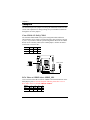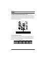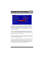
1
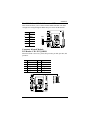
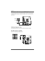
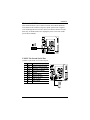
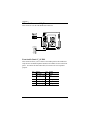
User’s Manual
P4-ITX
Mini-ITX Mainboard
PN 99-51-012801-12
Version 1.2
August 21, 2003
Copyright
Copyright by Insight Solutions Inc.. No part of this manual may be
reproduced or transmitted in any form without express written authorization
from Insight Solutions.
Trademarks
All trademarks are the property of their respective holders.
PS/2 and OS/2 are registered trademarks of IBM Corporation.
Windows 95/98/98SE/ME/2000/NT and Windows XP are registered
trademarks of Microsoft.
Award is a registered trademark of Award Software Inc.
Data protection
All data should be backed-up prior to the installation of any drive unit or
storage peripheral. Insight Solutions will not be responsible for any loss of
data resulting from the use, disuse or misuse of this or any other Insight
Solutions product.
No Warranty
Insight Solutions has made every effort to ensure the accuracy of the content
of this manual. However, it is possible that it may contain technical
inaccuracies or typographical or other errors. Our products are under
continual improvement and we reserve the right to make changes without
notice. Insight Solutions will assume no liability for any inaccuracy found in
this publication, nor for damages, direct, indirect, incidental, consequential
or otherwise, that may result from such an inaccuracy, including without
limitation loss of data or profits.
Insight Solutions provides this manual “as is”, and does not issue a warranty
of any kind, express or implied, including without limitation implied
warranties of merchantability or fitness for a particular purpose.
The information provided in this manual is subject to change without notice.
Insight Solutions reserves the right to alter product designs, layouts or
drivers without notification.
ii
FCC-B Radio Frequency Interference Statement
This equipment has been tested and found to comply with the limits for a
class B digital device, pursuant to part 15 of the FCC rules. These limits are
designed to provide reasonable protection against harmful interference when
the equipment is operated in a commercial environment. This equipment
generates, uses and can radiate radio frequency energy and, if not installed
and used in accordance with the instruction manual, may cause harmful
interference to radio communications. Operation of this equipment in a
residential area is likely to cause harmful interference, in which case the user
will be required to correct the interference at his own expense.
Notice 1
The changes or modifications not expressly approved by the party
responsible for compliance could void the user’s authority to operate the
equipment.
Notice 2
Shielded interface cables and A.C. power cord, if any, must be used in order
to comply with the emission limits.
iii
Safety Instructions
1. Always read the safety instructions carefully.
2. Keep this User’s Manual for future reference.
3. Keep this equipment away from humidity.
4. Lay this equipment on a reliable flat surface before setting it up.
5. The openings on the enclosure are for air convection hence protects the
equipment from overheating. DO NOT COVER THE OPENINGS.
6. Make sure the voltage of the power source and adjust properly 110/220V
before connecting the equipment to the power inlet.
7. Place the power cord in such a way that people cannot step on it. Do not
place anything over the power cord.
8. Always unplug the power cord before inserting any add-on card or
module.
9. All cautions and warnings on the equipment should be noted.
10. Never pour any liquid into the opening. Liquid can cause damage or
electrical shock.
11. If any of the following situations arises, get the equipment checked by a
service personnel:
• The power cord or plug is damaged
• Liquid has penetrated into the equipment
• The equipment has been exposed to moisture
• The equipment has not work well or you can not get it work according
to User’s Manual.
• The equipment has dropped and damaged
• If the equipment has obvious sign of breakage
12. DO NOT LEAVE THIS EQUIPMENT IN AN ENVIRONMENT
UNCONDITIONED, STORAGE TEMPERATURE ABOVE 60 C
(140 F), IT MAY DAMAGE THE EQUIPMENT.
0
0
CAUTION: Explosion or serious damage may occur if the battery is
incorrectly replaced. Replace only with the same or equivalent type
recommended by the manufacturer.
iv
Box Contents
• 1 x Insight Solutions Mainboard
• 1 x User’s Manual
• 1 x Floppy Ribbon Cable
• 1 x ATA-33/66/100/133 IDE Ribbon Cable
• 1 x IO Bracket
• 1 x Driver Utilities CD
v
Table of Contents
Chapter 1: Specifications ........................................1-1
Mainboard Specifications ..........................................................1-2
Mainboard Layout .....................................................................1-4
Back Panel Ports ......................................................................1-5
Slots ..........................................................................................1-5
Onboard Connectors and Jumpers ...........................................1-6
Chapter 2: Installation..............................................2-1
CPU Installation ........................................................................2-2
Memory Module Installation ......................................................2-5
Connecting the Power Supply...................................................2-7
Back Panel Ports ......................................................................2-8
Connectors..............................................................................2-12
Jumpers ..................................................................................2-20
Slots ........................................................................................2-22
Chapter 3: BIOS Setup .............................................3-1
Entering Setup ..........................................................................3-2
Control Keys .............................................................................3-2
Getting Help ..............................................................................3-3
The Main Menu .........................................................................3-4
Standard CMOS Features ........................................................3-6
Advanced BIOS Features .........................................................3-8
Advanced Chipset Features....................................................3-12
Integrated Peripherals.............................................................3-15
Power Management Setup .....................................................3-19
PnP / PCI Configurations ........................................................3-24
PC Health Status ....................................................................3-26
Frequency Control ..................................................................3-27
Load Fail-Safe Defaults ..........................................................3-29
Load Optimized Defaults.........................................................3-30
Set Supervisor / User Password .............................................3-31
Save & Exit Setup ...................................................................3-33
Exit Without Saving .................................................................3-34
Chapter 4: Driver Installation ..................................4-1
Driver Utilities CD Content ........................................................4-2
vi
Appendix A: Smart 5.1 ............................................ A-1
Intelligent 6-Channel Audio ...................................................... A-2
Hyper-Threading Technology .................................................. A-9
vii
Chapter
1
Specifications
The ultra-compact and highly intergrated Insight
Solutions P4-ITX Mini-ITX Mainboard is the
smallest form factor mainboard specification
available today, developed by VIA Technologies,
Inc. as part of the company’s open industry-wide
total connectivity initiative. The mainboard enables
the creation of an exciting new generation of small,
ergonomic, innovative and affordable embedded
systems. Through high level of integration, miniITX only occupy 66% of the size of FlexATX
mainboard form factor.
This chapter includes the following sections:
Mainboard Specifications
1-2
Mainboard Layout
1-4
Back Panel Ports
1-5
Slots
1-5
Connectors / Jumpers
1-6
1-1
Chapter 1
Mainboard Specifications
CPU
• Intel® Pentium® 4, Celeron® Processor (Willamette / Northwood 478pin)
• 533 / 400 MHz Front Side Bus Support up to 3.06 GHz CPU only
Chipset
• VIA P4N266A North Bridge
• VT8235 South Bridge
Memory
• 1 x DDR266 DIMM socket (up to 1 GB)
Expansion Slots
• 1 x PCI
Graphics
• Integrated S3 ProSavage8 AGP4X graphics
Audio
• VIA VT1616, six-channel AC’97 Codec
IEEE 1394
• VIA VT6307S, IEEE 1394
LAN
• VIA VT6103 10 / 100 Base-T Ethernet PHY
IDE
• 2 x UltraDMA 133/100/66 Connector
Floppy
• 1 x FDD Connector
1-2
Specifications
Back Panel I/O Ports
• 1 x PS2 mouse port
• 1 x PS2 keyboard port
• 1 x VGA port
• 1 x S-Video port
• 1 x RCA port (used for either SPDIF or TV-out)
• 1 x Parallel
• 1 x RJ-45 LAN port
• 2 x USB 2.0/1.1 ports
• 1 x Serial port
• 3 x Audio jacks: line-out, line-in and mic-in
Onboard I/O Connectors
• 2 x USB conncetors for 4 additional USB 2.0 ports
• 1 x IEEE 1394 Port
• 1 x Front-panel Audio pin-header for Line-Out, MIC-In
• 1 x CD Audio-in connector
• 1 x Buzzer
• 1 x SM Bus connector
• 1 x SIR connector
• 1 x CIR connector (Switchable for KB / MS)
• 1 x Wake-on-LAN connector
• 3 x Fan connectors (CPU Fan / SYS Fan / Fan 3)
• 1 x Connectors for LVDS module (Optional)
• 1 x Serial port connector for second COM port
BIOS
• Award BIOS on 2/4Mbit flash memory
Form Factor
• 17 cm X 17 cm Mini-ITX (4 layers)
1-3
Chapter 1
Mainboard Layout
CIR
DIMM
Top: Mouse
Bottom: Keyboard
ATXPWR
AUX12V
CPUFAN
VGA Out
CPU Socket
FDD
Top: RJ45
Bottom: USB
IDE1 IDE2
Top: Parallel
Bottom (L): S-Video
Bottom (M): RCA/SPDIF
Bottom (R): COM1
GAME_PORT
SPDIF_SEL
WOL
COM2
CD_IN
USB 3/4
USB 5/6
N
A
SYSFAN
LVDS
CMOS
BATTERY
FAN3
Audio Jacks
F_PANEL
CLEAR_CMOS
1394
F_AUDIO
1394/EN1
PCI1
Back Panel
Parallel (LPT1)
RJ45
PS2_MS
Line-In
Line-Out
Microphone
PS2_KB
VGA Out
USB
S-Video
RCA / SPDIF
1-4
COM1
Specifications
Back Panel Ports
Port
Audio Jacks
COM1
LPT1
PS2-MS
PS2-KB
RCA_JACK
RJ45
S-VIDEO
USB 1-2
VGA Out
Description
Line-Out, Line-In, Microphone
Serial port
Parallel port
PS2 mouse port
PS2 keyboard port
RCA Video or SPDIF jack
10/100 NIC port
S-Video Port
Universal Serial Bus ports 1 - 2
VGA out port
Page
2-11
2-11
2-10
2-8
2-8
2-9
2-9
2-9
2-9
2-9
Description
Memory module slot
Expansion card slot
Page
2-5
2-22
Slots
Slot
DIMM1
PCI1
1-5
Chapter 1
Onboard Connectors and Jumpers
Connecter/Jumper
1394
1394/EN
ATXPWR
CD_IN
CLEAR_CMOS
COM2
F_AUDIO
F_PANEL
Fans
FDD
FIR
IDE 1-2
KBMS
LVDS
SM_Bus
SPDIF_SEL
USB 3/4 - 5/6
WOL
Description
1394 Port Connector
Enable 1394 Port on Back panel
ATX power cable connector
Onboard CD audio cable connector
Jumper to reset CMOS settings to default
Second serial port connector
Front Audio Panel connector
Case connectors
CPU Fan / SYS Fans / Fan 3
Floppy disk drive connector
Fast IrDA Infrared Module connector
IDE hard disk drive connectors
CIR/PS2(EXT_KBMS) connector
LVDS Connector
SM Bus connector
Sony Philips Digital Interface jumper
Universal Serial Bus connectors 3 - 6
Wake On LAN connector
1-6
Page
2-16
2-21
2-7
2-18
2-20
2-17
2-18
2-13
2-13
2-14
2-13
2-12
2-15
2-19
2-16
2-20
2-16
2-17
Chapter
2
Installation
This chapter provides you with information about
hardware setup procedures. While installing the
mainboard, carefully hold the components and
closely follow the installation procedures. Some
components may be damaged if they are installed
incorrectly.
It is recommended to use a grounded wrist strap
before handling computer components. Static electricity can damage some components.
This chapter includes the following sections:
CPU Installation
2-2
Memory Module Installation
2-5
Connecting the Power Supply
2-7
Back Panel Ports
2-8
Connectors
2-12
Jumpers
2-20
Slots
2-22
2-1
Chapter 2
CPU Installation
The mainboard supports the Intel Pentium 4 Willamette/Northwood and
Celeron processors in the 478 pin package (PGA478). When installing the
CPU, ensure the CPU has a large-size heatsink and a cooling fan
attached on the top to prevent overheating. If the heatsink and cooling
fan are not included with the CPU, contact your dealer to purchase and
install them before turning on the computer.
®
®
®
CPU Installation
1. Pull the lever sideways away from
the socket. Then raise the lever up
to a 90-degree angle.
2. Look for the dot/cut edge. The dot/
cut edge should point towards the
lever pivot. The CPU will only fit
in the correct orientation.
3. Hold the CPU down firmly, then
close the lever shut to complete the
installation.
2-2
Installation
CPU Fan Installation
As processor technology pushes to faster speeds and higher performance,
thermal management becomes increasingly important. To dissipate heat, you
MUST attach the CPU cooling fan and heatsink on top of the CPU.
Overheating will cause serious damage to the CPU and system. Ensure the
cooling fan and heatsink work properly to protect the CPU from overheating.
Follow the instructions below to install the Heatsink/Fan:
1. Locate the CPU and its retention
mechanism on the mainboard.
2. Position the heatsink and fan
onto the retention mechanism.
3. Mount the fan on top of the
heatsink. Press down the fan
firmly until its four clips become
wedged in the holes of the retention mechanism.
2-3
Chapter 2
4. Press the two levers down to
secure the fan. Each lever can
be pressed down in only ONE
direction.
5. Connect the fan power cable
from the mounted fan to the 3pin fan power connector on the
mainboard.
2-4
Installation
Memory Module Installation
The Insight Solutions P4-ITX Mini-ITX Mainboard provides one DIMM
slot for DDR SDRAM memory modules.
N
A
You can install either single sided or double sided 184-pin DDR DIMM
modules into the DDR DIMM sockets, depending on your requirements.
Differing from SDR DIMM, DDR DIMM modules have only one notch on
the center of the module. The number of pins on either side of the breaks are
also different. The memory modules will only fit if placed in the correct orientation.
2-5
Chapter 2
SDRAM Module Installation Procedures.
1. The DDR DIMM module has only one
notch on the center.
2. Align the SDRAM module with the
corresponding notches on the DIMM
slot. The modules will only fit if placed
in the correct position.
3. With both hands, press the SDRAM
module down into the DIMM slot so that
the white retaining latches rotate up and
secure the module in place (see picture
below).
Available SDRAM Configurations
Refer to the table below for available SDRAM configurations on the mainboard.
Slot
Memory Module
Total Memory
DIMM
(Bank 0 & 1)
64MB, 128MB, 256MB, 512MB, 1GB
64 MB - 1 GB
Maximum System Memory Supported
2-6
64 MB - 1 GB
Installation
Connecting the Power Supply
The mainboard requires an ATX power supply for powering the system.
Before inserting the power supply connector, always make sure that all components are installed properly to ensure that no damage will be caused.
ATX 20-Pin Power Connector: ATXPWR
This connector is for the ATX power supply. To connect to the ATX power
supply, make sure the plugs of the power supply are inserted in the correct
orientation and the pins are properly aligned. Then, push down the plugs
firmly into the connector.
AUX 12-Volt Power Connector: AUX12V
This 12V power connector is used to provide power to the CPU.
ATXPWR
AUX12V
N
A
ATXPWR Pins
Pin
1
2
3
4
5
6
7
8
9
10
Signal
3.3V
3.3V
GND
5V
GND
5V
GND
PW_OK
5V_SB
12V
Pin
11
12
13
14
15
16
17
18
19
20
Signal
3.3V
-12V
GND
PS_ON
GND
GND
GND
-5V
5V
5V
AUX12V Pins
Pin
1
2
3
4
2-7
Signal
GND
GND
12V
12V
Chapter 2
Back Panel Ports
The back panel has the following ports:
Parallel (LPT1)
RJ45
PS2_MS
Line-In
Line-Out
Microphone
PS2_KB
VGA Out
USB
S-Video
RCA / SPDIF
COM1
Mouse Port: PS2_MS
The mainboard provides a standard PS/2 mouse connector for attaching a
PS/2 mouse. You can plug a PS/2 mouse directly into this connector. The
connector location and pin assignments are as follows.
Pin
1
4
3
2
3
2
1
4
PS2 Mouse (6-pin female)
5
6
6
5
Signal
Mouse DATA
NC
GND
VCC
Mouse Clock
NC
Description
Mouse data
No connection
Ground
+5V
Mouse clock
No connection
Keyboard Port: PS2_KB
The mainboard provides a standard PS/2 keyboard connector for attaching a
PS/2 keyboard. You can plug a PS/2 keyboard directly into this connector.
Pin
1
6
5
2
4
3
3
2
1
4
PS2 Keyboard (6-pin female)
5
6
Signal
Mouse DATA
NC
GND
VCC
Mouse Clock
NC
2-8
Description
Mouse data
No connection
Ground
+5V
Mouse clock
No connection
Installation
VGA Out
A DB-15 pin female connector that connects to a
VGA monitor.
RJ45 10/100 NIC Port
The mainboard provides one standard RJ-45 port for
connection to the Local Area Network (LAN). You
can connect a network cable to the LAN port.
USB Ports
The mainboard provides 2 USB 2.0/1.1 ports (plus 1 pin-header for up to 2
additional USB 2.0/1.1 ports). USB-compatible devices can be plugged
directly into these ports.
Pin
1
2
3
4
Signal
VCC
-DATA
+DATA
GND
Description
+5V
Negative Data Channel
Positive Data Channel
Ground
S-Video Port
This port allows S-Video output in NTSC and PAL
modes.
RCA Video or S/PDIF Port
This dual function port may be used either as a RCA
Video port or as a S/PDIF port. See SPDIF_SEL in the
Jumpers section for more details.
2-9
1 2 3 4
Chapter 2
Parallel Port: LPT1
The mainboard provides a 25-pin female connector for LPT (parallel port).
A parallel port is a standard printer port that supports Enhanced Parallel Port
(EPP) and Extended Capabilities Parallel Port (ECP) modes.
13
1
25
Pin
1
2
3
4
5
6
7
8
9
10
11
12
13
14
15
16
17
18
19
20
21
22
23
24
25
Signal
STROBE
DATA0
DATA1
DATA2
DATA3
DATA4
DATA5
DATA6
DATA7
ACK#
BUSY
PE
SELECT
AUTOFEED#
ERR#
INIT#
SLIN#
GND
GND
GND
GND
GND
GND
GND
GND
14
Description
Strobe
Data 0
Data 1
Data 2
Data 3
Data 4
Data 5
Data 6
Data 7
Acknowledge
Busy
Paper End
Select
Automatic Feed
Error
Initialize Printer
Select In
Ground
Ground
Ground
Ground
Ground
Ground
Ground
Ground
2-10
Installation
Serial Ports: COM1, COM2
The mainboard offers two 9-pin male Serial Port connectors (COM 1 and
COM 2) . You can attach a serial mouse or other serial devices directly to
these ports.
1
5
6
9
9-Pin Serial Port
Pin
1
2
3
4
5
6
7
8
9
Signal
DCD
SIN
SOUT
DTR
GND
DSR
RTS
CTS
RI
Description
Data Carry Detect
Serial In or Receive Data
Serial Out or Transmit Data
Data Terminal Ready
Ground
Data Set Ready
Request To Send
Clear To Send
Ring Indicate
Audio Jacks: Line-In, Line-Out, Microphone
Jack
Line-In
Line-Out
Mic
2-Channel
Line in
Line out
Microphone
The Line-Out jack is for connecting to
external speakers or headphones.
The Line-In jack is for connecting to an
external audio device such as a CD
player, tape player, etc...
6-Channel
Rear (Left / Right)
Front (Left / Right)
Center / Subwoofer
2-Channel
6-Channel
Line-In
Rear (L/R)
Line-Out
Front (L/R)
Microphone
Center/Sub
The Mic jack is for connecting to a
microphone.
When 6-channel applications are used, all three jacks become output connectors with Smart 5.1 (See Appendix A) In order for the 6-channel audio to
function, the operating system and multimedia application must be properly
configured. Please note that Windows 98 only supports 4-channel audio.
2-11
Chapter 2
Connectors
Hard Disk Connectors: IDE1 & IDE2
The mainboard has a 32-bit Enhanced PCI IDE and Ultra DMA 66/100 controller that provides PIO mode 0~4, Bus Master, and Ultra DMA 66/100
functions. You can connect up to four hard disk drive, CD-ROM, LS-120
and other devices. These connectors utilize the provided IDE hard disk
cable.
N
A
IDE1
IDE2
IDE1 (Primary IDE Connector)
The first hard drive should always be connected to IDE1. IDE1 can connect
a Master and a Slave drive. You must configure the second hard drive to
Slave mode by setting the jumper accordingly.
IDE2 (Secondary IDE Connector)
IDE2 can also connect a Master and a Slave drive.
If you install two hard disks on a single cable, you must set the jumper on the
second hard disk drive to slave mode. Please refer to the hard disk documentation supplied by hard disk vendor for the jumper settings.
2-12
Installation
Fan Power Connectors: CPUFAN SYSFAN & FAN 3
The CPUFAN (CPU fan) and SYSFAN (chassis fan) both run on +12V to
maintain system cooling. When connecting the wire to the connectors,
always be aware that the red wire is the Positive and should be connected to
the +12V. The black wire is Ground and should be connected to GND. Both
CPU and chasis fan connectors have sensors to detect fan speed. FAN3 is an
additional FAN connector.
CPUFAN
N
A
SYSFAN
FAN3
Case Connectors: F_PANEL
The F_PANEL connector block allows you to connect to the power switch,
reset switch, power LED, HDD LED, SLED and the Speaker on the case.
Pin
1
3
5
7
9
11
13
15
Signal
PWR LED+
PWR LED+
PWR LEDSPEAKER+
NC
NC
SPEAKERNC
Pin
2
4
6
8
10
12
14
16
Signal
HDD LED+
HDD LEDPW_BN+
PW_BNRESET+
RESETSLED+
SLED-
2-13
N
A
2
16
1
15
Chapter 2
Power Switch
Connect to a 2-pin push button switch. Pressing this button will turn the system power on or off.
Reset Switch
The Reset Switch is used to reboot the system rather than turning the power
ON/OFF. Avoid rebooting while the HDD is working. You can connect the
Reset Switch from the system case to this pin.
Power LED
The LED is lit when the system is power on. If the system is in S1 (POS Power On Suspend) or S3 (STR - Suspend To RAM) state, the LED will
blink.
HDD LED
HDD LED shows the activity of a hard disk drive. Avoid turning the power
off while HDD LED is lit. Connect the HDD LED from the system case to
this pin.
SLED
The SLED is lit when the system is in the S1 (POS - Power On Suspend)
state.
Speaker
The speaker from the system case is connected to this pin.
Floppy Disk Drive Connector: FDD
The floppy disk drive connector supports 360K, 720K, 1.2M. 1.44M, and
2.88M floppy disk types.
N
A
FDD
2-14
Installation
Fast IrDA Infrared Module Connector: FIR
This connector allows you to connect an IrDA Infrared module. You must
configure the setting through the BIOS setup to activate the IR function.
Pin
Signal
1
VCC
2
IRRX1
3
IRRX
4
GND
5
IRTX
FIR
1
N
A
5
Consumer Infrared Module,
PS2 Header: CIR / EXT_KBMS
When the header is not in use, please short pin 3&5, pin 4&6, pin 7&9, and
pin 8&10.
Pin
1
3
5
7
9
Signal
+5V
KB_CLK
EXT_KBCLK
MS_CLK
EXT_MSCLK
Pin
2
4
6
8
10
Signal
GND
KB_DATA
EXT_KBDATA
MS_DATA
EXT_MSDATA
N
A
2-15
Chapter 2
Universal Serial Bus Connectors: USB 3/4, 5/6
The mainboard provides 2 front USB pin-header connectors, allowing up to
4 additional USB 2.0 ports. USB 2-port modules can be connected to these
pin-headers.
USB 3/4
USB 5/6
N
A
1394
1394 Port Connector: 1394
The mainboard provides a connector to attach an external 1394 port.
SM_Bus Connector: SM Bus
This is for connecting a SM Bus device.
Pin
Signal
1
SMBCK
2
SMBDT
3
GND
SM Bus
1
3
N
2-16
A
Installation
Wake-on LAN: WOL
This connector allows you to connect a network card with the Wake-On
LAN function. The connector will power up the system when a signal is
received through the network card. Please note that the function of ACPI
WOL may be disabled when users unplug the power cord or turn off the
power button manually.
N
A
WOL
COM2: The Second Serial Port
COM2 is a pin header for second serial port.
Pin
1
2
3
4
5
6
7
8
9
Signal
DCD
SIN
SOUT
DTR
GND
DSR
RTS
CTS
RI
Description
Data Carry Detect
Serial In or Receive Data
Serial Out or Transmit Data
Data Terminal Ready
Ground
Data Set Ready
Request To Send
Clear To Send
Ring Indicate
N
2
1
9
COM2
2-17
A
Chapter 2
CD Audio Connector: CD_IN
This connector is for the CD-ROM audio connector.
CD_IN
N
A
F-AUDIO
10
9
2
1
Front Audio Panel: F_AUDIO
This connector allows you to connect a front audio panel to the mainboard.
Only the line-out and microphone functions are available for use on the front
panel. To connect the front audio cable, first remove the two red plastic
jumpers.
Pin
1
3
5
7
9
Signal
FRN_MIC
AUD_MIC_BIA
S
LINE_OUT_R
NC
LINE_OUT_L
Pin
2
4
Signal
AGND
+5V
6
8
10
Next_R
Keypin
Next_L
2-18
Installation
LVDS Connector: LVDS
This connector is for the LVDS output connection.
LVDS
N
A
2-19
Chapter 2
Jumpers
The mainboard provides jumpers for setting the mainboard’s functions. This
section will explain how to change settings for your mainboard’s functions
through the use of the jumpers.
Clear CMOS: CLEAR_CMOS
The onboard CMOS RAM stores system configuration data and has an
onboard battery power supply. The long-life battery has a lifetime of at least
5 years. If you want to clear the system configuration data from the CMOS
RAM, use the CLEAR_CMOS (Clear CMOS jumper). Follow the instructions below to clear the data:
CMOS
Clear
Keep
1
ON
OFF
1
2
3
4
2
ON
ON
3
OFF
ON
CLEAR_CMOS
1
SPDIF_SEL
N
A
2
3
RCA Video or S/PDIF Select: SPDIF_SEL
Users can select either RCA Video or S/PDIF as the enabled function on the
dual-purpose port. For TV-out composite function, please short 1-2. For
RCA Video, short 3-4 (default) CHECK TABLE .
1
2
3
4
RCA
Setting
ON
ON
OFF
OFF
SPDIF
OFF
OFF
ON
ON
2-20
Installation
Enable 1394 Port on Back Panel: 1394/EN
This jumper allows you to enable/disable the 1394 port on the back panel.l
Enable
Disable
1
ON
OFF
2
ON
ON
3
OFF
ON
3
N
A
2-21
2
1
Chapter 2
Slots
Peripheral Component Interconnect: PCI
The PCI slot allows you to insert PCI expansion card. When adding or
removing expansion cards, make sure that you unplug the power supply first.
Meanwhile, read the documentation for the expansion card to make any necessary hardware or software settings for the expansion card, such as jumpers,
switches or BIOS configuration.
N
A
PCI Interrupt Request Routing
The IRQ, abbreviation of interrupt request line and pronounced I-R-Q, are
hardware lines over which devices can send interrupt signals to the microprocessor. The “PCI & LAN” IRQ pins are typically connected to the PCI
bus INT A# ~ INT D# pins as follows:
Order 1
Order 2
Order 3
Order 4
PCI Slot
INT B#
INT C#
INT D#
INT A#
IEEE 1394
INT B#
2-22
Chapter
3
BIOS Setup
This chapter gives you detailed explaination of each
BIOS setup functions.
This chapter includes the following sections:
Entering Setup
3-2
Control Keys
3-2
Gettings Help
3-3
The Main Menu
3-4
Standard CMOS Features
3-6
Advanced BIOS Features
3-8
Advanced Chipset Features
3-12
Integrated Peripherals
3-15
Power Management Setup
3-19
PnP / PCI Configurations
3-24
PC Health Status
3-26
Frequency Control
3-27
Load Fail-Safe Defaults
3-29
Load Optimized Defaults
3-30
Set Supervisor / User Password
3-31
Save & Exit Setup
3-33
Exit Without Saving
3-34
3-1
Chapter 3
Entering Setup
Power on the computer and press Delete straight away to enter the BIOS
setup menu. If you missed the BIOS setup entry point, you may restart the
system and try again.
Control Keys
Keys
Up Arrow
Down Arrow
Left Arrow
Right Arrow
Enter
Escape
Page Up / +
Page Down / F1
F5
F6
F7
F9
F10
Description
Move to the previous item
Move to the next item
Move to the item in the left side
Move to the item in the right side
Select the item
Jumps to the Exit menu or returns to the main menu
from a submenu
Increase the numeric value or make changes
Decrease the numeric value or make changes
General help, only for Status Page Setup Menu and
Option Page Setup Menu
Restore the previous CMOS value from CMOS, only
for Option Page Setup Menu
Load the default CMOS value from Fail-Safe default
table, only for Option Page Setup Menu
Load Optimized defaults
Jumps to the Main Menu
Save all the CMOS changes and exit
3-2
BIOS Setup
Getting Help
Main Menu
The main menu displays all BIOS setup categories. Use the control keys
Up/Down Arrow Keys to select any item/sub-menu. Description of the
selected/highlighted category is displayed at the bottom of the screen.
Sub-Menu
If you find a right pointer symbol (as shown in
IDE Primary Master
the right view) appears on the left of certain
IDE Primary Slave
IDE Secondary Maste
fields, this means a sub-menu is available. The
IDE Secondary Slave
sub-menu contains additional options. You
can use control keys Up/Down Arrow
Keys to highlight the field and press Enter to enter the sub-menu. To
return from the sub-menu press Esc.
General Help: F1
The BIOS setup program provides a General Help screen. You can call up
this screen from any menu/sub-menu by pressing F1. The help screen
displays the keys for use and navigate the BIOS setup. Press Esc to exit the
help screen.
3-3
Chapter 3
The Main Menu
The Main Menu contains twelve setup functions and two exit choices. Use
arrow keys to select the items and press Enter to accept or enter the submenu.
Standard CMOS Features
Use this menu to set basic system configurations.
Advanced BIOS Features
Use this menu to set the advanced features available on your system.
Advanced Chipset Features
Use this menu to set chipset specific features and optimize system
performance.
Integrated Peripherals
Use this menu to set onboard peripherals features.
Power Management Setup
Use this menu to set onboard power management functions.
PnP/PCI Configurations
Use this menu to set the PnP and PCI configurations.
PC Health Status
This menu shows the PC health status.
3-4
BIOS Setup
Frequency/Voltage Control
Use this menu to set the system frequency and voltage control.
Load Fail-Safe Defaults
Use this menu option to load the BIOS default settings for minimal and
stable system operations.
Load Optimized Defaults
Use this menu option to load BIOS default settings for optimal and high
performance system operations.
Set Supervisor Password
Use this menu option to set the BIOS supervisor password.
Set User Password
Use this menu option to set the BIOS user password.
Save & Exit Setup
Save BIOS setting changes and exit setup.
Exit Without Saving
Abandon all BIOS setting changes and exit setup.
3-5
Chapter 3
Standard CMOS Features
Date
The date format is <Day><Month><Date><Year>.
Day - day of the week, for example Friday. Read-only.
Month - the month from Jan to Dec.
Date - the date from 1 to 31.
Year - the year, range from 1999 to 2098.
Time
The time format is <Hour><Minute><Second>.
Drive A/B
Set the type of floppy drive installed. Settings: None, 360K (5.25 in.), 1.2M
(5.25 in.), 720K (3.5 in.), 1.44M (3.5 in.), 2.88M (3.5 in.)
Halt On
Determine the system behaviour if an error is detected at boot. Settings are:
All Errors
No Errors
All, But Keyboard
All, But Diskette
All, But Disk/Key
System halts when any error is detected.
System does not halt for any error.
System halts for all non-key errors.
System halts for all non-disk errors.
System halts for all non-key and non-disk errors.
3-6
BIOS Setup
IDE Primary Master/Slave, Secondary Master/Slave
Press Enter to enter the sub-menu and the following screen appears:
The specifications of your drive must match with the drive table. The hard
disk will not work properly if you enter improper information for this
category. Select Auto whenever possible. If you select Manual, make sure the
information provided is from your hard disk vendor or system manufacturer.
IDE <Primary
Master>
Access Mode
Capacity
Cylinder
Head
Precomp
Landing Zone
Sector
PIO Mode
Ultra DMA Mode
The name of this menu item will match the
name of the menu. The settings are None,
Auto, Manual.
The settings are CHS, LBA, Large, Auto.
The formatted size of the storage device.
Number of cylinders.
Number of heads.
Write precompensation.
Cylinder location of the landing zone.
Number of sectors.
The settings are Mode 0/1/2/3/4, Auto.
The settings are Disabled and Auto.
3-7
Chapter 3
Advanced BIOS Features
Virus Warning
Set the Virus Warning feature for IDE Hard Disk boot sector protection. If
the function is enabled, any attempt to write data into this area will cause a
beep and warning message display on screen. Settings: Disabled and Enabled
CPU Hyper-Threading
If the function is enabled, the processor is able to run multiple threads
simultaneously. See Appendix A-9 for more detailed information. Settings:
Disabled and Enabled.
CPU L2 Cache ECC Checking
Set the ECC (Error-Correcting Code) feature for Level 2 cache. Facilitates
error detection/correction when data passes through Level 2 cache. Settings:
Enabled and Disabled
Quick Power On Self Test
Shorten Power On Self Test (POST) cycle and enable shorter bootup time.
Allow BIOS to skip some check items during POST. Settings: Enabled and
Disabled
3-8
BIOS Setup
First/Second/Third Boot Device
Set the boot device sequence as BIOS attempts to load the disk operating
system. The settings are:
Floppy
LS120
HDD-0
SCSI
CD-ROM
HDD-1
HDD-2
HDD-3
ZIP100
USB-FDD
USB-ZIP
USB-CDROM
USB-HDD
LAN
Disabled
The system will boot from floppy drive.
The system will boot from LS-120 drive.
The system will boot from first HDD.
The system will boot from SCSI.
The system will boot from CD-ROM.
The system will boot from second HDD.
The system will boot from third HDD.
The system will boot from fourth HDD.
The system will boot from ATAPI ZIP drive.
The system will boot from USB floppy drive.
The system will boot from USB ZIP drive.
The system will boot from USB CDROM.
The system will boot from USB HDD.
The system will boot from network drive.
Disable this sequence.
Boot Other Device
Enable the system to boot from other devices if the system fails to boot from
the First/Second/Third boot device. Settings: Enabled and Disabled
Swap Floppy Drive
If the system has two floppy drives, choose Enabled to assign physical drive
B to logical drive A and vice versa. Settings: Enabled and Disabled
Boot Up Floppy Seek
Set floppy seek during POST, BIOS will determine whether the floppy is 40
or 80 tracks. Settings: Enabled and Disabled
3-9
Chapter 3
Boot Up NumLock Status
Set the NumLock status when the system is powered on. On will turn key
pad into number keys, and Off will turn key pad into arrow keys. Settings: On
and Off
Typematic Rate Setting
When Disabled, the following two items (Typematic Rate and Typematic
Delay) are irrelevant. Keystrokes repeat at a rate determined by the keyboard
controller in your system. When Enabled, you can select a typematic rate and
typematic delay. Settings: Enabled and Disabled
Typematic Rate (Chars/Sec)
When Typematic Rate Setting is enabled, this item allows you to set the rate
(characters/second) at which the keys are accelerated. Settings: 6, 8, 10, 12,
15, 20, 24 and 30
Typematic Delay (Msec)
When Typematic Rate Setting is enabled, this item allows you to select the
delay between when the key was first pressed and when the acceleration
begins. Settings: 250, 500, 750 and 1000
Security Option
If you have set a password, select whether the password is required every
time the System boots, or only when you enter Setup. Settings are described
below:
Setup
System
The password prompt appears only when end users
try to run Setup.
A password prompt appears every time when the
computer is powered on or when end users try to
run Setup.
MPS Version Control For OS
Choose which MPS version control for OS. Settings: 1.1 and 1.4.
3-10
BIOS Setup
Display Full Screen Logo
Show full screen logo during BIOS bootup process. Settings: Enabled and
Disabled
Show Summary Information
Settings: Enabled and Disabled
Display Small Logo
Show small energy star logo during BIOS bootup process. Settings: Enabled
and Disabled
3-11
Chapter 3
Advanced Chipset Features
The Advanced Chipset Features menu is used for optimizing the chipset
functions.
WARNING: Do not change these settings unless you are familiar with the chipset.
AGP Aperture Size
This setting controls how much memory space can be allocated to AGP for
video purposes. The aperture is a portion of the PCI memory address range
dedicated to graphics memory address space. Host cycles that hit the
aperture range are forwarded to the AGP without any translation. Settings:
4MB, 8MB, 16MB, 32MB, 64MB, 128MB, and 256MB
AGP Mode
This mainboard supports the AGP 4x interface. When the AGP 4x video
card is used, it can transfer video data at 1066MB/s. AGP 4x is backwardcompatible, leave the default 4x mode on if unsure. When set to 1x mode,
the maximum transfer rate it at 266MB/s, and 2x mode transfers data at
533MB/s. AGP8x mode can be detected automatically once you plug in the
AGP8x card. Settings: 4X, 2X and 1X.
3-12
BIOS Setup
AGP Driving Control
The setting is used to adjust AGP driving force. Selecting Manual allows
you to type a AGP driving force in AGP Driving Value. It is strongly suggested to select Auto to avoid causing any system error. Settings: Auto and
Manual.
CPU to PCI POST Write
When Enabled, CPU can write up to four words of data to the PCI write
buffer before CPU must wait for PCI bus cycle to finish. If Disabled, CPU
must wait after each write cycle until PCI bus signals that it is ready to
receive more data. Settings: Enabled and Disabled
Select Display Device
This setting refers to the type of display being used with the system.
Settings: CRT, TV, CRT + TV, LCD and CRT + LCD
TV Type
This setting refers to the type of TV signal to be used when a TV is
connected to the TV-out. Settings: NTSC, PAL and PALM
TV_Connector
This setting refers to the type of TV connector being used when a TV is
connected to the TV-out. Settings: CVBES, S-Video 0, R/G/B, Cr/Y/Cb, SDTV-R/
G/B, SDTV-Pr/Y/Pb and S-Video 1.
Panel Select
This setting refers to the native resolution of the display being used with the
system. Settings: 1024x768, 800x600 and 640x480
VGA Share Memory Size
This setting refers to the VGA share memory size. Settings: 8M, 16M and
32M.
3-13
Chapter 3
FB Address Conversion
Set the Frame Buffer address conversion mechanism. This feature optimizes
MA table for VGA frame buffer accesses according to DRAM page size in
use. It is expected to improve VGA performance. Settings: Enabled and
Disabled.
FB Page Close Prediction
Set the Frame Buffer Page Close Prediction function. This feature
automatically closes those frame-buffer DRAM pages no longer needed. It is
expected to improve DRAM related performance. Settings: Enabled and
Disabled.
3-14
BIOS Setup
Integrated Peripherals
Onboard IDE Channel 1/2
The integrated peripheral controller contains an IDE interface with support
for two IDE channels. Choose Enabled to activate each channel separately.
Settings: Enabled and Disabled
IDE Prefetch Mode
This allows your hard disk controller to use the fast block mode to transfer
data to and from the hard disk drive. Block mode is also called block
transfer, multiple commands or multiple sector read/write. Enabled enables
IDE controller to use block mode; Disabled allows the controller to use
standard mode. Settings: Enabled and Disabled
Display Card Priority
This setting specifies which VGA card is your primary graphics adapter.
Settings: PCI Slot and AGP
Onboard Lan Boot ROM
Enable Onboard Lan Boot ROM for DOS and Windows. Settings: Enabled
and Disabled.
3-15
Chapter 3
AC97 Audio
allows the mainboard to detect whether an audio device is used. If the
device is detected, the onboard VIA AC’97 (Audio Codec’97) controller will
be enabled; if not, it is disabled. Disable the controller if you want to use
other controller cards to connect to an audio device. Settings: Auto and
Auto
Disabled
VIA OnChip LAN
This setting allows you to make VIA OnChip LAN enabled or disabled.
Settings: Enabled and Disabled
USB Keyboard Support
Enable USB Keyboard Support for DOS and Windows. Settings: Enabled
and Disabled
3-16
BIOS Setup
SuperIO Device
Press Enter to enter the sub-menu and the following screen appears:
Onboard FDC Controller
Enable the onboard floppy controller. Select Enabled when you have
installed a floppy disk drive. Settings: Enabled and Disabled
Onboard Serial Port 1/2
Set the base I/O port address and IRQ for the onboard serial port A/serial
port B. Selecting Auto allows BIOS to automatically determine the
correct base I/O port address. Settings: Disabled, 3F8/IRQ4, 2F8/IRQ3, 3E8/
IRQ4, 2E8/IRQ3 and Auto
Onboard Parallel Port
This specifies the I/O port address and IRQ of the onboard parallel port.
Settings: Disabled, 378/IRQ7, 278/IRQ5 and 3BC/IRQ7
3-17
Chapter 3
Parallel Mode
Set the parallel port mode. To operate the onboard parallel port as
Standard Parallel Port, choose SPP. To operate the onboard parallel port
in the EPP mode, choose EPP. By choosing ECP, the onboard parallel
port will operate in ECP mode. Choosing ECP + EPP will allow the
onboard parallel port to support both the ECP and EPP modes
simultaneously. Settings are:
Normal
EPP
ECP
ECP + EPP
Standard Parallel Port
Enhanced Parallel Port
Extended Capability Port
Extended Capability Port + Enhanced Parallel Port
EPP Mode Select
Select the Enhance Parallel Port mode. Settings: EPP1.9 and EPP1.7.
ECP Mode Use DMA
Select a DMA channel for the port. Settings: 1 and 3
Game Port Address
Set I./O port address for onboard game port. Settings: Disabled and 200.
Midi Port Address
Set I./O port address for onboard midi port. Settings: Disabled, 330 and
300.
Midi Port IRQ
Set an IRQ for the onboard midi port. This field is only available if midi
port is not “Disabled”. Settings: 5 and 10.
Onboard Fast IR
Enable Onboard Fast IR. Settings: Enabled and Disabled.
3-18
BIOS Setup
Power Management Setup
The Power Management Setup menu configures the system to most
effectively save energy while operating in a manner consistent with your
own style of computer use.
ACPI Suspend Type
Set the power saving mode for ACPI function. Settings are:
S1(POS)
S3(STR)
S1 & S3
S1/Power On Suspend (POS) is a low power state. In
this state, no system context (CPU or chipset) is lost
and hardware maintains all system context.
S3/Suspend To RAM (STR) is a power-down state. In
this state, power is supplied only to essential
components such as main memory and wakeupcapable devices. The system context is saved to
main memory, and context is restored from the
memory when a “wakeup” event occurs.
Depends on OS to select S1 or S3.
HDD Power Down
Set the time to power down HDD after hard disk inactivity. Settings: Disable
and 1~15 (minutes)
3-19
Chapter 3
Power Management Timer
Set the idle time before system enters power saving mode. ACPI OS such as
Windows XP will override this option. Settings: Disable and 1/2/4/6/8/10/20/30/
40 (minutes) and 1 (hour)
Video Off Option
Select whether or not to turn off the screen when system enters power saving
mode, ACPI OS such as Windows XP will override this option. Settings are:
Always On
Suspend -> Off
The screen is always on even when system
enters power saving mode.
The screen is turned off when system enters
power saving mode.
Power Off by PWRBTN
This field configures the power button function. Settings are:
Delay 4 Sec
Instant-Off
The system is turned off if power button is pressed
for more than four seconds.
The power button functions as a normal power-on/off buttton.
Run VGABIOS if S3 Resume
Select whether to run VGA BIOS if resumed from S3 state. This is only
necessary for older VGA drivers, select Auto if in doubt. Settings: Auto, Yes
and No
AC Loss Auto restart
The field defines how the system will act after an AC power loss during
system operation. Choose the system power state when the AC power is
back. Settings are:
Off
On
Keep the system in off state until power button is pressed.
The system automatically restarts when AC power is back.
3-20
BIOS Setup
Peripheral Activities
Press Enter to enter the sub-menu and the following screen appears:
VGA Event
Decide whether or not the power management unit should monitor VGA
activities. Settings: Off and On
LPT & COM Event
Decide whether or not the power management unit should monitor
parallel port (LPT) and serial port (COM) activities. Settings: None, LPT,
COM and LPT/COM
HDD & FDD Event
Decide whether or not the power management unit should monitor hard
disks and floppy drives activities. Settings: Off and On
PCI Master Event
Decide whether or not the power management unit should monitor PCI
master activities. Settings: Off and On
PS2KB Wakeup Select
When select Password, please press Page Up or Page Down key to
change Password, 8 characters maximum. Please note that PS2MS
Wakeup from suspend and PS2KB Wakeup from suspend will be
disabled while changing the passward. Settings: Hot key and Password
3-21
Chapter 3
PS2MS Wakeup from S3/S4/S5
This setting can be used to wakeup the system from power saving mode
through mouse. Settings: Disabled and Enabled
PS2KB Wakeup from S3/S4/S5
Select which Hot-Key to wake-up the system from power saving mode.
Settings: Disabled, Ctrl+F1, Ctrl+F2, Ctrl+F3, Ctrl+F4, Ctrl+F5, Ctrl+F6, Ctrl+F7,
Ctrl+F8, Ctrl+F9, Ctrl+F10, Ctrl+F11, Ctrl+F12, Power, Wake and Any Key
USB Resume
Decide whether or not USB devices can wake the system from suspend
state. Settings: Disabled and Enabled
PowerOn by PCI Card
Decide whether or not any PCI card can power up the system or resume
from suspend state. Such PCI cards include LAN, onboard USB ports,
etc. Settings: Disabled and Enabled
RTC Alarm Resume
The field is used to enable or disable the feature of booting up the system
on a scheduled time/date. Settings: Disabled and Enabled
Date (of Month)
The field specifies the date for RTC Alarm Resume.
Resume Time (hh:mm:ss)
The field specifies the time for RTC Alarm Resume. Format is
<hour><minute><second>.
3-22
BIOS Setup
IRQs Activities
Press Enter to enter the sub-menu and the following screen appears:
Primary INTR
Selecting On will cause the system to wake up from power saving modes
if activity is detected from any enabled IRQ channels. Settings: Off and
On
IRQ3~IRQ15
Enables or disables the monitoring of the specified IRQ line. If set to
Enabled, the activity of the specified IRQ line will prevent the system
from entering power saving modes or awaken it from power saving
modes.
Note: IRQ (Interrupt Request) lines are system resources allocated to I/O devices.
When an I/O device needs to gain attention of the operating system, it signals this
by causing an IRQ to occur. After receiving the signal, when the operating system is
ready, the system will interrupt itself and perform the service required by the IO
device.
3-23
Chapter 3
PnP/PCI Configurations
This section describes the BIOS configuration of the PCI bus system. This
section covers some very technical items and it is strongly recommended
that only experienced users should make any changes to the default settings.
PNP OS Installed
When set to Yes, BIOS will only initialize the PnP cards used for booting
(VGA, IDE, SCSI). The rest of the cards will be initialized by the PnP
operating system like Windows 95 or 98/98SE. When set to No, BIOS will
initialize all the PnP cards. Set to Yes the operating system is Plug & Play
capable. Settings: No and Yes
®
Reset Configuration Data
Normally, you leave this field Disabled. Select Enabled to reset Extended
System Configuration Data (ESCD) when you exit Setup if you have
installed a new add-on and the system reconfiguration has caused such a
serious conflict that the operating system can not boot. Settings: Enabled and
Disabled
Resource Controlled By
The BIOS can automatically configure all the boot and Plug and Play
compatible devices. Choose Auto(ESCD) if unsure, the BIOS will
automatically assign IRQ, DMA and memory base address fields. Settings:
Auto (ESCD) and Manual
3-24
BIOS Setup
IRQ Resources
The items are adjustable only when Resources Controlled By is set to Manual. Press [Enter] and you will enter the sub-menu of the items.
IRQ Resources list IRQ 3/4/5/7/9/10/11/12/14/15 for users to set each IRQ a
type depending on the type of device using the IRQ. Settings:
PCI Device
Reserved
For Plug & Play compatible devices designed for PCI
bus architecture.
The IRQ will be reserved for further request.
Assign IRQ For VGA/USB
Assign IRQ for VGA and USB devices. Settings: Disabled and Enabled
3-25
Chapter 3
PC Health Status
This section shows the status of your CPU, fan, warning for overall system
status.
Current CPU Temp, CPU Fan Speed, System Fan Speed,
+12V, +5V, +3.3V, CPU Vcore, 5VSB.
These items display the current status of all of the monitored hardware
devices/components such as CPU voltages, temperatures and all fans’
speeds.
3-26
BIOS Setup
Frequency Control
DRAM Clock
The chipset supports synchronous and asynchronous mode between host
clock and DRAM clock frequency. Settings: By SPD, 100MHz and 133MHz.
DRAM Timing
This setting determines whether DRAM timing is configured by reading the
contents of the SPD (Serial Presence Detect) EPROM on the DRAM
module. Selecting By SPD makes SDRAM CAS Latency and Bank Interleave
automatically determined by BIOS according to the configurations on the
SPD. Settings: Manual and By SPD.
SDRAM CAS Latency
Set the time between SDRAM read command and when the data actually
becomes available. Settings: 2 and 2.5.
Bank Interleave
Set the interleave mode of the SDRAM interface. Interleaving allows banks
of SDRAM to alternate their refresh and access cycles. One bank will
undergo its refresh cycle while another is being accessed. This improves performance of the SDRAM by masking the refresh time of each bank. Settings:
Disabled, 2 Bank and 4 Bank.
3-27
Chapter 3
Precharge to Active (Trp)
Set the time from DRAM precharge to active state. Settings: 2T and 3T.
Active to Precharge (Tras)
Set the time from active back to precharge state. Settings: 5T and 6T.
Active to CMD (Trcd)
Set the time from active state to command state. Settings: 2T and 3T.
DRAM Command Rate
This setting controls the DRAM command rate. Selecting 1T allows DRAM
signal controller to run at 1T (T=clock cycles) rate. Selecting 2T makes
DRAM signal controller run at 2T rate. 1T is faster than 2T. Settings: 2T
Command and 1T Command.
DRAM Burst Len
This setting allows you to set the size for DRAM Burst-Length. The bigger
the size, the faster the system addresses memory. Settings: 4 and 8.
Spread Spectrum
When the mainboard’s clock generator pulses, the extreme values (spikes) of
the pulses creates EMI (Electromagnetic Interference). The Spread Spectrum
function reduces the EMI generated by modulating the pulses so that the
spikes of the pulses are reduced to flatter curves. If you do not have any EMI
problems, leave the setting at Disabled for optimal system stability and
performance. But if you are plagued by EMI, setting to Enabled for EMI
reduction. Settings: Disabled and Enabled.
3-28
BIOS Setup
Load Fail-Safe Defaults
This option on the main menu allows users to restore all the BIOS settings to
the default Fail Safe values. These values are set by the mainboard
manufacturer to provide a minimal and stable system.
When you select Load-Fail Safe Defaults, a message as below appears:
Entering Y loads the default BIOS values that provide a minimal and stable
system configuration.
3-29
Chapter 3
Load Optimized Defaults
This option on the main menu allows users to restore all the BIOS settings to
the default Optimized values. The Optimized Defaults are the default values
also set by the mainboard manufacturer for both optimized and stable
performance of the mainboard.
When you select Load Optimized Defaults, a message as below appears:
Entering Y loads the default values that are factory settings for optimal and
stable system performance.
3-30
BIOS Setup
Set Supervisor / User Password
When you select this function, a message as below will appear on the screen:
Type the password, up to eight characters in length, and press Enter. The
password typed now will clear any previously set password from CMOS
memory. You will be prompted to confirm the password. Re-type the
password and press Enter. You may also press Esc to abort the selection
and not enter a password.
To clear a set password, just press Enter when you are prompted to enter
the password. A message will show up confirming the password will be
disabled. Once the password is disabled, the system will boot and you can
enter Setup without entering any password.
When a password has been set, you will be prompted to enter it every time
you try to enter Setup. This prevents an unauthorized person from changing
any part of your system configuration.
There are two types of passwords you can set. A Supervisor password and a
User password. When a Supervisor password is used, the user can start
BIOS Setup program and change the settings of the setup menus. When a
User password is used, the user can start the BIOS Setup program but does
not have the right to change the settings of the setup menus.
3-31
Chapter 3
Additionally, when a password is enabled, you can also have BIOS to
request a password each time the system is booted. This would prevent
unauthorized use of your computer. The setting to determine when the
password prompt is required is the Security Option of the Advanced BIOS
Features menu. If the Security Option is set to System, the password is
required both at boot and at entry to Setup. If set to Setup, password prompt
only occurs when trying to enter Setup.
3-32
BIOS Setup
Save & Exit Setup
When you want to quit the Setup menu, you can select this option to save the
changes and quit. A message as below will appear on the screen:
Entering Y will allow you to quit the Setup Utility and save the user setup
changes to RTC CMOS.
Entering N will return to the Setup Utility.
3-33
Chapter 3
Exit Without Saving
When you want to quit the Setup menu, you can select this option to abandon
the changes. A message as below will appear on the screen:
Entering Y will allow you to quit the Setup Utility without saving any
changes to RTC CMOS.
Entering N will return to the Setup Utility.
3-34
Chapter
4
Driver Installation
This chapter gives you brief descriptions of each
mainboard drivers and applications. You must
install VIA chipset drivers first before installing
other drivers such as audio or VGA drivers. The
applications will only function correctly if the necessary drivers are already installed.
This chapter includes the following sections:
Driver Utilities CD Content
4-1
4-2
Chapter 4
Driver Utilities CD Content
Getting Started
The mainboard includes a Driver Utilities CD which contains driver utilities
and software to enhance the performance of the mainboard. Please check
that you have this CD in your retail box. If the CD is missing in your retail
box, please contact your local dealer for the CD.
Note: The driver utilities and software are updated from time to time. Please visit
VPSD website (http://www.viamainboard.com/) for the latest updated mainboard
driver and utilities.
Running the Driver Utilities CD
To start using the CD, just simply insert the CD into your local CD-ROM or
DVD-ROM drive. The CD should run automatically when you close your
CD-ROM or DVD-ROM drive. The driver utilities and software menu
screen should then appear on your desktop. If the CD does not run automatically, you can run the CD manually by typing “D:\Setup.exe” at Start\Run.
(Please note that D: might not be your CD-ROM/DVD-ROM drive letter. Make sure
you type the correct letter of CD-ROM/DVD-ROM drive on your system).
4-2
Driver Installation
CD Content
The driver utilities and softwares in this CD are:
• VIA 4in1 Drivers: Contains VIA ATAPI Vendor Support Driver (enables
the performance enhancing bus mastering functions on ATA-capable Hard
Disk Drives and ensures IDE device compatibility), AGP VxD Driver
(provides service routines to your VGA driver and interface directly to
hardware, providing fast graphical access), IRQ Routing Miniport Driver
(sets the system’s PCI IRQ routing sequence) and VIA INF Driver
(enables the VIA Power Management function).
• VIA Audio Driver: Enhance the onboard VIA audio chip.
• VIA USB 2.0 Driver: Enhance VIA USB 2.0 ports.
• VIA LAN Driver: Enhance the onboard VIA LAN chip.
• VIA VGA Driver: Enhance the onboard VIA Graphic chip.
4-3
Appendix
A
Smart 5.1
This chapter gives you brief description of how
Smart 5.1 is enabled and Intel’s Hyper-Threading
technology.
This chapter includes the following sections:
Intelligent 6-Channel Audio
A-2
Hyper-Threading Technology
A-9
A-1
Appendix A
Intelligent 6-Channel Audio
Enabling Smart 5.1 Intelligent 6 Channel Audio
Smart5.1 allows the user to output 6 channel audio directly from the audio
jacks on the mainboard, using the traditional line-in and microphone jacks as
output jacks. For it to work properly, both the OS and the software application used need to support 6 channel audio. Win98 supports 4 channel
only.Please follow the example A and B to enable the Smart 5.1 funtion, and
the examples are based on Windows XP. Start the settings in Control Panel
of your computer.
Example A
1. Double click [Sounds and Audio Devices] icon in Control Panel.
A-2
Smart 5.1
2. The panel of [Sounds and Audio Devices Properties] appears and select
[Audio] tab. Then press [Advanced] as shown in the picture.
3. Choose [5.1 surround sound speakers] to support the 6 channel function.
A-3
Appendix A
Example B
1. Double click [Sounds and Audio Devices] icon in Control Panel and then
select [Audio] tab on the panel as shown below. Press [Volume] button
in the [Sound playback] column.
2. [Front Speaker] panel appears and then select [Options] menu to check
the item [Advanced Controls].
A-4
Smart 5.1
3. Then [Front Speaker] panel displays [Advanced] button and press it.
4. Check the item [Smart5.1 Enable] in the panel below.
A-5
Appendix A
After completing the previous settings, you just have to connect your speakers to the 3 Jack Connector like shown below. Now your Smart 5.1 capabilities are enabled.
Parallel (LPT1)
RJ45
PS2_MS
Line-In
Line-Out
Microphone
PS2_KB
VGA Out
USB
S-Video
RCA / SPDIF
COM1
2-Channel
6-Channel
Line-In
Rear (L/R)
Line-Out
Front (L/R)
Microphone
Center/Sub
Following the system setup, users need to install software for playing DVD.
Currently the two main DVD-playing applications are WIN-DVD v4.0 and
Power DVD XP v4.0. Both of them are able to support 5.1 channel. Please
follow the instructions below to do the proper settings for Smart 5.1.
WIN-DVD v4.0
1. Open the application and click on the right arrow icon shown as the picture below. Then select [Audio Effect].
A-6
Smart 5.1
2. The panel of Audio Effect appears and click on the lower right corner
button as shown in the picture below.
3. The [Setup] panel appears and select [Audio] tab. Then choose the item
[6 Channel (5.1 Home Theater)] in the column of [Audio Speaker Configuration] . Finally users can click [Test] button to verify the channel
output. You will hear sound of flowing water from different speakers if
each setup has been completed successfully.
A-7
Appendix A
Power-DVD XP v4.0
1. Open the application and click on the [Configuration] icon shown as the
picture below.
2. The panel of Configuration appears and select [Audio] tab. Then choose
[6 Speaker] in the column of [Audio Output] and click [Ok].
Through the system operation and software settings, users can take advantage of Smart 5.1 6-channel output with ease!
A-8
Smart 5.1
Hyper-Threading Technology
Intel® Hyper-Threading Technology is a type of simultaneous multi-threading technology (SMT). Multiple threads of software applications are able to
be run concurrently on one processor. Hyper-Threading Technology makes
a single physical processor simulate two logical processors which enhance
the executing performance especially in operating systems that handle multiple applications simultaneously. Please note that only Windows 2000
Server, Windows 2000 Professional, and Windows XP Professional support
Hyper-Threading Technology. For more details, please visit Microsoft® website. Other operating systems may support this technology but users need to
do some further settings to enable this funciton. Please visit http://www.viamainboard.com for more updated details. It is strongly recommended that
users enter BIOS settings to disable the function of Hyper -Threading Technology when users are not sure whether software supports the technology or
not.
A-9