1
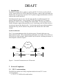
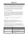
Fax Relay/Intercept
Product User Manual
MESi
10909 Lamplighter Lane
Potomac, Maryland 20854
E-mail: [email protected]
Web: www.mesi.net
DRAFT
Fax Relay/Intercept ............................................................................................................. 1
Product User Manual .......................................................................................................... 1
1
Introduction ................................................................................................................. 3
2
Protocol Compliance................................................................................................... 3
2.1
ITU V series modems ......................................................................................... 3
2.2
T.30 ..................................................................................................................... 4
2.3
T.38 ..................................................................................................................... 4
3
Major Software Modules ............................................................................................ 4
3.1
Modem Modules ................................................................................................. 4
3.2
Fax Protocol Modules ......................................................................................... 5
3.3
Network Modules................................................................................................ 5
3.4
Miscellaneous Modules ...................................................................................... 5
4
Data Structures ............................................................................................................ 6
5
Initialization ................................................................................................................ 6
5.1
Channel Initialization Method 1 ......................................................................... 7
5.1.1 Channel Memory ............................................................................................ 8
5.1.2 RlyInitChannelStruct ...................................................................................... 8
5.1.3 RlyRelayInitChannel....................................................................................... 9
5.1.4 SampleCode .................................................................................................... 9
5.1.5 Call Termination ........................................................................................... 10
5.2
Channel initialization Method 2........................................................................ 10
5.2.1 Statically declaring the memory ................................................................... 10
5.2.2 RlyRelayInit .................................................................................................. 10
5.2.3 Sample Code ................................................................................................. 11
5.3
Configurable Parameters ................................................................................... 12
5.3.1 Rx Frame Generation .................................................................................... 12
5.3.2 T.38 Corrigendum 1 ...................................................................................... 13
6
Call Maintenance ...................................................................................................... 13
6.1
Sending network data packets to the relay ........................................................ 13
6.2
Processing audio samples ................................................................................. 14
6.3
Getting Packets from the Relay ........................................................................ 15
6.4
Sample Code ..................................................................................................... 16
7
Intercept .................................................................................................................... 17
7.1
Required Entries................................................................................................ 17
7.2
Monitor Entries ................................................................................................. 17
7.3
V.21 Message Struct ......................................................................................... 18
7.4
Aborting an Intercept ........................................................................................ 18
7.5
InterceptFax ...................................................................................................... 19
7.6
Sample Code ..................................................................................................... 19
8 MESi Custom Telco Interface Box (Hookswitch) .................................................... 20
8.1 Manual Mode ................................................................................................ 20
8.2 Remote Mode ................................................................................................ 20
DRAFT
1
Introduction
The MESi Fax Relay allows vendors to quickly add ITU-T T.38 Fax over IP or ITU-T
I.366.2, Annex M Fax over ATM to their suite of products. Built on top of the MESi Fax
Modem suite, the upper layers provide T.30/T.4 protocol support and interfaces to the fax
modems and network interfaces.
Switching network types is easy, since the same interface is used between the T.30
protocol and the networks. Users requiring TCP/IP simply link in the TCP module.
Switching to ATM is as easy as linking in the ATM module. The fax relay software is
flexible enough to support other protocols as well. Interfacing to the Fax Relay involves
servicing two queues thru function calls. Two functions transfer network data packdts to
and from the relay, and one interface call generates and consumes the codec audio
samples.
System Architecture.
The T.38 recommendation provides for real-time group 3 facsimile deliveries over
Internet Protocols (IP). This recommendation permits the use of either TCP or UDP over
IP for delivery of the facsimile, which would be any IP network, including the Internet. A
block diagram is shown in Figure 1.
IP Network
Calling G3 Fax
Called G3 Fax
T.38 Emitting Gateway
T.30 fax
(PSTN)
T.38 Receiving Gateway
T.38 over IP
T.30 fax
(PSTN)
Figure 1 – Facsimile Transmission over IP Networks
2
2.1
Protocol Compliance
ITU V series modems
The MESi fax modems are all fully compliant with the relevant ITU V series
recommendations:
• ITU-T V.17 APSK trellis-coded modem
DRAFT
• ITU-T V.21, channel 2 FSK modem
• ITU-T V.27ter QPSK/8PSK modem
• ITU-T V.29 APSK modem
Please refer to the Vsim/Vmodem Product Manual for deviations.
2.2 T.30
The relay is fully compliant with the relevant sections of the ITU-T T.30
Recommendation. Support for binary file transfers, HKM and HFX secure faxes, RSA
secure faxes is not included.
2.3 T.38
The relay is fully compliant with the TCP and UDP implementation of the ITU-T T.38
Recommendation.
3
Major Software Modules
The software is divided into 3 sections; modem protocols, fax protocols, network
protocols and miscellaneous support.
3.1 Modem Modules
The fax modems are all contained in separate files. This allows for easy system
configuration when the user divides the support between a dsp and host processor or if all
modulation schemes are not supported.
Callprog.c contains code for call progress support. This is an optional module used
during the call establishment phase and in conjunction with hook switch support to place
and answer calls.
Common.c contains support for QAM modulation and demodulation.
Dtmf.c contains code for DTMF detection.
Fsk.c contains the FSK modulation and demodulation code used by the V.21 modulation.
Gendet.c contains the generic detectors that analyzes the spectral content of the incoming
signal, and optionally starts the appropriate modem based on the results of the analysis.
Filter.c contains Goetzel and bandpass filters used in the modems.
Rxtx.c contains the sequencer calls to the modem transmitter and receiver.
Tcm.c contains support for trellis coded modulation used in V17.
V17.c contains support for V.17 data pump.
V21.c contains the 300 bps V.21 data pump.
DRAFT
V27.c contains support for V.27ter data pump.
V29.c contains support for V.29 data pump.
3.2 Fax Protocol Modules
Bufmgr.c contains the buffer manipulation routines used by the relay. All
communications between modules is accomplished by passing buffers between modules
through predefined linked lists.
Modemif.c implements the interface between the T30 state machines and the fax
modems. Its function is to translate the buffer commands from the protocol to
instructions the modems can use.
Relay.c is heart of the relay. All user interface functions are implemented here.
Sequence.c contains the sequencer code that drives the state T30 state machines.
T30.c contains the T.30 protocol state machines.
T4.c contains T.4/T.6 encoding and decoding routines used for tif generation in intercept
mode.
T38.c contains the T.38 protocol routines that map the MESi native packets to T.38
packets.
3.3 Network Modules
NetIf.c contains the network dispatcher that allows for multiple transport protocol stacks.
3.4 Miscellaneous Modules
Bitrev.c contains general purpose bit reversing code required for the data interface with
the modems.
Fax2tif.c contains code to generate .tif files from the incoming fax pages. It is normally
not used in the fax relay mode, only in intercept mode.
G711.c contains code for the G711 Mu-law and A-law coders and decoders. The
intercept mode support both 8-bit encodings as well as 16-bit binary and ASCII.
DRAFT
4
Data Structures
All of the data structures are published in MESi header files. The user can examine any
structure member for performance monitoring.
BufStruct is defined in bufmgr.h and contains the memory buffers used by all of the fax
relay components (modems, protocol and network). The size and number of buffer
sections is determined at channel initialization. Typically, 200 buffer sections of 30
octets each is used for the relay. This is adequate for a 1 second delay for most fax
transmissions. If no delay is anticipated, e.g. the network has separate storage for packets
that the relay can not hold, the number of sections can be reduced to 100. If longer
delays are anticipated, the user can either 1) add additional buffer sections
(approximately 100 buffer sections are needed for each second of delay) or buffer the
packets externally until the relay can accept them.
ModemIfStruct is defined in Modemif.h and contains the memory structure for the
interface between the T30 protocol and the fax modems.
ProtocolStruct is defined in t30.h and contains the protocol specific variables used in the
relay.
RX_BLOCK is defined in rxtx.h and contains the variables for the modem
demodulators.
SeqStruct is defined in sequence.h and is the memory structure used by the protocol
sequencer to manipulate state machines, events and actions routine.
START_PTRS is defined in rxtx.h and contains pointers to the various modem blocks.
TX_BLOCK is defined in rxtx.h and contains the variables for the modem modulators.
5
Initialization
Before a fax channel can be used, the data structure must be initialized. Each channel
must contain the structures in the table below. There are two possible ways to initialize
the relay. 1) Provide the relay with a block of memory and allow the relay to fit the
internal components into the block. This is the easiest approach, but is not flexible. All
data may or may not be in on chip memory. This may impact mips if the modem blocks
are in memory with wait states. 2) The second approach allows the user to allocate the
structures. The pointers to the memory are then passed to the fax init routine.
Note: MIP and Memory numbers quoted and posted are for the optimum configuration.
Placing sections/structures in non-optimal locations may effect processor performance.
The following structures and buffers are required for each channel:
DRAFT
Name
Sequencer
Buffers
Type Size
Struct Sizeof(struct SeqStruct)
Struct sizeof (struct BufStruct)
See Note 1 below
Struct Sizeof(struct ModemIfStruct)
Modem
interface
Modem
Struct Sizeof (struct START_PTRS)
pointers
Modem
Short sizeof( struct TX_V27_block )
Transmitter
int
Modem
Short sizeof( struct RX_V27_BLOCK )
Receiver
int
Transmit
Short 161
Samples
int
Receive
Short 161
Samples
int
Transmit
Short
Data
int
35
Receive
Short
Data
int
31
Transmit
Short 2*6
internal
int
buffer
Receive
Short 2*63
internal
int
buffer
Equalizer
Short 2*64
Coeffs
int
Decoder
Short sizeof( struct TCM8_DECODER_BLOCK )
int
Trellis
Short TCM8_DELAY_STATES*TCM8_LOOKBACK_LEN
Decoder
int
Alignment
1
1
1
1
128
128
256
256
64
32
1
128
1
1
1
Note 1: The size of the buffer structure is dictated primarily by the number of sections
and the size of the buffer sections. The pound-define NSECTIONS is used in the
declaration of BufStruct. Set NSECTIONS in the options file (e.g. faxrelay.opt) to the
desired size.
Note 2: Alignment of memory sections is specific to some DSP devices used for
implementation.
5.1 Channel Initialization Method 1
The primary method is to allow the relay to initialize the structures.
DRAFT
5.1.1 Channel Memory
Each fax call must have its own channel memory. The channel memory contains all of
the modem and protocol states and data. There are two ways to declare channel memory;
statically or dynamically.
5.1.1.1 Static Channel Memory
Static declaration of the memory uses the pound-define RELAY_CHANNEL_SIZE to
calculate the channel size. RELAY_CHANNEL_SIZE in turn uses the pound-define
NSECTIONS to compute the channel buffer memory. NSECTIONS defaults to 200, but
can be overridden in the options file.
unsigned char FaxMem[RELAY_CHANNEL_SIZE];/* fax relay channel memory */
This would allocate a fax channel with the default 200 buffer sections.
5.1.1.2 Dynamic Channel Memory
The alternative is to dynamically allocate the channel memory. First estimate the size of
the channel memory.
int sizeChannel;
unsigned char *FaxMem;
sizeChannel=RlyGetChannelSize( 200 ); /* 200 buffer sections */
Then allocate the channel memory;
FaxMem=malloc(sizeChannel);
5.1.2 RlyInitChannelStruct
After the memory has been reserved, initialize the channel. The RelayInit structure
contains supplementary information needed to set up the call. Initialization data is passed
by structure in lieu of function parameters.
The RlyInitChannelStruct is declared in relay.h and current supports the following fields.
5.1.2.1 Layer3
Layer3 is a bit field that describes the transport protocol to be used. Multiple bits can be
selected if needed. Valid options are:
Tag
T30_T38
T30_NATIVE
T30_UDP
Function
T.38 packet format
MESi Native packet format
When protocols use different packet formats for Tcp and
Udp, this specifies Udp packet format.
T30_REDUNDANT_UDP When protocols use different packet formats for Tcp and
DRAFT
Udp, this specifies Udp packet format with redundancy.
When protocols use different packet formats for Tcp and
Udp, this specifies Tcp packet format.
T30_TCP
5.1.2.2 RelayFunction
RelayFunction is an enumeration that describes the function to be performed. Only one
mode may be selected at a time.
Enumeration
TFaxRelay
TFaxIntercept
TVoiceRelay
TDataRelay
Funtion
Relay a fax transmission
Intercept (decode) a fax transmission
Relay voice
Relay a data call
5.1.3 RlyRelayInitChannel
struct FaxStruct RlyRelayInitChannel(unsigned char *FaxMem,
int sizeChannel,
struct RelayInitStruct *relayinit);
where
FaxMem is the address of the channel memory block allocated above,
sizeChannel is the size of the the FaxMem array,
relayinit is the address of the RlyInitChannelStruct
The functions return the handle to the channel which is needed for subsequent call
maintenance call.
5.1.4 SampleCode
This code snippet sets up a channel dynamically and initializes the channel. The pointer
to the channel structure is saved in the variable ‘Faxs’.
struct RlyInitChannelStruct RelayInit;
int sizeChannel;
unsigned char *FaxMem;
struct FaxStruct *Faxs;
sizeChannel=RlyGetChannelSize( 200 );
FaxMem=malloc(sizeChannel);
RelayInit.Layer3 = T30_T38 | T30_UDP;
RelayInit.RelayFunction = TfaxRelay;
Faxs=RlyRelayInitChannel(FaxMem,sizeChannel,&RelayInit);
At this point, the relay is ready to accept packets and process samples.
DRAFT
5.1.5 Call Termination
If the memory was malloc’d, the address of the start of the block is saved in the FaxStruct
so that it can be used in the free call later. For some implementation ( TI C54x ), the
placement of FaxStruct may not be at the start of the block.
free(Faxs->MemStart);
5.2 Channel initialization Method 2
This method involves statically declaring the relay channel memory, aligning the sections
as appropriate and then calling RlyRelayInit.
5.2.1 Statically declaring the memory
This method allows the user the most flexibility if placing structure in memory. It
requires the most work on the user’s part.
Warning!! Failure to correctly align the structure will result in the relay failing or the
DSP to crash.
5.2.2 RlyRelayInit
To use this method, declare the memory elements and then call the RlyRelayInit. If
alignment is required, this must be done in the linker command files.
int RlyRelayInit(struct FaxStruct *Faxs,
struct START_PTRS *start_ptrs,
int *TxBlock,
int *TxSample,
int *TxData,
int *TxFir,
int *RxBlock,
int *RxSample,
int *RxData,
int *RxFir,
int *EQCoef,
int *ECCoef,
int *Decoder,
int *TraceBack,
struct ModemIfStruct *Mif,
struct SeqStruct *Seq,
struct ProtocolStruct *Proto,
int Layer3,
int RelayFunction);
where
start_ptrs is the address of the modem struct START_PTRS
TxBlock is the address of an array of ints of size of struct TX_V27_BLOCK
DRAFT
TxSample is the address of an array of ints of size TX_SAMPLE_LEN
TxData is the address of an array of ints of size TX_DATA_LEN
TxFir is the address of an array of ints of size TX_FIR_LEN
RxBlock is the address of an array of ints of size struct RX_V27_BLOCK
RxSample is the address of an array of ints of size RX_SAMPLE_LEN
RxData is the address of an array of ints of size RX_DATA_LEN
RxFir is the address of an array of ints of size RX_FIR_LEN
EQCoef is the address of an array of 128 ints
ECCoef is not needed for the fax relay
Decoder is the address of an array of ints of size struct TCM8_DECODER_BLOCK
TraceBack is the address of an array 120 ints
Mif is the address of the ModemIf struct
Seq is the address of the SeqStruct *Seq,
Proto is the address of the ProtocolStruct
Layer3 is the protocol (see section xxx)
RelayFunction is TFaxRelay
The function return 0.
5.2.3 Sample Code
The following code snippet declares all of the fax structures for one channel and then
initializes the channel. The variable ‘Faxs’ contains the relevant channel info. Calls to
channel maintenance require the address of the Faxs variable.
int TxBlock[ sizeof(struct V27_TX_BLOCK)/sizeof(int) ];
int TxSample[ TX_SAMPLE_LEN ];
int TxData[ TX_DATA_LEN ];
int TxFir[ TX_FIR_LEN ];
int RxBlock[ sizeof( struct V27_RX_BLOCK)/sizeof(int) ];
int RxSample[ RX_SAMPLE_LEN ];
int RxData[ RX_DATA_LEN ];
int RxFir[ 128 ];
int EQCoef[ 128 ];
int TraceBack[ 120 ];
int Decoder[ sizeof( struct TCM8_DECODER_BLOCK)/sizeof(int) ];
struct ModemIfStruct Mif;
struct SeqStruct Seq;
struct BufStruct Buf;
struct ProtocolStruct Proto;
struct FaxStruct Faxs;
struct START_PTRS start_ptrs;
RlyRelayInit(&Faxs,
&start_ptrs,
TxBlock,
TxSample,
TxData,
TxFir,
RxBlock,
DRAFT
RxSample,
RxData,
RxFir,
EQCoef,
NULL,
Decoder,
TraceBack,
&Mif,
&Seq,
&Buf,
&Proto,
T30_T38 | T30_UDP,
TFaxRelay
)
It is extremely important that sections which require alignment on powers of 2 be aligned
in linker command/control files. Failure to do so will result in failure of the relay.
5.3 Configurable Parameters
After the channel has been initialized, some of the default modem internal parameters can
be changed.
5.3.1 Rx Frame Generation
When the relay is receiving training data and fax pages, it collects symbols and packs the
symbols into octets. When the threshold has been reached, a network packet is
generated. The size is based on a time interval, not an absolute data size. The default
value is 10 ms. The packet size is computed as:
( ceiling( rate * rxFrameTime / 1000) + 7 ) >> 3
To change the rxFrameTime from its default value (10), execute the following line after
the init call (section 5.1.3).
f->ModemIf->rxFrameTime= 15;
/* change frame generation to 15 ms */
where f is tee handle returned from init call (see 5.1.3).
The effect of a non-integer number of octets being generated by this algorithm will mean
that at most one packet will be produced every rxFrameTime milliseconds. There may be
time slices that do not produce any outbound packet.
For example, a 2400 bps fax with a rxFrameTime of 15 ms, will generate a packet when
there are 5 octets available, but the octets are produced at a rate of 4.5 octets per 15 ms.
The net effect is that every 10 rxFrameTimes, 45 (4.5 * 10) octets will be generated, but
only 9 of those rxFrameTimes will produce an outgoing packet ( 9*5 = 45 octets)
DRAFT
5.3.2 T.38 Corrigendum 1
The original T.38 omitted an ellipsis in the definition of Data-Field. The effect of this
omission changes the encoding of the field. The default of the relay is the post
corrigendum. To force the relay to encode and decode T.38 packets by the original T.38
standard, it is necessary to execute a macro after the relay has been initialized. There is
no way for T.38 to distinguish internally between the two coding methods. It is
incumbent on the user to determine during call setup which method is used.
To get the original T.38 behavior, call
T38PreCorrigendum(f);
where f is the handle returned from init call (see 5.1.3).
6
Call Maintenance
After the channel has been initialized, the user needs to periodically call the interface to
keep an uninterrupted flow of audio samples for the transmitter. Failure to keep the
transmitter from under-running will result in the failure of the fax call.
NOTE: The three call maintenance functions are not thread safe. If the application has
separate processes for data packet processing and audio processing, the user needs to
ensure each function call returns before calling another function. All three functions use
a pool of internal buffers to manipulate data which are maintained in a linked list. If the
audio processing function ‘RlyRelayIf()’ is interrupted by an incoming packet
‘RlyPacketToRelay()’, there is a good chance the link list will get corrupted.
6.1 Sending network data packets to the relay
To place packets from the network in the relay for regeneration, the user needs to call
int RlyPacketToRelay(struct FaxStruct *f, /*pointer to fax structure */
unsigned char *msgbuf, /* pointer to packet */
int length )
/* length of packet */
where:
f is the fax handle returned from the RlyRelayInitChannel call
msgbuf is the address of a char array containing the packet for the relay
length is the length of the packet
This function returns:
Return
Value
1
0
-1
Meaning
Packet was accepted by the relay
The internal memory is temporarily full. Send the packet again at a later time.
Call Failed. The amount of memory allocated during channel initialization was
DRAFT
too small and the packet will never be accepted by the relay.
You can send any or all packets pending to the relay, one at a time, but must monitor the
return value to see if the packet was accepted by the relay. If the return value is –1, then
the call has failed. This will happen only if the number of buffer sections or the size of
the buffer sections was made too small during the init call. This indicates the packet is
too large for the relay to handle. If the return value was 0, then the internal buffers are
temporarily filled and the user should attempt to send the packet to the relay at a later
time, e.g. after RlyRelayIf has been called. This indicates temporary congestion.
6.2 Processing audio samples
RlyRelayIf must be called periodically to process the samples. It is incumbent on the
user to ensure that there are always samples available at the codec output and that the
codec inputs do not overflow. RlyRelayIf processes ‘length’ 16-bit incoming samples
pointed to by ‘In’ and generates ‘length’ 16-bit samples and places them in the array
‘Out’. The relay uses network packets delivered with the RlyPacketToRelay call as
stimulus and generates and queues packets for the network which are later retrieved by
calling RlyPacketFmRelay.
int RlyRelayIf(struct FaxStruct *f, /* pointer to fax structure */
INT16 *In, /* pointer to samples from the pstn (relay read) */
INT16 *Out, /* pointer to samples to the pstn (relay writes) */
int length) /* number of samples to read and write */
where:
f is the fax handle returned from the RlyRelayInitChannel call
In is the pointer to an array of 16 bit ints that contains input audio for the relay
Out is the pointer to an array of 16 bit ints that contains output audio from the relay
length is the number of sample of audio to process
The RlyRelayIf function returns a value that is a bit field of error conditions. Any nonzero value should be considered fatal. At times, a fax can go through even when the
relay runs out of buffers. Forward error correction and redundant packets will save some
faxes, but a non-zero return code is an indication of an error and should not be considered
normal operation. The possible errors are:
Return Value
SEQ_HEALTHY
SEQ_BUF_POOL_EMPTY(0x01)
SEQ_BUF_RERETURN(0x02)
SEQ_BUF_INTERNAL(0x04)
Meaning
The relay if functioning normally
The relay has run out of buffers.
The internal memory pool has been corrupted and a
section of memory that was not marked in use has
been returned to the memory pool.
The internal memory pool has been corrupted. The
size of the buffer and the number of buffer sections
used do not agree.
DRAFT
SEQ_SM_FULL(0x08)
The number of state machine tables is too small to
hold an additional state machine. Rebuild with a
larger state machine array.
SEQ_EVENT_OVERFLOW(0x10) The event buffer is too small to hold any additional
events. Rebuild with a larger event buffer.
SEQ_TIMER_OVERFLOW(0x20) The timer stack is too small to hold any additional
timers. Rebuild with a larger timer stack.
6.3 Getting Packets from the Relay
After RlyRelayIf is called, network packets may be available. To get packets from the
relay, call:
int RlyPacketFmRelay(struct FaxStruct *f, /*pointer to fax structure */
unsigned char *msgbuf, /* pointer where packet will be placed */
int length )
/* max length of packet */
where
f is the fax handle returned from the RlyRelayInitChannel call
msgbuf is the address of a char array where the packet will be placed
length is the maximum size of the packet to be copied
The function returns:
Return Value
>0
0
<0
Meaning
Packet of length ‘Return Value’ was placed in msgbuf
No packet is available
The packet from the relay is larger than the size allocated by the length
parameter passed to the function. The ‘Return Value’ is the negative of
the size of the packet. The packet is held by the relay. Call
RlyPacketFmRelay() with a larger buffer to receive the packet.
The user should take all packets from the relay after RlyRelayIf is called. This frees up
internal buffer space. Failure to take all of the packets from the relay may cause
temporary congestion in trying to send packets to the relay (RlyPacketToRelay), or cause
outbound packets to be discarded.
DRAFT
6.4 Sample Code
This sample code is for a 10 ms call. Eighty samples of codec data are collected and then
the relay functions are exercised. This is repeated every 10 ms.
/* the user collects packets that need to be given to
* the relay and tries to deliver them all. Monitor the return
* value to see if the relay accepts the packet.
*/
while( packets_to_relay > 0)
{
/* copy the packet to the variable ‘packet’ and set
* the length of the packet to ‘len’ and then call
* RlyPacketToRelay
*/
{User code to move packets}
j=RlyPacketToRelay(Faxs,packet,len);
if ( j == 1 )
{
/* the relay accepted the packet. It can be
* be removed from the user’s queue.
*/
--packets_to_relay;
}
else if (j == -1)
{
{ User fatal error code processing }
}
else
{
/* The relay is temporarily full and will not
* accept the packet. The user holds onto this
* packet until the next 10ms cycle
*/
break;
}
}
/* collect 80 audio codec samples and put them in the array
* AudioIn. Then call the interface.
*/
{ User code to transfer audio samples from codec to AudioIn }
health=RlyRelayIf(AudioIn, AudioOut, 80, Faxs);
/* monitor the health for a non-zero value. Copy the AudioOut
* samples to the transmitter.
*/
{ User code to transfer audio samples from AudioOut to codec
and examine health value returned from relay}
DRAFT
/* Call RlyPacketFmRelay to get the length of the packet.
* Send the packet off to the network. Continue until all of
* the packets have been taken from the relay(return value==0).
*/
while ( ( len =
RlyPacketFmRelay(Faxs,packet, sizeof(packet))
>0)
{
{ User code to send packets to network }
}
7
Intercept
The fax intercept is designed to decode captured audio files and convert them to tagged
image format (tif) files. The intercept mode uses the same modems and drivers
internally, but uses a different state machine that acts more like a terminating fax than a
relay.
Using the intercept mode requires populating a few members of the Intercept structure
and calling the intercept. An intercept structure is defined to be a superset of all of the
modem and T.30 structures thus eliminating the need for multiple user declarations.
7.1 Required Entries
The following structure members must be populated before calling the intercept.
InterceptStruct
member
InWavFileName
OutTifFileName
BufLogFileName
TempFileName
modeBits
SummaryFileName
Contents
path to the input sample file
path to output tif file name
path to buflog if BUFLOG capabilities are enabled or NULL
path to temporary file name to be used in processing files
describe the audio recording format
MULAW
mu-law encoded 8 bit binary data
ALAW
a-law encoded 8 bit binary data
ASCII
ASCII text
BIG_ENDIAN
big endian 16 bit binary data
LITTLE_ENDIAN
little endian 16 bit binary data
path to the summary file (if desired) or NULL
7.2 Monitor Entries
During the execution of the intercept and after completion, the following intercept
structure members may be examined if desired.
InterceptStruct
Contents
DRAFT
Member
Dis
Csi
Nsf
Dtc
Cig
Nsc
Dcs
Tsi
Nss
PercentComplete
nPagesProcessed
T.30 DIS message (see V21MsgStruct)
T.30 CSI message (see V21MsgStruct)
T.30 NSF message (see V21MsgStruct)
T.30 DTC message (see V21MsgStruct)
T.30 CIG message (see V21MsgStruct)
T.30 NSC message (see V21MsgStruct)
T.30 DCS message (see V21MsgStruct)
T.30 TSI message (see V21MsgStruct)
T.30 NSS message (see V21MsgStruct)
integer value from 0 to 100 showing the percentage of audio
samples processed
number of fax pages generated
7.3 V.21 Message Struct
After the intercept has finished running, a tiff file is generated. The user may look at the
V.21 messages that have been populated in the structures. Each V21 message is a pointer
to a V21MsgStruct.
struct V21MsgStruct
{
int len;
unsigned char data[128];
};
7.4 Aborting an Intercept
To abort the decoding of a partially processed fax, set the ABORT_FLAG in the
modeBits member of the intercept structure. All completed pages are available in the
output tif file and all elements in the intercept structure are current and relevant up to the
point the ABORT_FLAG was detected.
This is only useful in a multi-process or multi-threaded application where a monitor
processes can abort a decoding process. The actual call to the intercept does not return
until the sample file is completely processed, but the intercept does monitor the modeBits
while decoding the sample file.
Intercept.modeBits
|=
ABORT_FLAG ;
DRAFT
7.5 InterceptFax
int InterceptFax(struct InterceptStruct *Intercept);
where:
Intercept is the address of the InterceptSturct
When completed, the function returns 0 on success.
In addition to the return codes listed for RlyRelayIf, these additional error values may be
returned.
Return Value
INTERCEPT_INVALID_INPUT_FILE
Meaning
The input filename specified could not be
opened.
INTERCEPT_INVALID_TIF_FILE
The output tif filename could not be
opened.
INTERCEPT_INVALID_BUFLOG_FILE
The buflog could not be opened.
INTERCEPT_INVALID_SUMMARY_FILE The summary file could not be opened.
INTERCEPT_INVALID_TEMP_FILE
The tempfile could not be opened.
INTERCEPT_NO_FAX_TONE
There was no CED, or V21 message in
the first 30 seconds of decoded sample
data.
INTERCEPT_MALLOC
The intercept could not allocate the
memory it needed to decode the fax.
7.6 Sample Code
Struct InterceptStruct Intercept;
int j;
Intercept.InWavFileName="c:\\demo\\FaxLab3pg.wav";
Intercept.OutTifFileName="c:\\demo\\FaxLab3pg.tif";
Intercept.BuflogFileName= NULL;
Intercept.SummaryFileName= “c:\\demo\\FaxSummary.txt”;
Intercept.Protocol.TempFileName="c:\\demo\\temp.tif";
Intercept.modeBits=MU_LAW;
InterceptFax(&Intercept);
/*
* optional code that demonstrates the format of the V.21 structures,
* and outputs the number of pages that were decoded
*/
for(j=0;j<Intercept.Tsi.len;++j)
printf(“%c”,Intercept.Tsi.data[j]);
printf(“Number of pages=%d\n”,Intercept.nPagesProcessed);
DRAFT
8
MESi Custom Telco Interface Box (Hookswitch)
The hookswitch provides telephone RJ-11 to stereo audio conversion. The unit can
be operated in either manual or remote modes. It is important to remember that the
interface unit does not provide loop current. This means that a fax machine, modem,
or handset cannot be connected directly to it; the unit must be connected thru a
Viking Box, Teltone Box, or PSTN.
8.1
Manual Mode
In manual mode, when the switch on the front panel is down, both channels are onhook and the connection from the telephone to the stereo jacks is broken. When the
switch is in the up position, both channels are taken off hook and the connection
from the telephone to the stero jack is made.
Note: Connection of the hookswitch to a PC is optional in this mode. The
hookswitch can provide ring indication if desired, but the hookswitch control is
provided by the front panel switch.
8.2
Remote Mode
The alternate method of interfacing with the hookswitch is thru a RS-232 connection.
The unit provides ring indication independently for each channel and control to place
either channel on hook or off hook.
The PC version of the MESi fax relay interfaces directly to the hookswitch unit.
There is no need for user intervention. When using the hookswitch without the PC
relay, the hookswitch communication with an external communications program.
Connect the hookswitch with any terminal program (Procomm, Hyperterminal, etc)
with the following settings:
Data Rate
Data Bits
Parity
Stop Bits
Flow Control
1200 bps
8
None
2
No hardware flow control
No software flow control
The hookswitch provides a simple command set for control. Note that these
commands are case sensitive.
Command
R
E
Description
Reset the hookswitch
Take right side off hook
DRAFT
F
G
H
Place right side on hook
Take left side off hook
Place left side on hook
The hookswitch also provides the following ring indications.
Response
A
B
C
D
Description
Ring detect right side
Ring undetect right side
Ring detect left side
Ring undetect left side