1
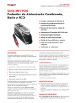
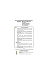
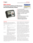
M
MFT1500 Series
Multifunction Tester
USER MANUAL
G
SAFETY WARNINGS
■
Safety Warnings
and Precautions
must be read and understood before the instrument is used. They must be observed during use.
■
The circuit under test must be switched off, de-energised and isolated befor e test connections are made when carrying out insulation and continuity
tests.
■
Continuity of protective conductors and earthed equipotential bonding of new or modified installations must be verified before carrying out an earth
fault loop impedance test, or RCD test.
■
Circuit connections and exposed metalwork of an installation or equipment under test must not be touched.
■
The live circuit warning and Automatic discharge are additional safety features and should not be regarded as a substitute for normal safe working
practices.
■
Do not change the rotary switch positions while a test is in progress.
■
The LCD ‘neon’ voltage indicators cannot reveal a Neutral - Earth reversal. They cannot be relied upon to identify circuit correctness and are for
guidance only.
■
After insulation tests, capacitive circuits must be allowed to discharge befor e disconnecting test leads.
■
The instrument should not be used if any part of it is damaged.
■
Test leads, probes and crocodile clips must be in good order, clean and with no broken or cracked insulation.
■
Ensure that hands remain behind guards of probes/clips when testing.
■
UK Safety Authorities recommend the use of fused test leads when measuring voltage on high energy systems.
■
Replacement fuses must be of the correct type and rating.
Failure to fit the correctly rated fuse will result in damage to the instrument in the event of an overload.
■
The battery cover must be in place whilst conducting tests.
NOTE
THE INSTRUMENT MUST ONLY BE USED BY SUITABLY TRAINED AND COMPETENT PERSONS.
Users of this equipment and/or their employers are reminded that Health and Safety Legislation requires them to carry out valid risk assessments of all
electrical work so as to identify potential sources of electrical danger and risk of electrical injury such as inadvertent short circuits. Where the
assessments show that the risk is significant then the use of fused test leads constructed in accordance with the HSE guidance note
GS38 'Electrical Test Equipment for use by Electricians' should be used.
2
CONTENTS
Safety Warnings
Description
Overview of MFT1500 Series
Instrument Layout
Display
Control Panel
Front switch panel
Connection panel
Test Leads
Battery /fuse warning, fitting and replacement
Operation
General operation
Live circuit warning
Test button lock
Backlight (MFT1502 only)
Auto shut-off
Polarity indication
Illuminated Switched Probe
Operation
Voltage measurement (V)
Continuity
Continuity measurement
Lead Null
Continuity Buzzer
Buzzer threshold
Insulation
Insulation resistance
Insulation Voltage ranges
Test lock
Loop impedance
NO TRIP (15mA) loop test
High Current Loop test
2
4
4
4
4
4
4
4
4
5
6
6
6
6
6
6
6
6
6
7
7
7
8
8
8
8
8
8
9
9
P-N and P_P loop test
PSC
Residual Current Device (RCD testing)
1/2I, I, 5 x I, 0 & 180°
14
Ramp testing
DC Sensitive RCDs
15
Technical specification
16
Accessories
19
Repair and Warranty
20
Symbols used on the instrument are:
F
G
t
G
Caution: risk of electric shock
Caution: refer to accompanying notes
Equipment protected throughout by Double
Insulation (Class II)
c
Equipment complies with current EU directives.
>500V
Maximum nominal system voltage of 500 V
Max 300 V
CAT III
g
Maximum 300 V a.c. CAT III to Earth
3
DESCRIPTION
Thank you for purchasing the MFT1500 Multifunction Tester. The
MFT1500 series of tester is compact and designed to perform all of the
functions required by the electrical contractor to fully test domestic,
commercial and industrial wiring. Specially designed to comply with UK,
European and other International wiring regulations and standards, the
MFT1501 and MFT1502 may be used on all single and three phase
systems with rated voltages up to 300 Volts a.c. rms to earth/ground.
All test leads supplied with the MFT1501 and MFT1502 form part of
the measuring circuit of the instrument and must not be modified or
changed in any way, or be used with any other electrical instrument
or appliance.
Test selection
Display
Battery cover (side panel)
Connection
indicators
Contact
A plug severed from the power cord MUST be destroyed, as a plug
with bare conductors is hazardous in a live socket outlet.
Ohms
Null
OVERVIEW OF MFT1500 SERIES
RCD range
selection
Noise warning
Fuse warning
Battery status
Temperature
warning
ORANGE (BUZZER THRESHOLD)
BLUE (0º - 180º)
YELLOW (TEST BUTTON)
BLACK (BACKLIGHT)
Warning
RED (TEST LOCK)
Continuity and
insulation
connections
Switched probe
4
LOOP & RCD
connections
Mains plug test
lead
REPLACING FUSES AND BATTERIES
Battery and Fuse fitting/Replacement
Battery type: 8 x 1.5 V Alkaline LR6 (AA)
Fuse type: 500 mA (F) HBC 10 kA 500 V
Low battery warning symbol
Fuse blown symbol
To replace the fuse
Should the main fuse fail, the symbol
will be displayed.
Disconnect the instrument from any circuits.
Remove the battery cover as above.
To test battery condition
With the MFT1500 switched to the OFF position, press the RED
test
lock and the YELLOW TEST button together. The battery voltage is
displayed. If the battery symbol
also appears the batteries need
replacing.
L
The blown fuse should be replaced with a 500 mA (F) HBC
10 kA 500 V fuse (Megger part no.25950-039)
Replace the battery cover.
To replace batteries
Switch off the instrument and disconnect (the instrument) from any
electrical circuits.
Remove the battery cover.
Slide out the battery clip and remove the dead cells.
Refit new batteries following correct polarity as marked on the battery
holder.
Replace the battery holder and cover.
Note: - Incorrect battery cell polarity can cause electrolyte leakage,
resulting in damage to the instrument.
5
OPERATION
GENERAL OPERATION
Note: These functions are generally apply and not limited to an
individual test function.
Polarity Indication
If connected to a single-phase power supply by a plug or by the 3-wire
lead set, three LCD ‘neons‘ marked L-PE, N-PE and L-N respectively will
indicate supply polarity.
Live circuit warning - Test Inhibit
Testing is automatically inhibited if:
During insulation testing - an external voltage >55 V is
present on the terminals
L-PE
N-PE
L-N
During continuity testing - a voltage >10 V is present on the
terminals
Correct supply indication
During RCD or No-Trip loop testing - a voltage >270 V is
present
Live –Neutral swapped
During Loop testing - a voltage >480 V is present
Test button lock
To lock the test button hold down the RED
holding down the YELLOW TEST button.
L test lock button whilst
Intelligent Backlight (MFT1502 only)
Both the display and range knobs have a backlight. To activate, press
the BLACK
button.
J
To disable the Intelligent backlight function, press the BLACK
button and the RED
lock button together.
L
J
Repeat to enable the intelligent backlight.
Instrument Auto shut-of f
Automatically activated after 5 minutes of instrument inactivity.
To restore operation press the RED lock button or switch the instrument
off and on.
6
If a voltage is detected between their respective two wires, the ‘neon’(s)
will activate.
Any other combinations should be investigated further. However the
LCD 'NEONS' cannot be relied upon to identify circuit correctness and
are for guidance only.
Note: - The presence of a voltage between phase and earth does not
prove earth continuity, as the earth could have a high resistance and a
voltage would still be measured. To test earth continuity refer to the
sections on loop resistance or RCD testing.
Warning: The LCD 'Neons' are invalid when using the two wire lead-set
and should be ignored.
ILLUMINATED SWITCHED PROBE SPL1000 (MFT1502 ONLY)
The Illuminated switched probe accessory replaces the RED 4 mm test
lead. It can be used anywhere that the 4 mm lead set is specified in this
user guide.
Operation
The YELLOW button duplicates the function of the TEST key on the
instrument, allowing quick and easy testing.
The BLACK switch operates a white LED, which illuminates the probe tip
for use when testing under low light levels.
There is also a visual indication via a red/green LED to notify the user of
the display status, the meanings are as follows:
OR Using the Mains plug Lead set (OPTION3)
Voltage between the L and E pins is displayed
Note: - When connected to the circuit under test the instrument will
automatically display AC or DC voltage measurement up to 500 V.
Green :
A valid result is present on the display or the
continuity buzzer is buzzing.
This function will continue to work if the fuse is blown.
Red:
A warning is being shown on the display, testing
will be inhibited.
CONTINUITY
Warning: Prior to any continuity testing, ensure the circuits under test
are isolated and not live
VOLTAGE MEASUREMENT [V]
TEST LEAD CONNECTION
Z
TEST LEAD CONNECTION
OPTION 1
OPTION 2
OPTION 3
OPTION 1
OPTION 2
2 wire lead
Switched
Mains plug
2 wire lead
Switched
set
probe
test lead L-E
set
probe
BLACK
BLACK
BLACK
BLACK
RED
RED
PROBE
PLUG
Set the Rotary range knob to the [V] range
(The position of the right hand ‘mA’ rotary range knob does not matter)
Two wire lead set or Switched Probe connection
Using the 2-wire lead set OPTION 1 or OPTION 2
1. Connect the test leads as shown.
2. DC Voltage (V) or AC Voltage (V~) is automatically displayed.
PROBE
Set the left hand rotary range knob to the Ω range required.
(The position of the right hand rotary range knob does not matter).
Continuity measurement can be made using one of the 2 options shown
above.
A continuity measurement is made automatically when the test leads are
connected to the circuit under test. The contact
symbol on the
display closes when a resistance of approximately 200 kΩ or less is
detected.
7
Lead Null (up to 9.99
)
Short test probes or clips together and press the YELLOW TEST button
on the instrument (or on the switched probe if fitted). The
will
be displayed to indicate lead null is active.
z
This null value is stored until the YELLOW TEST button is pressed
again.
To cancel the LEAD NULL, press the YELLOW TEST button.
Continuity Buzzer
Z
Test leads OPTIONS 1 or 2 above
200 mA when measuring 2 Ω.
Possible sources of error
Measurement results can be affected by the following:
■
The impedance of operating circuits connected in parallel.
■
Impedance such as inductors that vary during the measurement.
■
A poor connection to the circuit under test, which can give readings as
much as 100 mΩ (0,10 Ω) high. The best way to avoid this error is to
use sharp prods and press these firmly into the conductors being
measured.
The MFT1500 buzzer will sound continuously if the resistance between
the leads is less than a set limit (Default value 2 Ω).
INSULATION RESISTANCE [MΩ] [250 V] [500 V] [1000 V]
Warning: Prior to any insulation testing, ensure the circuits under test
are isolated and not live.
If being used with the illuminated switched probe (OPTION 2)
continuity is also indicated by a GREEN LED on the probe.
TEST LEAD
CONNECTION
To turn off the buzzer press the TEST button whilst in BUZZER mode.
The display will indicate ON or OFF status.
Buzzer threshold
The resistance at which the buzzer stops sounding can be changed to
meet individual test requirements. Press the ORANGE
button to
select the resistance limit.
Z
Selectable limits of 2 Ω, 5 Ω, 10 Ω, 20 Ω, 50 Ω and 100 Ω.
OPTION 1
OPTION 2
2 wire lead
Switched
set
probe
BLACK
BLACK
RED
PROBE
Set the left hand rotary range knob to the required INSULATION Range.
This setting is stored even when the instrument is switched off.
250 V Insulation measurement to 99.9 MΩ
Notes:Method of measurement
The 2-wire lead set must be used for this measurement. The instrument
produces a d.c. voltage of nominally 4,5 V with a current limit of at least
500 V Insulation measurement to 299 MΩ
8
1000 V Insulation measurement to 499 MΩ
(The position of the right hand rotary range knob does not matter.)
with a circuit capacitance up to 5 µF.
To initiate insulation testing press and hold the YELLOW TEST button on
the instrument or the switched probe if connected.
LOOP IMPEDANCE [LOOP] TESTING
Loop impedance measurement can be made via installation sockets using
the plug terminated test lead, OPTION 3, or at any other convenient point
on the installation using a two/three wire lead set, OPTION 1 OR 2.
Release the test button after the displayed reading has settled.
TEST LOCK
To lock down the test button press the YELLOW TEST button followed
by the RED LOCK
button.
L
A warning triangle G will appear in the display while the test lock is
active.
Press the YELLOW TEST button to stop the test.
Note: - A 1000 V warning is displayed whenever the 1000 V range is
selected and the test button pressed
The MFT1501 and MFT1502 will measure the loop resistance from the
supply end of the standard test leads, allowing for their resistance.
NON TRIPPING LOOP TESTS [NO TRIP]
Set the LEFT rotary range knob to the required LOOP range as
described below:
OPTION 3
OPTION 1
OPTION 2
3 wire
Switched
Mains plug
measurement
Probe
test lead
Warning: The test voltage will be permanently present on the test
probes or crocodile clips when in the locked modes.
BLACK
BLACK
GREEN
GREEN
Notes: - Auto discharge - Auto discharge facility automatically and safely
discharges connected circuit after test via 250 kΩ resistor.
RED
Live circuit warning - operates when connected to Live circuits > 25 V.
Test Inhibited - an audible alarm operates at >55 V. The instrument
will not perform a test until the voltage source has been removed.
Method of measurement
A current limited (2 mA) d.c source is used, and the resistance is
calculated from measurements of the voltage and current.
PROBE
PLUG
(The position of the right hand rotary range knob does not matter.)
[NO TRIP] LOOP-TESTING - SINGLE PHASE TESTING ONLY
The NO TRIP loop test is a high resolution low current earth loop
resistance measurement (Loop L-PE 0.01 Ω) range which does not trip
RCDs with a rated current 30 mA or higher.
The voltage is only present when the test button is pressed or the test
lock is active. A measurement of the terminal voltage is made before the
test and if this exceeds 55 V the test is disabled. The reading is stable
9
[NO TRIP] PHASE TO EARTH LOOP IMPEDANCE MEASUREMENT
(AT A POWER SOCKET)
Test Lead set: OPTION 3
OPTION 2
2 wire lead
Switched
Mains plug
set
probe
test lead
1.
Select NO TRIP Loop test range.
2.
Insert the plug into an installation socket.
GREEN
3.
Supply voltage and polarity are displayed.
RED
4.
The test will ‘beep’ and automatically start when voltage is
detected.
5.
Measured loop value is displayed
If desired the test can be repeated by pressing the YELLOW TEST button.
[NO TRIP] EARTH LOOP IMPEDANCE MEASUREMENT (NOT AT A
POWER SOCKET)
Test Lead set: OPTION 1 or OPTION 2
1.
Firmly connect the GREEN lead to EARTH, the BLACK lead
to NEUTRAL and the RED lead to PHASE.
2.
Perform the loop test, as above for power socket.
If desired the test can be repeated by pressing the YELLOW
TEST button.
HIGH CURRENT LOOP-TESTING [25 A]
Single Phase and Phase to Phase loop testing on circuits that are NOT
protected by RCD
GREEN
PLUG
PROBE
Set the instrument to the [25 A] Loop test range
25 A Phase to Earth loop impedance measurement (at a power
socket):
Test Lead set: OPTION 3
1.
Insert the plug into an installation socket.
2.
Supply voltage and polarity are displayed.
3.
The test will ‘beep’ and automatically start when voltage is
detected.
4.
Measured loop value is displayed.
If desired the test can be repeated by pressing the YELLOW
TEST button.
25 A Phase-Earth loop impedance (not at a power socket):
Test Lead set: OPTION 1 or 2
1.
2.
10
OPTION 3
OPTION 1
Connect the GREEN lead to EARTH and the RED lead to PHASE
Supply voltage is displayed.
Warning: The LCD 'Neons' are invalid when using the two wire lead-set
and should be ignored.
3.
The test will automatically start when voltage is detected.
4.
Measured loop value is displayed.
If desired the test can be repeated by pressing the YELLOW
TEST button.
BONDED METALWORK TESTING
Test Lead set: OPTION 1 or 2
1.
Connect the GREEN lead to the bonded metalwork.
2.
Connect the RED lead to PHASE.
3.
Supply voltage is displayed.
PHASE-NEUTRAL OR PHASE-PHASE LOOP IMPEDANCE
Test Lead set: OPTION 1 or 2
1.
Connect the GREEN lead to NEUTRAL and the RED lead to
PHASE (or the 2nd PHASE for Phase to Phase loop
measurement).
2.
The supply voltage is displayed.
Warning: The LCD 'Neons' are invalid when using the two wire lead-set
and should be ignored.
3.
The test will automatically start when voltage is detected.
4.
Measured loop resistance is displayed.
If desired the test can be repeated by pressing the YELLOW
TEST button.
Warning: The LCD 'Neons' ar e invalid when using the two wire lead-set
and should be ignored.
4.
The test will automatically start when voltage is detected.
5.
Measured loop value is displayed.
If desired the test can be repeated by pressing the YELLOW
TEST button.
11
PROSPECTIVE SHORT CIRCUIT CURRENT [PSC]
OPTION 1
OPTION 2
2 wire measurement
Switched
PHASE TO NEUTRAL PSC
As for the 25 A Phase to Earth PSC test but with the following test lead
connections:
probe
1.
Connect the GREEN lead to the NEUTRAL and the RED lead to
PHASE.
2.
The test will ‘beep’ and automatically start when voltage is
detected.
3.
Measured PSC value is displayed.
GREEN
GREEN
RED
PROBE
Set the instrument to the [PSC] range
PSC is a 25 A two wire test.
PHASE TO EARTH PSC
Test Lead set: OPTION 1,2
1.
For Single phase measurement connect the test leads as
shown above.
Notes :The PSCC of a circuit is the largest Prospective Fault Current (PFC). In a
single phase system, this would be the larger of the earth loop PFC and
the neutral loop PFC. In a multi-phase system phase-phase loops also
need to be considered and these can be measured using the Loop 25A
switch position.
The PSC is calculated by using the sum:Nominal supply voltage
PSC =
For Phase to Phase measurement connect the GREEN lead
to the 2nd Phase.
2.
Supply voltage and polarity are displayed.
3.
The test will ‘beep’ and automatically start when voltage is
detected.
4.
Measured PSC value is displayed.
If desired the test can be repeated by pressing the YELLOW
TEST button.
12
Loop resistance
The supply voltage used in the calculation depends on the measured
voltage. The instrument uses the following voltage values:Actual measured voltage
Nominal voltage
> 45 V and < 80 V
55 V
>80 V and <150 V
110 V
>150 V and <300 V
230 V
>300 V
400 V
PSC measurement accuracy
An accurate PSC measurement requires an accurate measurement of the
loop resistance. The difference of a few digits in the loop resistance
measured will have a large effect on the PSC displayed.
Noise Indication
The
symbol is displayed when excessive noise caused by other
equipment exists on the circuit under test. This noise can effect the
accuracy of the loop measurement. The operator is advised to repeat the
measurement or, if the noise symbol continually appears, investigate the
cause.
Method of measurement
The phase-earth, phase-neutral or phase-phase loop resistance can be
measured. The instrument takes a current from the supply and measures
the difference between the unloaded and loaded supply voltages. From
this difference it is possible to calculate the loop resistance. The test
duration will depend on the loop resistance value and the presence of
noise on the supply.
The NO TRIP loop test range performs a test with a current of up to 25 A
flowing Line to Neutral to measure the resistance of the source and line
wires, followed by a current of 15 mA flowing Line to Earth to measure
the resistance of the earth wire .
the Phase-Earth loop is being measured, this leakage may be due to
filter capacitors, etc.
Test results may be adversely affected by supply voltage fluctuations or
electrical ‘noise’ during a measurement. It is recommended that tests are
repeated and the results verified, if measurement results are considered
abnormal.
Errors can be reduced by:The two-wire lead set with prods and make a firm connection
to clean conductors.
■
■
Several tests and take the average value.
■
Ensure that potential sources of noise in the installation are isolated
(switched off), eg: automatically switched loads or motor controllers
■
Ensuring that the instrument is calibrated.
Thermal Protection
To protect the MFT1501 and MFT1502 from overheating during Loop
testing, thermal protection is fitted. If the message ‘HOT’ appears in the
display when loop testing, the instrument must be allowed to cool down
before further attempts are made at loop testing.
Possible sources of error
The reading depends on a measurement of the supply voltage and
therefore noise or transients caused by other equipment during the test
could cause an error in the reading. One way to check for these is to do
two tests and look for any difference in value. The instrument will detect
some sources of noise and warn the user, where other instruments may
give an incorrect reading. Any leakage current as a consequence of other
appliances connected to the supply under test may affect the reading. If
13
RESIDUAL CURRENT DEVICE [RCD] TESTING
OPTION 1
OPTION 2
2 wire lead
Switched
Mains plug
set
probe
test lead
GREEN
Note: The Breaker symbol
indicates whether the test
function selected is a NON-TRIPPING or TRIPPING test:
OPTION 3
CLOSED = NON-TRIPPING test
OPEN = TRIPPING test
GREEN
1/2 I RCD Testing
Set the LEFT [RCD] rotary range knob to the [ 1/2I ] RCD test range.
RED
PROBE
PLUG
The MFT1501 and MFT1502 can perform the following RCD tests:
1/2I
Non-tripping test at half the rated RCD trip current for 2
seconds, during which the RCD should not trip.
I
Tripping test at the rated RCD trip current. The trip time will
be displayed.
5I
Tripping test at 5 x the rated RCD trip current. The trip time
will be displayed in milliseconds.
DC
Tripping test for DC Sensitive RCDs
0 or 180°
Some RCDs are sensitive to the polarity of the supply, i.e
whether the test current is applied with the instantaneous
voltage rising or falling. Trip tests should therefore be
performed with both polarities 0° and 180° and the
maximum time recorded.
Ramp Test
Used to check the trip current of an RCD.
14
Set the RIGHT [mA] rotary range knob to current rating of the RCD
under test.
Test lead set: OPTION 1, 2 or 3
1.
Ensure the right hand Rotary knob is set to the correct range
for the RCD under test.
2.
Press the YELLOW TEST button.
3.
After 2 seconds the message >1999 ms is displayed.
If the RCD trips unexpectedly the message ‘trP’ will be
displayed.
1 x I RCD Testing
Set the LEFT [RCD] rotary range knob to the [ I ] RCD test range.
1.
Press the YELLOW TEST button.
2.
The RCD trip time is displayed.
3.
If the RCD fails to trip, >200 ms is displayed (indicating a
failed test).
5 x I RCD Testing
Set the LEFT [RCD] rotary range knob to the [ 5I ] test range.
1.
Press the YELLOW TEST button.
2.
The trip time will be displayed.
3.
If the RCD fails to trip, >40 ms is displayed (indicating a failed
test).
RCDs, these should be tested with 0° and 180° polarity.
Note: - The instrument can only test up to 1 A a.c. or 300 mA d.c. Any
tests that exceed these limits are disabled.
0 or 180° testing
0° or 180° is selected by pressing the BLUE button on the side of the
MFT1501/1502 on either the 1/2I, I , 5I or DC RCD test.
The I, 5I and DC RCD tests should be performed at 0° and 180° and the
greater trip time recorded.
RAMP TEST
The RCD trip current is measured by applying a test current of half the
rated trip current and increasing this every 200 ms. When the RCD trips,
the current flowing is recorded and displayed in mA.
To determine the trip current of an RCD.
1.
Select the appropriate RCD rated current on the right hand
rotary switch.
2.
Select the [DC] test on the left hand range knob
3.
Press the YELLOW TEST button
4.
The trip time will be displayed in ms.
6.
If the RCD fails to trip, ">200 ms" will be displayed.
Method of measurement
The two wire lead or plug should be used for this measurement. A
constant current source is connected across the supply and the time
taken for the supply to trip is measured by the instrument in ms.
Possible sources of error
Measurement results can be affected by the following:
1.
Select the appropriate RCD rated current on the right hand
rotary switch.
■
Significant operating errors can occur if loads, particularly rotating
machinery and capacitive loads are left connected during tests.
2.
Select the RAMP
■
A poor connection to the circuit under test.
3.
Press the YELLOW TEST button
4.
The trip current is displayed.
5.
If the RCD fails to trip, ">***mA" will be displayed, where
*** indicates the last test current applied.
test on the left hand range knob.
T
Thermal Protection
The RCD circuit has thermal protection fitted to prevent overheating in
the event of multiple ramp tests being performed. The T symbol or the
message "Hot" will be displayed. Allow the instrument time to cool
down before continuing.
DC SENSITIVE RCD TEST [RCD]
D.C. sensitive RCDs are tested with a pulsed waveform. The RMS current
is √2 x the rated operating current of the RCD. As with the normal
15
TECHNICAL SPECIFICATIONS
Electrical specification
Voltage range
Loop ranges (to EN 61557-3)
Line/Earth (Single phase)
The voltage will enable the user to ascertain if a system is live prior to
testing.
Accuracy
±2% ±2 digits
Supply
55 V - 270 V 45Hz to 65Hz
25 A
0.01 Ω - 9.99 Ω (±5% ±0.03 Ω)
10.0 Ω - 89.9 Ω (±5% ±0.5Ω)
Voltage a.c. - 000 V - 500 V 50/60Hz
90 Ω - 899 Ω (±5% ±5Ω)
Voltage d.c. - 000 V - 500 V (Indication of polarity above 10 V)
900 Ω - 3.00 kΩ (±5% ±20Ω)
Insulation ranges (to EN 61557-2)
Accuracy ±2% ±2 digits up to 99 MΩ
EN 61557 Operating Range
Short circuit current
Line/Line(Three phase)
<2 mA
1 mA at min. pass value of insulation specified in BS7671, HD384 and
IEC364
250 V
0.01 - 99.9 MΩ
500 V
0.01 - 299 MΩ
+20% - 0% at rated load or less.
Auto discharge facility safely discharges connected circuit after test.
Live circuit warning/inhibit when connected to live circuits (Threshold
55 V)
16
55 V - 480 V 45Hz to 65Hz
25 A
0.01 Ω -19.99 Ω (±5% ±0.03 Ω) (at 230 V)
0.25 Ω to 19.99 Ω
Low current Loop (No Trip)
250 V, 500 V and 1 kV into 1 mA load
EN 61557 Operating Range
Supply
EN 61557 Operating Range
1000 V 0.01 - 499 MΩ
Output voltage
0.25 Ω to 3.00 kΩ
0.10 MΩ to 99.9 MΩ
Supply
55 V - 270 V 45Hz to 65Hz
15mA
0.01 Ω - 2.00 kΩ (±5% ±0.03 Ω ± Noise Margin) (at 230 V)
EN 61557 Operating Range
0.5 Ω to 2.00 kΩ
Prospective Short-circuit Current (PSC)
Prospective Short circuit current = Nominal Voltage / Loop Resistance
Accuracy is therefore derived from the loop test.
1 A - 199 A
1 A resolution
0.02 kA - 1.99 kA
10 A resolution
2.0 kA - 19.9 kA
100 A resolution
Continuity (to EN 61557-4)
0.01 Ω - 99.9 Ω (±2% ±2 digits)
Ohms
100 Ω - 99.9 kΩ (±5% ±2 digits)
EN 61557 Operating Range
Buzzer
0.10 Ω to 99.9 kΩ
Intrinsic Accuracy of ramp test current ±3%
Trip time
accuracy
Remote Probe MFT1502 only (Optional on MFT1501)
Torch featur e
Open circuit voltage
Test current
4 - 5 V d.c.
>200 mA at 2 Ω
Test Lead resistance zeroing
Up to 9.99 Ω (zero uses Test Button)
RCD ranges(to EN-61557-6)
5 mm White LED
1500 mcd
Operates continuously at less than selected limit .
Selectable limits of 2 Ω, 5 Ω, 10 Ω, 20 Ω, 50 Ω, 100 Ω
±1% ±1 ms
Safety
CLASS 1 LED to IEC 60825:2001
Interchangeable tips
Lengths 30 mm GS38
112 mm GS38
Battery
9 V PP3
Red/Green LED
RED indicates that the instrument is displaying a warning (eg volts
on an insulation range)
Supply
100 V - 270 V 45Hz to 65Hz
Ranges
1000 mA, 500 mA, 300 mA, 100 mA, 30 mA, 10 mA
Type
1/2I - 1/2 times the selected current
I
One times selected current.
5I
Five times I current.
Power Supply
Instrument
I trip
A ramp test that displays actual trip current .
Illuminated switched Probe
DC sensitive
A DC test current at I current.
Current accuracy
1/2I -8% to -2%
Fuses
Instrument:-
I +2% to +8%
5I +2% to +8%
GREEN indicates that the display on the instrument is valid or that
the Continuity Buzzer on the instrument is sounding.
8 x 1.5 V Alkaline cells type LR6 (AA cells)
1 x 9 V Alkaline cell type PP3 (6LR61)
Replaceable 500 mA (F) HBC 10 kA 500 V
Non-replaceable 7 A (SIBA 70-065-63) x 2
Non-replaceable 1 A
17
Probe:-
Non-replaceable 7 A (SIBA 70-065-63)
Safety
Double insulated to IEC1010-1:2001, Installation Category III, 300 V
phase to earth, 500 V phase to phase.
In addition Probe designed to meet IEC 1010-031:2002, Double insulated
to Installation Category III, 300 V phase to earth, 500V phase to phase.
EMC
In accordance with IEC61326 including amendment No. 1
Environmental
Operating range
Operating Humidity
Part 1 - General requirements
Part 2 - Insulation resistance
Part 3 - Loop resistance
Part 4 - Continuity
Part 5 - Earth test
-5 to +40ºC
90% RH at 40ºC max
Storage temperatur
e -25 to 65ºC
Maximum altitude
2000 m
Dust and water protection:
18
IEC61557
Complies with the following parts of 61557, Electrical safety in low
voltage systems up to 1000 V a.c. and 1500 V d.c.- Equipment for
testing, measuring or monitoring of protective measures:-
Instrument IP54, Probe no rating.
Part 6 - Residual current devices (RCD)
Part 10 - Combined measuring equipment
ACCESSORIES
Product
Multifunction Tester Standard
Order Code
MFT1501
Optional accessories
Replacement 3 wire test lead set
Order code
6220-770
Multifunction Tester with Illuminated switched probe
MFT1502
Fused prod and clip set
6180-405
Standard switched probe
6220-606
Accessories included with MFT1501
Illuminated switched probe
6311-089
Quick start guide
Test lead with Schuko plug
6231-593
3 wire test lead
Test lead with UK mains plug
6231-601
Crocodile clips (red, black and green)
Test lead with USA mains plug
6220-643
Probes (Red, Black)
Earth bond test lead set
6231-586
Mains plug (BS1363) test lead
Instrument/Document carry case
6420-143
CD (including full User Guide)
Replacement Probe Tip Set (for SPL1000)
6121-562
Additional accessories with MFT1502
As MFT1501 plus:
Illuminated switched probe
Instrument/document carry case
19
REPAIR AND WARRANTY
The instrument contains static sensitive devices, and care must be taken in
handling the printed circuit board. If an instrument’s protection has been
impaired it should not be used, but sent for repair by suitably trained and
qualified personnel.
The protection is likely to be impaired if for example; it shows visible
damage; fails to perform the intended measurements; has been subjected
to prolonged storage under unfavourable conditions, or has been
subjected to severe transport stresses.
NEW INSTRUMENTS ARE GUARANTEED FOR 1 YEAR FROM THE
DATE OF PURCHASE BY THE USER.
NOTE: Any unauthorized prior repair or adjustment will automatically
invalidate the Warranty.
INSTRUMENT REPAIR AND SPARE PARTS
For service requirements for Megger Instruments contact :
Megger Limited
Archcliffe Road
Dover
Kent CT17 9EN
England.
or
Megger
Valley Forge Corporate Centre
2621 Van Buren Avenue
Norristown PA 19403
U.S.A.
Tel: +44 (0) 1304 502 243
Tel: +1 610 676 8579
Fax: +44 (0) 1304 207 342
Fax: +1 610 676 8625
or an approved repair company.
20
Approved Repair Companies
A number of independent instrument repair companies have been
authorised for repair work on most Megger instruments, using genuine
Megger spare parts. Consult the Appointed Distributor/Agent regarding
spare parts, repair facilities, and advice on the best course of action to
take.
Returning an Instrument for Repair
If returning an instrument to the manufacturer for repair, it should be sent
freight pre-paid to the appropriate address. A copy of the invoice and of
the packing note should be sent simultaneously by airmail to expedite
clearance through Customs. A repair estimate showing freight return and
other charges will be submitted to the sender, if required, before work on
the instrument commences.
M
Megger Limited
Archcliffe Road Dover
Kent CT17 9EN ENGLAND
T +44 (0)1 304 502101
F +44 (0)1 304 207342
Megger
Valley Forge Corporate Center
2621 Van Buren Avenue
Norristown, PA 19403 USA
T +1 610 676 8500
F +1 610 676 8610
Megger
4271 Bronze Way, Dallas, TX
75237-1017 USA
T +1 800 723 2861
T +1 214 330 3203
F +1 214 337 3038
This instrument is manufactured in the United Kingdom.
The company reserves the right to change the specification or design without prior notice.
Megger is a registered trademark
Part No. 6172-xxx V01 Printed in England 0503
www.megger.com
Megger SARL
29 Allée de Villemomble
93340 Le Raincy FRANCE
T +33 (0)1 43 02 37 54
F +33 (0)1 43 02 16 24
OTHER TECHNICAL SALES OFFICES
Toronto CANADA, Mumbai INDIA
and BAHRAIN.
Megger products are distributed in
146 countries worldwide.