1
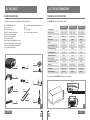
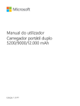
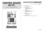
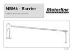
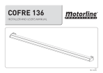
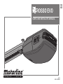
EN
ROSSO EVO
USER'S AND INSTALLER'S MANUAL
v2.1
REV. 11/2014
00. CONTENT
01. SAFETY INSTRUCTIONS
INDEX
STANDARDS TO FOLLOW
01. SAFETY INSTRUCTIONS
ATTENTION:
STANDARDS TO FOLLOW
1B
02. PACKAGE
INSIDE THE PACKAGE
2A
03. THE AUTOMATISM
TECHNICAL SPECIFICATIONS
MANUAL BRAKE RELEASE
REMOVE UPPER COVER
REPLACE UPPER COVER
CHANGING COURTESY LEDS
CHANGING FUSE
PRE-INSTALLATION INFORMATION
2B
3A
3B
3B
4A
4A
4B
04. INSTALLATION
ENGINE’S FIXATION IN THE PIPELINE
THE AUTOMATISM INSTALLATION
INSTALLATION MAP
5A
5B
7
05. PROGRAMMING
LEGEND
MENU FUNCTIONS
PROGRAMMING TRANSMITTERS
8A
8B
11A
06. POST-INSTALLATION
STOPPER AT THE OPENING
STRETCH RAIL CHAIN
MAINTENANCE
• To ensure the safety of people, it is important that you read all the following instructions. Incorrect installation or incorrect use of the product can cause physical injury
and material damage.
• Keep these instructions in a safe place for future reference.
• This product was designed and produced strictly for the use indicated in this manual.
Any other use, not expressly indicated here, could compromise the good
condition/operation of the product and/or be a source of danger.
• ELECTROCELOS SA is not responsible for the improper use of the product,
or other use than that for which it was designed.
• ELECTROCELOS SA is not responsible if safety standards were not taken
into account when installing the equipment, or for any deformation that may occur to
it.
• ELECTROCELOS SA is not responsible for the safety and proper operation
when using components not sold by them.
• Do not make any modifications to the operator components and / or their
accessories.
• Before installation unplug the automatism from the source of power.
• The installer must inform the client how to handle the product in case of
emergency and provide this manual to user.
• Keep remote controls away from children, to prevent the automated
system from being activated involuntarily.
• The customer shall not, under any circumstances, attempt to repair or tune
the operator .Must call qualified technician only.
• Connect the automatism to a 230V plug with ground wire.
• Operator for indoor use.
11B
12A
12A
07. DIAGNOSIS
CONNECTING ENGINE TO 24V BATTERY
12B
08. TROUBLESHOOTING
INSTRUCTIONS FOR FINAL CONSUMERS
INSTRUCTIONS FOR TECHNICAL PERSONNEL
13
13
09. CENTRAL CONNECTIONS
ROSSO EVO CENTRAL
14
EN
EN
02. PACKAGE
03. THE AUTOMATISM
INSIDE THE PACKAGE
TECHNICAL SPECIFICATIONS
Inside the package you will find the following components:
The ROSSO EVO specifications are as follow:
01• 01 ROSSO EVO motor
02• 01 main rod
03• 01 secondary rod
04• 02 4-channel transmitters
05• 01 transmitter support
06• 01 mounting bracket
07• 01 unlock string
08• 03 motor’s fixing plate to the rail
09• 01 rail’s fixing plate to the ceilling
10• 01 rail’s fixing plate to the lintel
11• 01 gate’s fixing plate
12• 01 reinforcement plate to gate’s fixing
plate
13• 01 stopper
14• 01 set of fixing accessories
ROSSO EVO 60
ROSSO EVO 100
ROSSO EVO 120
• Power Supply
AC 230V 50/60Hz
AC 230V 50/60Hz
AC 230V 50/60Hz
• Motor's Power
DC24V - 100W
DC24V - 120W
DC24V - 160W
140mm /sec
140mm /sec
140mm /sec
• Noise Level
≤56dB
≤56dB
≤56dB
• Force
600N
1000N
1200N
-20°C a 70°C
-20°C a 70°C
-20°C a 70°C
120°C
120°C
120°C
• Protection grade
IP20
IP20
IP20
• Working frequence
70%
70%
70%
3 minutes
3 minutes
3 minutes
10m²
15m²
18m²
30 transmitters
30 transmitters
30 transmitters
Rolling Code
Rolling Code
Rolling Code
433,92Hz
433,92Hz
433,92Hz
• Velocity
• Operating temperature
• Thermal protection
• Courtesy Light
• Maximum door area
11•
01•
• Memory
04•
• Code Type
12•
• Radio frequency
The automatism ROSSO EVO dimensions are as follows:
08•
13•
359mm
10•
09•
02•
170mm
03•
06•
07•
24
0m
m
01
EN
m
450 m
150mm
215mm
137mm
02
EN
03. THE AUTOMATISM
03. THE AUTOMATISM
MANUAL BRAKE RELEASE
REMOVING TOP COVER
The ROSSO EVO unlocking system is very simple and practical to use. To do so just pull
the lever down (figure 03).
To block simply pull the lever to the original position.
01
05
06
To remove the cover simply insert a small screwdriver into the side holes, and create a
leverage effect to release the indents fittings between the top cover and the body. Then
just remove the cover by lifting it.
02
03
REPLACE TOP COVER
Position 01 • Motor locked
Position 02 • Motor unlocked
← Together with the automatism it is
also provided a string to apply on the
unlock lever, which makes it even a more
practical and comfortable process.
Maximum:
700mm
07
04
08
To replace the cover you must first fit the back as shown in the figure 07. Then simply
turn down the cover and fit the front pressing down. The fittings will automatically
secure the cover.
EN
EN
03. THE AUTOMATISM
04. INSTALLATION
CHANGING COURTESY LEDS
INFORMATION PRE-INSTALLATION
For a correct operation of ROSSO EVO, you must take into account the following
parameters before the installation:
• Read all steps on this manual at least once in order to get acquainted with the
installation and configuration process.
• Make sure the door’s structure is solid and appropriate to be automated.
• Verify that the sectional door has no technical defects, such as friction points /
prison, that may jeopardize the automatism durability.
09
10
• To replace the LED board you must open the top cover and detach the wire of the LED
from the control board. Loosen the screw which secures the LED board to the top cover
and remove it. Now just put the new LED board, screw it, fit the wire in the control board
and close back the cover on the motor.
• Make sure the door is in good condition to install the motor. To do so, raise it
manually to 800mm, 1600mm and 2000mm from the ground. Check if the door
remains suspended in these positions or descending. If the door starts to go up or
down, it means that the springs are not well calibrated.
• Check the surroundings. Carefully evaluate any hazards that may cause material
damage, possible insects contact, infiltration, among others.
• Make sure that the automatism will be connected to a 230V, properly protected
with Ground Wire.
CHANGING FUSE
• Make sure there is adequate protection against short-circuits / power surges and
earthed in the Electrical Box.
• Be careful when handling directly the control board. Improper handling can
damage some electrical components.
• Make sure you have all the necessary material prepared for installation.
• Evaluate the safety devices to be installed. This will ensure that unexpected
accidents do not happen.
11
12
• To replace the fuse, first loosen it as visible in the image 11. Then just pull to remove it
(image 12). Repeat the same steps in reverse order to put a new fuse.
The operator uses a 250V 2,5A.
EN
It is very important that these precautions are respected!
Only in this way the correct functioning and automatism durability can be achieved!
EN
04. INSTALLATION
04. INSTALLATION
FIXING THE MOTOR IN RAILS
AUTOMATISM INSTALLATION
With standard rails, you can only automate doors with maximum height of
2400mm.
100-150mm
DETAIL 13
125-175mm
15
16
01 • Attach the rail’s support plate to the lintel, as visible in the image 15. In the image
16 if can be seen the distance to keep between the gate rail and support plate’s upper
part (125-175mm).
13
← Note • If you are unable to fix the
rail to the ceiling for not respecting
the measures above, there should
be created a solid structure to be
able to fix the motor in correct
measurements. This structure may
be fixed to the ceiling as a visible
on the image 17.
CEILLING
01 • The steel rail and automatism attachment must be made using the plates and M6
nuts as shown above. Fasten 4 screws, leaving the two in the middle free.
DETAIL 14
17
14
← Support
02 • The aluminum rail and automatism attachment must be made using the plates and
M6 nuts and as shown above. Tighten 4 screws, leaving the two in the front free.
EN
18
02 • Fasten the rail in the fixation plate already attached. To facilitate the task, you can
do it with the rail inclined (motor on the floor / support) which facilitates the installation
since you only have to handle the area of rail to be fixed.
EN
04. INSTALLATION
04. INSTALLATION
AUTOMATISM INSTALLATION
AUTOMATISM INSTALLATION
DETAIL 19
19
23
22
03 • Place celling rail ‘s fixation plate roughly halfway through the steel rail as visible
in the pictures above.
05 • After rising the rail and mark the holes, you should fix the plate with screws.
After that, you should use bracket to reinforce the attachment, this time near the motor
(image 23).
04 • Raise up the motor until the rail is
levelled horizontally.
If necessary, you should create a support
structure to a solid surface as shown on
the previous page, so that the rail stays
horinzotally aligned (picture 17).
01
02
Mark the holes in the ceiling plate and
/ or structure and make the necessary
holes to fix it.
03
04
24
06 • Attach the plates to the top of the
door panel. The rods must be centered
horizontally with the panel so that it stays
aligned with the rail.
It should also be to fixed as higher as
possible (picture 24).
20
21
EN
EN
25
07 • Now attach the two connecting rods
between the trolley and the panel’s upper
plate.
Use the screws and M8 nuts to tighten 2
rods together ( 02 and 03 ), and 2 pins with
pegs to fix them on the trolley and the gate
( 01 and 04 ).
04. INSTALLATION
INSTALLATION MAP
06
28
02
27
07
10
08
09
26
26
05
02
27
04
03
03
01
28
LEGEND:
01 • ROSSO EVO Motor
02 • Steel rail
03 • Rail to ceilling’s/struture’s fixation plate
04 • Bracket for structure fixing
05 • Fast rail to ceilling’s/struture’s fixation plate
06 • Trolley with unlocking system
07 • Rail to lintel’s fixation plate
08 • Connection arm between trolley and gate
09 • Fixation rod to the gate
10 • Shaft and sectional door springs
29
EN
05. PROGRAMMING
05. PROGRAMMING
MENU FUNCTIONS
LEGEND
Legend:
The control board has a main menu which allows access to all the different settings of
the automatism.
• Display
• Main Menu
• Programming transmmiters
• Up
• Down
When you turn the power on, the LCD displays a countdown from 99 to 11, and the
courtesy lamp stays on for 2 seconds. When the motor is in standby, the display shows
the message
.
When the motor is opening, the display always shows the message
When the motor is closing, the display always shows the message
.
• Programming opening and closing courses
• Programming the automatism force level
• Enable/disable safety photocells
• Programming the self-closing feature
• Enable/disable condominium function
• Programming maintenance warnings
• Programming transmitters using already configured transmitters
• Counting of maneuvers
• Enable/disable the service door
.
Note: If you connect a signaling lamp, this will blink during any gate’s movement cycle.
Start all the programs from the stand-by mode (--)!
All the menu configuration instrution in this manual have been performed using as
starting point the stand-by mode (--).
Begin programming the P1 menu with the gate closed, since the first maneuver configuration will be the opening.
• Programming opening and closing courses
Conector Links:
1 • Pedestrian Gate (NC contact)
2 • PB (contact NO)
3 • PE (contact NC)
4 • GND (common)
5 • +24V
6 • Extern Lamp (max. 24V 5W)
3
12
45
01 • Press the M key for 4 seconds to enter the programming menu.
02 • The display will show P1 and press the M key for 2sec to enter the submenu.
03 • The display will show OP and you can now set the opening limit using the or keys
to adjust it.
04 • Press the M key for 2sec to confirm the opened position.
05 • The display will show CL and you can now configure the closing limit using the
same
or keys.
06 • Press the M button for 2sec to confirm the closed position. The control board saves
the configuration and exits the programming mode.
The LEDs light up for 2sec and the gate starts to open and close automatically to the
programmed limits showing the message OP during the opening and CL during the
closing. When it finishes closing, the control board will exit to the stand-by mode (--).
6
If it stays more than 20sec without pressing any key, the control board will exit every
programming and automatically go to stand-by mode (--) without saving any action.
30
EN
EN
05. PROGRAMMING
05. PROGRAMMING
MENU FUNCTIONS
MENU FUNCTIONS
• Programming the automatism force level
• Programming the self-closing feature
01 • Press the M key for 4 seconds to enter the programming menu.
02 • The display will show P1 and press and keys repeatedly until it shows P2.
03 • Press the M key once to access this submenu.
04 • The display will show a value between F1 and F9, which identifies the strength
level when the motor is configured. Use the
or
keys to select the desired option,
being F1 the minimum force and F9 the maximum.
05 • Press the M key once to save this option.
06 • The control board will exit to standby mode (--) and the configuration is complete.
01 • Press the M button for 4 seconds to enter the programming menu.
02 • The display will show P1 and press and keys repeatedly until it shows P4.
03 • Press the M key once to access this submenu.
04 • The display will show a value between 00 and 90, which identifies the time in
seconds that the engine is on hold since the opening ends until start automatic
closing. Use the
or
buttons to select the desired option.
05 • Press the M key once to save this option.
06 • The control board will exit to standby mode (--) and the configuration is complete.
Nota • The control board comes with the F4 level configured from the factory.
Note • The option 00 disables the automatic closing, so the gate will only close if it
receives an order from a configured device.
Any other option sets the automatic closing time, being the minimum 10 seconds
(option 10) and the maximum 90 seconds (option 90).
• Enable/disable safety photocells
01 • Press the M button for 4 seconds to enter the programming menu.
02 • The display will show P1 and press and keys repeatedly until it shows P3.
03 • Press the M key once to access this submenu.
04 • The display will show the value H0 or H1, which identifies the option in which the
central is configured. Use the or keys to select the desired option.
H0 disables the use of photocells and H1 activates it.
05 • Press the M key once to save this option.
06 • The control board will exit to standby mode (--) and the configuration is complete.
Functionality • When the use of photocells is active and some obstacle cross them
when the door is closing, the door will reverse direction beginning to open.
Note • The use of photocells comes disabled by the factory (H0).
Start all programs from the stand-by mode (-)
• Enable/disable function condominium
01 • Press the M button for 4 seconds to enter the programming menu.
02 • The display will show P1 and press and keys repeatedly until it shows P5.
03 • Press the M key once to access this submenu.
04 • The display will show the value H0 or H1, which identifies the option in which the
central is configured. Use the or buttons to select the desired option.
05 • Press the M key once to save this option.
06 • The control board will exit to standby mode (--) and the configuration is complete.
Functionality • This function causes the central to ignore all orders for the opening
course sent by configured devices.
• If you press the transmitter during the opening, the order is rejected and it continues
to open
• If you press with the door completely open, it will begin to close.
• If you press during closing, the gate reverses direction and starts to open.
When disabled, you can control the opening or closing of the gate whenever you want,
and their behavior is open-stop-close-stop-open (...) by each time you press the
transmitter.
If it stays more than 20sec without pressing any key, the controlboard will exit the
state and will automatically go to stand-by mode without saving any action.
EN
Note • The P4 and P5 functions, when activated, prevent the gate to stay open. This
way the gate will always open completely, starting the closure after the pause time
defined in P4.
EN
05. PROGRAMMING
05. PROGRAMMING
MENU FUNCTIONS
MENU FUNCTIONS
• Programming maintenance warnings
• Counting maneuvers
01 • Press the M key for 4 seconds to enter the programming menu.
02 • The display will show P1 and press and keys repeatedly until it shows P6.
03 • Press the M key once to access this submenu.
04 • The display will show a value between 00 and 45, which identifies the thousands of
maneuvers to which the motor will emit a warning maintenance light.
Use the or keys to put on the desired option.
05 • Press the M key once to save this option.
06 • The control board will exit to standby mode (--) and the configuration is complete.
Funcionality • This notice serves to schedule revisions to the automatism, gate or
springs after a certain number of complete maneuvers (open-stop-close-stop). When
the automatismo completes the number of maneuvers defined by this menu, the LEDs
will blink during 2 minutes after every maneuver, to emit the maintenance warning.
Note • The option 00 disables the maintenance warning. Any other option defines
thousands of operations, the lowest value is 5000 operations (option 05) and the
maximum is 45000 operations (option 45).
Whenever you want to reconfigure this option, you must perform two configurations.
First, set the option to 00 to make a RESET to the counting maneuvers. After that, make
a new one setting the new desired option. The central will, from this moment on, start
counting maneuvers to emit the maintenance warning.
• Programming transmitters using already configured
transmitters
01 • Press the M key for 4 seconds to enter the programming menu.
02 • The display will show P1 and press and keys repeatedly until it shows P7.
03 • Press the M key once to access this submenu.
04 • The display will show the value L0 or L1, which identifies the option in which the
central is configured. Use the or keys to put on the desired option.
05 • Press the M key once to save this option.
06 • The control board will exit to standby mode (--) and the configuration is complete.
Funcionality • This menu allows you to enable or disable the possibility to program a
new transmitter through one already configured (see page 11.A).
L0 means that this functionality is disabled, and L1 means that is enabled.
EN
01 • Press the M key for 4 seconds to enter the programming menu.
02 • The display will show P1 and press and keys repeatedly until it shows P8.
03 • Press the M key once to access this submenu.
04 • The display will show three numbers, each one for 2 seconds separated by
intervals of 1 second between them.
After this the control board will automatically exit to standby mode (--).
Funcionality • This function serves only to show all completed maneuvers performed
by the automatism (open-stop-close-stop). Just put together the three numbers
shown on the display and you will know the total maneuvers of that engine.
Example: If when entering the P8 submenu the display first show nº15, then nº65 and
finally nº22, means that a total of 156522 complete maneuvers have already been
done.
RESET through the menu P6: To restart maneuver counting, go to P6 submenu, and
while the display shows any of the options in this submenu, press the and keys
simultaneously for 10seconds. The control board will automatically exit to standby
mode and the RESET to the P8 menu is complete.
• Enable / disable the service door
01 • Press the M key for 4 seconds to enter the programming menu.
02 • The display will show P1 and press and keys repeatedly until it shows P9.
03 • Press the M key once to access this submenu.
04 • The display will show the value E0 or E1, which identifies the option in which the
central is configured. Use the or keys to put on the desired option.
05 • Press the M key once to save this option.
06 • The control board will exit to standby mode (--) and the configuration is complete.
Funcionality • The E0 disables the use of the service door while the E1 option activates
it.
When activated this function, the controlboard will only make any opening or closing
maneuver if the service door is closed.
If the door is opened, the controlboard will reject any opening or closing order.
EN
05. PROGRAMMING
06. POST-INSTALLATION
PROGRAMMING TRANSMITTERS
1
2
1
4
4
STOPPER AT THE OPENING
2
3
The automatism needs a stopper in the opening and closing to always control the
courses. In closing maneuvers, the ground will be the stopper for the gate, but in the
opening maneuvers it is necessary to create a stopper on the steel rail, to ensure that
the trolley always stop in the correct place.
1
2
3
4
3
[MX4SP]
31
[MXS4SP]
32
33
[MX5SP]
• Standard configuration using the T key on the display
01 • In stand-by mode (--) press the T key until the display shows SU.
02 • Press one time the transmitter’s desired key to configure until the engine starts
moving.
Note • Repeat these steps whenever you want to configure new transmitters.
34
35
• Configuration through already configured transmitters
Since there is already configured transmitter, you can use it to open the control board’s
memory by distance in order to configure new transmitters.
This allows easy configuration without requiring direct access to the engine.
01 • In Stand-By mode (--) press 2 and 3 keys from an already configured transmitter
until the courtesy LEDs start to blink. Now release the pressed buttons.
02 • Press the new transmitter’s desired key to configure until the automatism starts
moving.
Note .1 • Repeat these steps whenever you want to configure new transmitters.
Note .2 • This feature can be enabled or disabled via the P7 menu (see pag 10.A).
• Delete all configured transmitters
36
• To install the opening stopper just apply it on the rail, as seen in Figure 34.
The stopper must have a metal plate out of the rail and other on the inside, so when you
fasten it, this is secure in the pipeline.
• With the door completely open, push the stopper untill it touches the trolley (35).
• Fasten the two screws to hold the stopper in that exact position (36).
01 • In stand-by mode (--) press the T key for 10sec until the display shows dl.
The control board has a maximum capacity of 30 transmitters and only
accepts Motorline Rolling Code transmitters!
EN
EN
06. POST-INSTALLATION
07. DIAGNOSIS
STRETCH RAIL’S CHAIN
CONNECT ENGINE TO 24V BATTERY
DETAIL 39
37
For a correct automatism function, the chain has to be very well adjusted.
For that, you just need to tighten or loosen the shadowed nut in the above picture with
a wrench key, which will stretch or relieve the chain.
The chain can’t be too much stretched, or it will get too stuck and damage the gear and
the motor, nor too loose to the point of creating a sag in the middle and come out of
the rail.
Note • The spring tensioner should never get fully compressed, because it means that
it is on is maximum tension!
39
In case of automatism failure or malfunction, you must detect the fail component (motor
or central). To do that, you should test the motor directly connected to a 12/24V DC power
source, in order to understand if this works.
Just disconnect the two motor cables (shaded in the image 39) which connect to the
central and connect them directly to a 12/24V DC battery as visible in the image 40.
MAINTENANCE
40
38
The only maintenance required is lubricating the automatism and rail motion axes. The
pinions at both ends of the rails as well as their supporting bearings and chain should
be lubricated at least once every year.
EN
Motor cables have no specific way of connection. The only difference is that if you
connect the motor in one way, it will rotate in one direction, and if you connect the wires
in the oppose it will rotate in the other direction.
EN
08. TROUBLESHOOTING
INSTRUCTIONS FOR FINAL CONSUMERS
Anomaly
• Motor does
not work
• Motor does
not move but
makes noise
Procedure
Actions
INSTRUCTIONS FOR TECHNICAL PERSONNEL
Procedure II
Discovering the origin of the problem
1 • Remove the top cover of the
engine;
2 • Measure the 24V
transformer’s output to detect
the location of the malfunction;
A) Has 24V:
1 • Make sure the central is
supplying the motor to detect
whether the fault is in the engine
or in the central. Replace the
damaged component or send to
Motorline facilities for diagnosis
and repair.
• Consult a MOTORLINE
qualified technician.
1 • Give a start on the transmitter
to open and check the LEDs
behavior.
2 • If it blinks twice, then the
connection with the photocells
is having problems. Check all the
photocells circuit connection.
3 • If it flashes three times, then
the service door connection is
having problems. Check all the
door’s connection circuit.
• Encountered any
problems?
• Consult an gate’s technician.
1 • Check all the motion axes and the movement systems associated to the gate and the automatism (rails,pulleys, bolts, hinges, etc.) to find
out he problem. Also make sure the springs are in good condition and are able to withstand the gate.
• The gate moves
easily?
• Consult a MOTORLINE
qualified technician.
1 • Turn off the central’s motor
and test it directly connected
to a 24V battery to find the
malfunction (see page 12.B)
• Consult a MOTORLINE
qualified technician.
1 • Make sure the display and the courtesy
LEDs are connected and to see if it has power;
2 • Go to the menu on the display and disable
the photocells and the service door;
3 • Try to close;
• Verify that you have
connected to 230V
power to the automation and if the fuse is
working properly.
• Still not working
• Make sure the pedestrian service door
is securely closed.
• Still not working
• Unlock the engine
and move the gate
manually to check for
mechanical problems
on the gate.
• Motor opens 1 • Check if there is
• Gate has opened
but does not
any obstacle in front
but did not close.
close
of the photocells;
2 • Check if any of the
gate’s control devices
(key selector, push button, video intercom,
etc.) are locked and
sending permanent
sign;
• Consult a MOTORLINE
qualified technician.
2 • If the engine operate, the
problem is in the central.
Pull it out and send it to the
MOTORLINE technical services
for diagnosis;
B) Doesn’t have 24V:
1 • Check the 230V transformer
input. If you can measure 230V
on the input, the transformer is
the problem. If not, the problem
is the fuse, electrical cables or
electrical current itself. Check all
systems.
3 • If the motor does not work,
remove it and send it to the
MOTORLINE technical services
for diagnosis.
A) It closed:
1 • Problem is in one of these two systems.
Activate the photocells and make sure the
gate closes. If it closes, the problem will be
on the service door. Activate it from the menu
and try to close the gate to be sure.
B) Didn’t close:
1 • The problem is in the motor or in the
central.Give the order to close the gate while
measuring the output power from the central
to the engine.
If you have 24V, the center is working and the
problem is in the engine.
2 • If it does not have power, the problem
remains in the centralboard.
NOTE • With the gate open, if you give the order to close and you have some
obstacle in front of the the photocells, LEDs blink twice.
During closing, if it invert for stress detection, blink once.
• Motor does
not the full
itinerary
• Unlock motor and
move gate by hand to
check for mechanical
problems on the gate.
• Encountered any
problems?
• Consult an gate’s technician.
1 • Check all the motion axes and the movement systems associated to the gate and the automatism (rails,pulleys, bolts, hinges, etc.) to find
out he problem. Also make sure the springs are in good condition and are able to withstand the gate.
• Is the gate moving
easily?
• Consult a MOTORLINE
qualified technician.
1 • Verify that the gate tests were
well done;
2 • Change the force on P2 menu
until the engine move the gate
without changing direction;
3 • This adjustment must be
made so that the gate when
meeting an obstacle inverts his
direction (left illustration);
4 • If even at his maximum
strength (F9) the problem still
remains, test the motor directly
connected to a 24V battery to
see if it has the strength to open/
close the door completely;
5 • Change the force on P2 menu
until the engine moves the gate
without changing direction;
EN
09. CENTRAL CONNECTIONS
ROSSO EVO CONTROL BOARD
Pedestrian Door
Pushbutton/Key
Selector
Photocells
DV 12/24V COM
NC
Lightbulb
DV 12/24V
or
~ ~
~ ~
24V
5W máx
External Receiver
12/24v
0v
CH1-a
CH1-b
CH2-a
CH2-b
Outdoor Antenna
MR5
Courtesy
LEDs
4 5 6
1 2 3
230V
Power Supply
CON1*
Battery 12/24V
GND
Recetora
433,92Hz
ANT
Encoder
1 2
DISPLAY
BOARD
CONTROL
BOARD
Transformer
IN:230V OUT:24V
Fuse
2.5AL 250V
Earth wire
MOTOR
(máx 240W)
*CON1:
1 • Pedestrian door
2 • PB
3 • PE
4 • GND
5 • +24V (máx: 1,5W)
6 • FLASH (máx: 24V 5W)
41
EN