1
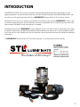
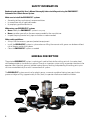
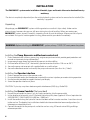
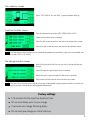
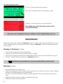
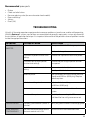
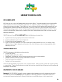
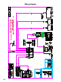
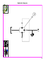
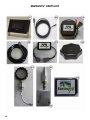
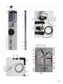
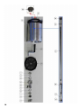
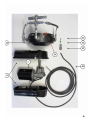
USER MANUAL
Installation and Operating Instructions
Envirosys®
Automatic Bar & Chain Grease System
for Logging Equipment
Increase Productivity
Reduce Operating Costs
Complete Elimination of Chain Oils
SAVE THESE INSTRUCTIONS FOR FUTURE REFERENCE!
The maker of Envirosys®
Version 6 - June 2014
TABLE OF CONTENTS
1. Introduction............................................................................................................................................. 1
2. Safety information.............................................................................................................................. 2
3. General description............................................................................................................................. 2
4. Specifications............................................................................................................................................ 3
5. Installation............................................................................................................................................... 4
6. Getting Started....................................................................................................................................... 5
7. OPERATING..................................................................................................................................................... 6
8. Maintenance.............................................................................................................................................. 8
9. Troubleshooting.................................................................................................................................... 9
10. Warranty.................................................................................................................................................... 10
11. APPENDIX....................................................................................................................................................... 11
a) Declaration of Incorporation.................................................................................................................
b) Grease Technical Data............................................................................................................................
c) Updating the Envirosys® Software......................................................................................................
d) Wiring Diagram.........................................................................................................................................
e) Hydraulic Diagram...................................................................................................................................
f) Parts List.....................................................................................................................................................
g) Electronic Control Unit Diagram..........................................................................................................
12
13
15
20
21
22
28
INTRODUCTION
CONGRATULATIONS! You have just invested in the next generation of lubricating technology for your
logging equipment. Your purchase ensures years of clean, reliable and highly cost-effective operations. We
trust that you will appreciate the quality of our ENVIROSYS® Automatic Bar & Chain Grease System.
Please read this manual in its entirety. Its purpose is to familiarize you with your ENVIROSYS® system, safe
installation, proper operation and maintenance. It contains information that is useful to you now, and in the
years to come. So keep it handy and refer to it as needed.
The performance of your ENVIROSYS® system depends of many variables. Since all installations are unique,
the general information and operating procedures presented here can only serve as useful guidelines rather
than hard and fast rules. Should you have any questions, do not hesitate to contact your dealer for additional
information.
The ENVIROSYS® Automatic Bar & Chain Grease System is manufactured and warranted by:
The maker of Envirosys®
208, rue du Parc Industriel
St-Prime (Quebec) G8J 2B1
CANADA
Phone: + 1 418-251-1218
Fax:
+ 1 418-251-1364
[email protected]
www.envirosysforest.com
1
SAFETY INFORMATION
Read and understand this User’s Manual thoroughly before installing and using the ENVIROSYS®
Automatic Bar & Chain Grease System.
Make sure to install the ENVIROSYS® system:
• According to the manufacturer’s recommendations
• In accordance with all applicable codes
• By employing qualified technician
When using your ENVIROSYS® system:
• Never modify the ENVIROSYS® system in any way
• Never use other grease than the ones recommended by the manufacturer
• Inspect the pump, control unit, pipes and cables as recommended
Other safety guidelines:
• Always use the necessary personal protective equipment
• Install the ENVIROSYS® system in a place where re-filling the reservoir with grease can be done without
risk of slipping and/or falling down
• Clean the ENVIROSYS® system as needed
GENERAL DESCRIPTION
The patented ENVIROSYS® system is replacing oil used to lubricate the cutting parts of a harvester head
with biodegradable or standard chain grease. Through an ingenious system using an operator interface in the
operator cabin, the chain grease is injected under pressure, reaching and protecting the cutting parts up to
six times more effectively than with a conventional oil system.
The ENVIROSYS® system consists of an electric pump, a reservoir capable of storing two special chain
grease cartridges of 2 kg (approximately 4.4 lbs) each, an operator interface and electrical cables.
Grease Pump
Operator
Interface
Electronic
Control Unit
12 VDC to 24 VDC
converter
2
Grease
Reservoir
Chain Grease
Cartridge
Electrical
cables
SPECIFICATIONS
Weight (empty)
Dimensions (Height x Diameter)
Operating temperature
Voltage
11 kg
24,2 pounds
45 x 30 cm
18 x 12 inches
-30 °C to + 80 °C
-22 °F to +175 °F
12 or 24 Volts DC (specify when ordering)
Power (maximum)
Reservoir capacity
Grease characteristics
50 Watts
Approx. 5 kg
Approx. 11 lbs
Standard or Biodegradable
See Technical Data Sheet in Appendix
Principal Components and Features:
Grease Pump
• Available for 12 VDC or 24 VDC electrical systems
• Pistons type activation for highly efficient grease delivery
• Relief and check valves to prevent overpressure and backflows
Grease Reservoir
• Specially designed to connect with our special cartridges (accordion type) to minimize risk of grease
contamination when refilling
• Uses grease agitator for maximum efficiency
• Low level sensor to help preventing unexpected shut-downs
Grease Cartridges
• Developed in our laboratories for the sole use of the ENVIROSYS® system
• Each cartridge weighs 2 kg (approximately 4.4 lbs) and is available in boxes of four units each
• Available in two types – highly adhesive standard and biodegradable chain greases - for both summer
and winter conditions
Operator interface
• Touch screen capability
• Uses to oversee and control the chain grease lubrication process
• Allows flow rate control for optimum lubrication
• Warning light and audible alarm to indicate time for refilling
• Control up to two saws and one roller equipment
• Use to upgrade software version from a SD card
Electronic control unit
• Contains state-of-the-art controller to oversee all operations
• Contains necessary electric protective fuses
Electrical Cables and Converter
• All pre-wired and numbered cables for easy installation
• 12 to 24 VDC converter available upon request (included with 12 VDC system)
3
INSTALLATION
The ENVIROSYS® system can be installed on all models, types and brands of harvester head and forestry
machinery.
The device is completely independent from the existing hydraulic systems and can be removed and re-installed if the
machinery is upgraded.
Unpacking
We package your ENVIROSYS® system with the greatest care so that it ships safely. Under certain
circumstances, however, damage can still occur during transit and handling. When you receive your
ENVIROSYS® system, unpack it carefully, inspecting it and all parts for damage. Also ensure that all parts
are included. If any parts are damaged or missing, please contact your dealer immediately.
WARNING: Before installing the ENVIROSYS® system, always TURN OFF main power to system.
Installing the Pump, Reservoir and Electronic control unit
1. Find a protected area with easy access (e.g.: engine compartment which provide good protection and
warmer environment during cold weather)
2. Leave enough space above and around the reservoir to allow refilling
3. Drill two holes of 10mm (3/8”) horizontally (center to center distance = 120 mm or 4¾”)
4. Secure the pump and reservoir with supplied bolts on a solid surface
5. Secure the electronic control unit nearby the pump and reservoir (less than 1m / 3 feet)
Installing the Operator interface
1.
2.
3.
4.
Find an appropriate space in the operator cabin
Ensure reachable access for the operator to control the various injection parameters during operation
Use the bracket provided to support the touch pad display
Screw the operator interface in place
CAUTION: Try to stay away from electromagnetic interference (EMI) (e.g.: Radio FM)
Installing the Grease Conduits (Not provided)
1. Use existing oil conduit or hose, if any, by simply connecting it to the pump outlet
2. In the absence of oil conduit, use ¼” diameter hydraulic quality hose (approx. 6.35 mm) equivalent to
SAE 100 R2AT / DIN EN 853 2SN (400 bar / 5800 psi)
3. Install the conduit along the hydraulic lines on the boom of the harvester machine - from the main unit
to the saw bar. The feeding line installation should take into consideration boom configurations (i.e.
telescopic or extendable masts)
4. Connect the conduit to the pump unit and to the saw bar using JIC female swivel 04 type fittings
whenever possible
4
NOTE:
A larger hose diameter does not provide any advantages or disadvantages. Each 10-metres (33 feet) length
of ¼” diameter hose section corresponds to a volume of 1300 cc or approximately 1.3kg of grease.
Some harvester head models (Supercut) specify a maximum 50 bar pressure in order to avoid gasket
damage. In these cases, a pressure-reducing valve has to be installed (from 300 to 50 bars) near the
saw block to avoid exceeding the prescribed standard. This pressure reducing valve is available in the
ENVIROSYS® system parts list.
Installing the Electrical Cables
1. Connect the pump unit (#5 and #6) to the electronic control unit (#8) using the pre-assembled cable
2. Connect the operator interface to the electronic control unit using the pre-assembled cable (#1)
3. Identify and connect the saw signal (positive or negative) to the control unit (#3). If no signal is available
in the cabin, the signal will have to be brought from the saw unit located on the head. It is recommended
that the signal be identified by the manufacturer
4. Connect the electronic control unit to the main power source/ Key Relay (#2)
IMPORTANT NOTE: Your Envirosys® system must be ordered adequately to match your available electrical
system (i.e. 12 VDC OR 24 VDC).
Note that a 12 to 24 VDC converter unit is available upon request. The attached wiring diagram in appendix
can also be used in support to installation
GETTING STARTED
1. Start by manually filling the supply hose with Envirosys® grease. Use a manual grease pump, not the
Envirosys® system for now
2. Fill up the reservoir by adding two Envirosys® 2kg chain grease accordion cartridges
3. Power up the Envirosys® system by turning ON your equipment start key
• The right operation of the Envirosys® system will be confirmed when the operator interface turn
“ON”
4. Press the “Initial Load” button
5. Verify that grease is coming out of the lubrication channel on the saw unit
6. You are now ready to do what you are doing best, harvesting!
NOTE: The Envirosys® system comes with factory setting grease injection parameters. All parameters can
be modified by the operator at any given time. Please refer to the “OPERATING/Programming” section of
this user manual for more detail.
5
OPERATING
Filling the system with grease
1. Unscrew the reservoir lid
2. Take a 2kg grease accordion cartridge and connect it to the top
of the reservoir
3. Press it down to empty the cartridge
4. Put the reservoir lid back in place
Clean prior to refill & do not overfill
Safety advice: We recommend the use of protective gloves & glasses when
refilling
Note: Always clean the area around the lid before open to prevent debris from
falling into the tank when filling the system.
Programming the Operator interface
Home Page
The version of your software appears here
6
Saw selection screen
Press “SEC SAW #1, #2 and AUX”, grease injection settings.
Injection duration screen
Press the desired time button (SEC SAW#1,#2 or AUX)
Select new duration time in seconds
Press the left arrow to confirm and return to the previous screen
Press the right arrow to access the pre-charge injection screen
NOTE: The injection duration period may vary according to operation conditions, type and size of wood, and
chain saw types (.404 vs ¾” pitch)
Pre-charge injection screen
Adjust the time for which the saw can stay inactive without precharge
Adjust the pre-charge duration time in seconds
Adjust the start-up pre-charge duration time in seconds
Press twice the left arrow to return to the main screen
NOTE: The pre-charge functions are used to ensure non-interruptible supply of grease to the saw chain unit
following grease pressure drop due to idling period of operation.
Factory settings
1.75 seconds for the injection duration time
30 seconds delay prior to pre-charge
2 seconds pre-charge following delay
20 seconds pre-charge on initial start-up
7
Numeric keypad screen
Use this numeric keypad to change settings
Press the arrow button to return to the previous screen
Grease Low Level Alarm screen
Indicates a system fault due to a low level of grease
Note: Adding grease will reactivate the system and this
message will disappear.
Please refer to the “Updating the Envirosys® Software” section in Appendix when necessary
MAINTENANCE
Performing routine actions to keep the Envirosys® system in working order or prevent trouble from arising is
part of a good preventive maintenance plan that will keep your Envirosys® system reliable and performant
for many years.
Cleaning the Envirosys® system
•
•
•
•
Always clean the top of the reservoir before filling
Avoid dirt contamination when manipulating grease cartridges
Clean the air vent passage underneath the black lid on top of the reservoir to allow free flow of grease
DO NOT mix other lubricant or products with Envirosys® greases
Note: Contamination and non-Envirosys® greases usage will void the system warranty
Replacing a piston
• Remove the bottom part of the pump
• Make sure the eccentric shaft is not facing the piston to ease its insertion (the vertical scraper inside the
reservoir must face the piston that will be removed)
• Use the manual override button located on top of the electronic control unit to position the excentric
shaft
• Replace the piston manually in order to avoid damaging threads
• Check for any leak after the installation
8
Recommended spare parts
•
•
•
•
•
•
Pistons
Check and relief valves
Pressure reducing valve (for some harvester head models)
Pipes and fittings
Springs
Fuses (3A)
TROUBLESHOOTING
Virtually all harvester operators experience basic common problems at one time or another while operating.
With the Envirosys® system, most of them are correctable and generally require only a minor adjustment of
the installation, or operation technique. It is important to be aware of the possible causes of problem in order
to take the appropriate actions.
PROBLEM
POSSIBLE CAUSE
SOLUTIONS
NO GREASE BEING
INJECTED
Power off
Turn power ON to the Envirosys® system
Verify and change fuses
Insufficient injection duration time
settings
Increase the injection duration time period
Insufficient pre-charge injection
duration time settings
Increase the pre-charge injection duration
time period
Conduit or hoses disconnected or
leaking
Reconnect conduit and/or hoses
Defective piston
Use manometer to measure pump pressure.
Should read 300 bar (4300 psig). Replace
defective piston.
Relief valve settings too low
Adjust relief valve with a grease manometer
to 300 bar (4300 psig)
Contamination
Verify for contaminants and clean the
system
Air entered the system
Eject it by disconnecting the “T” connector
and bleed the line until grease comes out
FROZEN GREASE
Improper grade selection (winter vs
summer)
Verify for grease hardiness and change grade
PUMP RUNNING
CONTINUOUSLY
The manual override button on the
electronic control unit is ON
Push the manual override button once
Identify and fix the leak
9
WARRANTY
All Envirosys® system components are guaranteed for a two-year (2) period, only if the following rules are
applicable:
• System cleanliness. If solid contaminants are found inside the system, no warranty can be applied
• Mixing other products, different from Envirosys® greases. Since the system has been tested and
validated with our Envirosys® greases, any use of other products voids the warranty
• Any misuse of the system is not covered by the warranty
• If the system is returned to the purchase location for repair; no labour costs will be charged
• All new Envirosys® parts are warranted for a period of three (3) months from the date of delivery;
Note: Contamination and non-Envirosys® greases usage will void the system warranty
Model number:
Unit serial number:
Operator interface serial number:
Date manufactured:
Date purchased:
Technical Support Division
Envirosys® div. of
S.T.L. Lubrifiants
208 Du Parc Industriel
St-Prime (Québec)
Canada
G8J 2B1
Phone: +1 (418) 251-1218
Fax: +1 (418) 251-1364
[email protected]
www.envirosysforest.com
CONTACT YOUR DEALER FOR MORE INFORMATION
10
APPENDIX
11
DECLARATION OF INCORPORATION
According to directive 2006/42/EG, Annex 2B
S.T.L. Lubrifiants
208 Rue de Parc Industriel
St-Prime, Québec, Canada
G8J 2B1
Declare under our sole responsibility that the products:
Grease lubrication equipment for saw chain cutting attachments, Envirosys® 12 VDC or 24 VDC from year
of manufacture 2010 and onwards following the provisions of Directives:
2006/42/EC, Machinery
2004/104/EC, Electromagnetic compatibility (EMC)
to which this declaration relates is in conformity with the following standard(s) or other normative
document(s)
EN ISO 12100-1/A1:2009, -2/A1:2009, EN 60204-1:2006, EN 61000-6-2, EN 55011, EN 61000-6-4
The partly completed machinery must not be put into service until the final machinery into which it is to be
incorporated has been declared in conformity with the provisions of Directive 2006/42/EC.
04 October, 2010
Robert Soucy, chemist
President
S.T.L. Lubrifiants
St-Prime, Québec
Canada
G8J 2B1
Phone:
+1 (418) 251-1218
Fax:
+1 (418) 251-1364
12
GREASE TECHNICAL DATA
BIO LUBRICANTS
BIO lubricants are a family of biodegradable and non-toxic fluids. They were especially formulated to offer
optimal performance for any lubricating application, i.e., hydraulic systems, industrial gears, slide ways,
pneumatic and percussion tools. These lubricants are manufactured with biodegradable vegetable oils and
provide optimal protection for forestry equipment’s, sawmills, slide ways, pneumatic tools and jack drills.
The additive package used is ash less and approved for incidental contact with food (H-1 and H-2). These
lubricants do not affect yellow metals; moreover, they offer superb performance under the most adverse
operating conditions.
All BIO lubricants from S.T.L. LUBRIFIANTS offer the following characteristics:
1.
2.
3.
4.
Superior load carrying capacity and resistance to abrasion
Superior protection against rust and corrosion
Outstanding anti-wear properties and,
Higher resistance to oxidation than most conventional biodegradable lubricants. In addition, these
lubricants form a highly adherent and tenacious film which increases metal surface protection while
reducing stray-mist.
CHARACTERISTICS
All BIO fluids possess the following characteristics:
• Virtually no toxicity.
• Biodegradability higher than 97 %.
• Exceptional anticorrosion, antirust, extreme-pressure and anti-wear properties.
• Excellent oxidation stability and high adherence to surfaces.
• Good low temperature properties.
• Excellent anti-foam properties.
These will be approved by organizations such as NSF and CFIA. Other viscosity grades will also be available
in a near future. Clearly, these lubricants are ideal for industries to which the environment and the welfare of
employees are a concern.
ENVIROSYS® BIO EP GREASE
Envirosys® BIO EP GREASE winter & summer grades are high temperature, multi-purpose greases with
low coefficient of friction. Envirosys® BIO EP GREASE is ideal for applications where there is constant
environmental exposure due to pass through lubrication, unsealed bearings or similar open design.
13
Envirosys® BIO EP GREASE is an industrial grease that is not just rapidly biodegradable and operator safe
but environmentally safe. Envirosys® BIO EP GREASE is made from a vegetable oil carrier. The risk of both
water and soil contaminants is reduced and risk of long and short term liability is minimized. Use Envirosys®
BIO EP GREASE where grease is entering the environment.
ADVANTAGES
• Envirosys® BIO EP GREASE contains no petroleum oil carriers; petroleum based additive packages or
metal additives such as lead or zinc.
• Envirosys® BIO EP GREASE can be used in centralized dispensing system applications where the
potential for environmental contamination is a concern.
• Envirosys® BIO EP GREASE continues to lubricate in the presence of water.
• Envirosys® BIO EP GREASE has an exceptional low coefficient of friction
• Envirosys® BIO EP GREASE has a very high dropping point >343°C (>644°F).
ENVIROSYS® ALC GREASE
Envirosys® ALC winter & summer grades are premium quality, extreme pressure multi-purpose greases and
heavy-duty applications that have a smooth and tacky consistency and is amber in color, up to 325ºF in plain,
anti-friction bearings, slides and way with frequent resupply.
Special extreme pressure additives provide a high load carrying capacity and anti-wear protection. Excellent
water resistance provides bearing protection when water wash-out or leaching conditions are encountered.
Excellent dispensability and pumpability properties make this grease suitable for various methods of
dispensing, including centralized lubrication systems.
Applications and Recommendations:
Excellent shear or mechanical stability, excellent oil retention and good thermal stability make this grease a
prime choice in such applications as: plain and anti-friction bearings - especially where high temperatures
occur; roller and needle bearings; flexible couplings; automotive disc brakes; water pumps; fan bearings,
electric motors, slides and ways where excellent adhesiveness is required.
Envirosys® ALC greases deliver almost as much advantages as our Envirosys® Bio version for the
environment since the volume of lubricant consumed is reduced drastically compared to the old method of
using chain oils.
14
UPDATING THE ENVIROSYS®
SOFTWARE
Step 1: Take off the left side-panel (star-screwdriver)
Step 2: Simply slide the face cover to the left on display.
Step 3: Put the power on
Step 4: Insert the SD card into the slot and push it down until you hear a clic
Step 5: Go to the page setting mode
Step 6: Installing the new program , Select SD PLC , you should see the program on the SD card (FPV9.1). Press download and then OK to confirm that you really want to overwrite the current program.
Next : Change mode from RUN to PROG sure? Press OK. Impossible to write PCE file, no area for PCE
file, Press OK. Completed, Press OK. Change mode from PROG to RUN Sure? Press OK.
Step 7: Back on the screen setting mode
Step 8: Chose SD GT , you’ll see (GT-V.9.1) press on thas and confirm that you want to copy this / really
download ? OK / Copied 100% Press OK
Step 9: Press ESC to come back to the main screen.
Step 10: Remove the SD card and close everything in the reverse order it has been dismanteled
15
16
STEP 1
STEP 1 (2)
STEP 1 (3)
STEP 2
STEP 3
STEP 4
STEP 4 (2)
STEP 4 (3)
STEP 4 (4)
STEP 5
STEP 5 (2)
STEP 6
STEP 6 (2)
STEP 6 (3)
STEP 6 (4)
STEP 6 (5)
17
18
STEP 6 (6)
STEP 6 (7)
STEP 6 (8)
STEP 7
STEP 8
STEP 8 (2)
STEP 8 (3)
STEP 8 (4)
STEP 8 (5)
STEP 8 (6)
STEP 9
STEP 9 (2)
STEP 9 (3)
STEP 9 (4)
STEP 9 (5)
STEP 10
19
Wiring diagram
20
Hydraulic diagram
21
ENVIROSYS® PARTS LIST
22
23
24
25
26
27
Electronic Control Unit Diagram
65
LED1 ON
GREASE LEVEL OK
PUMP MANUAL OVERRIDE
PRESS ONCE PUMP ON
PRESS AGAIN PUMP OFF
FUSE2
VALVE
ATO 3 AMPS
66
LED2 ON
FUSE2 OK
LED3 ON
FUSE3 OK
65
FUSE3
PUMP MOTOR
ATO 3 AMPS
28
PUMP
RELAY
PARTS LIST
POSITION
PARTS NUMBER
QTY
DESCRIPTION
1
SYS001-12
1
MOTOR 12 VDC
1
SYS001-24
1
MOTOR 24 VDC
2
SYS002
3
ADAPTOR
3
SYS003
2
BEARING
4
SYS004
3
PISTON
5
SYS005
1
RELIEF VALVE
6
SYS008
3
SPRING
7
SYS009
1
LOW LEVEL SENSOR
8
SYS010
1
MOTOR COVER
9
SYS011
6
NUT
10
SYS012
6
SLEEVE
11
SYS013
1
HOLDER SENSOR
12
SYS014
1
GREASE FITTING
13
SYS015
3
BOLT
14
SYS016
1
SNAP RING
15
SYS017
1
BUSHING
16
SYS018
2
ALLEN SCREW
17
SYS019
1
RESERVOIR
18
SYS020
8
NUT
19
SYS021
8
WASHER
20
SYS023
4
ANCHORING NUT
21
SYS024
4
THREADED ROD
22
SYS025
1
RESERVOIR LID
23
SYS026
1
NUT
24
SYS027
3
PISTON PLUG
25
SYS028
1
FRAME
26
SYS029
1
NUT
27
SYS302
1
OPERATOR INTERFACE
28
SYS303
1
12VDC TO 24VDC CONVERTER ENVIROSYS®
29
SYS032
2
SNAP RING
30
SYS033
1
BEARING
31
SYS035
1
O RING
32
SYS301
1
CONTROLLER ENVIROSYS®
33
SYS037
1
CROSS ADAPTER
34
SYS039
1
STRAINER
35
SYS042
1
AGITATOR
36
SYS043
1
GROMET
37
SYS045
1
NUT
38
SYS046
1
CAM
39
SYS047
1
FILLING CAP
40
SYS304
1
HARNESS KIT
29
PARTS LIST
POSITION
PARTS NUMBER
QTY
DESCRIPTION
41
SYS048
1’’
STEEL TUBE
42
SYS055
9’’
HIGH PRESSURE HOSE 6 MM I.D. X 8.3 MM O.D.
43
SYS050
3
CHECK VALVE SHORT
44
SYS051
4
SLEEVE 6mm
30
45
SYS052
3
ELBOW 90° 2FP-2MP
46
SYS053
2
ADAPTER FOR SLEEVE 6mm 90° LONG
47
SYS054
2
ADAPTER FOR SLEEVE 6mm 45° SHORT
48
SYS056
1
HYDRAULIC ADAPTOR
49
SYS057
72’’
WIRING PUMP 18/2 SJOOW
50
SYS058
1
CONNECTOR PIN 4
51
SYS059
1
LOCK CONNECTOR PIN RECEPTACLE 4
52
SYS060
1
CONNECTOR PIN 2
53
SYS061
1
LOCK CONNECTOR PIN RECEPTACLE 2
54
SYS062
6
CONTACT PIN 16-18 AWG
55
SYS063
1
ADAPTOR
56
SYS064
1
SHORT HOSE ASSEMBLY
57
SYS065
1
LONG HOSE ASSEMBLY
58
SYS066
1
BONDED SEAL
59
SYS067
1
ELECTRIC ADAPTER
60
SYS068
1
OPERATOR INTERFACE HARNESS
61
SYS006
1
PRESSURE REDUCING VALVE
62
SYS007
1
HYDRAULIC BLOCK
63
SYS099
1
GREASE MANOMETER
64
SYS305
1
SD CARD
65
SYS308
2
FUSE 3AMPS TYPE ATO
66
SYS309
1
PUMP RELAY 8AMPS