1
Modicon M340 with Unity Pro
EIO0000000940 10/2014
Modicon M340 with
Unity Pro
SSI Module BMX EAE 0300
User Manual
EIO0000000940.04
10/2014
www.schneider-electric.com
The information provided in this documentation contains general descriptions and/or technical
characteristics of the performance of the products contained herein. This documentation is not
intended as a substitute for and is not to be used for determining suitability or reliability of these
products for specific user applications. It is the duty of any such user or integrator to perform the
appropriate and complete risk analysis, evaluation and testing of the products with respect to the
relevant specific application or use thereof. Neither Schneider Electric nor any of its affiliates or
subsidiaries shall be responsible or liable for misuse of the information contained herein. If you
have any suggestions for improvements or amendments or have found errors in this publication,
please notify us.
No part of this document may be reproduced in any form or by any means, electronic or
mechanical, including photocopying, without express written permission of Schneider Electric.
All pertinent state, regional, and local safety regulations must be observed when installing and
using this product. For reasons of safety and to help ensure compliance with documented system
data, only the manufacturer should perform repairs to components.
When devices are used for applications with technical safety requirements, the relevant
instructions must be followed.
Failure to use Schneider Electric software or approved software with our hardware products may
result in injury, harm, or improper operating results.
Failure to observe this information can result in injury or equipment damage.
© 2014 Schneider Electric. All rights reserved.
2
EIO0000000940 10/2014
Table of Contents
Safety Information . . . . . . . . . . . . . . . . . . . . . . . . . . . . .
About the Book. . . . . . . . . . . . . . . . . . . . . . . . . . . . . . . .
Part I BMX EAE 0300 Overview . . . . . . . . . . . . . . . . . . . .
Chapter 1 Module Introduction . . . . . . . . . . . . . . . . . . . . . . . . . . . .
General Information about SSI Functions . . . . . . . . . . . . . . . . . . . . . .
General Information about the SSI Module BMX EAE 0300 . . . . . . . .
Physical Description of the SSI Module BMX EAE 0300. . . . . . . . . . .
Characteristics of the SSI Module BMX EAE 0300 . . . . . . . . . . . . . . .
Environment . . . . . . . . . . . . . . . . . . . . . . . . . . . . . . . . . . . . . . . . . . . .
Standards . . . . . . . . . . . . . . . . . . . . . . . . . . . . . . . . . . . . . . . . . . . . . .
Modicon M340H (Hardened) Equipment . . . . . . . . . . . . . . . . . . . . . . .
Chapter 2 SSI Module Installation . . . . . . . . . . . . . . . . . . . . . . . . .
Mounting the SSI Module BMX EAE 0300 . . . . . . . . . . . . . . . . . . . . .
Mounting the BMX FTB 2800/2820 Terminal Block . . . . . . . . . . . . . .
How to Avoid Electromagnetic Interference . . . . . . . . . . . . . . . . . . . .
LED Indicators . . . . . . . . . . . . . . . . . . . . . . . . . . . . . . . . . . . . . . . . . . .
Chapter 3 Inputs/Outputs Specifications. . . . . . . . . . . . . . . . . . . .
Capture Digital Input Characteristics . . . . . . . . . . . . . . . . . . . . . . . . . .
Reflex Digital Output Characteristics . . . . . . . . . . . . . . . . . . . . . . . . . .
Programmable Input Filtering . . . . . . . . . . . . . . . . . . . . . . . . . . . . . . .
Part II SSI Module BMX EAE 0300 Functionalities . . . . .
Chapter 4 Configuration parameters . . . . . . . . . . . . . . . . . . . . . . .
Configuration Screen for the SSI Module BMX EAE 0300 . . . . . . . . .
Chapter 5 SSI Module BMX EAE 0300 Functions . . . . . . . . . . . . .
SSI Interface . . . . . . . . . . . . . . . . . . . . . . . . . . . . . . . . . . . . . . . . . . . .
Modulo and Reduction Functions . . . . . . . . . . . . . . . . . . . . . . . . . . . .
Offset Function . . . . . . . . . . . . . . . . . . . . . . . . . . . . . . . . . . . . . . . . . .
Inverted SSI Direction Function . . . . . . . . . . . . . . . . . . . . . . . . . . . . . .
Multiple Application of Reformatting . . . . . . . . . . . . . . . . . . . . . . . . . .
Capture Function . . . . . . . . . . . . . . . . . . . . . . . . . . . . . . . . . . . . . . . . .
Compare Function . . . . . . . . . . . . . . . . . . . . . . . . . . . . . . . . . . . . . . . .
SSI Status Register . . . . . . . . . . . . . . . . . . . . . . . . . . . . . . . . . . . . . . .
Event Sent To Application . . . . . . . . . . . . . . . . . . . . . . . . . . . . . . . . . .
Output Block Functions . . . . . . . . . . . . . . . . . . . . . . . . . . . . . . . . . . . .
EIO0000000940 10/2014
7
9
11
13
14
15
16
17
18
19
20
21
22
24
27
29
33
34
35
37
39
41
41
43
44
45
46
47
48
49
51
54
55
56
3
Chapter 6 Adjustment . . . . . . . . . . . . . . . . . . . . . . . . . . . . . . . . . . .
Screen for the SSI Module BMX EAE 0300 . . . . . . . . . . . . . . . . . . . . .
Chapter 7 Debugging the SSI Module BMX EAE 0300 . . . . . . . . .
Debug Screen for the SSI Module BMX EAE 0300 . . . . . . . . . . . . . . .
Chapter 8 Diagnostic of the SSI Module BMX EAE 0300 . . . . . . .
Diagnostic Screen for the SSI Module BMX EAE 0300 . . . . . . . . . . . .
Chapter 9 The Language Objects of the SSI Function . . . . . . . . .
9.1 The Language Objects and IODDT of the SSI Function . . . . . . . . . . .
Introducing Language Objects for Application-Specific SSI. . . . . . . . .
Implicit Exchange Language Objects Associated with the ApplicationSpecific Function . . . . . . . . . . . . . . . . . . . . . . . . . . . . . . . . . . . . . . . . .
Explicit Exchange Language Objects Associated with the ApplicationSpecific Functions . . . . . . . . . . . . . . . . . . . . . . . . . . . . . . . . . . . . . . . .
Management of Exchanges and Reports with Explicit Objects . . . . . .
9.2 Language Objects and IODDTs Associated with the SSI Function . . .
General Information . . . . . . . . . . . . . . . . . . . . . . . . . . . . . . . . . . . . . . .
Implicit Exchange Objects for the T_SSI_BMX IODDT . . . . . . . . . . . .
9.3 The IODDT Type T_GEN_MOD Applicable to All Modules . . . . . . . . .
Language Objects of the IODDT of Type T_GEN_MOD . . . . . . . . . . .
9.4 Language Objects and Device DDT Associated with the SSI Function
Device DDT for BMX EAE 0300 Module . . . . . . . . . . . . . . . . . . . . . . .
DDT Description for Explicit Exchange . . . . . . . . . . . . . . . . . . . . . . . .
Part III Quick Start: SSI Module BMX EAE 0300
Implementation Example. . . . . . . . . . . . . . . . . . . .
Chapter 10 Example Overview . . . . . . . . . . . . . . . . . . . . . . . . . . . . .
Example Introduction . . . . . . . . . . . . . . . . . . . . . . . . . . . . . . . . . . . . . .
Application Background . . . . . . . . . . . . . . . . . . . . . . . . . . . . . . . . . . . .
Chapter 11 Hardware Installation. . . . . . . . . . . . . . . . . . . . . . . . . . .
Mounting the Module and the Terminal Block . . . . . . . . . . . . . . . . . . .
Wiring Diagram of the Process . . . . . . . . . . . . . . . . . . . . . . . . . . . . . .
Chapter 12 Configuring the SSI Module BMX EAE 0300 on Unity
Pro . . . . . . . . . . . . . . . . . . . . . . . . . . . . . . . . . . . . . . . . . .
Configuration of the SSI Module BMX EAE 0300 . . . . . . . . . . . . . . . .
4
59
59
61
61
63
63
65
66
67
68
69
71
75
76
77
81
81
83
84
88
91
93
94
95
97
98
99
101
101
EIO0000000940 10/2014
Chapter 13 Programming the Example . . . . . . . . . . . . . . . . . . . . . .
Declaration of Variables . . . . . . . . . . . . . . . . . . . . . . . . . . . . . . . . . . .
Creating the Program . . . . . . . . . . . . . . . . . . . . . . . . . . . . . . . . . . . . .
Transferring the Project between the Terminal and the PLC . . . . . . .
Chapter 14 Diagnostic and Debugging . . . . . . . . . . . . . . . . . . . . . .
Monitor the Application . . . . . . . . . . . . . . . . . . . . . . . . . . . . . . . . . . . .
Index
EIO0000000940 10/2014
.........................................
105
106
107
108
111
111
113
5
6
EIO0000000940 10/2014
Safety Information
Important Information
NOTICE
Read these instructions carefully, and look at the equipment to become familiar with the device
before trying to install, operate, or maintain it. The following special messages may appear
throughout this documentation or on the equipment to warn of potential hazards or to call attention
to information that clarifies or simplifies a procedure.
EIO0000000940 10/2014
7
PLEASE NOTE
Electrical equipment should be installed, operated, serviced, and maintained only by qualified
personnel. No responsibility is assumed by Schneider Electric for any consequences arising out of
the use of this material.
A qualified person is one who has skills and knowledge related to the construction and operation
of electrical equipment and its installation, and has received safety training to recognize and avoid
the hazards involved.
8
EIO0000000940 10/2014
About the Book
At a Glance
Document Scope
This manual describes the hardware and software implementation of SSI (Synchronous Serial
Interface) module BMX EAE 0300 for Modicon M340 PLCs.
Validity Note
This documentation is valid for Unity Pro V8.1 or later.
Product Related Information
WARNING
UNINTENDED EQUIPMENT OPERATION
The application of this product requires expertise in the design and programming of control
systems. Only persons with such expertise should be allowed to program, install, alter, and apply
this product.
Follow all local and national safety codes and standards.
Failure to follow these instructions can result in death, serious injury, or equipment
damage.
EIO0000000940 10/2014
9
10
EIO0000000940 10/2014
Modicon M340 with Unity Pro
Overview
EIO0000000940 10/2014
Part I
BMX EAE 0300 Overview
BMX EAE 0300 Overview
Overview
This part gives an overview of the SSI module BMX EAE 0300 and its technical specifications.
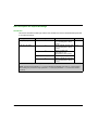
What Is in This Part?
This part contains the following chapters:
Chapter
Chapter Name
Page
1
Module Introduction
13
2
SSI Module Installation
21
3
Inputs/Outputs Specifications
33
EIO0000000940 10/2014
11
Overview
12
EIO0000000940 10/2014
Modicon M340 with Unity Pro
Introduction
EIO0000000940 10/2014
Chapter 1
Module Introduction
Module Introduction
Overview
This chapter gives an overview of the SSI module.
What Is in This Chapter?
This chapter contains the following topics:
Topic
Page
General Information about SSI Functions
14
General Information about the SSI Module BMX EAE 0300
15
Physical Description of the SSI Module BMX EAE 0300
16
Characteristics of the SSI Module BMX EAE 0300
17
Environment
18
Standards
19
Modicon M340H (Hardened) Equipment
20
EIO0000000940 10/2014
13
Introduction
General Information about SSI Functions
Overview Description
The module BMX EAE 0300 is a synchronous serial interface designed for use with an absolute
encoder, it is controlled by the user applications through an open SSI interface.
The position values of the SSI channel are automatically read by the module every fixed period,
unless the channel is disabled.
Available Functions
The following table presents the main functionalities of the BMX EAE 0300 module:
14
Function
Description
Modulo
The modulo function limits the dynamics of the position value within the
power of 2. An event (if enabled) detects the modulo passing. The reflex
output can also be asserted at the passing of modulo (if configured).
Reduction
This function reduces the intrinsic resolution of the encoder by a value
defined by the "reduction" parameter. This reduction is carried out by a
shift in the bit field provided by the encoder.
Offset
The correction function of the encoder offset systematically corrects the
offset produced by the encoder at mechanical position "0". The user
enters the absolute encoder offset parameter.
Capture
The two capture input registers (per channel) enable the PLC program to
carry out a dynamic measurement function between two points. The
capture action can be triggered by two capture inputs. The event will be
triggered at each occurrence of Capture.
Compare
Two independent comparators (per channel), with thresholds that can be
modified by adjustment (explicit exchange), are able to generate an event
or reflex output when the threshold is crossed.
EIO0000000940 10/2014
Introduction
General Information about the SSI Module BMX EAE 0300
Definition
The SSI module BMX EAE 0300 is a 3-channel, synchronous serial interface, absolute encoder
interface for Modicon M340 PLCs.
It supports:
3 channels of SSI inputs
1 reflex output for each SSI channel
2 capture inputs for the 3 SSI channels
8 to 31 bits data width
4 ranks of baud rates (100 kHz, 200 kHz, 500 kHz, 1 MHz)
capture and compare functions
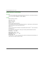
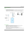
Illustration
The illustration below shows the basic components of an absolute encoder system:
1
2
3
Absolute encoder
Proximity sensors
SSI module BMX EAE 0300
EIO0000000940 10/2014
15
Introduction
Physical Description of the SSI Module BMX EAE 0300
Illustration
The figure below presents the SSI module BMX EAE 0300:
1
2
BMX EAE 0300
28-pin removable terminal block
NOTE: The terminal block is supplied separately.
Required Accessories
The SSI module BMX EAE 0300 requires the use of the following accessories:
28-pin removable terminal block BMX FTB 2800/2820 (see Modicon M340 with Unity Pro,
Analog input/output modules, User manual)
One BMX XSP 0400/0600/0800/1200 electromagnetic compatibility kit (see Modicon M340
Using Unity Pro, Processors, Racks, and Power Supply Modules, Setup Manual)
16
EIO0000000940 10/2014
Introduction
Characteristics of the SSI Module BMX EAE 0300
General Characteristics
This table presents the general characteristics of the SSI module BMX EAE 0300 and
BMX EAE 0300H (see page 20):
SSI Channels
Regular I/O Channels
Maximum SSI Baud Rate
100k, 200k, 500k, 1M
SSI Channel Number
3
Bit Width
8 to 31 bits
Refresh interval
= 1 ms
Number of Digital Inputs
Two 24 Vdc Type 3 inputs per module
Number of Digital Outputs One 24 Vdc output per channel
Hot Swapping Supported
Yes
Encoder Compliance
Absolute encoder 24 V model with standard SSI
interface (tolerance: 19.2-30 Vdc)
Power Supply to Encoder
Voltage: 24 Vdc (Supplied by the field power)
Current: < 200 mA per channel (for 24 Vdc)
Power Distribution To Encoder
Yes, short circuit limited (700 mA total)
Back Plane Power
Consumption
+ 3.3 Vdc
Typical: 150 mA
Maximum: 250 mA
+ 24 Vdc
Not used
Dielectric Strength
Field To Bus
1400 Vdc for 1 minimum
Field Power
Voltage
19.2 to 30 Vdc (24 Vdc typical)
Over-voltage protected up to 45 Vdc.
Current
It depends on the encoder(s) and the load of
reflex output consumption.
For module operating: 30 mA.
NOTE: The encoder is required to have at least 5 mA output current to activate the DATA input of
the SSI module.
WARNING
EQUIPMENT DAMAGE
Do not allow the supplied voltage to exceed the maximum allowed voltage of the encoder when
the module BMX EAE 0300 or BMX EAE 0300H is used to provide power to encoder.
Failure to follow these instructions can result in death, serious injury, or equipment
damage.
EIO0000000940 10/2014
17
Introduction
Environment
Environmental Specifications
All parts are designed:
for the operating range of 0° ... 60 ° C (32° ... 140 ° F).
to operate at an altitude up to 4000 m (13123 ft.).
NOTE: Correction factor for 4000 m (13123 ft.) is 1.29, it is applied to all clearance and
creepage distances.
All parts comply with:
SE Eco design directives.
European RoHS regulation and do not contain lead, mercury, cadmium, hexavalent chromium,
poly-brminated biphenvls (PBB) and poly-brominatedethers.
Chinese RoHS regulation.
SE requirements for reduced product energy consumption during manufacture and use.
the REACH directive.
18
EIO0000000940 10/2014
Introduction
Standards
Agency Certifications
For countrie certifications, all parts are:
CE certified for European countries.
UL certified for U.S.A.
CSA certified for Canada.
C-Tick certified for Australia.
GOST certified for Russia.
For hazardous locations certifications, all parts are:
FM Class1 Div2 certified.
CSA Class1 Div2 certified.
UL Class1 Div2 certified.
ATEX Zone 2 certified.
EIO0000000940 10/2014
19
Introduction
Modicon M340H (Hardened) Equipment
M340H
The Modicon M340H (hardened) equipment is a ruggedized version of M340 equipment. It can be
used at extended temperatures (-25...70ºC) (-13...158ºF) and in harsh chemical environments.
This treatment increases the isolation capability of the circuit boards and their resistance to:
condensation
dusty atmospheres (conducting foreign particles)
chemical corrosion, in particular during use in sulphurous atmospheres (oil, refinery, purification
plant and so on) or atmospheres containing halogens (chlorine and so on)
The M340H equipment, when within the standard temperature range (0...60ºC) (32...140ºF), has
the same performance characteristics as the standard M340 equipment.
At the temperature extremes (-25... 0ºC and 60... 70ºC) (-13...32ºF and 140...158ºF) the hardened
versions can have reduced power ratings that impact power calculations for Unity Pro applications.
If this equipment is operated outside the -25...70ºC (-13...158ºF) temperature range, the
equipment can operate abnormally.
CAUTION
UNINTENDED EQUIPMENT OPERATION
Do not operate M340H equipment outside of its specified temperature range.
Failure to follow these instructions can result in injury or equipment damage.
Hardened equipment has a conformal coating applied to its electronic boards. This protection,
when associated with appropriate installation and maintenance, allows it to be more robust when
operating in harsh chemical environments.
20
EIO0000000940 10/2014
Modicon M340 with Unity Pro
SSI Module Installation
EIO0000000940 10/2014
Chapter 2
SSI Module Installation
SSI Module Installation
Overview
This chapter provides information to install the module.
What Is in This Chapter?
This chapter contains the following topics:
Topic
Page
Mounting the SSI Module BMX EAE 0300
22
Mounting the BMX FTB 2800/2820 Terminal Block
24
How to Avoid Electromagnetic Interference
27
LED Indicators
29
EIO0000000940 10/2014
21
SSI Module Installation
Mounting the SSI Module BMX EAE 0300
At a Glance
Handling the module while the power supply to the rack is turned on does not disturb the PLC.
Installation Precautions
The SSI module may be installed in any of the positions in the rack except for the two slots for PS
and CPU which are reserved for the rack’s power supply module (BMX CPS ••••) and the
processor (BMX P34 ••••) respectively. Power is supplied by the bus at the bottom of the rack
(3.3 Vdc and 24 Vdc).
Before installing a module, you must take off the protective cap from the module connector located
on the rack.
DANGER
HAZARD OF ELECTRIC SHOCK
Disconnect voltage supplying sensors and pre-actuators before plugging / unplugging the
terminal block on the module.
Remove the terminal block before plugging / unplugging the module on the rack.
Failure to follow these instructions will result in death or serious injury.
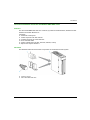
Installation
The diagram below shows SSI module BMX EAE 0300 mounted on the rack:
The following table describes the different elements which make up the assembly below:
22
Number
Description
1
SSI module BMX EAE 0300
2
Standard rack
EIO0000000940 10/2014
SSI Module Installation
Installing the Module on the Rack
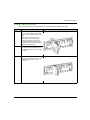
The following table shows the procedure for mounting the SSI module in the rack:
Step
Action
Illustration
1
Position the locating pins situated at
the rear of the module (on the bottom
part) in the corresponding slots in the
rack.
Note: Before positioning the pins,
make sure you have removed the
protective cover from the rack slot
(see Modicon M340 Using Unity Pro,
Processors, Racks, and Power Supply
Modules, Setup Manual).
Steps 1 and 2
2
Swivel the module towards the top of
the rack so that the module sits flush
with the back of the rack. It is now set
in position.
3
Tighten the safety screw to ensure that Step 3
the module is held in place on the rack.
Tightening torque: Max. 1.5 N•m
(1.10 lb-ft)
EIO0000000940 10/2014
23
SSI Module Installation
Mounting the BMX FTB 2800/2820 Terminal Block
Terminal Block
SSI module BMX EAE 0300 requires the BMX FTB 2800/2820 28-pin terminal block to be inserted
into the front of the module. These fitting operations (assembly and disassembly) are described
below.
BMX FTB 2820
BMX FTB 2800
Installing the 28-Pin Terminal Block
CAUTION
TERMINAL BLOCK IMPROPERLY FIXED TO THE MODULE
Follow the procedure instructions to fix the terminal block to the module.
Verify that the screws are tightened.
Failure to follow these instructions can result in injury or equipment damage.
24
EIO0000000940 10/2014
SSI Module Installation
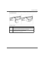
The following table shows the procedure for assembling the 28-pin terminal block onto an SSI
module BMX EAE 0300:
Assembly procedure:
Step
Action
1
Once the module is in place on the rack, install the terminal block by inserting
the terminal block encoder (the rear lower part of the terminal) into the module’s
encoder (the front lower part of the module), as shown above.
2
Fix the terminal block to the module by tightening the 2 mounting screws located
on the lower and upper parts of the terminal block.
Tightening torque: 0•4 N.m (0.29 lb-ft).
EIO0000000940 10/2014
25
SSI Module Installation
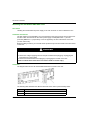
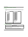
28 Pin Terminal Block Arrangements
The terminal block is arranged as followed:
26
EIO0000000940 10/2014
SSI Module Installation
How to Avoid Electromagnetic Interference
Overview
Electromagnetic perturbations may cause the application to operate in an unexpected manner.
WARNING
UNEXPECTED EQUIPMENT OPERATION
In a highly disturbed electromagnetic environment,
use the BMX XSP 0400/0600/0800/1200 electromagnetic protection kit (see Modicon M340
Using Unity Pro, Processors, Racks, and Power Supply Modules, Setup Manual) (See
Modicon M340 using Unity Pro, Processors, Racks and Power Supply Modules, BMX XSP xxx
Protection Bar) to connect the shielding and
use a stabilised 24 Vdc supply for inputs and a shielded cable for connecting the supply to the
module.
use a shielded cable for capture inputs and reflex outputs if any of them is wired.
use a shielded cable for each SSI channel respectively and note that 24 Vdc and GND must
be included in the shielded cable. (Each shielded cable includes CLK pair, DATA pair, 24Vdco,
0Vdco. If the reflex output is connected to encoder, it also has to be included.)
Failure to follow these instructions can result in death, serious injury, or equipment
damage.
EIO0000000940 10/2014
27
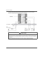
SSI Module Installation
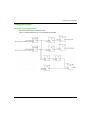
The figure below shows the recommended circuit for a high-noise environment using the
BMX XSP 0400/0600/0800/1200 electromagnetic protection kit:
o
CAUTION
POTENTIAL MODULE DAMAGE - IMPROPER FUSE SELECTION
Use fast acting fuses to protect the electronic components of the module from overcurrent and
reverse polarity of the input/output supplies. Improper fuse selection could result to damage to
the module.
Failure to follow these instructions can result in injury or equipment damage.
28
EIO0000000940 10/2014
SSI Module Installation
LED Indicators
At a Glance
The SSI module BMX EAE 0300 is equipped with LEDs that display the module’s channels status
and detected errors.
Display Panels
LED display:
The first row of LEDs indicates module information:
LED RUN: Indicates the module’s operational status
LED ERR: indicates an internal detected fault in the module or a detected fault between the
module and the rest of the configuration
LED I/O: Indicates an external detected fault
LED DL: Indicates the Firmware download status
The second row of LEDs corresponds to SSI channels.
The LEDs are represented in the following way: (y = 0, 1 or 2 depending on the SSI channel)
LED Sy: Channel y Input
LED Qy: Reflex Output for channel y
LED I0/1: Capture Input for 3 SSI channels
When a voltage is present on an input or output, the corresponding LED is lit.
EIO0000000940 10/2014
29
SSI Module Installation
Diagnostics
The following table allows you to perform diagnostics of the module status according to the LEDs:
RUN, ERR, I/O, DL and channels (LEDs S0 to I1):
Module status
LED indicators
RUN
ERR
I/O
DL
S0
S1
S2
Q0
Q1
Q2
I0
I1
The module is not
receiving power or has
inoperative
The module is
inoperative
The module is not
configured or is
configuring its channels
Module has Lost
communication with
CPU
Field Power Supply
inoperative
Downloading firmware
S0 has a detected line
error
S1 has a detected line
error
S2 has a detected line
error
Qx has a short circuit
Channels are
operational
Legend
LED on
LED off
LED flashing slowly
LED flashing fast
An empty cell indicates that the state of the LED(s) is not taken into account
30
EIO0000000940 10/2014
SSI Module Installation
"Absolute SSI Encoder"
mode is selected and no
error detected
Voltage is present on Q0
Voltage is present on Q1
Voltage is present on Q2
Voltage is present on I0
Voltage is present on I1
An empty cell indicates that the state of the LED(s) is not taken into account
Legend
LED on
LED off
LED flashing slowly
LED flashing fast
An empty cell indicates that the state of the LED(s) is not taken into account
EIO0000000940 10/2014
31
SSI Module Installation
32
EIO0000000940 10/2014
Modicon M340 with Unity Pro
Inputs/Outputs Specifications
EIO0000000940 10/2014
Chapter 3
Inputs/Outputs Specifications
Inputs/Outputs Specifications
Overview
This chapter contains information about the inputs and outputs of the SSI module.
NOTE: The SSI performances described in this chapter are only valid with wired as indicated in
this documentation.
What Is in This Chapter?
This chapter contains the following topics:
Topic
Page
Capture Digital Input Characteristics
34
Reflex Digital Output Characteristics
35
Programmable Input Filtering
37
EIO0000000940 10/2014
33
Inputs/Outputs Specifications
Capture Digital Input Characteristics
Capture Digital Input Characteristics
The table below describes the SSI module BMX EAE 0300 capture digital input characteristics:
Number of Input Channels
Two 24 Vdc inputs per
module
IEC Type
IEC type 3
Digital Inputs:
CAP_IN0
CAP_IN1
34
Maximum Input Voltage
30 Vdc
ON Input Voltage
+11... +30 Vdc
OFF Input Voltage
< 5 Vdc
OFF Input Current
< 1.5 mA
Nominal Input Current
(at < 30 Vdc) 5 mA
Current at 11 Vdc
> 2 mA
Over Voltage Protection
Maximum: 52 Vdc
Reverse Polarity Protection
Maximum: 28 Vdc
Input Response Time
Refer to the input filter and
bounce filter tables
(see page 37)
Capture Response Time
<= 1 ms
EIO0000000940 10/2014
Inputs/Outputs Specifications
Reflex Digital Output Characteristics
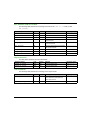
Reflex Digital Output Characteristics
The table below describes SSI module BMX EAE 0300 reflex digital output characteristics:
Number of outputs channels
One 24 Vdc 0.5 A per SSI channel, three
channels per module
Output Voltage
19.2...30 Vdc (depends on field supply)
Output Type
Maximum Load Current
Push-pull
Each Point
0.5 A
Per Module
1.5 A
Leakage / point
-0.3 mA maximum (OFF)
On State Output Voltage Drop
1.35 Vdc maximum (0.5 A)
Maximum Load Capacitance
50 μF
Maximum Load Inductance
L = load inductance (Henry)
I = load current (A)
F = switching frequency (Hz)
0.5 Henry at 4 Hz switch frequency
L = 0.5 / (I² x F)
Maximum Physical Response Time
< 20 µs (Resistive load)
Response Time for Comparison
<= 1ms
Short Circuit
All channels are protected against short circuit
and over temperature
Fallback States
(Output Channels)
By default
Pre-defined fallback values on all channels
User Configurable
Setting
Hold last value
Pre-defined Values
(Output Fallback)
By default
Channels set to 0
User Configurable
Setting
Each channel configurable for 1 or 0
Polarity On Individual Output Channels
By default
Logic normal on all channels
User Configurable
Setting
Logic reverse on one or all channels
EIO0000000940 10/2014
Pre-defined fallback value on one or all channels
Logic normal on one or all channels
35
Inputs/Outputs Specifications
WARNING
OUTPUT SHORT-CIRCUIT OR OVERLOAD
Do not apply a high voltage (24 Vdc) to an output port when it is at "0" because there is no internal
short circuit protection.
Failure to follow these instructions can result in death, serious injury, or equipment
damage.
NOTE:
If the short circuit occurs on any channel, the power supply goes into the following mode:
Firstly the power supply cycles on as the hiccup mode, the peak current is less than 10 A with
about a 2 µs duration.
Then all channels are turned off after about 100 ms
36
EIO0000000940 10/2014
Inputs/Outputs Specifications
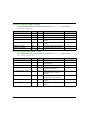
Programmable Input Filtering
Overivew
Each of the SSI module BMX EAE 0300 inputs allows input filtering. There are four levels of
filtering available (low, medium, high and without), that can be configured in the configuration
screen, as shown:
EIO0000000940 10/2014
37
Inputs/Outputs Specifications
Description
The filtering used is a programmable bounce filter, which operates as follows:
Bounce rejection diagram
In bounce rejection mode, the system delays all transitions until the signal remains stable for the
duration defined for the filter level.
Bounce rejection levels:
Input
CAP_IN0,1
38
Filter Level
Min Pulse
Max Frequency
Without
20 μs
200 Hz
Low (For Bounces > 2 kHz)
500 μs
200 Hz
Medium (For Bounces > 1 kHz)
1.25 ms
200 Hz
High (For Bounces > 250 Hz)
4.2 ms
100 Hz
EIO0000000940 10/2014
Modicon M340 with Unity Pro
SSI Module BMX EAE 0300 Functionalities
EIO0000000940 10/2014
Part II
SSI Module BMX EAE 0300 Functionalities
SSI Module BMX EAE 0300 Functionalities
Subject of this Part
This part presents the functionalities of the SSI module BMX EAE 0300.
What Is in This Part?
This part contains the following chapters:
Chapter
Chapter Name
Page
4
Configuration parameters
41
5
SSI Module BMX EAE 0300 Functions
43
6
Adjustment
59
7
Debugging the SSI Module BMX EAE 0300
61
8
Diagnostic of the SSI Module BMX EAE 0300
63
9
The Language Objects of the SSI Function
65
EIO0000000940 10/2014
39
SSI Module BMX EAE 0300 Functionalities
40
EIO0000000940 10/2014
Modicon M340 with Unity Pro
Configuration parameters
EIO0000000940 10/2014
Chapter 4
Configuration parameters
Configuration parameters
Configuration Screen for the SSI Module BMX EAE 0300
At a Glance
This section presents the configuration screen for the SSI module BMX EAE 0300.
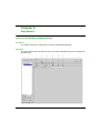
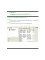
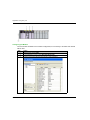
Illustration
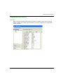
The figure below presents the configuration screen for the SSI module BMX EAE 0300:
EIO0000000940 10/2014
41
Configuration parameters
Description of the Screen
The following table presents the various parts of the above screen:
Number
Column
Function
1
Tab
The tab in the foreground indicates the current mode. The current mode is the
configuration mode in this example.
2
Label
These fields contain the name of each variable that may be configured. They may
not be modified.
3
Symbol
These fields contain the address of the variable in the application. They may not
be modified.
4
Value
If these fields have a downward pointing arrow, you can select the value of each
variable from various possible values in these fields. The various values can be
accessed by clicking on the arrow. A drop-down menu containing all the possible
values is displayed and the user may then select the required value of the variable.
5
Unit
These fields contain the unit of each variable that may be configured. They may
not be modified.
NOTE: Refer to the desired function (see page 43) in order to properly configure the SSI module
BMX EAE 0300.
42
EIO0000000940 10/2014
Modicon M340 with Unity Pro
SSI Module BMX EAE 0300 Functions
EIO0000000940 10/2014
Chapter 5
SSI Module BMX EAE 0300 Functions
SSI Module BMX EAE 0300 Functions
Overview
This chapter deals with functions of the SSI module BMX EAE 0300.
What Is in This Chapter?
This chapter contains the following topics:
Topic
Page
SSI Interface
44
Modulo and Reduction Functions
45
Offset Function
46
Inverted SSI Direction Function
47
Multiple Application of Reformatting
48
Capture Function
49
Compare Function
51
SSI Status Register
54
Event Sent To Application
55
Output Block Functions
56
EIO0000000940 10/2014
43
SSI Module BMX EAE 0300 Functions
SSI Interface
Description of the SSI Interface
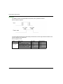
The figure below represents a SSI frame:
NOTE: This module does not control the turn value. For multi-turn encoders, the angle and turn
values constitute a single and unique value for the module.
The following are the other main characteristics of the frame and the interface:
Parameters
Values or observations
Code
Binary or Gray
SSI transmission baud rate
100 kHz, 200 kHz, 500 kHz or 1 MHz
Data bits
8 to 31 bits (MSB transferred first)
Status bits
0 to 1 bit (error bit may be handled by firmware)
Parity
Even, Odd or Without parity
Reloading Time
10 to 40 µs depending on encoder
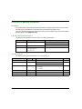
Parameter Details
There are four choices for the baud rate parameter which impact the maximum cable length:
Baud rate
100 kHz
Maximum cable length 350 m
200 kHz
500 kHz
1 MHz
180 m
70 m
20 m
The data bits parameter enables the number of data bits supplied by the encoder to be declared
(from MSB to LSB). The upper limit is 31.
The Status bit is the status flag which is refreshed when receiving this bit in the sequence. For
some encorders, this bit can indicate the detected error in the data frame.
The Parity parameter enables a Parity bit to be declared in the frame. If the parity bit is selected,
the modules carry out the parity check according to the choice of parity type, even or odd.
After the last rising edge of the clock signal, the Reloading time defines how long it takes until the
rotary encoder can be selected for the next transmission. This reloading time is determined by the
period of SSI pulse train. The reading cycle of SSI module is fixed by 1 ms.
44
EIO0000000940 10/2014
SSI Module BMX EAE 0300 Functions
Modulo and Reduction Functions
Description
The two functions are:
Modulo: the modulo function limits the dynamics of the position value to within a number of
points defined by the value of the parameter. An event (if enabled) detects the modulo (positive
or negative) passing.
Reduction: the function reduces the intrinsic resolution of the encoder by a value defined by the
"reduction" parameter. This reduction is carried out by a shift in the bits field provided by the
encoder.
The two parameters are of a "constant configuration" (%K) type.
Details for Modulo and Reduction
The modulo and reduction value is expressed as the exponent of 2.
The number of modulo bits is limited from 8 to 31 while the number of reduction bits is limited
from 0 to 7 bit.
When the reflex output is asserted ("1") by the presence of modulo value passing, it will keep
the value "1" until a rising edge of an extra clear bit of %Q occurs.
The modulo passing detection is only available when module < data width.
For example: if the data width is 13-bit, then the modulo passing will not be detected when the
modulo is from 13 to 31. (The default value of modulo is 31.)
EIO0000000940 10/2014
45
SSI Module BMX EAE 0300 Functions
Offset Function
Description
NOTE: The Encoder offset parameters are set in the Adjust tab.
Encoder offset: the user enters the absolute encoder offset parameter. The correction function
of the encoder offset systematically corrects the offset produced by the encoder on mechanical
position "0". This value is set in an adjustment word (%MW).
46
EIO0000000940 10/2014
SSI Module BMX EAE 0300 Functions
Inverted SSI Direction Function
Description
If the direction of input SSI data is inverted by the configuration, the output data is transferred by
the following equation:
Inverted_value = 2N - Original_value
N: encoder data width.
NOTE: Inverted_0 = 0.
EIO0000000940 10/2014
47
SSI Module BMX EAE 0300 Functions
Multiple Application of Reformatting
Description
In case the user applies all the reformatting function at the same time, it is necessary to define the
priority of them: Invert > Reduction > Offset > Modulo.
Example
With the following conditions:
Data_width = 11 bits
Modulo = 256 (8 bits)
Reduction = 1 bit
Enter the offset value after reduction.
In this example, because the full range resolution becomes 211-1 after reduction, to have a physical
offset of half range, the offset value should be set as:
Offset = 512
After the offset value has been added, if the reformatted value exceeds 211-1, then the value will
be masked by 211-1.
If the original data is 00001001001 in binary (73 in decimal), while SSI direction is inverted:
Invert [73] = 211 - 73 = 1975
Reduct [1975] = 1975 / 21 = 987
Offset [987] = 987 + 512 - 211-1 = 475
Mod [475/256] = 219
The final result in %IW is 219. As to the Gray code, it will be converted by XCEL automatically. The
original data in SSI register is always in binary.
48
EIO0000000940 10/2014
SSI Module BMX EAE 0300 Functions
Capture Function
Description
Capture is used to copy the current value of the SSI register to a capture register. It fixes the
immediate value at the precise moment the operation started.
The SSI module has two capture inputs, CAP_IN0 and CAP_IN1 respectively.
The Capture done information is an event which can undergo an event processing operation.
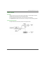
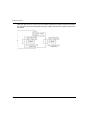
Function Hardware Structure
The figure below shows the hardware structure of the capture function:
EIO0000000940 10/2014
49
SSI Module BMX EAE 0300 Functions
Operation
The trend diagram below shows the capture mode on the rising edge of CAP_IN:
The other mode (capture on falling edge) is similar.
Details of Capture Function
The operation is triggered by the hardware when a CAP_IN physical input status is changed
when the capture enabling command is enabled. The SSi module capture modes are:
Capture on rising edge of an CAP_IN input.
The capture value is recorded in the Capture Register 0 for CAP_IN0, and in the Capture
Register 1 for CAP_IN1.
Capture on falling edge of an CAP_IN input.
The capture value is recorded in the Capture Register 0 for CAP_IN0, and in Capture
Register 1 for CAP_IN1.
If the Modulo (see page 45), Reduction (see page 45), Offset (see page 46) and SSI direction
(see page 47) functions have been applied, the captured value is affected as well.
The current value of SSI register must be valid before the event. If the Validity bit is false (low)
the capture is not performed.
The three SSI channels share the common capture inputs of CAP_IN0 and CAP_IN1. The
capture action of unwanted channel(s) can be disabled by the validate bit.
Example Capture on Rising or Falling Edge
The capture mode on the rising or falling edge of a physical input can be used to monitor the
progress of the manufacture of a part. This means that the position of the encoder can be captured
when part enters.
50
EIO0000000940 10/2014
SSI Module BMX EAE 0300 Functions
Compare Function
Description
The comparison function allows triggering event tasks or a reflex output according to the current
value in comparison to a threshold. The SSI module has two comparators. The comparison is
made in both directions (upper threshold and lower threshold).
Example with Compare
These comparators can be used to warn that a position has been exceeded. As soon as the current
value reaches the threshold, the event task associated with the module is called and can activate
an alarm to inform you of the end of a maneuver.
Comparison Thresholds
The comparison block has two thresholds:
The upper threshold: upper_th_value double word (%QDr.m.c.6)
The lower threshold: lower_th_value double word (%QDr.m.c.4)
The upper threshold value must be greater than or equal to the lower threshold value.
If the upper threshold is less than the lower threshold, the threshold error bit (%IWr.m.c.1 x9) is
asserted and all the compare functions of this channel are disabled.
The default value of upper_th_value and lower_th_value is 0.
WARNING
UNEXPECTED REFLEX OUTPUT BEHAVIOR
Set right value in upper_th_value and lower_th_value before activating the compare
enable bit.
Failure to follow these instructions can result in death, serious injury, or equipment
damage.
Comparison Status Register
The results of comparison are stored in the output word named compare_status register.
The two thresholds may be compared with the:
current value of SSI register
value of capture register 0
value of capture register 1
NOTE: The compare results for all the three modes can only be handled by a firmware interrupt,
the delay of the reaction depends on the interrupt priority and the system response time (for
example, 1 ms).
EIO0000000940 10/2014
51
SSI Module BMX EAE 0300 Functions
The possible results are:
Low: The value is less than the lower threshold value.
Window: The value is between the upper and lower thresholds or equal to one of the two
thresholds.
High: The value is greater than the upper threshold.
The compare_status register (%IWr.m.c.1) consists of:
Status
register bit
15
Compared
element
Comparison
result
14
13 12 11 10
9
8
7
6
5
Capture 1
High Window Low
4
3
Capture 0
2
1
0
SSI Register
High Window Low High Window Low
Register Updates
When the validate bit is False (Low), the compare status register is cleared.
Update Time:
The comparison with capture 0 and capture 1 registers values is performed every time the
registers are loaded.
The comparison with the SSI register occurs for each refreshed value (each 1 ms).
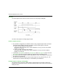
Modification of the Thresholds during the Operational Phase
If the application needs to modify the thresholds during the running of the SSI input, the Compare
Suspend Bit holds the Compare Status Register during the modification of threshold.
Compare Status Register needs the Compare Enable Bit set active (1) and Compare Suspend
Bit set inactive (0) to be updated. Both Compare Enable Bit and Compare Suspend Bit are set
through the Output Word.
52
EIO0000000940 10/2014
SSI Module BMX EAE 0300 Functions
The following figure illustrates the actions of the compare_enable bit (%QWr.m.c.0.5) and the
compare_suspend bit (%QWr.m.c.0.6):
When Compare Enable Bit is False, the compare status register is cleared.
When Compare Suspend Bit is true, the compare status register holds the previous result of
comparison until this bit becomes "0" again.
The threshold is updated if the channel gets the falling edge of the Compare Suspend Bit. For
example: at the moment that the Compare Suspend Bit turns from 1 to 0, the SSI module update
the threshold with the newest value in %QW.
NOTE: The user must enter the thresholds which are reformatting (modulo, reduction, offset and
direction reversed) if any reformatting function is applied.
EIO0000000940 10/2014
53
SSI Module BMX EAE 0300 Functions
SSI Status Register
Modulo Bit
This bit is used to detect the passing of modulo. It is set (active 1) when the SSI encoder value
passes the modulo, and it does not return to 0 unless the application clears (reset) the flag by using
the output command bit: Reset_Modulo_Flag.
Capture Event Bit
This bit is used to report the occurrence of a capture action. "1" indicates that there was a capture
action, "0" means no capture occurred so far. Once it is set, this bit stays at "1" until it is cleared by
the application by output command bit of Reset_Capture_Flag.
Frame Error Bit
This bit reports any detected error during the sequence. The Line_err bit is also reported via this
bit. The detected line error, such as the drop of line, changes the status of Frame Error bit to "1".
NOTE: The BMX EAE 0300 module asserts a frame error (line drop) by seeing an all "1" frame
(internally pull-up). This means in case the real input position is just an all "1" frame, the frame error
bit will also be set and the current value (all "1") will not be updated to the SSI register. The position
value will be updated once the encoder leaves the all "1" position.
NOTE: The user is suggested to walk around the all "1" position by using the multi-turn encoder or
set the appropriate modulo / reduction parameter.
NOTE: The Frame Error bit can also detect a wrong configuration of SSI data width. But this
detection function depends on the SSI encoders. Some encoders support this function, while
others do not fully support it.
Status Bit
This bit provided by the encoder, which follows the LSB in the sequence is usually used to indicate
a detected error from the encoder.
NOTE: If the status bit is supported by the encoder, you should use it to detect when a wrong frame
has been sent.
Parity Bit
This bit indicates a parity error. "1" means the occurrence of detected error.
NOTE: If the parity bit is supported by the encoder, you should use it to detect when the frame has
been corrupted during transfer.
54
EIO0000000940 10/2014
SSI Module BMX EAE 0300 Functions
Event Sent To Application
Summary
The number of the event task must be declared in the module configuration screen.
The M340 SSI module includes 6 sources of events:
Source Name
Comment
Modulo
Event when the SSI value passed modulo
SSI Low
Event when the SSI value is lower than the lower
threshold
SSI Window
Event when the SSI value is within [lower threshold,
upper threshold]
SSI High
Event when the SSI value is greater than the upper
threshold
Capture 0
Event when capture register 0 updates
Capture 1
Event when capture register 1 updates
All the events sent by the module, regardless of the source, call the same single event task in the
PLC.
There is normally only one type of event signaled per call. The source producing the call is
determined in the event task via the Events Source variable. This variable is updated at the
beginning of event task processing.
NOTE: If two or more event sources occur in the same 1 ms cycle, then multiple events will be sent
(one event for one source).
Event Validate Description
When an action comes from an external event, this action must be validated before affecting the
application. There is one (Function)_Validation bit by function which can be impacted by an
external event.
Example Using Capture CAP_IN
This function holds the current SSI value in the Capture 0 register.
Valid_Capture0: When it is asserted as "1", it allows loading the current SSI value into the
Capture 0 register consequential to the CAP_IN0 (see page 50). When it is "0", the value in the
capture register 0 will not change.
Valid_Capture1: When it is asserted as "1", it allows loading the current SSI value into the
Capture 1 register consequential to the CAP_IN1 (see page 50). When it is "0", the value in the
capture register 1 will not change.
NOTE: In order to make a capture happen, besides the validate bit, the corresponding
configuration (%K) must be set also.
EIO0000000940 10/2014
55
SSI Module BMX EAE 0300 Functions
Output Block Functions
Overview
Every channel in the SSI module has one programmable output block that operates with the
Compare Status Register and affects the behavior of physical outputs Qx for each channel.
There are two ways to control the output:
From the application: the output corresponds to the status of the output bit from the output
command bit.
From the output function block: the user must enable the output block function. Then, the output
corresponds to the status of the output bit from the function block.
The following figure shows the output function block Q0:
Configurable Functions
The operational Latch Mode must be chosen among 11 functions in configuration tab.
As stated, the output comes:
Directly, from the application software (Normal Output): 1 function.
From the output function block (Reflex Output): 10 functions.
The output matches the state of the output bit in the output function block result.
The table below shows the configurable functions:
56
Function code
Programming
0
No reflex action (default)
1
SSI value low
The output is high if the SSI value is less than the lower threshold.
2
SSI value in a window
The output is high if the SSI value is between the upper and lower
thresholds or equal to one of the two thresholds.
EIO0000000940 10/2014
SSI Module BMX EAE 0300 Functions
Function code
Programming
3
SSI value high
The output is high if the SSI value is greater than the upper threshold.
4
Capture 0 low
The output is high if the capture 0 value is less than the lower threshold.
5
Capture 0 in a window
The output is high if the capture 0 value is between the upper and lower
thresholds or equal to one of the two thresholds.
6
Capture 0 high
The output is high if the capture 0 value is greater than the upper threshold.
7
Capture 1 low
The output is high if the capture 1 value is less than the lower threshold.
8
Capture 1 in a window
The output is high if the capture 1 value is between the upper and lower
thresholds or equal to one of the two thresholds.
9
Capture 1 high
The output is high if the capture 1 value is greater than the upper threshold.
10
Modulo Passing
The output is high if the SSI encoder value changes from lower to upper
than the modulo or from upper to lower direction.
Output Properties
The SSI module BMX EAE 0300 enables output signals to be adapted with three 24 Vdc field
actuators.
It is possible to configure the following parameters for each output:
Logic normal or logic reverse output polarity for each channel on the module
Fallback mode and state for every module channel
Detected Error Recovery
Outputs Q0, Q1 and Q2 are current limited (0.5 A maximum).
A thermal shutdown protects each output.
When a short-circuit is detected on one of the output channels, the SSI module latches off the
output channel.
If an output channel has been latched off because of short-circuit detection, the SSI module
recovers from the short-circuit after the following sequence is processed:
The short-circuit has been corrected
To reset the detected error, the application must:
Reset the output_block_enable bit if it is active
Command the ouput to 0 Vdc (depends on the polarity).
NOTE: A minimum delay of 10 s occurs before the detected error is cleared.
EIO0000000940 10/2014
57
SSI Module BMX EAE 0300 Functions
Output Polarity Programming
By default, the polarity on all output channels is logic normal, where:
0 indicates that the physical actuator is off (the output signal is low)
1 indicates that the physical actuator is on (the output signal is high)
It is possible to configure the polarity parameter for each output during the channel
configuration to "1" or "0".
Output Fallback Modes
The fallback modes are the predefined states to which the output channels revert when the channel
is not controlled by the processor (for example, when communications are lost or when the
processor is stopped).
The fallback mode of each output channel can be configured as one of the following modes:
Predefined state: you may configure the fallback value as 0 or 1
Hold last value: the output block function continues to operate according to the last
received commands.
NOTE: By default, the fallback mode of the 3 output channels is Predefined state; the
fallback value parameter is 0.
58
EIO0000000940 10/2014
Modicon M340 with Unity Pro
Adjustment
EIO0000000940 10/2014
Chapter 6
Adjustment
Adjustment
Screen for the SSI Module BMX EAE 0300
At a Glance
This chapter presents the adjust screen for the SSI module BMX EAE 0300.
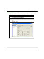
Illustration
The figure below presents the Adjust screen for the SSI module BMX EAE 0300 in absolute SSI
encoder mode:
EIO0000000940 10/2014
59
Adjustment
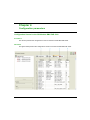
Description of the Screen
The following table presents the various parts of the above screen:
Number
Column
Function
1
Label
These fields contain the name of each variable that may be adjusted. They may
not be modified and can be accessed in both local and online modes.
2
Tab
The tab in the foreground indicates the current mode. The current mode is
therefore the adjust mode in this example.
3
Symbol
These fields contain the mnemonic name of the variable. They may not be modified
and can be accessed in both offline and online modes.
4
Initial value
These fields display the value of the variable that the user has adjusted in offline
mode. They are only accessible in online mode.
5
Value
The function of these fields depends on the mode in which the user is working:
In offline mode: these field are used to adjust the variable.
In online mode: these field are used to display the current value of the variable.
6
Unit
These fields contain the unit of each variable that may be configured. They may
not be modified and can be accessed in both offline and online modes.
60
EIO0000000940 10/2014
Modicon M340 with Unity Pro
Debugging the SSI Module
EIO0000000940 10/2014
Chapter 7
Debugging the SSI Module BMX EAE 0300
Debugging the SSI Module BMX EAE 0300
Debug Screen for the SSI Module BMX EAE 0300
At a Glance
This chapter presents the debug screen for the SSI module BMX EAE 0300. The Debug screen
can only be accessed in online mode.
Illustration
The screen presents the debug screen for the SSI module BMX EAE 0300:
EIO0000000940 10/2014
61
Debugging the SSI Module
Description of the Screen
The following table presents the various parts of the Debug screen:
Number
Column
Function
1
Reference
These fields contain the address of the variable in the application. They may not
be modified.
2
Label
These fields contain the name of each variable that may be configured. They may
not be modified.
3
Tab
The tab in the foreground indicates the current mode. The current mode is the
debug mode in this example.
4
Symbol
These fields contain the mnemonic name of the variable. They may not be
modified.
5
Value
If the fields have a downward pointing arrow, you can select the value of each
variable from various possible values in these fields. The various values can be
accessed by clicking on the arrow. A drop-down menu containing all the possible
values is displayed and the user may then select the required value of the variable.
If there is no downward pointing arrow, these fields simply display the current value
of the variable.
62
EIO0000000940 10/2014
Modicon M340 with Unity Pro
Diagnostic of the SSI Module BMX EAE 0300
EIO0000000940 10/2014
Chapter 8
Diagnostic of the SSI Module BMX EAE 0300
Diagnostic of the SSI Module BMX EAE 0300
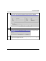
Diagnostic Screen for the SSI Module BMX EAE 0300
At a Glance
This chapter presents the fault display screen for the SSI module BMX EAE 0300. A fault display
screen of module may only be accessed in online mode.
Illustration
The figure below presents the Diagnostic Screen for the SSI module BMX EAE 0300 in position
control mode.
EIO0000000940 10/2014
63
Diagnostic of the SSI Module BMX EAE 0300
Description of the Screen
The following table presents the various parts of the Diagnostic screen:
Number
Column
Function
1
Internal faults
These fields display the module’s active detected internal errors.
2
Tab
This tab in the foreground indicates the current mode. The current mode is the
Fault display mode in this example.
3
External faults
These fields display the module’s active detected external errors.
4
Other faults
These fields display the module’s active detected errors, other than internal
and detected external errors.
Description of the Fault Type
The following table presents the list of detected error types:
64
Number
Fault type
Name
Display
0
External
EXT0_FLT
External Fault on Inputs
1
External
EXT1_FLT
External Fault on Outputs
2
Internal
INTERNAL_FLT
Faulty channel
3
Internal
CONF_FLT
Detected hardware or software
configuration fault
4
Internal
COM_FLT
Module missing or off (interruption of
communication with PLC)
5
Internal
APPLI_FLT
Application mistake (configuration or
adjustment)
6
External
Field Supply
Field supply low voltage
7
External
S_Circuit OUT
Reflex Output (24 Vdc) inoperative
after Short Circuit
EIO0000000940 10/2014
Modicon M340 with Unity Pro
EIO0000000940 10/2014
Chapter 9
The Language Objects of the SSI Function
The Language Objects of the SSI Function
Overview
This chapter describes the language objects associated to the SSI module BMX EAE 0300 tasks
as well as the different ways of using them.
What Is in This Chapter?
This chapter contains the following sections:
Section
Topic
Page
9.1
The Language Objects and IODDT of the SSI Function
66
9.2
Language Objects and IODDTs Associated with the SSI Function
75
9.3
The IODDT Type T_GEN_MOD Applicable to All Modules
81
9.4
Language Objects and Device DDT Associated with the SSI Function
83
EIO0000000940 10/2014
65
Section 9.1
The Language Objects and IODDT of the SSI Function
The Language Objects and IODDT of the SSI Function
At a Glance
This section presents an overview of the position control IODDT languages and objects.
What Is in This Section?
This section contains the following topics:
Topic
66
Page
Introducing Language Objects for Application-Specific SSI
67
Implicit Exchange Language Objects Associated with the Application-Specific Function
68
Explicit Exchange Language Objects Associated with the Application-Specific Functions
69
Management of Exchanges and Reports with Explicit Objects
71
EIO0000000940 10/2014
Introducing Language Objects for Application-Specific SSI
Language Object Types
There are two types of language objects:
Implicit Exchange Objects: these objects are automatically exchanged on each cycle
revolution of the task associated with the module
Implicit exchanges concern the inputs/outputs of the module (measurement results, information
and commands). These exchanges enable the debugging of the counting modules.
Explicit Exchange Objects: these objects are exchanged on the application’s request, using
explicit exchange instructions
Explicit exchanges enable the module to be set and diagnosed.
EIO0000000940 10/2014
67
Implicit Exchange Language Objects Associated with the Application-Specific
Function
At a Glance
An integrated application-specific interface or the addition of a module automatically enhances the
language objects application used to program this interface or module.
These objects correspond to the input/output images and software data of the module or integrated
application-specific interface.
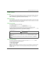
Module Inputs
The module inputs (%I and %IW) are updated in the PLC memory at the start of the task, the PLC
being in RUN or STOP mode.
The outputs (%Q and %QW) are updated at the end of the task, only when the PLC is in RUN mode.
NOTE:
When the task occurs in STOP mode, either of the following are possible, depending on the
configuration selected:
outputs are set to fallback position (fallback mode)
outputs are maintained at their last value (maintain mode)
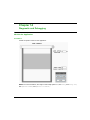
Operating Cycle of a PLC Task
The following diagram shows the cyclical execution of a PLC task.
68
EIO0000000940 10/2014
Explicit Exchange Language Objects Associated with the Application-Specific
Functions
Introduction
Explicit exchanges are performed at the user program’s request using these instructions:
READ_STS (see Unity Pro, I/O Management, Block Library) (read status words)
WRITE_PARAM (see Unity Pro, I/O Management, Block Library) (write adjustment parameters)
READ_PARAM (see Unity Pro, I/O Management, Block Library) (read adjustment parameters)
SAVE_PARAM (see Unity Pro, I/O Management, Block Library) (save adjustment parameters)
RESTORE_PARAM (see Unity Pro, I/O Management, Block Library) (restore adjustment
parameters)
These exchanges apply to a set of %MW objects of the same type (status, commands or
parameters) that belong to a channel.
NOTE:
These objects can:
provide information about the module (for example, type of channel detected error)
define the module’s operating modes (save and restore adjustment parameters in the process
of application)
NOTE: In order to avoid several simultaneous explicit exchanges for the same channel, it is
necessary to test the value of the word EXCH_STS (%MWr.m.c.0) of the IODDT associated to the
channel before calling any EF addressing this channel.
EIO0000000940 10/2014
69
General Principle for Using Explicit Instructions
The diagram below shows the different types of explicit exchanges that can be made between the
application and module:
Managing Exchanges
During an explicit exchange, it is necessary to check performance to ensure data is only taken into
account when the exchange has been correctly executed.
To do this, two types of information is available:
information concerning the exchange in progress (see Unity Pro, I/O Management, Block
Library)
the exchange report (see Unity Pro, I/O Management, Block Library)
The following diagram describes the management principle for an exchange:
NOTE: In order to avoid several simultaneous explicit exchanges for the same channel, it is
necessary to test the value of the word EXCH_STS (%MWr.m.c.0) of the IODDT associated to the
channel before calling any EF addressing this channel.
70
EIO0000000940 10/2014
Management of Exchanges and Reports with Explicit Objects
At a Glance
When data is exchanged between the PLC memory and the module, the module may require
several task cycles to acknowledge this information. All IODDTs use two words to manage
exchanges:
EXCH_STS (%MWr.m.c.0): exchange in progress
EXCH_RPT (%MWr.m.c.1): report
NOTE:
Depending on the localization of the module, the management of the explicit exchanges (for
example, %MW0.0.MOD.0.0) are not detected by the application:
For in-rack modules, explicit exchanges are done immediately on the local PLC bus and are
finished before the end of the execution task. The READ_STS, for example, is always finished
when the %MW0.0.mod.0.0 bit is checked by the application.
For remote bus (Fipio for example), explicit exchanges are not synchronous with the execution
task, so the detection is possible by the application.
Bits for Managing Exchanges
The illustration below shows the different significant bits for managing exchanges:
EIO0000000940 10/2014
71
Description of Significant Bits
Each bit of the words EXCH_STS (%MWr.m.c.0) and EXCH_RPT (%MWr.m.c.1) is associated with
a type of parameter:
Rank 0 bits are associated with the status parameters:
The STS_IN_PROGR bit (%MWr.m.c.0.0) indicates whether a read request for the status
words is in progress.
The STS_ERR bit (%MWr.m.c.1.0) specifies whether a read request for the status words is
accepted by the module channel.
Rank 2 bits are associated with the adjustment parameters:
The ADJ_IN_PROGR bit (%MWr.m.c.0.2) indicates whether the adjustment parameters are
being exchanged with the module channel (via WRITE_PARAM, READ_PARAM, SAVE_PARAM
or RESTORE_PARAM).
The ADJ_ERR bit (%MWr.m.c.1.2) specifies whether the adjustment parameters are
accepted by the module. If the exchange is correctly executed, the bit is set to 0.
Rank 15 bits indicate a reconfiguration on channel c of the module from the console
(modification of the configuration parameters + cold start-up of the channel).
NOTE: r represents the rack number, m the position of the module in the rack, while c represents
the channel number in the module.
NOTE: Exchange and report words also exist at module level EXCH_STS (%MWr.m.MOD) and
EXCH_RPT (%MWr.m.MOD.1) as per IODDT type T_GEN_MOD.
Data Exchange Example
Phase 1: Sending data by using the WRITE_PARAM instruction
When the instruction is scanned by the PLC processor, the Exchange in progress bit is set to 1
in %MWr.m.c.
Phase 2: Analysis of the data by the I/O module.
When the data is exchanged between the PLC memory and the module, acknowledgement by the
module is managed by the ADJ_ERR bit (%MWr.m.c.1.2).
72
EIO0000000940 10/2014
This bit’s values are:
0: correct exchange
1: detected error in the exchange
NOTE: There is no adjustment parameter at module level.
Execution Indicators for an Explicit Exchange: EXCH_STS
The table below shows the control bits of the explicit exchanges: EXCH_STS (%MWr.m.c.0)
Standard symbol
Type
Access
Meaning
STS_IN_PROGR
BIT
R
Reading of channel status words in progress %MWr.m.c.0.0
Address
Unused
BIT
R
Unused
%MWr.m.c.0.1
ADJUST_IN_PROGR
BIT
R
Adjust parameters exchange in progress
%MWr.m.c.0.2
RECONF_IN_PROGR
BIT
R
Reconfiguration of the module in progress
%MWr.m.c.0.15
NOTE: If the module is not present or is disconnected, explicit exchange objects (READ_STS for
example) are not sent to the module (STS_IN_PROG (%MWr.m.c.0.0) = 0), but the words are
refreshed.
Explicit Exchange Report: EXCH_RPT
The table below shows the report bits: EXCH_RPT (%MWr.m.c.1)
Standard symbol
Type
Access
Meaning
Address
STS_ERR
BIT
R
Detected error reading channel status words
(1 = reading not done)
%MWr.m.c.1.0
%MWr.m.c.1.1
Unused
BIT
R
Unused
ADJUST_ERR
BIT
R
Detected error during an adjust parameter exchange %MWr.m.c.1.2
(1 = exchange not done)
RECONF_ERR
BIT
R
Error during reconfiguration of the channel
(1 = reconfiguration not done)
EIO0000000940 10/2014
%MWr.m.c.1.15
73
SSI Module Use
The following table describes what happens between a SSI module and the system after a poweron:
Step
Action
1
Power on.
2
The system sends the configuration parameters.
3
The system sends the adjust parameters by WRITE_PARAM method.
Note: When the operation is finished, the bit %MWr.m.c.0.2 switches to 0.
If, in the begining of your application, you use a WRITE_PARAM command, you must wait until the
bit %MWr.m.c.0.2 switches to 0.
74
EIO0000000940 10/2014
Section 9.2
Language Objects and IODDTs Associated with the SSI Function
Language Objects and IODDTs Associated with the SSI
Function
At a Glance
An integrated application-specific interface or the addition of a module automatically enhances the
language objects application used to program this interface or module.
These objects correspond to the input/output images and software data of the module or integrated
application-specific interface.
What Is in This Section?
This section contains the following topics:
Topic
Page
General Information
76
Implicit Exchange Objects for the T_SSI_BMX IODDT
77
EIO0000000940 10/2014
75
General Information
General
The SSI modules have two associated IODDTs. These IODDTs are predefined by the
manufacturer and contains language objects for inputs/outputs belonging to the channel of an
application-specific module.
The IODDT associated with the SSI modules are:
language objects at Module Level of the SSI Module (T_GEN_MOD)
language objects associated with the SSI channel 0, 1 or 2 (T_SSI_BMX)
IODDT variables can be created in two different ways using the:
I/O objects (see page 101) tab
Data Editor (see page 106)
Each IODDT contains a set of language objects allowing its operation to be controlled and
checked.
76
EIO0000000940 10/2014
Implicit Exchange Objects for the T_SSI_BMX IODDT
At a Glance
The tables below present the T_SSI_BMX types IODDT implicit exchange objects which are
applicable to the SSI module BMX EAE 0300.
In general, the meaning of the bits is given for bit status 1.
Not all bits are used.
Counter Value and Sensor Values
The table below presents the current counting value and the captured values:
Standard symbol
Type
Access
Meaning
Language object
SSI_CURRENT_VALUE
DINT
R
Current value of SSI register
%IDr.m.c.2
CAPT_0_VALUE
DINT
R
Value latched into Capture register 0
%IDr.m.c.4
CAPT_1_VALUE
DINT
R
Value latched into Capture register 1
%IDr.m.c.6
%Ir.m.c bits
The table below presents the meanings of the %Ir.m.c bits:
Standard symbol
Type
Access
Meaning
Language object
ST_REFLEX_OUTPUT
EBOOL
R
Voltage level applied to the 24 Vdc
channel output
0: 0 Vdc
1: 24 Vdc
%Ir.m.c.0
ST_OUTPUT_LATCH
EBOOL
R
Logical state of internal channel Latch %Ir.m.c.1
ST_CAPT_INPUT_0
EBOOL
R
%Ir.m.c.2
ST_CAPT_INPUT_1
EBOOL
R
%Ir.m.c.3
SSI_Status, %IWr.m.c.0 Word
The following table presents the meanings of the bits of the %IWr.m.c.0 status word, named
SSI_STATUS:
Standard symbol
Type
Access
Meaning
Language object
Reserved
BIT
MODULO_FLAG
BIT
R
Reserved
%IWr.m.c.0.0
R
0: no modulo passing
1: modulo passing
%IWr.m.c.0.1
CAPT_0_FLAG
BIT
R
0: the capture 0 register is not updated %IWr.m.c.0.2
1: the capture 0 register is updated
NOTE: Flag set by capture 0 register
update (when event enabled.)
EIO0000000940 10/2014
77
Standard symbol
Type
Access
Meaning
Language object
CAPT_1_FLAG
BIT
R
0: the capture 1 register is not updated %IWr.m.c.0.3
1: the capture 1 register is updated
NOTE: Flag set by capture 1 register
update (when event enabled.)
SSI_FRAME_ERR_FLAG
BIT
R
0: the SSI frame is correct
%IWr.m.c.0.4
1: the line error such as the drop of line
exists
SSI_STATUS_ERR_FLAG
BIT
R
indicates a detected read data error
%IWr.m.c.0.5
SSI_PARITY_ERR_FLAG
BIT
R
0: parity correct
1: parity error
%IWr.m.c.0.6
COMPARE_STATUS, %IWr.m.c.1 Word
The following table presents the meanings of the bits of the %IWr.m.c.1 status word, named
COMPARE_STATUS:
Standard symbol
Type
Access
Meaning
Language object
SSI_LOW
BIT
R
Current SSI value less than lower threshold
(%QDr.m.c.4)
%IWr.m.c.1.0
SSI_WIN
BIT
R
Current SSI value is between lower threshold
(%QDr.m.c.4) and upper threshold
(%QDr.m.c.6)
%IWr.m.c.1.1
SSI_HIGH
BIT
R
Current SSI value greater than upper threshold
(%QDr.m.c.6)
%IWr.m.c.1.2
CAPT_0_LOW
BIT
R
Value captured in register 0 is less than lower
threshold (%QDr.m.c.4)
%IWr.m.c.1.3
CAPT_0_WIN
BIT
R
Value captured in register 0 is between lower
threshold (%QDr.m.c.4) and upper threshold
(%QDr.m.c.6)
%IWr.m.c.1.4
CAPT_0_HIGH
BIT
R
Value captured in register 0 is greater than upper
threshold (%QDr.m.c.6)
%IWr.m.c.1.5
CAPT_1_LOW
BIT
R
Value captured in register 1 is less than lower
threshold (%QDr.m.c.4)
%IWr.m.c.1.6
CAPT_1_WIN
BIT
R
Value captured in register 1 is between lower
threshold (%QDr.m.c.4) and upper threshold
(%QDr.m.c.6)
%IWr.m.c.1.7
CAPT_1_HIGH
BIT
R
Value captured in register 1 is greater than upper
threshold (%QDr.m.c.6)
%IWr.m.c.1.8
LT_HIGH
BIT
R
Lower threshold (%QDr.m.c.4) is greater than
upper threshold (%QDr.m.c.6)
%IWr.m.c.1.9
78
EIO0000000940 10/2014
EVT_SOURCES, %IWr.m.c.10 Word
The following table presents the meanings of the bits of the %IWr.m.c.10 word, named
EVT_SOURCES:
Standard symbol
Type
Access
Meaning
Language object
Reserved
BIT
R
Reserved
%IWr.m.c.10.0
EVT_MODULO
BIT
R
Event due to modulo switch
%IWr.m.c.10.1
Reserved
BIT
R
Reserved
%IWr.m.c.10.2
EVT_SSI_LOW
BIT
R
Event due to SSI value being less than %IWr.m.c.10.3
lower threshold
EVT_SSI_WINDOW
BIT
R
Event due to SSI value being between %IWr.m.c.10.4
the two thresholds
EVT_SSI_HIGH
BIT
R
Event due to SSI value being greater
than upper threshold
%IWr.m.c.10.5
EVT_CAPT_0
BIT
R
Event due to capture function 0
%IWr.m.c.10.6
EVT_CAPT_1
BIT
R
Event due to capture function 1
%IWr.m.c.10.7
EVT_OVERRUN
BIT
R
Events have been lost
%IWr.m.c.10.9
Output Thresholds
The table below presents the output thresholds:
Standard symbol
Type
Access
Meaning
Language object
LOWER_TH_VALUE
DINT
R/W
Lower threshold value
%QDr.m.c.4
UPPER_TH_VALUE
DINT
R/W
Upper threshold value
%QDr.m.c.6
%Qr.m.c.d Words
The following table presents the meanings of the output words:
Standard symbol
Type
Access
Meaning
Language object
OUTPUT_FORCE
EBOOL
R/W
1: the reflex output forced to "1".
0 and reflex block is disables: the
reflex output returns
%Qr.m.c.0
REFLEX_BLOCK_ENABLE
EBOOL
R/W
1: Output Block function enabled
%Qr.m.c.1
EIO0000000940 10/2014
79
FUNCTIONS_ENABLING, %QWr.m.c.0 Word
The following table presents the meanings of the bits of the %QWr.m.c.0 word, named
FUNCTIONS_ENABLING:
Standard symbol
Type
Access
Meaning
Language object
Reserved
BIT
R/W
Reserved
%QWr.m.c.0.0
Reserved
BIT
R/W
Reserved
%QWr.m.c.0.1
Reserved
BIT
R/W
Reserved
%QWr.m.c.0.2
VALID_CAPT_0
BIT
R/W
Capture authorization in the capture0
register
%QWr.m.c.0.3
VALID_CAPT_1
BIT
R/W
Capture authorization in the capture1
register
%QWr.m.c.0.4
COMPARE_ENABLE
BIT
R/W
Comparators operation authorization
%QWr.m.c.0.5
COMPARE_SUSPEND
BIT
R/W
Comparator frozen at its last value
%QWr.m.c.0.6
EVT_SOURCES_ENABLING, %QWr.m.c.1 Word
The following table presents the meanings of the bits of the %QWr.m.c.1 word, named
EVT_SOURCES_ENABLING:
Standard symbol
Type
Reserved
BIT
EVT_MODULO_ENABLE
BIT
Reserved
BIT
R/W
Reserved
EVT_SSI_LOW_ENABLE
BIT
R/W
EVENT task call when the SSI value is %QWr.m.c.1.3
less than lower threshold
EVT_SSI_WINDOW_ENABLE
BIT
R/W
EVENT task call when the SSI value is %QWr.m.c.1.4
between the lower and upper
threshold
EVT_SSI_HIGH_ENABLE
BIT
R/W
EVENT task call when the SSI value is %QWr.m.c.1.5
greater than the upper threshold
EVT_CAPT_0_ENABLE
BIT
R/W
EVENT task call during capture in
register 0
%QWr.m.c.1.6
EVT_CAPT_1_ENABLE
BIT
R/W
EVENT task call during capture in
register 1
%QWr.m.c.1.7
80
Access
Meaning
Language object
R/W
Reserved
%QWr.m.c.1.0
R/W
EVENT task called when there is a SSI %QWr.m.c.1.1
module passing
%QWr.m.c.1.2
EIO0000000940 10/2014
Section 9.3
The IODDT Type T_GEN_MOD Applicable to All Modules
The IODDT Type T_GEN_MOD Applicable to All Modules
Language Objects of the IODDT of Type T_GEN_MOD
Introduction
All the modules of Modicon M340 PLCs have an associated IODDT of type T_GEN_MOD.
In general, the meaning of the bits is given for bit status 1.
Not all bits are used.
List of Objects
The table below presents the objects of the IODDT at module level:.
Standard Symbol
Type
MOD_ADDRESS
MOD_ERROR
BOOL
Access
Meaning
Address
R
Language element of module level
used for READ_STS
%CHr.m.MOD
R
Detected module error bit
%Ir.m.MOD.ERR
%MWr.m.MOD.0
EXCH_STS
INT
R
Detected module exchange status
STS_IN_PROGR
BOOL
R
Reading of status words of the module %MWr.m.MOD.0.0
in progress
EXCH_RPT
INT
R
Exchange report word
%MWr.m.MOD.1
STS_ERR
BIT
R
Event when reading module status
words
%MWr.m.MOD.1.0
MOD_FLT
INT
R
Detected internal error word of the
module
%MWr.m.MOD.2
MOD_FAIL
BIT
R
Detected internal error, module
inoperable
%MWr.m.MOD.2.0
CH_FLT
BIT
R
Inoperative channel(s)
%MWr.m.MOD.2.1
BIT
R
Module in self-tests
%MWr.m.MOD.2.3
CONF_FLT
BIT
R
Detected hardware or software
configuration error
%MWr.m.MOD.2.5
NO_MOD
BIT
R
Module missing or inoperative
%MWr.m.MOD.2.6
EIO0000000940 10/2014
81
The table below presents the objects of the IODDT of channel:.
Standard Symbol
Type
CH_ADDRESS
CH_ERROR
82
BOOL
Access
Meaning
Address
R
Language element of channel level
used for explicit exchanges
READ_STS, READ_PARAM,
WRITE_PARAM, SAVE_PARAM and
RESTORE_PARAM
%CHr.m.c
R
Detected channel error bit
%Ir.m.c.ERR
EIO0000000940 10/2014
Section 9.4
Language Objects and Device DDT Associated with the SSI Function
Language Objects and Device DDT Associated with the
SSI Function
At a Glance
This section presents the device DDT of the module BMX EAE 0300 and the DDT used for the
variables in explicit exchanges.
What Is in This Section?
This section contains the following topics:
Topic
Page
Device DDT for BMX EAE 0300 Module
84
DDT Description for Explicit Exchange
88
EIO0000000940 10/2014
83
Device DDT for BMX EAE 0300 Module
Introduction
The Device DDT is a predefined DDT that describes the I/O language elements of the I/O module.
This data type is represented in a structure which provides bits and register view.
This topic describes the structure of the implicit Unity Pro Device DDT for the Synchronous Serial
Interface (SSI) module BMX EAE 0300.
T_M_SSI_3 Device DDT Description
The following table gives the structure of the T_M_SSI_3 Device DDT:
Name
Type
Description
MOD_HEALTH
BOOL
0 = the module has a detected error
1 = the module is operating correctly
MOD_FLT
EBOOL
internal detected errors of the module.
SSI_CH
ARRAY [0..2] of
T_M_SSI_STD_CH
(see page 84)
SSI channels
T_M_SSI_STD_CH
The following table gives the structure of T_M_SSI_STD_CH:
Name
Type
Description
Access
FCT_TYPE
WORD
Bit
Unused
read
CH_HEALTH
BOOL
0 = the channel has a detected error
read
1 = the channel is operating correctly
ST_REFLEX_OUTPUT
EBOOL
Voltage level applied to the 24 Vdc channel output:
0 = 0 Vdc
1 = 24 Vdc
read
ST_OUTPUT_LATCH
EBOOL
Logical state of internal channel Latch
read
ST_CAPT_INPUT_0
EBOOL
Physical input 0 state.
read
ST_CAPT_INPUT_1
EBOOL
Physical input 1 state.
read
84
EIO0000000940 10/2014
Name
Type
Bit
Description
Access
SSI_STATUS
INT
MODULO_FLAG
BOOL
1
Main status register.
Flag set by a modulo crossing event:
0 = no modulo passing
1 = modulo passing
read
CAPT_0_FLAG
BOOL
2
Flag set by capture 0 register update:
0 = the capture 0 register is not updated
1 = the capture 0 register is updated
NOTE: This parameter is not used because event
processing is not supported with device DDT.
CAPT_1_FLAG
BOOL
3
Flag set by capture 1 register update:
0 = the capture 1 register is not updated
1 = the capture 1 register is updated
NOTE: This parameter is not used because event
processing is not supported with device DDT.
SSI_FRAME_ERR_FLAG
BOOL
4
Flag set by a detected SSI frame error:
0 = the SSI frame is correct
1 = the line error such as the drop of line exists
SSI_STATUS_ERR_FLAG
BOOL
5
Flag set by a detected read data error.
SSI_PARITY_ERR_FLAG
BOOL
6
Flag set by a detected SSI parity error:
0 = parity is correct
1 = detected parity error
EIO0000000940 10/2014
85
Name
Type
Bit
Description
Access
Field of comparison result bits.
read
COMPARE_STATUS
INT
SSI_LOW
BOOL
0
Numeral current value is less than the lower threshold
(LOWER_TH_VALUE).
SSI_WIN
BOOL
1
Numeral current value is between lower threshold
(LOWER_TH_VALUE) and upper threshold
(UPPER_TH_VALUE).
SSI_HIGH
BOOL
2
Numeral current value is greater than the upper
threshold (UPPER_TH_VALUE).
CAPT_0_LOW
BOOL
3
Value captured in register 0 is less than lower
threshold.
CAPT_0_WIN
BOOL
4
Value captured in register 0 is between lower threshold
and upper threshold.
CAPT_0_HIGH
BOOL
5
Value captured in register 0 is greater than the upper
threshold.
CAPT_1_LOW
BOOL
6
Value captured in register 1 is less than lower
threshold.
CAPT_1_WIN
BOOL
7
Value captured in register 1 is between lower threshold
and upper threshold.
CAPT_1_HIGH
BOOL
8
Value captured in register 1 is greater than the upper
threshold.
LT_HIGH
BOOL
9
Lower threshold is greater than the upper threshold.
SSI_CURRENT_VALUE
UDINT
Main numerical current value of SSI register.
read
CAPT_0_VALUE
UDINT
Numerical current value latched into capture register 0. read
CAPT_1_VALUE
UDINT
Numerical current value latched into capture register 1. read
OUTPUT_FORCE
EBOOL
Force OUTPUT to logical active high state:
1 = the reflex output forced to 1.
0 and reflex block is disable = the reflex output
returns.
read/write
REFLEX_BLOCK_ENABLE
EBOOL
Enable the reflex block function:
1 = output block function enabled.
0 = output block function disabled.
read/write
FUNCTIONS_ENABLING
INT
Field of enable function bits.
read/write
VALID_CAPT_0
BOOL
3
Authorizes captures into the capture 0 register.
VALID_CAPT_1
BOOL
4
Authorizes captures into the capture 1 register.
COMPARE_ENABLE
BOOL
5
Authorizes comparators operation.
COMPARE_SUSPEND
BOOL
6
Hold comparator at latest result.
86
EIO0000000940 10/2014
Name
Type
Bit
Description
Access
SSI_STATUS_CLEAR
INT
MODULO_CLEAR
BOOL
1
Field of clear flag bits.
Clear the modulo flag of SSI.
read/write
CAPT_0_CLEAR
BOOL
2
Clear the capture 0 flag of SSI status.
CAPT_1_CLEAR
BOOL
3
Clear the capture 1 flag of SSI status.
SSI_FRAM_ERR_CLEAR
BOOL
4
Clear the SSI frame detected error flag.
SSI_STATUS_ERR_CLEAR BOOL
5
Clear the SSI status detected error flag.
SSI_PARITY_ERR_CLEAR
BOOL
6
Clear the SSI parity detected error flag.
LOWER_TH_VALUE
DINT
Value of the lower threshold.
read/write
UPPER_TH_VALUE
DINT
Value of the upper threshold.
read/write
EIO0000000940 10/2014
87
DDT Description for Explicit Exchange
Introduction
This section describes the DDT type used for the variables connected to dedicated EFB parameter
in an explicit exchange:
DDT Type
Explicit Exchange Function
EFB
Parameter
T_M_SSI_CH_STS
Read module/channel status
READ_STS_MX (see Unity
Pro, I/O Management, Block
Library)
STS
T_M_SSI_CH_PRM
Read parameter(1)
READ_PARAM_MX (see Unity PARAM
Pro, I/O Management, Block
Library)
Write parameter(1)
WRITE_PARAM_MX
(see Unity Pro, I/O
Management, Block Library)
Restore parameter(1)
RESTORE_PARAM_MX
Save parameter(1)
SAVE_PARAM_MX (see Unity
Pro, I/O Management, Block
Library)
(1) Parameter management is only possible for explicit exchange with I/O modules in M580 local rack.
NOTE: Targeted channel address (ADDR) can be managed with ADDMX (see Unity Pro, Communication,
Block Library) EF (connect the output parameter OUT to the input parameter ADDR of the communication
functions).
88
EIO0000000940 10/2014
T_M_SSI_CH_STS DDT Description
Name
Type
Bit
CH_FLT
INT
EXTERNAL_FLT_INPUTS
BOOL
0
Meaning
Access
Channel faults
read
Detected error on the inputs.
EXTERNAL_FLT_OUTPUTS
BOOL
1
Detected error on the outputs.
INTERNAL_FLT
BOOL
4
detected internal error, the channel
is inoperative.
CONF_FLT
BOOL
5
detected hardware or software
configuration error.
COM_FLT
BOOL
6
detected bus communication error.
APPLI_FLT
BOOL
7
detected error in application
(adjustment or configuration)
COM_EVT_FLT
BOOL
8
Communication detected error on
event.
OVR_EVT_CPU
BOOL
9
Overrun detected error on CPU
event.
OVR_CPT_CH
BOOL
10
Overrun detected error on channel
event.
CH_FLT_2
INT
SUPPLY_FLT
BOOL
2
detected field supply low voltage.
execution control flags
SHORT_CIRCUIT_OUT
BOOL
3
Short circuit on reflex output
(24 Vdc).
read
T_M_SSI_CH_PRM DDT Description
The following table shows the T_M_SSI_CH_PRM structure status word bits:
Name
Type
Bit
Meaning
Access
SSI_OFFSET
UDINT
–
Set the offset of the SSI value
read/write
EIO0000000940 10/2014
89
90
EIO0000000940 10/2014
Modicon M340 with Unity Pro
SSI Module BMX EAE 0300 Implementation Example
EIO0000000940 10/2014
Part III
Quick Start: SSI Module BMX EAE 0300 Implementation Example
Quick Start: SSI Module BMX EAE 0300 Implementation
Example
Overview
This part provides an example using the SSI module BMX EAE 0300.
What Is in This Part?
This part contains the following chapters:
Chapter
Chapter Name
Page
10
Example Overview
93
11
Hardware Installation
97
12
Configuring the SSI Module BMX EAE 0300 on Unity Pro
101
13
Programming the Example
105
14
Diagnostic and Debugging
111
EIO0000000940 10/2014
91
SSI Module BMX EAE 0300 Implementation Example
92
EIO0000000940 10/2014
Modicon M340 with Unity Pro
Example Overview
EIO0000000940 10/2014
Chapter 10
Example Overview
Example Overview
At a Glance
This chapter describes an overview of the example using the SSI module.
What Is in This Chapter?
This chapter contains the following topics:
Topic
Page
Example Introduction
94
Application Background
95
EIO0000000940 10/2014
93
Example Overview
Example Introduction
At a Glance
The objective of the example is to give a full review of the SSI module implementation by creating
an operational program.
This example describes the following steps of the SSI module BMX EAE 0300:
Description of the process
Hardware installation
Software configuration
Programming
Diagnosis and debugging
NOTE: This example will not cover the installation of the M340 controller, the other expansions
modules nor the calibration of the SSI encoder.
Requirements
The hardware needed to do this example is:
Modicon M340 SSI module (BMX EAE 0300)
An SSI encoder and its necessary cables
A M340 controller with an digital I/O expansion
A drive
A computer with Unity Pro installed
NOTE: Basic knowledge of Unity Pro programming and M340 controller installation is required for
this example.
94
EIO0000000940 10/2014
Example Overview
Application Background
Overview
The application example is a position control for the inlet gate of a dam using the SSI absolute
encoder and M340 SSI interface module.
This system has an axis equipped with a drive for positioning the gate within the Open and the
Close limits, in order to open, partially open or close the door for water inlet management.
Process Description
The position of the gate is managed by a drive, and this drive is controlled with 3 buttons:
Open This button commands the drive to open the gate (Motor+)
Close This button commands the drive to close the gate (Motor-)
Stop This button commands the drive to stop and activates the drive brake (Brake)
The position of the gate is measured with an SSI absolute encoder.
The encoder data range of SSI absolute encoder is calibrated and scaled to the distance between
the Open and the Close limits.
EIO0000000940 10/2014
95
Example Overview
When the gate moves up or down, the SSI encoder installed at the gearbox shaft then translates
the position into its encoder data before sending it to M340 SSI interface for position supervision
and control.
96
EIO0000000940 10/2014
Modicon M340 with Unity Pro
Hardware Installation
EIO0000000940 10/2014
Chapter 11
Hardware Installation
Hardware Installation
Overview
This chapter concerns the hardware installation, mounting and wiring of the SSI module
BMX EAE 0300.
What Is in This Chapter?
This chapter contains the following topics:
Topic
Page
Mounting the Module and the Terminal Block
98
Wiring Diagram of the Process
99
EIO0000000940 10/2014
97
Hardware Installation
Mounting the Module and the Terminal Block
At a Glance
This part is fully described in the module installation (see page 21).
98
EIO0000000940 10/2014
Hardware Installation
Wiring Diagram of the Process
Wiring Diagrams
The wiring diagram below shows the wiring of an SSI encoder to the SSI module:
The wiring diagram below shows the wiring of the necessary inputs and outputs of this example to
a digital I/O module:
EIO0000000940 10/2014
99
Hardware Installation
100
EIO0000000940 10/2014
Modicon M340 with Unity Pro
Application using Unity Pro
EIO0000000940 10/2014
Chapter 12
Configuring the SSI Module BMX EAE 0300 on Unity Pro
Configuring the SSI Module BMX EAE 0300 on Unity Pro
Configuration of the SSI Module BMX EAE 0300
Module Selection
In order to add a BMX EAE 0300 module, a project with an M340 controller has to be created.
Once created, follow this procedure in order to add the SSI module:
Step
1
Action
In the Project browser double-click on Configuration then on 0:Bus X and on
0:BMX XBP •••
2
In the Bus X window, select slot 1 and double-click
3
Choose the BMX EAE 0300 SSI module
4
Confirm with OK.
NOTE: For the purpose of the example, also add a digital I/O module to the configuration.
EIO0000000940 10/2014
101
Application using Unity Pro
Configuring the Module
Once the module is added to the controller configuration, it is necessary to set which SSI channel
will be used:
Step
102
Action
1
Select the first channel SSI 0
2
In the Function drop menu select Absolute SSI Encoder
3
Configure the channel with the values shown in this screenshot:
EIO0000000940 10/2014
Application using Unity Pro
Create the I/O objects
In order to have access to the I/O of the module, it is necessary to declare the %CH object.
The table below shows the procedure for declaring the I/O Derived Variable:
Step
Action
1
In the BMX EAE 0300 configuration window (double click the module if the window
is not opened) and select the I/O objects tab
2
Click on the I/O object prefix address %CH then on the Update grid button, the
channel address appears in the I/O object grid
3
Click on the line %CH0.1.0 and then enter a channel name in the Prefix for name
zone
Name: Gate_Position
4
Click Create
EIO0000000940 10/2014
103
Application using Unity Pro
104
EIO0000000940 10/2014
Modicon M340 with Unity Pro
Programming the Example
EIO0000000940 10/2014
Chapter 13
Programming the Example
Programming the Example
Overview
This chapter provides a program to simulate the process.
What Is in This Chapter?
This chapter contains the following topics:
Topic
Page
Declaration of Variables
106
Creating the Program
107
Transferring the Project between the Terminal and the PLC
108
EIO0000000940 10/2014
105
Programming the Example
Declaration of Variables
At a Glance
All of the variables used in the different sections of the program must be declared.
Undeclared variables cannot be used in the program.
NOTE: For more information, see Unity Pro online help (click on help button, then Unity →Unity
Pro Software →Operating Modes →Data Editor.
Variables Used for the Application
The following table shows the details of the variables used in the application.
Variable
Type
Definition
Open
BOOL
Open command for the inlet gate
Close
BOOL
Close command for the inlet gate
Stop
BOOL
Stop command for the inlet gate
Motor_Forward
BOOL
Open the inlet gate (Motor+)
Motor_Backward
BOOL
Close the inlet gate (Motor-)
Brake
BOOL
Blocks the inlet gate
Open_Limit
UDINT
Open limit
Close_Limit
UDINT
Close limit
T_SSI_BMX
IODDT of type T_SSI_BMX for the %CH0.1.0 address
EDT variables
IODDT variable
Gate_Position
The following screen shows the application variables and their address created using the data
editor:
NOTE: Click on
106
in front of the derived variable Gate_Position to expand the I/O objects list.
EIO0000000940 10/2014
Programming the Example
Creating the Program
Illustration of the Program Section
This section below is part of the MAST task.
It has no condition defined for it so it is permanently executed:
EIO0000000940 10/2014
107
Programming the Example
Transferring the Project between the Terminal and the PLC
At a Glance
Transferring a project allows you to copy the current project from the terminal to the current PLC’s
memory (PLC that has its address selected).
Project Analysis and Generation
To perform analysis and generation of a project at the same time, carry out the following actions:
Step
Action
1
Activate the Rebuild All Project command in the Build menu.
Result: the project is analyzed and generated by the software.
2
Detected errors are displayed in the information window at the bottom of your
screen.
Project Backup
To back up the project, carry out the following actions:
Step
Action
1
Activate the Save As command in the File menu.
2
If necessary, select the directory to which the project will be saved (disk and
path).
3
Enter the file name: EXAMPLE_SSI.
4
Confirm with Save.
Result: the project is saved as EXAMPLE_SSI.STU.
Transferring the Project to the PLC
You must carry out the following actions to transfer the current project to a PLC:
Step
108
Action
1
Use the PLC →Define the address command. Enter SYS if you are using a USB media that is directly
connected from the PC (terminal) to the PLC.
2
Switch to online mode using the PLC →Connection command.
EIO0000000940 10/2014
Programming the Example
Step
Action
3
Activate the PLC →Transfer Project to PLC command.
Result: the screen used to transfer the project between the terminal and the PLC is displayed:
4
Activate the Transfer command.
5
If the project has not been generated in advance, the screen below will be displayed allowing you to
generate it before the transfer (Rebuild All then Transfer) or interrupt the transfer (Cancel Transfer).
6
Transfer progress is displayed on screen. At any moment, you can interrupt the transfer by using the Esc
key. In this case, the PLC project will be invalid.
Note: In the event that the project is transferred to a Flash Eprom memory card, the transfer can take several
minutes.
EIO0000000940 10/2014
109
Programming the Example
110
EIO0000000940 10/2014
Modicon M340 with Unity Pro
Diagnostic and Debugging
EIO0000000940 10/2014
Chapter 14
Diagnostic and Debugging
Diagnostic and Debugging
Monitor the Application
At a Glance
Create an operator screen for the application:
NOTE: For more information, see Unity Pro online help (click on ?, then Unity, then Unity Pro,
then Operate modes, and Operator screens).
EIO0000000940 10/2014
111
Diagnostic and Debugging
112
EIO0000000940 10/2014
Modicon M340 with Unity Pro
Index
EIO0000000940 10/2014
Index
C
P
channel data structure for all modules
T_GEN_MOD, 81, 81
channel data structure for SSI modules
T_SSI_BMX, 77, 77
parameter settings, 65
D
Device DDT
T_M_SSI_3, 84
E
Electromagnetic interference, 27
Example
Introduction, 94
Mouting the Module, 98
Requirements, 94
Transfer a project, 108
F
Q
quick start
SSI Module BMX EAE 0300 Implementation Example, 91
S
SSI interface, 44
T
T_GEN_MOD, 81, 81
T_M_SSI_3, 84
T_M_SSI_CH_PRM, 89
T_M_SSI_CH_STS, 89
T_M_SSI_STD_CH, 84
T_SSI_BMX, 77, 77
function
Capture, 49
Modulo and Reduction, 45
Offset, 46
I
Input filtering, 37
M
M340
hardened, 20
ruggedized, 20
Mounting the terminal block, 24
EIO0000000940 10/2014
113
Index
114
EIO0000000940 10/2014