1
Modicon M340 RTU
EIO0000000505 04/2014
Modicon M340 RTU
BMX NOR 0200 H Module
User Manual
EIO0000000505.04
04/2014
www.schneider-electric.com
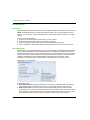
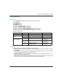
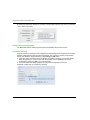
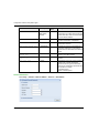
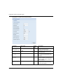
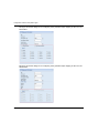
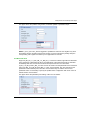
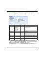
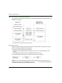
The technical characteristics of the devices described in this document also appear online. To
access this information online:
Step
Action
1
Go to the Schneider Electric home page www.schneider-electric.com.
2
In the Search box type the reference of a product or the name of a product range.
Do not include blank spaces in the model number/product range.
To get information on grouping similar modules, use asterisks (*).
3
If you entered a reference, go to the Product datasheets search results and click on the
reference that interests you.
If you entered the name of a product range, go to the Product Ranges search results and click
on the product range that interests you.
4
If more than one reference appears in the Products search results, click on the reference that
interests you.
5
Depending on the size of your screen, you may need to scroll down to see the data sheet.
6
To save or print a data sheet as a .pdf file, click Download XXX product datasheet.
The characteristics that are presented in this manual should be the same as those characteristics
that appear online. In line with our policy of constant improvement, we may revise content over time
to improve clarity and accuracy. If you see a difference between the manual and online information,
use the online information as your reference.
The information provided in this documentation contains general descriptions and/or technical
characteristics of the performance of the products contained herein. This documentation is not
intended as a substitute for and is not to be used for determining suitability or reliability of these
products for specific user applications. It is the duty of any such user or integrator to perform the
appropriate and complete risk analysis, evaluation and testing of the products with respect to the
relevant specific application or use thereof. Neither Schneider Electric nor any of its affiliates or
subsidiaries shall be responsible or liable for misuse of the information contained herein. If you
have any suggestions for improvements or amendments or have found errors in this publication,
please notify us.
No part of this document may be reproduced in any form or by any means, electronic or
mechanical, including photocopying, without express written permission of Schneider Electric.
All pertinent state, regional, and local safety regulations must be observed when installing and
using this product. For reasons of safety and to help ensure compliance with documented system
data, only the manufacturer should perform repairs to components.
When devices are used for applications with technical safety requirements, the relevant
instructions must be followed.
Failure to use Schneider Electric software or approved software with our hardware products may
result in injury, harm, or improper operating results.
Failure to observe this information can result in injury or equipment damage.
© 2014 Schneider Electric. All rights reserved.
2
EIO0000000505 04/2014
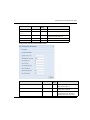
Table of Contents
Safety Information . . . . . . . . . . . . . . . . . . . . . . . . . . . . .
About the Book. . . . . . . . . . . . . . . . . . . . . . . . . . . . . . . .
Part I The RTU Module for M340 Platforms . . . . . . . . . .
Chapter 1 About the BMX NOR 0200 H Module. . . . . . . . . . . . . . .
Introducing the BMX NOR 0200 H Module . . . . . . . . . . . . . . . . . . . . .
Part II BMX NOR 0200 H Hardware Characteristics . . . .
Chapter 2 Hardware Presentation . . . . . . . . . . . . . . . . . . . . . . . . .
Physical Description . . . . . . . . . . . . . . . . . . . . . . . . . . . . . . . . . . . . . .
Module Dimensions . . . . . . . . . . . . . . . . . . . . . . . . . . . . . . . . . . . . . . .
LED Indicators . . . . . . . . . . . . . . . . . . . . . . . . . . . . . . . . . . . . . . . . . . .
Ethernet Port . . . . . . . . . . . . . . . . . . . . . . . . . . . . . . . . . . . . . . . . . . . .
Serial Port . . . . . . . . . . . . . . . . . . . . . . . . . . . . . . . . . . . . . . . . . . . . . .
Electrical Characteristics . . . . . . . . . . . . . . . . . . . . . . . . . . . . . . . . . . .
Rack Position. . . . . . . . . . . . . . . . . . . . . . . . . . . . . . . . . . . . . . . . . . . .
Chapter 3 Hardware Installation . . . . . . . . . . . . . . . . . . . . . . . . . . .
Installing a Module. . . . . . . . . . . . . . . . . . . . . . . . . . . . . . . . . . . . . . . .
Grounding of Installed Modules. . . . . . . . . . . . . . . . . . . . . . . . . . . . . .
SD Memory Card . . . . . . . . . . . . . . . . . . . . . . . . . . . . . . . . . . . . . . . . .
Modicon M340H (Hardened) Equipment . . . . . . . . . . . . . . . . . . . . . . .
Wiring Considerations . . . . . . . . . . . . . . . . . . . . . . . . . . . . . . . . . . . . .
Part III Communications Characteristics . . . . . . . . . . . . .
Chapter 4 Ethernet Communications. . . . . . . . . . . . . . . . . . . . . . .
4.1 Ethernet Services . . . . . . . . . . . . . . . . . . . . . . . . . . . . . . . . . . . . . . . .
Ethernet Services Overview . . . . . . . . . . . . . . . . . . . . . . . . . . . . . . . .
4.2 IP Parameters . . . . . . . . . . . . . . . . . . . . . . . . . . . . . . . . . . . . . . . . . . .
Methods for IP Addressing . . . . . . . . . . . . . . . . . . . . . . . . . . . . . . . . .
Rotary Switches. . . . . . . . . . . . . . . . . . . . . . . . . . . . . . . . . . . . . . . . . .
Deriving IP Parameters from the MAC Address . . . . . . . . . . . . . . . . .
4.3 Modbus TCP/IP Messaging. . . . . . . . . . . . . . . . . . . . . . . . . . . . . . . . .
Data Exchange . . . . . . . . . . . . . . . . . . . . . . . . . . . . . . . . . . . . . . . . . .
The Messaging Configuration Tab . . . . . . . . . . . . . . . . . . . . . . . . . . .
Messaging Configuration Parameters . . . . . . . . . . . . . . . . . . . . . . . . .
EIO0000000505 04/2014
9
11
13
15
15
19
21
22
24
25
27
29
31
32
33
34
36
38
40
41
43
45
46
46
48
49
50
52
54
55
56
57
3
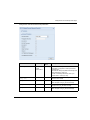
4.4 SNMP. . . . . . . . . . . . . . . . . . . . . . . . . . . . . . . . . . . . . . . . . . . . . . . . . .
SNMP and Schneider Private MIB Overview . . . . . . . . . . . . . . . . . . . .
SNMP Communication. . . . . . . . . . . . . . . . . . . . . . . . . . . . . . . . . . . . .
SNMP Operations Example . . . . . . . . . . . . . . . . . . . . . . . . . . . . . . . . .
4.5 SOAP Web Services . . . . . . . . . . . . . . . . . . . . . . . . . . . . . . . . . . . . . .
Designing a SOAP Client Interface . . . . . . . . . . . . . . . . . . . . . . . . . . .
Chapter 5 Serial Communications . . . . . . . . . . . . . . . . . . . . . . . . .
Serial Port . . . . . . . . . . . . . . . . . . . . . . . . . . . . . . . . . . . . . . . . . . . . . .
Serial Communication Architectures . . . . . . . . . . . . . . . . . . . . . . . . . .
Chapter 6 Modem Communications . . . . . . . . . . . . . . . . . . . . . . .
Modem Communication . . . . . . . . . . . . . . . . . . . . . . . . . . . . . . . . . . . .
Modem Support . . . . . . . . . . . . . . . . . . . . . . . . . . . . . . . . . . . . . . . . . .
Modem Register Command . . . . . . . . . . . . . . . . . . . . . . . . . . . . . . . . .
Modem Communication Error Codes. . . . . . . . . . . . . . . . . . . . . . . . . .
Connecting External Modem (RS232) . . . . . . . . . . . . . . . . . . . . . . . . .
How to work with External Modem. . . . . . . . . . . . . . . . . . . . . . . . . . . .
Part IV Functional Description . . . . . . . . . . . . . . . . . . . . .
Chapter 7 How to Work with RTU Protocols . . . . . . . . . . . . . . . . .
7.1 RTU Protocols . . . . . . . . . . . . . . . . . . . . . . . . . . . . . . . . . . . . . . . . . . .
Communication Protocols . . . . . . . . . . . . . . . . . . . . . . . . . . . . . . . . . .
IEC 60870-5-101/104 Protocols Overview. . . . . . . . . . . . . . . . . . . . . .
DNP3 Protocols Overview . . . . . . . . . . . . . . . . . . . . . . . . . . . . . . . . . .
7.2 Clock Synchronization . . . . . . . . . . . . . . . . . . . . . . . . . . . . . . . . . . . . .
Clock Synchronization with the RTU Protocol Facilities. . . . . . . . . . . .
Clock Synchronization with the NTP Protocol . . . . . . . . . . . . . . . . . . .
7.3 Time Stamping . . . . . . . . . . . . . . . . . . . . . . . . . . . . . . . . . . . . . . . . . . .
Event Time Stamping. . . . . . . . . . . . . . . . . . . . . . . . . . . . . . . . . . . . . .
7.4 Events Management . . . . . . . . . . . . . . . . . . . . . . . . . . . . . . . . . . . . . .
Overview . . . . . . . . . . . . . . . . . . . . . . . . . . . . . . . . . . . . . . . . . . . . . . .
Events Routing. . . . . . . . . . . . . . . . . . . . . . . . . . . . . . . . . . . . . . . . . . .
Events Backup . . . . . . . . . . . . . . . . . . . . . . . . . . . . . . . . . . . . . . . . . . .
7.5 Integrity Poll Command . . . . . . . . . . . . . . . . . . . . . . . . . . . . . . . . . . . .
Integrity Poll Command . . . . . . . . . . . . . . . . . . . . . . . . . . . . . . . . . . . .
7.6 Transmission Modes . . . . . . . . . . . . . . . . . . . . . . . . . . . . . . . . . . . . . .
Overview . . . . . . . . . . . . . . . . . . . . . . . . . . . . . . . . . . . . . . . . . . . . . . .
7.7 Connection Status . . . . . . . . . . . . . . . . . . . . . . . . . . . . . . . . . . . . . . . .
Overview . . . . . . . . . . . . . . . . . . . . . . . . . . . . . . . . . . . . . . . . . . . . . . .
4
58
59
60
62
63
63
65
66
67
69
70
71
73
75
76
78
83
85
86
87
88
90
92
93
94
97
97
98
99
101
106
109
109
112
112
113
113
EIO0000000505 04/2014
7.8 Communication Error Codes . . . . . . . . . . . . . . . . . . . . . . . . . . . . . . . .
RTU Protocols Communication Error Codes . . . . . . . . . . . . . . . . . . . .
Chapter 8 How to Work with Datalogging Service . . . . . . . . . . . .
About Datalogging Service . . . . . . . . . . . . . . . . . . . . . . . . . . . . . . . . .
Create a Datalogging Service . . . . . . . . . . . . . . . . . . . . . . . . . . . . . . .
Datalogging Properties . . . . . . . . . . . . . . . . . . . . . . . . . . . . . . . . . . . .
Datalogging Configuration . . . . . . . . . . . . . . . . . . . . . . . . . . . . . . . . . .
Datalogging File Format . . . . . . . . . . . . . . . . . . . . . . . . . . . . . . . . . . .
Recommendation on Datalogging Service . . . . . . . . . . . . . . . . . . . . .
Chapter 9 How to Work with Email/SMS Service . . . . . . . . . . . . .
About the Email Service / SMS Service . . . . . . . . . . . . . . . . . . . . . . .
Create an Email Service . . . . . . . . . . . . . . . . . . . . . . . . . . . . . . . . . . .
Email Properties . . . . . . . . . . . . . . . . . . . . . . . . . . . . . . . . . . . . . . . . .
Email Configuration . . . . . . . . . . . . . . . . . . . . . . . . . . . . . . . . . . . . . . .
Chapter 10 How to Work with Embedded Web Pages . . . . . . . . . .
10.1 Embedded Web Pages . . . . . . . . . . . . . . . . . . . . . . . . . . . . . . . . . . . .
Introduction to Embedded Web Pages . . . . . . . . . . . . . . . . . . . . . . . .
10.2 Home Web Page . . . . . . . . . . . . . . . . . . . . . . . . . . . . . . . . . . . . . . . . .
Home Page . . . . . . . . . . . . . . . . . . . . . . . . . . . . . . . . . . . . . . . . . . . . .
10.3 Setup Web Pages . . . . . . . . . . . . . . . . . . . . . . . . . . . . . . . . . . . . . . . .
Module Setup . . . . . . . . . . . . . . . . . . . . . . . . . . . . . . . . . . . . . . . . . . .
Security . . . . . . . . . . . . . . . . . . . . . . . . . . . . . . . . . . . . . . . . . . . . . . . .
FTP Security Page . . . . . . . . . . . . . . . . . . . . . . . . . . . . . . . . . . . . . . .
10.4 Diagnostics Web Pages . . . . . . . . . . . . . . . . . . . . . . . . . . . . . . . . . . .
Diagnostics . . . . . . . . . . . . . . . . . . . . . . . . . . . . . . . . . . . . . . . . . . . . .
PLC Rack Viewer Page . . . . . . . . . . . . . . . . . . . . . . . . . . . . . . . . . . . .
Messaging . . . . . . . . . . . . . . . . . . . . . . . . . . . . . . . . . . . . . . . . . . . . . .
NTP Diagnostics . . . . . . . . . . . . . . . . . . . . . . . . . . . . . . . . . . . . . . . . .
Clock Diagnostics . . . . . . . . . . . . . . . . . . . . . . . . . . . . . . . . . . . . . . . .
Statistics . . . . . . . . . . . . . . . . . . . . . . . . . . . . . . . . . . . . . . . . . . . . . . .
Upload MIB File . . . . . . . . . . . . . . . . . . . . . . . . . . . . . . . . . . . . . . . . . .
Properties . . . . . . . . . . . . . . . . . . . . . . . . . . . . . . . . . . . . . . . . . . . . . .
10.5 Monitoring Web Pages . . . . . . . . . . . . . . . . . . . . . . . . . . . . . . . . . . . .
Monitoring . . . . . . . . . . . . . . . . . . . . . . . . . . . . . . . . . . . . . . . . . . . . . .
Data Editor. . . . . . . . . . . . . . . . . . . . . . . . . . . . . . . . . . . . . . . . . . . . . .
Part V Configuring the Module . . . . . . . . . . . . . . . . . . . . .
Chapter 11 Configuring the Module . . . . . . . . . . . . . . . . . . . . . . . . .
Configuration Methodology . . . . . . . . . . . . . . . . . . . . . . . . . . . . . . . . .
EIO0000000505 04/2014
114
114
115
116
118
119
121
125
126
127
128
130
131
133
137
138
138
139
139
140
141
142
144
145
146
147
149
150
151
152
154
155
156
157
158
159
161
161
5
Chapter 12 Configuration and Debug with Unity Pro . . . . . . . . . . .
12.1 Configuration with Unity Pro. . . . . . . . . . . . . . . . . . . . . . . . . . . . . . . . .
Configuring with Unity Pro . . . . . . . . . . . . . . . . . . . . . . . . . . . . . . . . . .
Configuration Screen . . . . . . . . . . . . . . . . . . . . . . . . . . . . . . . . . . . . . .
12.2 Debugging with Unity Pro. . . . . . . . . . . . . . . . . . . . . . . . . . . . . . . . . . .
Module Debugging Screen. . . . . . . . . . . . . . . . . . . . . . . . . . . . . . . . . .
General Debugging Parameters . . . . . . . . . . . . . . . . . . . . . . . . . . . . .
Debugging Parameters for TCP/IP Utilities . . . . . . . . . . . . . . . . . . . . .
Chapter 13 Configuration with the Setup Web Pages . . . . . . . . . .
13.1 Web Site Configuration Common. . . . . . . . . . . . . . . . . . . . . . . . . . . . .
Parameter Input Interface in Setup Web Pages. . . . . . . . . . . . . . . . . .
Channel Configuration . . . . . . . . . . . . . . . . . . . . . . . . . . . . . . . . . . . . .
Serial Port Configuration . . . . . . . . . . . . . . . . . . . . . . . . . . . . . . . . . . .
Ethernet Port Configuration . . . . . . . . . . . . . . . . . . . . . . . . . . . . . . . . .
Time Zone Configuration . . . . . . . . . . . . . . . . . . . . . . . . . . . . . . . . . . .
RTU Protocol Parameters . . . . . . . . . . . . . . . . . . . . . . . . . . . . . . . . . .
Module and Protocols Configuration File . . . . . . . . . . . . . . . . . . . . . . .
RTU Protocol Service Reset . . . . . . . . . . . . . . . . . . . . . . . . . . . . . . . .
Upward Compatibility . . . . . . . . . . . . . . . . . . . . . . . . . . . . . . . . . . . . . .
13.2 Web Site Configuration IEC . . . . . . . . . . . . . . . . . . . . . . . . . . . . . . . . .
IEC 60870-5-101 Master RTU Protocol Parameters . . . . . . . . . . . . . .
IEC 60870-5-101 Slave RTU Protocol Parameters . . . . . . . . . . . . . . .
IEC 60870-5-104 Client RTU Protocol Parameters . . . . . . . . . . . . . . .
IEC 60870-5-104 Server RTU Protocol Parameters . . . . . . . . . . . . . .
IEC Data Object Mapping Page and Table . . . . . . . . . . . . . . . . . . . . .
IEC Data Object Mapping . . . . . . . . . . . . . . . . . . . . . . . . . . . . . . . . . .
IEC Event Queue Setting . . . . . . . . . . . . . . . . . . . . . . . . . . . . . . . . . . .
IEC 60870-5-101/104 Master/Client. . . . . . . . . . . . . . . . . . . . . . . . . . .
IEC Data Length & Mapping Orientation . . . . . . . . . . . . . . . . . . . . . . .
IEC Data Object Type Mapped to Unity Pro EDT/DDT . . . . . . . . . . . .
13.3 Web Site Configuration DNP3 . . . . . . . . . . . . . . . . . . . . . . . . . . . . . . .
DNP3 Master/DNP3 NET Client RTU Protocol Parameters . . . . . . . .
DNP3 Slave/Server RTU Protocol Parameters . . . . . . . . . . . . . . . . . .
DNP3 Channel Configuration Over UDP . . . . . . . . . . . . . . . . . . . . . . .
DNP3 Data Object Mapping Page and Table . . . . . . . . . . . . . . . . . . .
DNP3 Data Object Mapping. . . . . . . . . . . . . . . . . . . . . . . . . . . . . . . . .
6
163
164
165
167
169
170
171
173
175
176
177
180
185
192
193
195
196
199
200
201
202
209
217
222
229
239
241
243
245
246
249
250
256
262
266
281
EIO0000000505 04/2014
DNP3 Event Queue Setting. . . . . . . . . . . . . . . . . . . . . . . . . . . . . . . . .
DNP3 Master/ DNP3 Net Client. . . . . . . . . . . . . . . . . . . . . . . . . . . . . .
DNP3 Data Length & Mapping Orientation . . . . . . . . . . . . . . . . . . . . .
DNP3 Data Object Type Mapped to Unity Pro EDT/DDT . . . . . . . . . .
Chapter 14 Web Designer Configuration . . . . . . . . . . . . . . . . . . . . .
Create a Project. . . . . . . . . . . . . . . . . . . . . . . . . . . . . . . . . . . . . . . . . .
PLC Device Configuration . . . . . . . . . . . . . . . . . . . . . . . . . . . . . . . . . .
Data Editor Configuration . . . . . . . . . . . . . . . . . . . . . . . . . . . . . . . . . .
Transfer . . . . . . . . . . . . . . . . . . . . . . . . . . . . . . . . . . . . . . . . . . . . . . . .
Appendices
.........................................
Appendix A Interoperability . . . . . . . . . . . . . . . . . . . . . . . . . . . . . . . .
IEC 60870-5-101 Interoperability for BMX NOR 0200 H as Master . .
IEC 60870-5-101 Interoperability for BMX NOR 0200 H as Slave . . .
IEC 60870-5-104 Interoperability for BMX NOR 0200 H as Client . . .
IEC 60870-5-104 Interoperability for BMX NOR 0200 H as Server. . .
DNP3 Interoperability for BMX NOR 0200 H as Master . . . . . . . . . . .
DNP3 Interoperability for BMX NOR 0200 H as Slave . . . . . . . . . . . .
Appendix B Ethernet Language Objects. . . . . . . . . . . . . . . . . . . . . .
B.1
B.2
B.3
Glossary
Index
EIO0000000505 04/2014
Language Objects and IODDTs of Ethernet Communication . . . . . . .
Language Objects and IODDTs of Ethernet Communication . . . . . . .
Implicit Exchange Language Objects Associated with the ApplicationSpecific Function . . . . . . . . . . . . . . . . . . . . . . . . . . . . . . . . . . . . . . . . .
Explicit Exchange Language Objects Associated with the ApplicationSpecific Function . . . . . . . . . . . . . . . . . . . . . . . . . . . . . . . . . . . . . . . . .
Exchange Objects of Type T_COM_ETH_BMX . . . . . . . . . . . . . . . . .
Details of Implicit Exchange Objects of the IODDT Type
T_COM_ETH_BMX . . . . . . . . . . . . . . . . . . . . . . . . . . . . . . . . . . . . . . .
Details of Explicit Exchange Objects of the IODDT Type
T_COM_ETH_BMX . . . . . . . . . . . . . . . . . . . . . . . . . . . . . . . . . . . . . . .
Details of Explicit Exchange Objects of the Non-IODDT Type
T_COM_ETH_BMX . . . . . . . . . . . . . . . . . . . . . . . . . . . . . . . . . . . . . . .
Language Objects Associated with BMX NOR 0200 H Module
Configuration . . . . . . . . . . . . . . . . . . . . . . . . . . . . . . . . . . . . . . . . . . . .
Language Objects for Implicit Exchange . . . . . . . . . . . . . . . . . . . . . . .
Language Objects for Explicit Exchange . . . . . . . . . . . . . . . . . . . . . . .
.........................................
.........................................
286
288
290
291
295
296
299
300
301
303
305
306
316
326
335
344
355
369
370
371
372
373
375
376
377
379
380
381
382
385
395
7
8
EIO0000000505 04/2014
Safety Information
Important Information
NOTICE
Read these instructions carefully, and look at the equipment to become familiar with the device
before trying to install, operate, or maintain it. The following special messages may appear
throughout this documentation or on the equipment to warn of potential hazards or to call attention
to information that clarifies or simplifies a procedure.
EIO0000000505 04/2014
9
PLEASE NOTE
Electrical equipment should be installed, operated, serviced, and maintained only by qualified
personnel. No responsibility is assumed by Schneider Electric for any consequences arising out of
the use of this material.
A qualified person is one who has skills and knowledge related to the construction and operation
of electrical equipment and its installation, and has received safety training to recognize and avoid
the hazards involved.
10
EIO0000000505 04/2014
About the Book
At a Glance
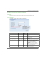
Document Scope
This guide explains the architectures and features supported by the in-rack BMX NOR 0200 H
module for the Modicon M340 PAC modular controller platform. This guide includes instructions
for setting up RTU functions and protocols that are used in various telemetry and supervisory
control and data acquisition (SCADA) applications, such as: water and wastewater, oil and gas,
power and hydropower, other distributed infrastructures.
Validity Note
This document is valid from Unity Pro V8.0.
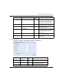
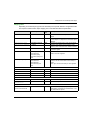
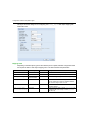
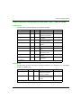
Related Documents
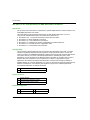
Title of Documentation
Reference Number
Modicon M340 using Unity Pro: Processors, Racks and Power
Supply Modules
35012676 (Eng), 35012677 (Fre),
35013351 (Ger), 35013352 (Ita),
35013353 (Spa)
You can download these technical publications and other technical information from our website
at www.schneider-electric.com.
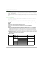
Product Related Information
WARNING
UNINTENDED EQUIPMENT OPERATION
The application of this product requires expertise in the design and programming of control
systems. Only persons with such expertise should be allowed to program, install, alter, and apply
this product.
Follow all local and national safety codes and standards.
Failure to follow these instructions can result in death, serious injury, or equipment
damage.
EIO0000000505 04/2014
11
12
EIO0000000505 04/2014
Modicon M340 RTU
The RTU Module for M340 Platforms
EIO0000000505 04/2014
Part I
The RTU Module for M340 Platforms
The RTU Module for M340 Platforms
EIO0000000505 04/2014
13
The RTU Module for M340 Platforms
14
EIO0000000505 04/2014
Modicon M340 RTU
About the BMX NOR 0200 H Module
EIO0000000505 04/2014
Chapter 1
About the BMX NOR 0200 H Module
About the BMX NOR 0200 H Module
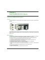
Introducing the BMX NOR 0200 H Module
Overview
The BMX NOR 0200 H module brings Remote Terminal Unit (RTU) functionality to the M340 PAC
platform.
The M340 RTU system provides an extensive set of control and communications features including
industry and telemetry standard protocols such as IEC 60870-5-101, IEC 60870-5-104, DNP3 and
Modbus TCP.
About the Module
The M340 PAC controller and its built-in RTU module are designed for installation and operation
in harsh environments and extended operating temperature ranges (see page 40).
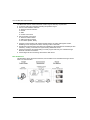
The Modicon M340 PAC controller platform offers these features for telemetry applications:
operations in extended temperature ranges and harsh environments
in-rack RTU module with support for IEC 60870-5-101/104, DNP3, and Modbus TCP
specialized function blocks (AGA, flow calculations)
expandable rack-based modular I/O configurations and remote I/O capabilities
high-density, discrete, analog, and I/O counting modules
isolated input power supply (various voltage ranges available 24, 24/48 VDC, 125 DC 1000/240
VAC)
built-in CPU and modules with serial and Ethernet communication ports
support for Modbus TCP
local or remote downloading of operating system firmware
EIO0000000505 04/2014
15
About the BMX NOR 0200 H Module
The BMX NOR 0200 H module addresses a wide range of telemetry requirements:
conformal coating and extended operating temperature ranges
various communications methods
serial and TCP/IP networks
intranet
WAN
modem connections
various modem connections
serial and radio modems
GSM and PSTN modems
IP modems (GPRS, ADSL)
upstream communications with SCADA master stations for polling interrogation of data,
backfilling of time stamped event data, receiving master commands
downstream communications with other RTU substations, slave field devices and IEDs (for data
collection), sending commands, and synchronizing distributed control
remote programming and downloading of control program with Unity Pro software through
Ethernet or modem connections
remote diagnostic and monitoring with a built-in Web server
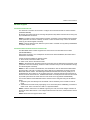
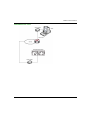
RTU Architecture
This illustration shows the RTU architecture, from SCADA to RTU substations through various
means of communication:
16
EIO0000000505 04/2014
About the BMX NOR 0200 H Module
Functions and Protocols
The BMX NOR 0200 H module supports these functions and protocols:
RTU protocols:
Built-in RTU protocols for serial or Ethernet communications
IEC 60870-5-101 (master or slave)
IEC 60870-5-104 (client or server)
DNP3 serial (master or slave)
DNP3 IP (client or server)
Modbus TCP (client or server)
Main RTU Protocol Features
Time synchronization through protocol facility or NTP
Data synchronization on demand of the SCADA
Balanced and unbalanced transmission mode
Events management with time stamping - Sequence of Events (SOE)
Events queue stored in RAM memory (up to 100,000 events for all clients)
Events data backfill to SCADA application via protocol facility
Report by exception data exchanges
Unsolicited messaging data exchanges
Protocol setup via Web page
Other built-in functions
Historical datalogging with time stamping inside the module’s SD memory card
Email/SMS notifications
Web server for RTU set-up and remote diagnostic and monitoring
Advanced TCP/IP networking: NTP client, FTP client or server, HTTP server, SOAP/XML,
communication server, SNMP agent, SMTP client.
NOTE: When the BMX NOR 0200 H module works as IEC-104/DNP3 Client, the number of
connected servers affects the module performance (web page access, module start-up and data
exchange through the backplane.)
EIO0000000505 04/2014
17
About the BMX NOR 0200 H Module
18
EIO0000000505 04/2014
Modicon M340 RTU
Hardware Characteristics
EIO0000000505 04/2014
Part II
BMX NOR 0200 H Hardware Characteristics
BMX NOR 0200 H Hardware Characteristics
About this Part
This part contains an overview of hardware characteristics for the BMX NOR 0200 H module.
For Modicon M340 system installation and specifications, see the book Modicon M340 using Unity
Pro: Processors, Racks and Power Supply Modules.
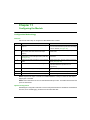
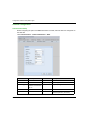
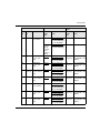
What Is in This Part?
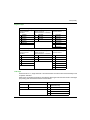
This part contains the following chapters:
Chapter
Chapter Name
Page
2
Hardware Presentation
21
3
Hardware Installation
33
EIO0000000505 04/2014
19
Hardware Characteristics
20
EIO0000000505 04/2014
Modicon M340 RTU
Hardware Presentation
EIO0000000505 04/2014
Chapter 2
Hardware Presentation
Hardware Presentation
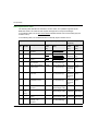
What Is in This Chapter?
This chapter contains the following topics:
Topic
Page
Physical Description
22
Module Dimensions
24
LED Indicators
25
Ethernet Port
27
Serial Port
29
Electrical Characteristics
31
Rack Position
32
EIO0000000505 04/2014
21
Hardware Presentation
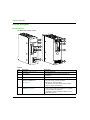
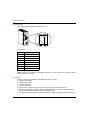
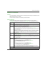
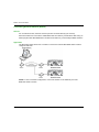
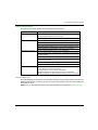
Physical Description
External Features
The BMX NOR 0200 H module:
6
1
MAC Address:
00
00-00-00-00-00-00-
7
2
8
3
4
9
Ethernet
5
10
Serial
Callouts:
22
Item
Description
Description
1
LED display (see page 25)
diagnostic indications
2
MAC Address
unique address for each module, defined by the
manufacturer
3
Memory card slot (see page 38)
SD card can store Web site files and datalogging CSV files
4
Ethernet port (RJ45 connector,
10BASE-T/100BASE-TX)
(see page 27)
Functions include:
Ethernet TCP/IP network connection
Modbus TCP protocol support
IEC 60870-5-104, DNP3 NET protocols support
Unity Pro remote programming
5
Serial port (RS 232C/RS 485, nonisolated) (see page 66)
Functions include:
serial communications: IEC 60870-5-101 or DNP3
external modem management
PPP/Modem communication: IEC 60870-5-104 or
DNP3 NET protocol
EIO0000000505 04/2014
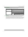
Hardware Presentation
Item
Description
Description
6
Ground connection
contact by screw tightening
7
Ground connection
contact by CEM clip 1
8
Rack connector
plug to the a M340 rack
9
Rotary switches (see page 50)
two rotary switches to provide a simple way to select an IP
address
10
Ground connection
contact by CEM clip 2
EIO0000000505 04/2014
23
Hardware Presentation
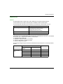
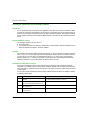
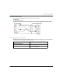
Module Dimensions
Dimensions
The dimensions of the Modicon M340 BMX NOR 0200 H module conform to the characteristics of
the BMX XBP rack.:
112.8
mm
in.
32
1.25
24
94.3
3.71
100
3.93
103.76
4.08
4.44
86
3.38
EIO0000000505 04/2014
Hardware Presentation
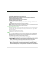
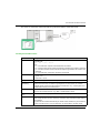
LED Indicators
Introduction
The LED indicators are located on the front of the BMX NOR 0200 H module (see page 22). LEDs
provide information on:
the memory card
communication with the modules
serial communication
communication on the Ethernet network
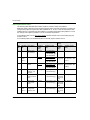
LED Descriptions
This illustration shows the diagnostic LEDs on the BMX NOR 0200 H module:
The colors and blink patterns of the LEDs indicate the status and operating conditions of Ethernet
communications on the module:
Label
Pattern
Indication
RUN (green): operational state
on
The module is operating and configured.
flashing
The module is blocked by a detected software error.
off
The module is not configured. (The application is absent, invalid,
or incompatible.)
on
The processor, system, or configuration detected an error.
flashing
The module is not configured. (The application is absent,
ERR (red): detected error
invalid, or incompatible.)
The module is blocked by a detected software error.
DL (red): download firmware
(upgrade)
off
Operations are normal (no detected errors).
on
Firmware download is in progress.
off
Firmware download is not in progress.
SER COM (yellow): serial data status flashing
CARDERR (red): memory card
detected error
Data exchange (send/receive) on the serial connection is in
progress.
off
There is no data exchange on the serial connection.
on
The memory card is missing.
The memory card is not usable (bad format, unrecognized
type).
off
EIO0000000505 04/2014
The memory card is valid and recognized.
25
Hardware Presentation
Label
Pattern
Indication
ETH ACT (green): Ethernet
communication
(transmission/reception) activity
on
Communication activity is detected.
off
No communication activity is detected.
ETH STS (green): Ethernet
communication status
on
Communication is OK.
2 flashes
A MAC address is not valid.
3 flashes
The link is not connected.
4 flashes
There is a duplicate IP address.
5 flashes
The module is waiting for a server IP address.
6 flashes
The module is in secure and safe mode (with default IP address).
7 flashes
There is a configuration mismatch between the rotary switches
and the internal configuration.
ETH LNK (green): Ethernet link status on
off
An Ethernet link is detected.
An Ethernet link is not detected.
NOTE 1: Rapid flashing is defined as ON for 50 ms and OFF for 50 ms.
NOTE 2: Slow flashing is defined as ON for 200 ms and OFF for 200 ms.
26
EIO0000000505 04/2014
Hardware Presentation
Ethernet Port
General
The BMX NOR 0200 H module has a built-in Ethernet port supporting either Ethernet
communications via a modem communication or Modbus TCP/IP communication.
The following table describes the characteristics of the Ethernet communication channel:.
Characteristic
Description
Protocols supported
RTU protocols:
IEC 60870-5-104 (client or server)
DNP3 NET (client or server)
Modbus TCP/IP (client or server)
Connection
RJ45 female connector
Physical link
Ethernet 802.3 - Ethernet II
The Ethernet port on the BMX NOR 0200 H module is a standard RJ45 connector. In an industrial
environment, use a cable with the following characteristics:
shielded twisted double pair
impedance 100 Ω±15 Ω (from 1 to 16 MHz)
maximum attenuation 11.5 dB/100 meters
maximum length 100 meters
The following straight-through ConneXium cables fit these requirements for connecting terminal
devices:
Description
Straight-through
cable with RJ45
ends
EIO0000000505 04/2014
Reference
Length, m (ft)
Low Smoke Zero
Halogen
UL/CSA CMG
490 NTW 000 02
490 NTW 000 02 U
2 (6.6)
490 NTW 000 05
490 NTW 000 05 U
5 (16.4)
490 NTW 000 12
490 NTW 000 12 U
12 (39.4)
490 NTW 000 40
490 NTW 000 40 U
40 (131.2)
490 NTW 000 80
490 NTW 000 80 U
80 (262.5)
27
Hardware Presentation
Pin Assignment
The following illustration shows the Ethernet port:
MAC Address:
00
00-00-00-00-00-00-
Ethernet
1
2
3
4
5
6
7
8
Serial
Pinout table:
Pin
Signal
1
TD+
2
TD-
3
RD+
4
not connected
5
not connected
6
RD-
7
not connected
8
not connected
NOTE: If there is a connection via a shielded cable, the connector casing on the module is linked
up to the ground connection.
Line Speed
These line speeds are available for the BMX NOR 0200 H module:
100 Mb in half duplex
100 Mb in full duplex
10 Mb in half duplex
10 Mb in full duplex
The user can not configure the line speed. Characteristics of speed adaptation are:
Auto-sensing and auto-negotiation allow the BMX NOR 0200 H module to quickly configure
itself to the local Ethernet switch’s speed and duplex mode.
The negotiated speed between two Ethernet devices is limited to the speed of the slower device.
28
EIO0000000505 04/2014
Hardware Presentation
Serial Port
General
The BMX NOR 0200 H module has a built-in serial port supporting either serial communications
via a serial link or modem communications via an external modem device (see page 65).
The following table describes the serial communication channels:
Characteristic
Description
Protocols supported
RTU protocols:
IEC 60870-5-101
IEC 60870-5-104 (PPP/Modem)
DNP3 serial
DNP3 NET (PPP/Modem)
Connection
RJ45 female connector
Physical link
RS 485 non-insulated serial link
RS 232 non-insulated serial link
Pin Assignment
The following illustration shows the RJ45 serial port:
MAC Address:
00
00-00-00-00-00-00-
1
2
3
4
5
6
7
8
Ethernet
Serial
Pin
Signal
Pin
Signal
1
RXD
5
D0
2
TXD
6
CTS
3
RTS
7
Power supply
4
D1
8
Common
Shielding
EIO0000000505 04/2014
29
Hardware Presentation
The RJ45 connector has eight pins. The pins used differ according to the physical link used.
The pins used by the RS 232 serial link are as follows:
Pin 1: RXD signal
Pin 2: TXD signal
Pin 3: RTS signal
Pin 6: CTS signal
The pins used by the RS 485 serial link are as follows:
Pin 4: D1 signal
Pin 5: D0 signal
Pins 7 and 8 are dedicated to the power supply of the man-machine interface via the serial link:
Pin 7: 5 VDC/190 mA network power supply
Pin 8: common of the network power supply (0 V)
NOTE: The RS 232 4-wire, RS 485 2-wire, and RS 485 2-wire and power supply cables use the
same RJ45 male connector.
30
EIO0000000505 04/2014
Hardware Presentation
Electrical Characteristics
Consumed Current
The BMX NOR 0200 H module can be inserted into any rack slot on the BMX XB• station assembly
(see page 32).
This list shows the current that the BMX NOR 0200 H module consumes from the 24 VDC rack
power and the residual dissipated power:
BMX NOR 0200 H
Consumed current:
95 mA
Dissipated power
2.2 W
EIO0000000505 04/2014
31
Hardware Presentation
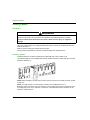
Rack Position
Introduction
This topic describes the appropriate rack positions of the BMX NOR 0200 H module on a BMX XB•
station assembly during installation (see page 33).
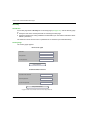
Rack Position
Mechanically, it is possible to position the BMX NOR 0200 H module in any available slot.
The following rack assembly includes a M340 CPU (in this case a BMX P34 2020) and a
BMX NOR 0200 H module. Rack positions 0 to 8 are indicated. (The double-wide power supply is
mounted at the beginning of the rack.)
0
0
1
2
3
4-7
8
1
2
3
4
5
6
7
8
BMX P34 2020 at rack position 0
discrete I/O module at rack position 1
counter module at rack position 2
BMX NOR 0200 H module at rack position 3
available rack positions
extension module at rack position 8
NOTE: Refer to the Modicon M340 Using Unity Pro -- Processors, Racks, and Power Supply
Modules Setup Manual for specific part numbers.
32
EIO0000000505 04/2014
Modicon M340 RTU
Hardware Installation
EIO0000000505 04/2014
Chapter 3
Hardware Installation
Hardware Installation
What Is in This Chapter?
This chapter contains the following topics:
Topic
Page
Installing a Module
34
Grounding of Installed Modules
36
SD Memory Card
38
Modicon M340H (Hardened) Equipment
40
Wiring Considerations
41
EIO0000000505 04/2014
33
Hardware Installation
Installing a Module
Introduction
WARNING
MODULE DESTRUCTION - LOSS OF APPLICATION
Disconnect all power to the rack before the installation of the BMX NOR 0200 H module.
Failure to follow these instructions can result in death, serious injury, or equipment
damage.
This topic provides steps for installing the BMX NOR 0200 H module on the BMX XB• rack of a
Modicon M340 PLC.
Modicon M340 modules are powered by the rack bus.
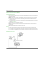
Fitting operations (installation, assembly, and disassembly) are described below.
Installing a module
A BMX NOR 0200 H module is installed on the BMX XB• rack in slot marked 01-08.
The following diagram shows a BMX NOR 0200 H module mounted on a BMX XB• rack in the slot
marked 01 (address 1):
NOTE: Before installing a module, take off the protective cap from the module connector located
on the rack.
NOTE: The total number of communication modules, such as BMX NOE 01•0 or
BMX NOR 0200 H modules, cannot exceed two. The maximum Ethernet port for M340 system is
3 including the port on PLC. Therefore, a maximum of two BMX NOR 0200 H modules can be
inserted in a M340 system.
34
EIO0000000505 04/2014
Hardware Installation
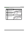
Mounting Instructions
To mount a module on the BMX XB• rack:
Step
Action
1
The following diagram describes steps 1 and 2:
Position the two pins on the
reverse side of the module (at the
bottom) in the corresponding
slots on the rack.
Note: Before positioning the pins,
remove the protective cover.
2
Incline the module towards the
top of the rack so that the module
sits flush with the back of the
rack. It is now set in position.
3
Tighten the safety screw so that The following diagram describes step 3:
the module is held in place on the
rack.
The recommended tightening
torque is between 0.4 and
1.5 Nm.
EIO0000000505 04/2014
Illustration
35
Hardware Installation
Grounding of Installed Modules
General
The grounding of Modicon M340 modules is crucial to avoid electric shock.
Grounding Processors and Power Supplies
DANGER
HAZARD OF ELECTRIC SHOCK, EXPLOSION OR ARC FLASH
Ensure ground connection contacts are present and not bent out of shape. If they are, do not use
the module and contact your Schneider Electric representative.
Failure to follow these instructions will result in death or serious injury.
WARNING
UNINTENDED EQUIPMENT OPERATION
Tighten the clamping screws of the modules. A break in the circuit could lead to an unexpected
behavior of the system.
Failure to follow these instructions can result in death, serious injury, or equipment
damage.
36
EIO0000000505 04/2014
Hardware Installation
All Modicon M340 modules are equipped with ground connection contacts at the rear for grounding
purposes:
These contacts connect the grounding bus of the modules to the grounding bus of the rack.
EIO0000000505 04/2014
37
Hardware Installation
SD Memory Card
Introduction
The Secure Digital (SD) memory card slot is located on the front of the BMX NOR 0200 H module
(see page 22). The BMXRWS128MWF memory card is delivered with the module.
WARNING
RISK OF LOST APPLICATION
Do not remove the memory card from the module while the PLC is running. Remove the memory
card only when the power is off.
Failure to follow these instructions can result in death, serious injury, or equipment
damage.
Card Functionality
This table describes the functionality of the BMXRWS128MWF memory card when inserted into
the BMX NOR 0200 H module:
SD Memory Card
Data Storage
Functionality
BMXRWS128MWF
128 MB
Memory for Web pages
Storage of Datalogging files (CSV)
Card Services
NOTICE
INOPERABLE MEMORY CARD
Do not format the memory card with a non-Schneider tool. The memory card needs a structure
to contain program and data. Formatting with another tool destroys this structure.
Do not use a write-protected memory card with the module. Some services do not operate
properly when the memory card is write-protected.
Failure to follow these instructions can result in equipment damage.
38
EIO0000000505 04/2014
Hardware Installation
Precautions
NOTICE
MEMORY CARD DESTRUCTION
Do not touch the memory card connections.
Keep the memory card away from electrostatic and electromagnetic sources as well as heat,
sunlight, water and moisture.
Avoid impacts to the memory card.
Check the postal service security policy before sending a memory card by postal service. In
some countries the postal service exposes mail to high levels of radiation, as a security
measure. These high levels of radiation may erase the contents of the memory card and
render it unusable.
Failure to follow these instructions can result in equipment damage.
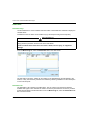
Without SD Memory Card
If no memory card is inserted in the module, you cannot access the website. The following
diagnostic message appears:
Access Error: Site temporarily unavailable. Try again. No SD card
present.
NOTE: The Modicon M340 RTU module works only with a memory card that is present at boot-up
time. A memory card that is inserted during module operations is not recognized.
Although operation is possible without a valid memory card inserted in the module, a valid memory
card should be present at all times in the module.
EIO0000000505 04/2014
39
Hardware Installation
Modicon M340H (Hardened) Equipment
M340H
The Modicon M340H (hardened) equipment is a ruggedized version of M340 equipment. It can be
used at extended temperatures (-25...70ºC) (-13...158ºF) and in harsh chemical environments.
This treatment increases the isolation capability of the circuit boards and their resistance to:
condensation
dusty atmospheres (conducting foreign particles)
chemical corrosion, in particular during use in sulphurous atmospheres (oil, refinery, purification
plant and so on) or atmospheres containing halogens (chlorine and so on)
The M340H equipment, when within the standard temperature range (0...60ºC) (32...140ºF), has
the same performance characteristics as the standard M340 equipment.
At the temperature extremes (-25... 0ºC and 60... 70ºC) (-13...32ºF and 140...158ºF) the hardened
versions can have reduced power ratings that impact power calculations for Unity Pro applications.
If this equipment is operated outside the -25...70ºC (-13...158ºF) temperature range, the
equipment can operate abnormally.
CAUTION
UNINTENDED EQUIPMENT OPERATION
Do not operate M340H equipment outside of its specified temperature range.
Failure to follow these instructions can result in injury or equipment damage.
Hardened equipment has a conformal coating applied to its electronic boards. This protection,
when associated with appropriate installation and maintenance, allows it to be more robust when
operating in harsh chemical environments.
40
EIO0000000505 04/2014
Hardware Installation
Wiring Considerations
The Link
The following situations can create a temporary disruption in the application or communications:
The RJ45 10/100 BASE-T interface connector gets connected or disconnected when the power
is on.
Modules are re-initialized when the power is switched back on.
EIO0000000505 04/2014
41
Hardware Installation
42
EIO0000000505 04/2014
Modicon M340 RTU
Communications Characteristics
EIO0000000505 04/2014
Part III
Communications Characteristics
Communications Characteristics
About this Part
This part describes Ethernet and Serial communications.
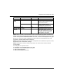
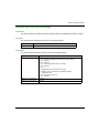
What Is in This Part?
This part contains the following chapters:
Chapter
Chapter Name
Page
4
Ethernet Communications
45
5
Serial Communications
65
6
Modem Communications
69
EIO0000000505 04/2014
43
Communications Characteristics
44
EIO0000000505 04/2014
Modicon M340 RTU
Ethernet Communications
EIO0000000505 04/2014
Chapter 4
Ethernet Communications
Ethernet Communications
What Is in This Chapter?
This chapter contains the following sections:
Section
Topic
Page
4.1
Ethernet Services
46
4.2
IP Parameters
48
4.3
Modbus TCP/IP Messaging
54
4.4
SNMP
58
4.5
SOAP Web Services
63
EIO0000000505 04/2014
45
Ethernet Communications
Section 4.1
Ethernet Services
Ethernet Services
Ethernet Services Overview
Introduction
This topic introduces the different Ethernet services available via the BMX NOR 0200 H module:
Support of Modbus TCP messaging (see page 54)
Support of DNP3 NET and IEC 60870-104 protocols
Built-in HTTP server
Other supported IP protocols:
NTP client
FTP client / server
BootP client, DHCP / FDR client
SNMP agent (see page 58)
SMTP client
SOAP / XML server (see page 63)
Modbus TCP Messaging
This service allows the exchange of data between devices supporting Modbus over TCP/IP.
NMT
The NMT (Network ManagemenT) protocol provides services for network initialization, diagnostic
and control, and also device status control.
46
EIO0000000505 04/2014
Ethernet Communications
NTP
The NMT (Network Time Protocol) is a protocol used for synchronizing the clocks of computer
systems.The time synchronization service establishes time accuracy among devices clocks over
a Ethernet network.
FTP
The FTP (File Transfer Protocol) is the World Wide Web’s file transfer protocol.
BootP
bootstrap protocol. A UDP/IP protocol that allows an Internet node to obtain its IP parameters
based on its MAC address.
DHCP
The DHCP (dynamic host configuration protocol) is a TCP/IP protocol that allows network devices
(DHCP clients) to obtain their IP addresses from a DHCP server through a request to the server.
FDR
The FDR (faulty device replacement) service offers a method of handling device replacement
without disrupting the system nor interrupting service.
SNMP
The SNMP (simple network management protocol) is a UDP/IP standard protocol used to monitor
and manage nodes on an IP network. The SNMP agent supports both the MIB II and the
Transparent Ready Private MIB (see Modicon M340 for Ethernet, Communications Modules and
Processors, User Manual).
SMTP
The SMTP (simple mail transfer protocol) is a transmission protocol for sending e-mail. SMTP
messages are usually retrieved from a server with an e-mail client (such as POP or IMAP).
SOAP / XML server
The SOAP (Single Object Access Protocol) carried via the HTTP (Hyper Text Transfer Protocol)
channel.
EIO0000000505 04/2014
47
Ethernet Communications
Section 4.2
IP Parameters
IP Parameters
About this Section
This section describes the assignment of IP parameters to the BMX NOR 0200 H module. Each
network address must be valid and unique on the network.
What Is in This Section?
This section contains the following topics:
Topic
48
Page
Methods for IP Addressing
49
Rotary Switches
50
Deriving IP Parameters from the MAC Address
52
EIO0000000505 04/2014
Ethernet Communications
Methods for IP Addressing
Overview
You should establish a standard procedure for assigning valid and unique IP addresses for each
M340 module and CPU on a network.
This topic explains the different IP addressing methods available.
Addressing Methods
The BMX NOR 0200 H module can have its IP address set through the rotary switches
(see page 50), the Unity Pro IP Configuration tab (see page 167), or combinations of the two:
Address
Method
Description
STORED
The lower rotary switch is set to STORED (manufacturer default setting), and the module
uses the Unity Pro application’s configured parameters.
device name
(over DHCP)
There are two components of the device name:
default device name of the module: BMX_0200_xxy
numeric value between 00 and 159 set on the rotary switches (see page 50)
(For the default device name, xx is the value of the upper rotary switch and y is the value of
the lower rotary switch.)
Example: For a BMX NOR 0200 H module, values of 120 (12 x 10) and 6 (6 x 1) on the
respective upper and lower rotary switches indicate a value of 126. The value is appended to
the default device name (BMX_0200_xxy) to create the valid DHCP device name of
BMX_0200_126.
CLEAR IP
The lower rotary switch is set to CLEAR IP, and the module uses its MAC-based default IP
address (see page 52).
BOOTP
Set the lower rotary switch (see page 50) to one of its BOOTP positions to get an address
over BOOTP (see note).
Note: To configure the module in the application to get its address from a BOOTP server, see
"from a server," below.
from a server
(STORED)
A server-assigned IP address can then be obtained from either a BOOTP or DHCP server.
BOOTP:
Set the lower rotary switch to one of its STORED positions.
Select From a server on the IP Configuration tab (see page 167).
Leave the Device Name field empty.
DHCP:
Set the lower rotary switch to one of its STORED positions.
Select From a server on the IP Configuration tab (see page 167).
Enter a valid device name in the Device Name field.
Note: The M340 Ethernet modules will not receive an IP address from a BOOTP/DHCP
server on application download if the IP configuration has not changed.
disabled
Communications are disabled.
Note: A mismatch can occur when the assigned address is a mismatch for the address in the application.
EIO0000000505 04/2014
49
Ethernet Communications
Rotary Switches
Introduction
The BMX NOR 0200 H operates as a single node on an Ethernet LAN and possibly other
networks. The two rotary switches on the back of the module provide a simple way to assign a
unique IP address:
NOTE: Set the arrow firmly into the desired position. If you do not feel the switch click into place,
the value of the switch may be incorrect or undetermined.
Summary of Valid IP Address Settings
Each rotary switch position that you can use to set a valid IP address is marked on the module.
The following information summarizes the valid address settings:
device name: For a switch-set device name, select a numeric value from 00 to 159. You can
use both switches:
On the upper switch (Tens digit), the available settings are 0 to 15.
On the lower switch (Ones digit), the available settings are 0 to 9.
The device name is calculated from the sum of the two switch values. For example, a
BMX NOR 0200 H module with the switch setting in the above figure is assigned the DHCP
device name BMX_0200_123.
The selection on the lower switch of any non-numeric (BOOTP, STORED, CLEAR IP,
DISABLED) makes the setting on the upper switch inconsequential.
BOOTP: To get an IP address from a BOOTP server, select either of the two BOOTP positions
on the bottom switch.
STORED: The device uses the Unity Pro application’s configured (stored) parameters.
CLEAR IP: The device uses the default IP parameters.
DISABLED: The device does not respond to communications.
The functionality of the rotary switch when used in conjunction with the Unity Pro IP Configuration
tab (see page 167) is discussed throughout the IP Address chapter (see page 48).
50
EIO0000000505 04/2014
Ethernet Communications
Switch Labels
To assist you in setting the rotary switches to their proper positions, a label is affixed to the right
side of the module. The switch settings are described in this table:
Upper Switch
0 to 9: Tens value for the device name
(0, 10, 20 . . . 90)
10(A) to 15(F): Tens value for the
device name (100, 110, 120 . . . 150)
Lower Switch
0 to 9: Ones value for the device name
(0, 1, 2 . . . 9)
BOOTP: Set the switch to A or B to
receive an IP address from a BOOTP
server.
Stored: Set the switch to C or D to use
the application’s configured (stored)
parameters.
Clear IP: Set the switch to E to use the
default IP parameters.
Disabled: Set the switch to F to disable
communications.
EIO0000000505 04/2014
51
Ethernet Communications
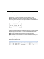
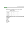
Deriving IP Parameters from the MAC Address
Introduction
If no IP parameters are received from the application when the rotary switch (see Modicon M340
for Ethernet, Communications Modules and Processors, User Manual) is set to Stored or Clear IP
positions, the module is configured at power-up with its default IP address. The default IP address
for the module is derived from its hardware MAC address in accordance with a default IP address
format.
Default IP Address Format
The default IP address format is 84.x.x.x:
84: a fixed value
x: The last three fields in the default IP address are composed of the decimal equivalents of the
last three hexadecimal bytes in the MAC address.
Example
For example, with the MAC address of 0000531201C4, you are concerned only with the last three
bytes, 12-01-C4. Convert these bytes from hexadecimal to decimal. (See the procedure below if
you don’t know how to do this.) The hexadecimal values 12, 01, and C4 have corresponding
decimal values of 18, 1, and 196, respectively. These values are combined with the default IP
address format (84.x.x.x) to yield a default IP address of 84.18.1.196.
Hexadecimal-to-Decimal Conversion
Convert the hexadecimal values in the MAC address to decimal notation to derive default IP
addresses. The easiest ways to convert values in a MAC address from hexadecimal to decimal is
with a calculator in scientific mode or through one of the many conversion charts easily accessed
on the Internet.
You can also convert hexadecimal values in MAC address to decimal values for default IP address
by following these steps:
52
Step
Action
Comment
1
Ignore the first 3 bytes of the 6-byte MAC For a MAC address of 0000531201C4, concern yourself
address.
only with the last three bytes, 12-01-C4.
2
In the most significant byte (12), multiply Subtotal = 16 (1 x 16 = 16)
the value of the leading digit (1) by 16.
3
Add the value of the second digit (2) to
the subtotal (16).
Hexadecimal value = 18 (16 + 2)
4
Convert the second byte (01) in the
same manner.
Hexadecimal value = 01 ((0 x 16 = 0) + 1 = 1)
EIO0000000505 04/2014
Ethernet Communications
Step
Action
Comment
5
In the third byte (C4), multiply leading
digit C hex (12 decimal) by 16.
Subtotal = 192 (The sequence of base-16 hexadecimal
values is 1, 2, 3, 4, 5, 6, 7, 8, 9, A, B, C, D, E, F.
Therefore, the hexadecimal value C has a decimal value
of 12.)
6
Add the second digit (4) to the subtotal
(192).
Hexadecimal value = 196 (192 + 4)
7
Add the three decimal values to the fixed Default IP address = 84.18.1.196
address value of 84.
EIO0000000505 04/2014
53
Ethernet Communications
Section 4.3
Modbus TCP/IP Messaging
Modbus TCP/IP Messaging
About this Section
This section describes the functions and characteristics of the Modbus TCP/IP profile.
What Is in This Section?
This section contains the following topics:
Topic
54
Page
Data Exchange
55
The Messaging Configuration Tab
56
Messaging Configuration Parameters
57
EIO0000000505 04/2014
Ethernet Communications
Data Exchange
Exchanges
Data exchanges take place in one of two modes:
server mode: All Modbus-over-TCP requests from the PLC are supported by the
BMX NOR 0200 H module.
client mode: This type of exchange enables Modbus-over-TCP requests to be sent using the
functions:
READ_VAR
WRITE_VAR
DATA_EXCH (see Unity Pro, Communication, Block Library)
NOTE: The maximum Ethernet frame size depends on the type of transaction. The maximum
frame size is 256 bytes for messaging.
The BMX NOR 0200 H module is used to manage these TCP connections using port 502
messaging:
servers (32 connections)
clients (16 connections)
Port 502
TCP/IP reserves specific server ports for specific applications through IANA (Internet Assigned
Numbers Authority). Modbus requests are sent to registered software port 502.
Port 502 messaging paths:
server path:
Port 502 messaging can process up to 8 incoming requests from the network. Requests are
received during the previous scan and sent to the Modbus server in the IN section.
Port 502 messaging can process up to 8 responses from the Modbus server in the IN section
(including writing the data into the socket).
client path:
Port 502 messaging can process up to 16 outgoing requests from the application in the OUT
section (including writing the data into the socket).
Port 502 messaging can process up to 16 incoming responses from the network in the IN
section. Responses are sent to the application.
EIO0000000505 04/2014
55
Ethernet Communications
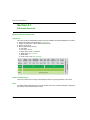
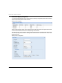
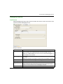
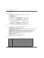
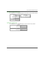
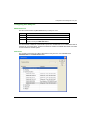
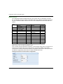
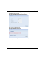
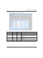
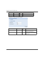
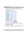
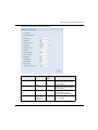
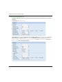
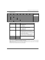
The Messaging Configuration Tab
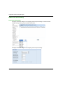
Introduction
To limit access to the BMX NOR 0200 H module, set the access control parameters on the
Messaging tab.
Messaging Tab
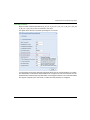
The following procedure shows how to access the Messaging page from the index page:
Step
Action
1
Access the module configuration screen.
2
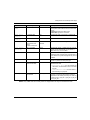
Select the Messaging tab (see illustration below).
The Messaging tab is shown below:
NOR configuration screen:
IP Configuration
Messaging
SNMP
Address Server
NTP
Connection configuration
Access
Access Control
PLC bus
IP address
1
2
3
4
5
6
7
8
9
10
11
12
Ethernet_NOR_1
The messaging configuration parameters are discussed in detail on the following pages.
56
EIO0000000505 04/2014
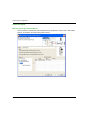
Ethernet Communications
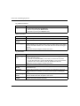
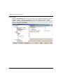
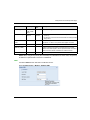
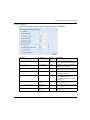
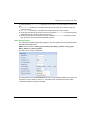
Messaging Configuration Parameters
Accessing Messaging Configuration Parameters
Configuration parameters can be accessed in two areas on the Messaging tab screen:
the Connection Configuration area
the Access Control area
Connection Configuration Area
The Connection Configuration area is used to:
activate an access control utility
list the remote devices that can connect to the module according to a communication protocol
Access Control
The Access Control box is used to activate or deactivate control of remote devices that are
attempting to open a TCP connection to the module. The functionality depends on whether the box
is checked or not:
checked: Access control management is activated and the Access column of the table is active
(no longer grayed out).
The module can only communicate to the addresses entered in the 128 available spaces in
the IP address column.
With the module in client mode it can only connect to remote devices selected by the Access
column in the Connection Configuration table.
unchecked: Access control management is inoperative and the Access column of the table is
not active (grayed out).
With the module in server mode, remote third-party devices can connect as clients (before
communicating with the module) without being declared in the table.
NOTE: Access control is only effective on the TCP/IP profile and assists module operations in
server and client mode.
NOTE: If you select the Access Control check box but do not enter addresses in the IP address
column, messaging will stop working.
EIO0000000505 04/2014
57
Ethernet Communications
Section 4.4
SNMP
SNMP
About this Section
This section describes the Simple Network Management Protocol (SNMP).
What Is in This Section?
This section contains the following topics:
Topic
58
Page
SNMP and Schneider Private MIB Overview
59
SNMP Communication
60
SNMP Operations Example
62
EIO0000000505 04/2014
Ethernet Communications
SNMP and Schneider Private MIB Overview
Introduction
An SNMP agent runs on:
Ethernet communication modules
CPUs with embedded Ethernet communications ports
Network management systems use SNMP to monitor and control Ethernet architecture
components for the rapid network diagnosis.
Network management systems allows a network manager to:
monitor and control network components
isolate troubles and find their causes
query devices, such as host computer(s), routers, switches, and bridges, to determine their
status
obtain statistics about the networks to which they are attached
NOTE: Network management systems are available from a variety of vendors. Schneider Electric
provides an SNMP-based diagnostics tool called ConneXview.
Simple Network Management Protocol
Ethernet communication modules support SNMP, the standard protocol for managing local area
networks (LANs). SNMP defines exactly how a manager communicates with an agent. SNMP
defines the format of:
requests that a manager sends to an agent
replies that the agent returns to the manager
The MIB
The set of objects that SNMP can access is known as a Management Information Base (MIB).
Ethernet monitoring and management tools use standard SNMP to access configuration and
management objects included in the device’s MIB, providing that:
objects that SNMP can access are defined and given unique names
manager and agent programs agree on the names and meanings of fetch and store operations
Transparent Ready products support two SNMP network management levels:
Standard MIB II: This first level of network management can be accessed via this interface. It
lets the manager identify the devices that create the architecture and retrieve general
information on the configuration and operation of the Ethernet TCP/IP interface.
MIB Transparent Ready interface: Schneider has obtained a private MIB, groupeschneider
(3833) (see Modicon M340 for Ethernet, Communications Modules and Processors, User
Manual). This MIB includes a set of data that enables the network management system to
supervise the Ethernet services. The Transparent Ready private MIB can be downloaded from
the Web server on any Transparent Ready module in a PLC.
EIO0000000505 04/2014
59
Ethernet Communications
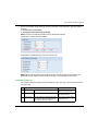
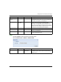
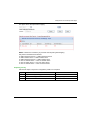
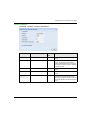
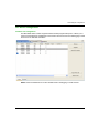
SNMP Communication
Overview
SNMP defines network management solutions in terms of network protocols and the exchange of
supervised data.
The SNMP structure relies on the following elements:
Manager: The manager allows entire or partial network supervision.
Agents: Each supervised device has one or more software modules named "Agent" that are
used by the SNMP protocol.
MIB: The Management Information Base is a database or collection of objects.
The SNMP agent is implemented on the BMX NOR 0200 H module. This allows a manager to
access MIB-II standardized objects from the Modicon M340 agent through the SNMP protocol. The
MIB-II allows management of TCP/IP communication layers.
On the modules that support Ethernet communications, it is possible to access objects from the
MIB Transparent Factory, which provides specific information about Messaging.
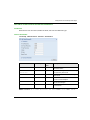
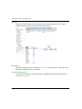
The following figure shows the tree structure of the TFE Ethernet MIB:
The source file of the TFE private MIB (see Modicon M340 for Ethernet, Communications Modules
and Processors, User Manual) is available on modules and CPUs that support Ethernet
communications. The MIB can be uploaded from the module’s web page by selecting Upload MIB
File (see page 154). This file may be compiled by the major SNMP managers on the market.
60
EIO0000000505 04/2014
Ethernet Communications
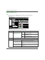
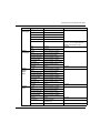
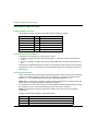
The SNMP Protocol
The SNMP protocol defines 5 types of messages between the agent and the manager. These
messages are encapsulated in UDP datagrams.
Messages from the manager to an agent:
Get_Request: message used to obtain the value of one or more variables
Get_Next_Request: obtains the value of the next variables
Set_Request : sets the value of a variable
Messages from an agent to the manager:
Get_Response: allows the agent to re-send the value of the requested variable.
Trap: allows asynchronous event signaling by the agent.
EIO0000000505 04/2014
61
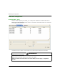
Ethernet Communications
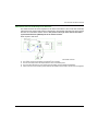
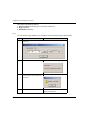
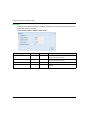
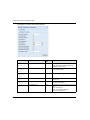
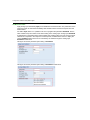
SNMP Operations Example
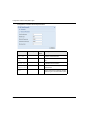
Modicon M340 Example
The SNMP manager transmits read or write requests (Set_Request, Get_Request,
Get_Next_Request, etc.) for objects defined in the MIB - II SNMP and the SNMP agent of the
Modicon M340 module responds.
1
ETHERNET
2
3
4
1
2
3
4
SNMP manager
SNMP agent (Modicon M340)
Get_Response trap
Set_Request, Get_Request, Get_Next_Request
The module’s SNMP agent transmits events (traps) to the Manager. The managed trap systems
are as follows:
Coldstart Trap:
On the BMX NOR 0200 H modules, the event is transmitted following a module supply
Reset, a processor Reset, or the downloading of an application to the PLC.
62
Authentication Failure Trap: An event is transmitted indicating that a network element
cannot be authenticated. The Community Name field in the received message is different to
the one configured on the module. This trap can be enabled during module configuration.
EIO0000000505 04/2014
Ethernet Communications
Section 4.5
SOAP Web Services
SOAP Web Services
Designing a SOAP Client Interface
Introduction
A server interface enables a SOAP (Simple Object Access Protocol) client application to
communicate directly with a BMX NOR 0200 H Web server module.
SOAP / XML Communications
SOAP Web services are fully compliant with the W3C WS-I Web services standards. These
services provide an open and standard communication means for control level devices to interact
directly with information management applications using non proprietary SOAP protocol.
Web services are based on standards such as:
SOAP, the exchange protocol carried out over the HTTP (HyperText Transfer Protocol)
channel.
WSDL (Web Services Description Language), in XML format.
XML (eXtensible Markup Language), the universal data exchange standard.
BMX NOR 0200 H SOAP Web services act as SOAP server interfaces. They allow developers to
easily design client applications that can exchange data directly with BMX NOR 0200 H Web
servers. Applications such as Microsoft.NET, SQL Server, Microsoft Office (Excel), IBM
(WebSphere), SUN (Java, Eclipse), Lotus, Oracle, SAP, MES, ERP and so forth can be interfaced
directly with BMX NOR 0200 H using SOAP Web services.
Two kinds of Web services are provided in BMX NOR 0200 H modules as SOAP server interfaces:
ModbusXMLDA: Web service to implement data access to Modbus variables,
SymbolicXMLDA: Web service to implement Symbolic data access.
The Web services provided by BMX NOR 0200 Hare compatible with the WS-I basic profile 1.1.
EIO0000000505 04/2014
63
Ethernet Communications
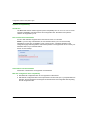
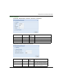
A SOAP Client Interface
The following table describes the process of designing a SOAP client interface:
Stage
64
Action
1
Create the client application:
The development environment (for example, Visual Studio.net) connects to a WEB server
module where it can access a list of available WEB services. The WEB server returns
descriptions of the requested services as WSDL objects.
2
Develop the client application:
The developer integrates the WEB service APIs using the code retrieved in the previous stage
as a WEB reference and generates the client application.
3
Execute the client application:
In run mode, the client application communicates in real time with the WEB server module using
the SOAP protocol.
EIO0000000505 04/2014
Modicon M340 RTU
Serial Communications
EIO0000000505 04/2014
Chapter 5
Serial Communications
Serial Communications
What Is in This Chapter?
This chapter contains the following topics:
Topic
Page
Serial Port
66
Serial Communication Architectures
67
EIO0000000505 04/2014
65
Serial Communications
Serial Port
Serial Communication
Serial mode is a point-to-point mode of data exchange between two entities. This provides
communication between master stations, substation devices, RTUs, and Intelligent Electronic
Devices (IEDs). It establishes client/server communication between different modules with a serial
link. The master is the client and the slave modules are the servers. The BMX NOR 0200 H serial
link module is a asynchronous serial line module that supports RTU Serial (master or slave
connections).
Serial communication using the BMX NOR 0200 H module is only possible using the RTU serial
protocols:
IEC 60870-5-101 (master or slave)
DNP3 serial (master or slave)
NOTE: The serial port is also used for the communication with an external modem (see page 69).
If a modem is connected, it is possible to perform serial RTU communication or Ethernet RTU
communication which depends on the type of modem.
66
EIO0000000505 04/2014
Serial Communications
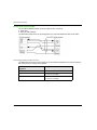
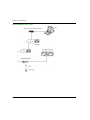
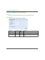
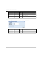
Serial Communication Architectures
General
All equipment connected via serial link to a BMX NOR 0200 H module use either:
an RS232 serial crossover cable
an RS485 serial crossover cable
Connecting Equipment
The BMX NOR 0200 H module uses serial link:
as master, in case of communication with several slaves with serial RTU protocols
as slave, when the module is directly linked with master or a supervisor (SCADA for example)
Master case:
M340 RTU (Master)
Serial
M340 RTU (slave)
Other RTU equipment
(slave)
M340 RTU (slave)
Slave case:
EIO0000000505 04/2014
67
Serial Communications
RS 232 Serial Crossover Cable
The TCS MCN 3M4F3C2 serial crossover cable has two connectors:
RJ45 male
Nine-pin SUB-D female
The illustration below shows the pin assignment for a TCS MCN 3M4F3C2 serial cross cable:
Connecting Cables and Accessories
The table below shows the product references of the cables and adapters to be used according to
the serial connector used by the equipment:
Serial Connector for Data Terminal
Equipment
68
Wiring
Nine-pin SUB-D male connector
TCS MCN 3M4F3C2 cable
25-pin SUB-D male connector
TCS MCN 3M4F3C2 cable
TSX CTC 07 adapter
25-pin SUB-D female connector
TCS MCN 3M4F3C2 cable
TSX CTC 10 adapter
EIO0000000505 04/2014
Modicon M340 RTU
Modem Communications
EIO0000000505 04/2014
Chapter 6
Modem Communications
Modem Communications
What Is in This Chapter?
This chapter contains the following topics:
Topic
Page
Modem Communication
70
Modem Support
71
Modem Register Command
73
Modem Communication Error Codes
75
Connecting External Modem (RS232)
76
How to work with External Modem
78
EIO0000000505 04/2014
69
Modem Communications
Modem Communication
Overview
The BMX NOR 0200 H module can be used with several external modem types:
Radio
PSTN
GSM
GPRS
ADSL
There are three different ways to connect an external modem to a BMX NOR 0200 H module:
via the serial port, using serial communication protocol (IEC 60870-5-101 or DNP3 serial)
via the serial port and configuring a Point-to-Point Protocol (PPP) connection, using ethernet
communication protocol (IEC 60870-5-104 or DNP3 NET)
via the ethernet port and configuring a Point-to-Point Protocol over Ethernet (PPPoE)
connection, using ethernet communication protocol (IEC 60870-5-104 or DNP3 NET)
NOTE: PPPoE connection is only used with an ADSL external modem.
70
EIO0000000505 04/2014
Modem Communications
Modem Support
Connection via Serial Link
The serial link connection can be used to configure and communicate with an external modem
(Radio/PSTN/GSM).
By default, the modem waits for an incoming call (Dial-in mode). When it receives an incoming call,
try to establish the connection.
NOTE: In the Dial-out mode, the serial link connection via modem can be created in the Permanent
mode (automatic connection at startup, at reboot or after connection loss) or in the On-demand
mode (by an internal register command).
NOTE: In the On-demand mode, Dial out is prior to Dial in. and Dial out may interrupt established
connection in Dial in mode.
Connection Point-to-Point Protocol via Serial Link
The BMX NOR 0200 H module supports PPP connections over serial links via a modem
(PSTN/GSM/GPRS).
With a PPP connection, once a telephone connection has been established, the modem link is
treated as a TCP/IP link.
A PPP connection enables two specific modes:
Server mode, which is the Dial-in mode
Client mode, which is the Dial-out mode.
NOTE: In the Client mode, the PPP connection via modem can be created in the Permanent mode
(automatic connection at startup, at reboot or after connection loss) or in the On-demand mode (by
an internal register command).
NOTE: For PPP connection authentication, the identification uses the Password Authentication
Protocol (PAP). Use PAP to configure any device that has a modem/PPP connection with the
BMX NOR 0200 H module. The Challenge Handshake Authentication Protocol (CHAP) is not
implemented on the module. For an accepted connection, the PAP Username and Password of
the remote device must be known. The BMX NOR 0200 H module password and user name used
by the PAP protocol are the same as those of the HTTP server (by default: USER/USER).
The local IP address of the BMX NOR 0200 H module can be configured using the IP address
either:
specified by the User directly from the website. This is mandatory if the module is in Server
mode.
obtained from the PPP server (if specifying 0.0.0.0 as local IP) when establishing connection in
Client mode. The IP can then be a static or a dynamic address.
NOTE: In Server mode and no IP address is given by the User, the Server assigns a fixed IP to
the remote device with local IP+1. For example if the server IP is 90.0.0.2, remote device IP is then
90.0.0.3.
NOTE: GPRS does not support server mode.
EIO0000000505 04/2014
71
Modem Communications
Connection PPPoe via Ethernet Link
The Ethernet link connection can be used to configure and communicate with an external modem
(type ADSL).
PPPoe connection is only available using Client mode (Server mode not supported).
NOTE: In the Client mode, the PPPoe connection via modem can be created in the Permanent
mode (automatic connection at startup, at reboot or after connection loss) or in the On-demand
mode (by an internal register command).
NOTE: For PPPoe connection authentication, the identification uses the Password Authentication
Protocol (PAP). Use PAP to configure any device that has a modem/PPPoe connection with the
BMX NOR 0200 H module. The Challenge Handshake Authentication Protocol (CHAP) is not
implemented on the module. For an accepted connection, the PAP Username and Password of
the remote device may be configured in PPPoe panel from the website.
The configuration of IP address is not available for users. The BMX NOR 0200 H module obtains
a static or dynamic IP address when the PPPoe connection is established.
72
EIO0000000505 04/2014
Modem Communications
Modem Register Command
Introduction
Modem register commands are specified memory area allocated on the M340 CPU. This memory
area is used to send commands from CPU to the BMX NOR 0200 H module via the M340 rack to
control the connection or disconnection of the modem using logic functions.
Register Command
The commands are composed of 4 registers (%MW):
Register
number
Parameter
Definition
Value
0
Command
Logic function to establish/close 1: connect
a connection.
2...65535: disconnect
Disconnect command takes
effect if it changes between 2
and 65535.
1
Index
Value in phone list in which are
set telephone number, IP,
password and user name - not
used for GPRS and PPPoE.
range from 1...64
2
Command status
Execution status of Reg 0
command while establishing a
connection.
3
Connection status
Status of the connection.
0: closed
1: open
0000 hex: idle
0001 hex: on going
0002 hex: OK
8001 hex: detected error - Invalid phone index
8002 hex: detected error - unable to initialize
8003 hex: detected error - unable to dial-out
8004 hex: detected error - unable to make a
PPP connection
NOTE: The command register are exchanged via the M340 rack, then the performances are
dependent on PLC scan period, the workload of the RTU protocol and the number of
BMX NOR 0200 H module plugs in the rack.
For PPP/Modem and PPPoE Link, another 4 registers (%MW) following above registers are used
to show local IP and remote IP address:
Register number
Parameter
Definition
4/5
Local IP
IP address is stored as MSB.
6/7
Remote IP
IP address is stored as MSB.
For example: %MW100 = 0A0B hex, %MW101= 0C0D hex, which means this IP is "10.11.12.13".
EIO0000000505 04/2014
73
Modem Communications
Example for modem register:
Register 3
Register 2
Reg 1
Reg 0
Connection
status
Command status
Index
Command
0
0000 hex
0
0
0001 hex (on going)
1
1
0002 hex (command OK)
1
1
0
0001 hex (on going)
1
1
0
8001 hex/8002 hex/8003 hex/8004 hex
1
1
1
0001 hex (on going)
1
2
0
0002 hex (command OK)
1
2
0
0000 hex (idle)
1
2
1
0001 hex (on going)
1
2
0
8001 hex/8002 hex
1
2
1
0001 hex (on going)
1
3
0
0002 hex (command OK)
1
3
0
0000 hex (idle)
1
3
1
0001 hex (on going)
1
3
0
8001 hex/8002 hex
1
3
74
Comment
Case
0
original
–
1
connect (dial-out)
OK
connect (dial-out)
NOK
disconnect (hang up)
OK
disconnect (hang up)
NOK
disconnect (repeat hang up)
OK
disconnect (repeat hang)
NOK
EIO0000000505 04/2014
Modem Communications
Modem Communication Error Codes
Introduction
In order to diagnose modem, error codes are available in Modem Diagnostic Web page.
Error Codes
The table below describes the modem communication error codes:
Value
Bit
Definition
00000100 hex
8
The phone index is not available in your phone list.
00000200 hex
9
PPP is not enabled when PSTN/GSM/GPRS modem is set.
EIO0000000505 04/2014
75
Modem Communications
Connecting External Modem (RS232)
General
For an external modem, the RTS and CTS pins are connected directly (not crossed).
External modems are connected to a BMX NOR 0200 H module by a serial direct cable using an
RS232 physical link. BMX NOR 0200 H module works with many commercially available modems.
Application
The illustration below shows how a modem is connected to a slave BMX NOR 0200 H module
configured with PPP:
NOTE: In case of a PPPoE configuration, connect the modem on the Ethernet port of the
BMX NOR 0200 H module.
76
EIO0000000505 04/2014
Modem Communications
RS 232 Serial Direct Cable
The TCS MCN 3M4M3S2 serial direct cable has two connectors:
RJ45 male,
Nine-pin SUB-D male.
The illustration below shows the pin assignment for a TCS MCN 3M4M3S2 serial direct cable:
Connecting Cables and Accessories
The table below shows the product references of the cables and adapters to be used according to
the serial connector used by the external modem:
Serial Connector for Data Circuitterminating Equipment
Wiring
Nine-pin SUB-D female connector
TCS MCN 3M4M3S2 cable
25-pin SUB-D female connector
TCS MCN 3M4M3S2 cable
TSX CTC 09 adapter
EIO0000000505 04/2014
77
Modem Communications
How to work with External Modem
Connection/Disconnection
After an external modem has been connected to a BMX NOR 0200 H module, use the website to
configure the module.
The main feature of the modem is the possibility to work in Permanent mode or in On-Demand
mode:
Permanent mode: the connection is automatically performed when the BMX NOR 0200 H
module is on power.
On-Demand mode: the connection or disconnection is performed depending on the command
register (see page 73).
Use the website to set a serial PPP connection.
NOTE: Do not forget to configure the serial port via the Website when the external modem is
connected to it.
NOTE: GPRS MODEM does not support server mode.
Dialing
In practice, the Dial-in/Dial-out depends of the module mode. There are two different cases:
The module is in Server/Slave mode: the modem connected to the module is in Dial-in mode.
The module is in Client/Master mode: the modem connected to the module is in Dial-out mode.
Radio Modem User Cases
78
EIO0000000505 04/2014
Modem Communications
PSTN Modem User Cases
EIO0000000505 04/2014
79
Modem Communications
GPRS/GSM Modem User Cases
80
EIO0000000505 04/2014
Modem Communications
ADSL Modem User Cases
EIO0000000505 04/2014
81
Modem Communications
82
EIO0000000505 04/2014
Modicon M340 RTU
Functional Description
EIO0000000505 04/2014
Part IV
Functional Description
Functional Description
Introduction
This part describes the functionality of the BMX NOR 0200 H module.
What Is in This Part?
This part contains the following chapters:
Chapter
Chapter Name
Page
7
How to Work with RTU Protocols
8
How to Work with Datalogging Service
115
9
How to Work with Email/SMS Service
127
How to Work with Embedded Web Pages
137
10
EIO0000000505 04/2014
85
83
Functional Description
84
EIO0000000505 04/2014
Modicon M340 RTU
How to Work with RTU Protocols
EIO0000000505 04/2014
Chapter 7
How to Work with RTU Protocols
How to Work with RTU Protocols
Introduction
This chapter describes the built-in RTU protocols characteristics for use in Telemetry and
Supervisory Control and Data Acquisition (SCADA) applications.
What Is in This Chapter?
This chapter contains the following sections:
Section
Topic
Page
7.1
RTU Protocols
86
7.2
Clock Synchronization
92
7.3
Time Stamping
97
7.4
Events Management
7.5
Integrity Poll Command
109
7.6
Transmission Modes
112
7.7
Connection Status
113
7.8
Communication Error Codes
114
EIO0000000505 04/2014
98
85
How to Work with RTU Protocols
Section 7.1
RTU Protocols
RTU Protocols
What Is in This Section?
This section contains the following topics:
Topic
86
Page
Communication Protocols
87
IEC 60870-5-101/104 Protocols Overview
88
DNP3 Protocols Overview
90
EIO0000000505 04/2014
How to Work with RTU Protocols
Communication Protocols
Introduction
This topic describes the characteristics of the supported RTU protocols.
Functions and Protocols
The BMX NOR 0200 H module supports these functions and protocols:
RTU protocols
IEC 60870-5-101 (master or slave)
IEC 60870-5-104 (client or server)
DNP3 serial (master or slave)
DNP3 NET (client or server)
Main RTU Protocol
Features
time synchronization through a protocol facility or NTP
balanced and unbalanced transmission mode
events management with time stamping
events queue stored in RAM memory (up to 100,000 events for all clients)
events data backfill to SCADA application via protocol facility
report by exception data exchanges
unsolicited messaging data exchanges
protocol setup via Web page
NOTE: The RTU protocol parameters are configured using the embedded Web pages.
Limitations
The BMX NOR 0200 H module does not support multiple RTU protocols instances. Only one
instance at a time of an RTU protocol (IEC, DNP3) can be launched to work with Modbus TCP.
WARNING
UNINTENDED EQUIPMENT OPERATION
Use different address values for each session in a channel or for each section in a session.
Channel parameters must meet IEC60870-5-104 protocol requirements with these limitations:
T2 S Frame Period < T1 Ack Period and W Value < 2/3 K Value.
If you are using the DNP3 protocol, use successive DB mapping starting at 0.
Failure to follow these instructions can result in death, serious injury, or equipment
damage.
EIO0000000505 04/2014
87
How to Work with RTU Protocols
IEC 60870-5-101/104 Protocols Overview
Introduction
IEC 60870-5 is an international standard released in the early 1990s by the International
Electrotechnical Commission (IEC). This standard provides a communication profile for telecontrol,
teleprotection, and associated telecommunications characteristics for electric power systems. It is
widely used today for other infrastructures, including water applications in Europe and Asia.
The IEC 60870-5-101 and IEC 60870-5-104 protocols are companions to the IEC 60870-5
standards that relate to transmission protocols.
IEC 60870-5-101
The IEC 60870-5-101 protocol is based on the EPA (Enhanced Performance Architecture). This
protocol defines only the physical link and application layers of the OSI model. IEC 60870-5-101
is used primarily on serial links with relatively slow transmission media. This standard conforms to
baud rates of up to 9600 bit/s, although much higher baud rates (<115200 bit/s) are being used.
IEC 60870-5-104
The IEC 60870-5-104 protocol is an extension of the IEC 60870-5-101 protocol. There are
changes in transport, network, link & physical layer to open networking.
IEC 60870-5-104 enables communication between control stations and substations in a standard
TCP/IP network. The TCP protocol is used for connection-oriented data transmission. To have
connectivity to LANs and routers with different facilities (frame relay, etc.), connect it to the WAN.
The application layer of IEC 104 is the same as that of IEC 60870-5-101, except that some data
types and facilities are not used. There are separate link layers defined in the standard, which
facilitates the transfer of data over Ethernet and serial lines.
Supported Protocol Features
Features of the IEC 60870-5-101/104 protocols:
general interrogation
clock synchronization
events transmission (time-stamped or not)
balanced and unbalanced communications
counter interrogation
command transmission modes (select and execute mode)
Supported Data Types
The IEC 60870-5-101/104 protocols include these data types:
discrete inputs/outputs (single or double)
measured values (with different formats)
integrated totals
commands
88
EIO0000000505 04/2014
How to Work with RTU Protocols
Protocol Characteristics
The table lists the characteristics for the supported RTU protocols:
Protocol
Characteristics
IEC 60870-5-101 master
up to 32 slaves (1 session for each slave and up to 5 sectors per session),
individual database definition for each sector
IEC 60870-5-101 slave
up to 5000- point database for data objects of all supported types
up to 5000-point database for all sectors including predefined commands
up to 100,000-event queue for all data types
supports clock synchronization from a master, CPU or NTP
configurable data link address CAA (Common ASDU Address) and IOA
event time-stamping configurable by type (None, CP24, CP56)
IEC 60870-5-104 server
client IP address validation list (up to 10 IP addresses)
up to 4 concurrent client connections with configurable TCP service port
(standard is 2404)
up to 5000-point database for data objects of all supported types
up to 100,000-event queue for all data types in all clients (each client has
a dedicated event buffer)
event time-stamping configurable by type (None, CP56)
configurable CAA (common ASDU address) and IOA
IEC 60870-5-104 client
up to 5000-point database for all sectors including predefined commands
up to 64 servers connections supported
connections share common channel configuration
dedicated connection for each session and sector configuration
dedicated destination IP address and port settings for each connection
Interoperability Lists
The interoperability list (defined by the standard) facilitates interoperability between devices from
different manufacturers. In the list, the function range is described for each device by marking the
applicable functions.
NOTE: You can find BMX NOR 0200 H IEC interoperability list in Appendices. (see page 306)
EIO0000000505 04/2014
89
How to Work with RTU Protocols
DNP3 Protocols Overview
Introduction
The distributed network protocol (DNP3) protocol was developed to achieve an open, standard
interoperability for communications between master stations, substation devices, RTUs, and
Intelligent Electronic Devices (IEDs). DNP3 has been used primarily by utilities such as the electric
power industry in North America and has become widely used in other distributed infrastructures
such as water/wastewater, transportation and oil and gas industries.
DNP3 is based on the International Electrotechnical Commission Technical Committee 57
Working Group 03. The IEC TC57 WG03 has been working on the Enhanced Performance
Architecture (EPA), a protocol standard for telecontrol applications. Each of the EPA’s 3 layers
corresponds to a layer on the OSI reference model.
DNP3 is specifically developed for inter-device communications that use SCADA RTUs. The
protocol facilitates both RTU-to-IED (Intelligent Electronic Device) and master-to-RTU/IED.
The protocol was originally designed for slow serial communications, but the current DNP3 IP
version also supports TCP/IP-based networking.
Supported Protocol Features
These are the main features that DNP3 supports:
clock synchronization
polled interrogations
polled report-by-exception
unsolicited report-by-exception
events transmission (time-stamped or not)
counter-specific treatment
master commands
Supported Data Types
The DNP3 protocol includes these data types:
discrete inputs/outputs (single or double)
measured values (with different formats)
integrated totals
commands
90
EIO0000000505 04/2014
How to Work with RTU Protocols
Protocol Characteristics
The table lists the characteristics for the supported RTU protocols:
Protocol
DNP3 master/DNP3 NET client
Characteristics
up to 32 slaves/servers (1 session for each slave/server)
up to 5000-point database for slaves data objects including predefined
commands
DNP3 slave/DNP3 NET server
up to 5000-point database for data type objects
up to 100,000-event queue for all data types
supports clock synchronization from a master
service over
TCP
client IP address validation list (up to 10 IP addresses)
4 concurrent client connections with configurable TCP
service port (default port is 20000)
Interoperability Lists
This implementation of DNP3 is fully compliant with DNP3 Subset Definition Level 3, which suits
larger RTU applications and offers practically the complete range of DNP3 functionality.
This standard defines interoperability between devices from different vendors. It includes a device
profile that describes the basic protocol functionalities supported by the device and an Implementation table that defines information objects and their representation supported by the device.
EIO0000000505 04/2014
91
How to Work with RTU Protocols
Section 7.2
Clock Synchronization
Clock Synchronization
Overview
The BMX NOR 0200 H module provides 2 ways to synchronize the clock with the SCADA (master)
and the connected devices:
via the RTU protocol facilities
via the NTP protocol
NOTE: These clock synchronization methods are independent of one another. Configure your
application to avoid clock synchronization conflicts.
The clock synchronization service establishes time accuracy among devices clocks over a
network.
What Is in This Section?
This section contains the following topics:
Topic
92
Page
Clock Synchronization with the RTU Protocol Facilities
93
Clock Synchronization with the NTP Protocol
94
EIO0000000505 04/2014
How to Work with RTU Protocols
Clock Synchronization with the RTU Protocol Facilities
Overview
One of the main feature of the RTU is to manage events with time stamping. Time stamping
requires effective time synchronization.
Slave/Server
When acting as an IEC 60870-5-101/104 or DNP3 slave or server, the BMX NOR 0200 H module
can synchronize its clock with a master or client station (SCADA). When the module receives the
clock synchronization command, it updates its internal clock and posts the new value to the M340
CPU. This maintains a consistent time on the local rack.
Master/Client
When acting as an IEC 60870-5-101/104 or DNP3 master or client, the BMX NOR 0200 H module
sends clock synchronization commands to connected slaves. As with the case above, the clock is
initialized from the CPU when it starts up. It will get new time from CPU every time master/client
send time synchronization command.
Slave/Server and Master/Client
When acting as both a master/client or slave/server, the BMX NOR 0200 H module periodically
synchronizes its local time with that of the M340 CPU through the rack.
EIO0000000505 04/2014
93
How to Work with RTU Protocols
Clock Synchronization with the NTP Protocol
Features of the Service
The clock synchronization via NTP offers:
periodic time corrections obtained from the reference standard, for example, the NTP server
automatic switchover to a backup time server if a trouble occurs with the normal server system
local time zone configurable and customizable (including daylight saving time adjustments)
Controller projects use a function block to read the clock, a feature that allows events or variables
in the project to be time stamped. Time stamping is accurate to:
5 ms typical
10 ms worst case
Clock Synchronization and Time Stamps
The BMX NOR 0200 H module sends a source clock synchronization signal to a M340 CPU. The
module firmware includes an NTP client, which provides clock synchronization. The synchronization process occurs as follows:
The NTP Client...
Result
1
... requests a clock synchronization
signal from the NTP server over an
Ethernet network.
The NTP server sends a signal.
2
... stores the time.
3
... sends a message to the clock system
counter in the CPU.
The CPU updates its internal clock. The
CPU’s clock is now typically within 5 ms
of the NTP server, with a worst case of
10 ms.
Before the next clock synchronization
signal, the CPU’s clock is updated each
ms by an internal timer.
Use the R_NTPC function block (see Modicon M340 for Ethernet, Communications Modules and
Processors, User Manual) in either MAST, FAST, or Interrupt sections to read the clock from the
PLC application.
94
EIO0000000505 04/2014
How to Work with RTU Protocols
The CPUs on an Ethernet network should be synchronized with the same NTP server.
CPS
CPU
NO R
Clock
System
Counter
NTP Request
NTP
Client
R_NTPC
EN0
EN
NTP
Server
Ethernet
Network
NTP Response
M340 System
OUT1
OUT2
STATUS
Clock Synchronization Terms
Term
Description of Service
local clock offset
Accurate local time adjustments are made via a local clock offset. The local clock offset
is calculated as:
((T2 - T1) + (T4 - T3))/2
where:
T1 = time when NTP request is transmitted from the module
T2 = time when NTP server receives the request (provided by the module in response)
T3 = time when the NTP server transmits the response (provided to the module in the
response)
T4 = time when NTP response is received by the module
time accuracy
The local time margin is < 10 ms compared to the referenced NTP server’s time.
typical: 5 ms
worst case: <10 ms
settling time
Maximum accuracy is obtained after 2 updates from the NTP server.
polling period
dependency
Accuracy depends on the polling period. Less than 10 ms of margin is achieved for polling
periods of 120 ms or less. To obtain a high degree of accuracy (when your network
bandwidth allows), reduce the polling period to a small value—e.g., a polling time of 5 s
provides better accuracy than a time of 30 s.
time zone
The default format is universal time, coordinated (UTC). Optionally you may configure the
service to use a local time zone—e.g., GMT+1 for Barcelona or Paris
daylight saving
time
The module automatically adjusts the time change in the spring and fall.
leap second
To compensate for the deceleration of the earth’s rotation, the module automatically
inserts a leap second in the UTC time every 18 months via an international earth rotation
service (IERS).
Leap seconds are inserted automatically as needed. When needed, they are inserted at
the end of the last minute in June or December, as commanded by the NTP server.
EIO0000000505 04/2014
95
How to Work with RTU Protocols
Obtaining and Maintaining Accuracy
The time service clock starts at 0 and increments until the Ethernet network time is fully updated
from the module.
Model
Starting Date
M340 with Unity Pro
January 1, 1980 00:00:00.00
Clock characteristics:
Clock accuracy is not affected by issuing stop/run commands on the PLC
Clock updates are not affected by issuing stop/run commands on the PLC
Mode transitions do not affect the accuracy of the Ethernet network
Re initializing the Time Service Register
After a download or an NTP server swap, the status clock value associated with the time service
register in the CPU is re initialized.
Two polling periods elapse before an accurate time is reestablished.
96
EIO0000000505 04/2014
How to Work with RTU Protocols
Section 7.3
Time Stamping
Time Stamping
Event Time Stamping
Overview
BMX NOR 0200 H module provides two ways for time stamping of events:
Time stamping done at source in the M340 CPU (requires PLC programming).
Time stamping done in the RTU module (no PLC programming required).
NOTE: Improved time stamping resolution can be obtained when performing the time stamping in
the PLC CPU. Time stamping resolution is basically depending on the CPU scan time and I/O
modules type.
Supported Time Formats
In IEC 101 the Time Format for events time stamping may be set to one of the following options:
CP56: 56-bit (default)
CP24: 24-bit
The 56-bit Time Format is an absolute time format, whereas the 24-bit Time Format is an
incremental time format that only specifies minutes and milliseconds. The IEC 104 protocol uses
56-bit time format.
EIO0000000505 04/2014
97
How to Work with RTU Protocols
Section 7.4
Events Management
Events Management
What Is in This Section?
This section contains the following topics:
Topic
Overview
98
Page
99
Events Routing
101
Events Backup
106
EIO0000000505 04/2014
How to Work with RTU Protocols
Overview
Introduction
The BMX NOR 0200 H module generates events on changes of state, handles events lists and
provides the following services:
The management of a buffer of events (time stamped or not), overall buffer (queue) size can be
up to 100,000 events (the maximum value is 100,000 from RTU 1.5).
NOTE: One dedicated event buffer is managed per client/master application (up to 4 client/master
applications are supported).
Automatic event backfill to the SCADA or the master station via RTU protocol facility (on DNP3
and IEC 101/104).
For RTU slave configuration (DNP3 slave, IEC 60870-5-101 slave and IEC 60870-5-104 server),
each object type has an independent event queue setting. To generate an event, set an event
queue for the corresponding object type.
Event Generation
A dialog box is used to configure the event generation:
Object Group
Point Count
EIO0000000505 04/2014
99
How to Work with RTU Protocols
Event Queue Setting Page
The user can map event queue status to CPU registers. The status for each event queue is a 32bit register (2 words in CPU). A higher word 1 means the event queue has overflowed. The lower
word is the number of events in the event queue.
From the Web site, select event mapping:
NOTE: When the events number exceeds the configured buffer size, events will be lost or
overwritten.
Increasing Maximal Event Buffer Size
You can increase the maximum events buffer size from 10,000 to 100,000 (in case of one client
connection).
NOTE: All channels can support up to 100,000 events, but each point type only supports up to
65,535 events.
A dialog box is used to configure the maximum event count:
100
EIO0000000505 04/2014
How to Work with RTU Protocols
Events Routing
Introduction
The events routing component allows events from sub stations to be routed to SCADA within one
BMX NOR 0200 H module.
To route events, one RTU master channel and at least one RTU slave channel are needed inside
the M340 system. The solution is to create a logic RTU master and slave in a single
BMX NOR 0200 H module. In the logic master, points are created to represent points in sub
stations, and in the logic slave, points are created to simulate the behavior of points in sub stations.
Events routing component is responsible for collecting events in the logic master. These events
are sent from sub stations, and trigger the same events in the logic slave.
BMX NOR 0200 H module components:
Configuration
Configure the BMX NOR 0200 H module for event routing. Most of the BMX NOR 0200 H module
parameters are configured via Web pages as are the event routing functions. There is no dedicated
Web page for the events routing function, this function is configured inside the data mapping
configuration pages.
NOTE: The BMX NOR 0200 H does not detect events for the routing points in slave.
NOTE: With the loss of power management, you can specify in the configuration whether or not
you want to poll more events from the BMX NOR 0200 H modules, fallback to SCADA and prevent
events from being lost.
Channel Configuration
For routing events, configure one master channel and at least one slave channel. One master
channel is required so that the system can connect with more sub slaves, and more slave channels
allow for more SCADA in the system.
EIO0000000505 04/2014
101
How to Work with RTU Protocols
Master Data Mapping Configuration
You must first add data points in the master channel. These points represent points in the sub slave
which communicate with the master channel.
Master points mapping:
When configuring these points in the master channel, select the events of the point which needs
to be routed, and route events to the corresponding slave channel.
For example, if the master channel needs to receives events needs to receive events from the sub
slave Binary Input point, routed it to the logic slave channel and so that becomes an event of the
Binary Input point.
Master points configuration:
102
EIO0000000505 04/2014
How to Work with RTU Protocols
NOTE:
When the user specifies one point in the master for event routing such as the binary input point,
one corresponding point configuration is automatically generated in the logic slave channel. The
point configuration is read only in the logic slave channel, and cannot be changed or removed
in its DB mapping panel.
If the channel number, session number, or point number mismatches in the slave channel, an
error page appears.
If the user chooses the route to the channel as None, this means that this point does not need
to be routed to a slave.
Slave Points Configuration
After configuring the points in the master channel, the corresponding point is listed in the slave
channel.
Slave points mapping:
The points used to route are different from the normal points of the slave. The parameters (CPU
type, CPU address, variable name, and time stamp) of CPU mapping are no longer available, and
the available parameters are read only. Their lifetime is consistent with peer point
configuration in the master.
EIO0000000505 04/2014
103
How to Work with RTU Protocols
Slave points configuration:
Channel Combination for Events Routing
To route events inside the BMX NOR 0200 H module, follow the configuration instructions
(see page 101) to combine the master channel and slave channel.
The supported combinations are:
Master channel
104
Slave channel
DNP3 net client
DNP3 net server
DNP3 serial master
DNP3 net server
IEC-104 client
IEC-101 master
IEC-104 server
IEC-104 server
EIO0000000505 04/2014
How to Work with RTU Protocols
Limitations
Events are routed inside the module. This means that it is not possible to route events between
two or more modules and also that the PLC application in the CPU cannot get and process the
events (the CPU can still get the point value in events just like the standalone master channel).
Events and static points are routed. Requests (commands) from SCADA are not routed to the
sub slave. This means that inside the BMX NOR 0200 H module, there is no other data
exchange or communication between the master channel and the slave channel except for
events.
Not all master and slave channel combinations are supported by the routing function
(see page 101).
In the system, SCADA cannot communicate with sub slaves. The solution uses the logic slave
in the BMX NOR 0200 H module to simulate sub slaves, so SCADA can only communicate with
the logic the slave in the BMX NOR 0200 H module, and sub slave can only communication with
the logic master in BMX NOR 0200 H module.
Some information related to events may be changed. Key information related to events like point
value, flag, and timestamp is kept during routing. Other information related to events like point
number, events class, and variation is changed according to the slave channel configuration.
Events Buffer Size
The events buffer of the slave must be greater than the events buffer in the sub slave otherwise
events are lost.
EIO0000000505 04/2014
105
How to Work with RTU Protocols
Events Backup
Introduction
The BMX NOR 0200 H and RTU protocol have a maximal number of events buffer size of 100,000.
NOTE: The BMX NOR 0200 H module supports the backup of up to 10,000 events into Flash
memory on loss of power. Only the latest events are saved if the number of events is more than
10,000.
The event monitor component:
saves up to 10,000 events into Flash memory on loss of power,
reads events from the Flash memory when power is restored,
saves only the latest events if the size of the saved events exceeds 10,000,
can be configured to decide which events or data types need to be saved on loss of power.
Web Configuration
Event backup is a configurable feature for users. It can be enabled or disabled on the Web site as
shown in the picture below and it is disabled by default. This feature is set individually for each
channel and each data type. Only the events of the main channel are saved on loss of power. After
power restoration, the saved events can be restored into the main channel, and also the virtual
channels, which depend on Event Restore Mode configuration in the Web site. These
configurations take effect after a communication reset in the Web site or power recycle.
Configuration of event backup:
Event restore mode:
Event backup enable: Specifies whether the channel (IEC or DNP3 server/slave) supports
event backup if the module does not power up. It is only effective for the main channel.
Event restore mode: It has two options, main channel and all channels. Select the main
channel option if you want to add saved events into the event buffer of the main channel when
power restores, ignoring the virtual channel. Select the option all channels if you want to add
saved events into both the main channel and virtual channels when power restores.
106
EIO0000000505 04/2014
How to Work with RTU Protocols
Events Time Quality: When restoring backup events after power restoration, the time quality is
forced to
invalid with Forcing Invalid
the original quality with Original Quality
NOTE: The box Event Backup Enable must be checked beforehand.
Configuration of event backup for DNP3:
Configuration of event backup for IEC 101 and IEC 104:
NOTE: When restoring events from the Flash into the event buffer after power restores, the
BMX NOR 0200 H module sorts the events according to the timestamps of the events.
Event Backup Behavior
The RTU has different backup behaviors in different cases. The type of case is defined from the
user point view:
Case
Event
1
Loss of power power lost
Saves events in non volatile
memory on loss of power
2
Power start
power on/restore
Restores events when the
RTU protocol starts
3
Protocol exit
Unity Pro Ethernet configuration resets
RTU communication through Web site
RTU protocol cold/warm restart.
Does not save events when
the protocol exits
EIO0000000505 04/2014
107
How to Work with RTU Protocols
Signature Authentication
Signature authentication is required when events are restored from the Flash memory. It checks if
the protocol configuration has changed during the power loss and restore. If the signature of the
XML configuration is different from the record in the Flash, all the events are deleted directly.
NOTE: The signature changes if the parameters of the channel/session/sector or Network
Type/IP/Port/Start Reg Addr/Connection Count have changed. The Modem/PPPoE/Serial
Port/Time Zone do not have an effect on the signature.
Limitations
If the events number to save exceeds the size of the Flash memory, the BMX NOR 0200 H module
saves only the latest events.
108
EIO0000000505 04/2014
How to Work with RTU Protocols
Section 7.5
Integrity Poll Command
Integrity Poll Command
Integrity Poll Command
Introduction
Command DNP3 and Integrity Poll: Integrity poll retrieves all event (class 123) and static (Class
0) data from the device. It is typically sent after device restart, loss of communication, or on a
periodic basis to check data accuracy.
Command IEC and General Interrogation: The General Interrogation command retrieves all or
a specified group of static data. It is typically sent after device restart, loss of communication, or on
a periodic basis so that no changes are missed in the spontaneous data reporting.
Communication Behavior
The BMX NOR 0200 H module has three communication ports, one serial port, one ethernet port,
and a BMX M340 backplane interface.
The serial port and the ethernet port are mainly used to communicate with the remote master or
slaves with RTU protocols. The backplane interface is used to communicate with the M340 CPU.
The main activity of the backplane interface is synchronizing data between CPU registers and the
RTU point database inside the module. The synchronization cycle can be one or more M340 PLC
application scan cycles, depending on the data amount and backplane load.
EIO0000000505 04/2014
109
How to Work with RTU Protocols
When Master Channel Receives Events from Sub Slave
When something significant changes in sub slave, such as a value of a point, the sub slave sent
out an event. The M340 system receives this event and the event needs to be routed to SCADA
system.
Events routing:
1
2
3
4
Sub slave sends out events to the master channel.
Master channel updates the point values in the module and the database of the logic slave channel and
synchronizes the value to CPU registers.
Events are routed to slave channels according to point configuration.
Slave channel buffers these events and sends events to SCADA if communication link is established.
When Slave Channel Receives Request from SCADA
In the RTU system, SCADA sends requests (commands) like an Integrity Poll to slaves connected
to it. The slave channel receives this request and sends a response to SCADA. In the routing
system, the behavior of the slave channel is exactly the same as a standalone (without events
routing) slave channel. the master channel and sub slaves are not involved in this case.
Response to the request from SCADA:
1
2
3
110
SCADA sends an Integrity Poll request to the slave channel.
Points values are synchronized cyclically between the database of the slave channel and CPU registers.
The slave channel responds to the SCADA request with the points value in the database.
EIO0000000505 04/2014
How to Work with RTU Protocols
When Master Channel Sends Request to Sub Slave
The master channel can send requests to a sub slave connected to it, and a sub slave sends the
response back to as the master channel. The behavior of the master channel in this case is exactly
the same as a standalone master channel. The points in the logic slave channel should be
synchronized with the updated point in the master channel.
Send request to sub slave:
1
2
3
4
5
PLC application in the M340 CPU sends a Integrity Poll command to the master channel.
The master channel send Integrity Poll request to the sub slave.
The sub slave responds to the request with the value of the latest points.
The logic slave data base is synchronized while the master channel updates the database.
Points value are synchronized cyclically between the database of the master channel and CPU registers.
EIO0000000505 04/2014
111
How to Work with RTU Protocols
Section 7.6
Transmission Modes
Transmission Modes
Overview
Introduction
With DNP3 or IEC101/104 protocols, the BMX NOR 0200 H module manages different ways of
retrieving data with the following transmission modes:
balanced or unbalanced transmissions
polled interrogations
report by exception
unsolicited messaging
mix of the above methods
NOTE: For transmission modes setup, set the Advanced Parameters (see page 253) (DNP3).
Balanced and Unbalanced Mode
In the unbalanced transmission mode only the master station can initiate data transfer with the
remote devices by polling the slaves. In balanced transmission mode, both the master and slaves
can initiate data transfer.
Polled Interrogations
Polled Interrogations is the basic data exchange method. The master station requests data to
multiple RTU station devices by polling periodically the remote slaves.
Report by Exception
Report By Exception (RBE) provides optimized data transfer between master and slaves stations,
where only changes of data are reported, whereas in Polled Interrogations - the master station
periodically requests data to the slaves devices. RBE is particularly useful when using low rate
communication media (PSTN, GSM/GPRS) by reducing traffic overhead and transmission costs.
Unsolicited Messaging
Unsolicited Messaging is the basic data exchange method. The slave station initiates data
transmission even though the master station does not send poll interrogations.
112
EIO0000000505 04/2014
How to Work with RTU Protocols
Section 7.7
Connection Status
Connection Status
Overview
Introduction
The connection status of each channel of the module is put in a double-word descriptor that is
mapped to the M340 CPU’s memory of your PLC program facility.
Word Mapping
You assign a valid M340 CPU memory address to which the connection status descriptor is to be
mapped.
NOTE: For IEC 60870-5-104 and DNP3 server witch configured to connect with more than one
client, each client has an independent connection status, and they store in sequence in CPU
memory.
The descriptor occupies 2 consecutive M340 CPU memory words. The following tables show the
information that the connection status descriptor contains.
Bit 31
Bit 30...Bit 1
Session #31 session #30...session #1
Bit 0
session #0
For the IEC 60870-5-101in balanced mode and the DNP protocol, the connection status
descriptors are set to 1 to indicate that all slaves are connected. Then the corresponding bit is reset
to 0 after the command is sent without the reception of a valid response.
NOTE: If connection status really matters, configure parameter "Test Frame Period" with a none
zero value for IEC 60870-5-101 protocol, "Link Status Period" for DNP3 protocol
EIO0000000505 04/2014
113
How to Work with RTU Protocols
Section 7.8
Communication Error Codes
Communication Error Codes
RTU Protocols Communication Error Codes
Introduction
In order to diagnose RTU communication, error codes are available in RTU diagnostic Web page.
Error Codes
The table below describes the RTU protocols communication error codes:
114
Value
Definition
00000001 hex
Total count of data points in all channels exceeds 5000.
00000002 hex
Total count of data points’ event in one protocol exceeds 100,000.
00000004 hex
The accessed register (M%, %S, MW%, %SW) address exceeds CPU register’s range.
00000008 hex
The size of unlocated variable / array exceeds 1000 bytes.
00010000 hex
Unlocated variable is not defined in CPU.
00020000 hex
Time zone collision between NTP and RTU.
01000000 hex
Data base of RTU protocol is not initialized successfully.
EIO0000000505 04/2014
Modicon M340 RTU
How to Work with Datalogging Service
EIO0000000505 04/2014
Chapter 8
How to Work with Datalogging Service
How to Work with Datalogging Service
Introduction
This chapter describes the Datalogging Service and explains how to configure it.
What Is in This Chapter?
This chapter contains the following topics:
Topic
Page
About Datalogging Service
116
Create a Datalogging Service
118
Datalogging Properties
119
Datalogging Configuration
121
Datalogging File Format
125
Recommendation on Datalogging Service
126
EIO0000000505 04/2014
115
How to Work with Datalogging Service
About Datalogging Service
Service Description
The datalogging service allows application data archiving (events, alarms, process data, devices
status, measures, etc.) in the internal memory of the BMX NOR 0200 H module. This service
allows you to log data into CSV files in the ASCII format. CSV files are stored locally in the SD
memory card of the BMX NOR 0200 H module.
Datalogging can be performed either periodically or when a specific event (configured by the user)
occurs. CSV files are directly usable by an MS Excel spreadsheet or a database management
system (DBMS). The CSV files can also be sent through FTP or attached to an email (using the
email service) that is automatically sent to specified users. CSV files can also be accessed by an
FTP client.
Any FTP client can access the module’s file system. You can specify a URL to automatically send
information to a remote FTP server.
NOTE: The datalogging service is configured using Web Designer software.
Service Principles
Datalogging is performed in the RAM memory of the BMX NOR 0200 H module to backup the SD
card memory.
The datalogging service can manage up to 10 groups of datalogging files (tables). This allows for
the archiving of several different tables of data, each associated with a different logging period.
Datalogging files can be backed up, periodically or on event, from the RAM memory to non-volatile
memory of the module (on the SD memory card) into history files in the CSV format. For example,
Table_n.csv represents the last backup file, and history files are renamed as Table_n.cs0,
Table_n.cs1, etc.
CSV files can be purged on the SD memory card by an event trigger.
Characteristics
Remember:
To prolong the life of the SD card, Schneider-Electric recommends you not to backup
datalogging files more frequently than every 30 minutes.
The time that each data logging instance occurs is not precise.
Back up any log files that are stored in the module’s volatile memory to enable the restoration
of lost data.
When power is lost during datalogging, the file that is being backed up is lost.
116
EIO0000000505 04/2014
How to Work with Datalogging Service
Datalogging Service Codes
Value
Comment
0
OK
2
The current file ‘.csv’ is renamed ‘.cs0’.
10
The module cannot reach a variable that should be logged
because:
the variable does not appear in the namespace.
the variable is not write enabled.
the preceding value has not been updated yet.
11
FTP transfer interruption.
12
The URL specified for FTP cannot be accessed.
13
The internal flash is full.
14
The internal RAM is full.
15
The module cannot write on the media specified.
16
The module cannot access the namespace.
17
The maximum number of tables has been reached (10
maximum) in your .xml file.
18
The maximum number of variables has been reached in a
table.
19
The service is empty, no table defined.
NOTE:
The datalogging service code 2 should be considered as a status.
The highest values have the priority. The datalogging service code 17 has priority over the
datalogging service code 12. When the datalogging service code17 has been corrected, the
datalogging service code 12 can then be sent to the variable declared for the status of the
database service
The values of the table status variable are identical to the values of the datalogging service
status variable.
EIO0000000505 04/2014
117
How to Work with Datalogging Service
Create a Datalogging Service
Procedure
Follow these steps to create a datalogging service:
Step
Action
1
Click the name of your project in the browser.
2
To add the new service:
click Project →New →Service or,
right-click Services in the browser, then click New Service.
Result: the following window appears.
[
118
3
Select datalogging in the Service Type listbox.
4
Enter the service name or click Finish to keep the name by default.
5
The datalogging service has been created.
EIO0000000505 04/2014
How to Work with Datalogging Service
Datalogging Properties
Properties Tab
Initiate datalogging with a right-click on the service folder, then scroll to create a new service. Enter
a name for the new datalogging service”
Backup Parameters:
Fields
Function
Global backup
When checked, the tables use the same event to trigger a backup.
When not checked, each created table has its own event to trigger a back up.
NOTE: When a Global backup check box is ticked, the fields use of a trigger and
use of a timer become available.
use of a trigger
Provide the name of a variable to trigger variable logging on an event associated to
this variable.
NOTE: Select the type of your trigger in the drop down menu available on the left.
use of timer
Provide a periodic time base to trigger variable logging on an event.
Media target
SD card to store the information on the SD card of the module
Log maximum size
Specify the maximum size of memory allocated to the backup files. The maximum log
file size is defined for each media via the drop down menu, but the value can be
changed. For more information, refer to Datalogging Limitations.
Path
Provide the destination path for the media selected.
EIO0000000505 04/2014
119
How to Work with Datalogging Service
Purge Parameters:
Fields
Function
Use of a trigger
If checked, this event triggers a purge of the current backup files on all media
currently in use.
NOTE: Select the type of your trigger in the drop down.
Service Properties Parameters:
120
Fields
Function
Service status
variable
Selects the variable with the associated event that is to be used as a trigger to check
the status of the Datalogging service.
EIO0000000505 04/2014
How to Work with Datalogging Service
Datalogging Configuration
Configuration Tab
This figure shows the Configuration tab for datalogging:
EIO0000000505 04/2014
121
How to Work with Datalogging Service
Log Tables Parameters:
Fields
Function
Log Tables
List of the current log tables stored in the module. It is possible to:
Create a new log file using the Add button,
Remove a log file using the Remove button,
Duplicate a log file using the Duplicate button.
Tables Parameters:
Fields
Function
Table name
Name of the log file that contains the data you have configured.
Table status
variable
Determine the status of the table.
Enable logging
By selecting this check box and defining an associated variable in the Enable logging
variable, the table can only perform actions such as: log data, backup, purge or FTP
when the associated variable is set to a value other than zero and when the trigger is
activated.
NOTE: Select the type of trigger in the drop down menu.
Log Parameters:
Fields
Function
Use of a trigger /
timer
To trigger logging of variables, configure an event in the Use of a trigger / timer
variable. This event is either:
a periodic event (use of a timer), in which case you need to set a time base
an event associated with a variable (use of a trigger), in which case you need to
provide the name of this variable (for example, plc.Device0.Pressure1).
NOTE: Select the type of trigger in the drop down menu.
122
Erase on restart
Selecting this check box deletes the table log files on restart of the module.
Erase Table on
Backup
Selecting this check box removes the previous logs in the table after backup, so the
table restarts empty.
Timestamp
Selecting this box records in the log file Timestamp (hour and date) for each event.
Note: Timestamps are mandatory if you want to use the log file for a Datalogging
History.
Optimized log
format
Selecting this box compacts the log file format (see page 125) of the .csv file. In this
case, the variable name does not appear in each record.
Maximum record
number
Configures the maximum of records that can be stored in a log file. If that number is
reached, new records overwrite old records.
EIO0000000505 04/2014
How to Work with Datalogging Service
Log Variables Parameters:
Fields
Function
Log variables
The variable name part lists the variables (PLC/devices or Calculation variables) that
are stored in the log file.
It is possible to:
Create a new log variable using the Add button
Remove a log variable using the Remove button
Backup Parameters:
Fields
Function
Use of a trigger /
timer
To trigger logging of variables, configure an event in the Use of a trigger / timer
variable. This event is either:
a periodic event (use of a timer), in which case you need to set a time base
an event associated with a variable (use of a trigger), in which case you need to
provide the name of this variable (for example, calculation.calculation1.Pressure1).
The use of a trigger and use of a timer fields are greyed-out depending whether the
Global backup check box from the datalogging properties windows (see page 119) is
ticked or not.
NOTE: Select the type of trigger in the drop down menu.
Media target
Use to define the media target to use.
Maximum file
number
Defines the maximum number of CSV files to use for each table. By default it is set to
10. The maximum authorized value is 100. The last file is the .csv file, the previous is
the .0 file, and the oldest is the .8 file.
Status variable
Determine the status of the Backup action. The status is set to 0 when the service
starts, to 1 when the backup action begins, and to 2 when the backup action completes.
Log estimated
time
Provides information on the time length of the log based on the maximum file number,
the logging and backup period. It is only available when using a timer.
Log maximum size Provides the maximum log size. this field can be changed via the backup parameters
in the datalogging Properties Screen (see page 119).
Purge Parameters:
Fields
Function
Use of trigger
Specifies the event that triggers the purge.
Status Variable
Determine the status of the Purge action. The status is set to 0 when the service starts,
to 1 when the purge action begins, and to 2 when the purge action completes.
EIO0000000505 04/2014
123
How to Work with Datalogging Service
FTP Settings:
124
Fields
Function
FTP trigger
Specifies the event that triggers sending the selected table log files (CSV file) via FTP.
FTP address
The address of the remote FTP server.
Status Variable
Determine the status of the FTP action. The status is set to 0 when the service starts,
to 1 when the FTP action begins, and to 2 when the FTP action completes.
Login and
Password
Login parameters for the remote FTP server access.
EIO0000000505 04/2014
How to Work with Datalogging Service
Datalogging File Format
Summary
The file format is fixed and cannot be modified by the user. The file is encoded in pure ASCII format
in a text file with a .csv extension. (Microsoft Excel can open .csv files.)
Examples
Example of a log file:
2003-10-01
02:44:55;plc.plc1.height;150;plc.plc1.length;200;plc.plc1.width;50;
2003-10-01
03:48:08;plc.plc1.height;140;plc.plc1.length;150;plc.plc1.width;30;
2003-10-01 04:55:10;
plc.plc1.height;220;plc.plc1.length;280;plc.plc1.width;80;2003-10-01
06:01:05; plc.plc1.height;170;plc.plc1.length;220;plc.plc1.width;60;
Example of an optimized log file:
Date;plc.plc1.height;plc.plc1.length;plc.plc1.width;
2003-10-01 02:44:55;150;200;50;2003-10-01 03:48:08;140;150;30;2003-1001 04:55:10;220;280;80;2003-10-01 06:01:05;170;220;60;
EIO0000000505 04/2014
125
How to Work with Datalogging Service
Recommendation on Datalogging Service
Size of the Log File
The following table shows you an estimation of the log file size in bytes depending on the number
of variables logged and the number of logs:
Number of logs
Number of variables
1
2
5
10
20
50
100
1
65
110
245
470
920
2270
4520
2
130
220
490
940
1840
4540
9040
5
325
550
1225
2350
4600
11350
22600
10
650
1100
2450
4700
9200
22700
45200
20
1300
2200
4900
9400
18400
45400
90400
50
3250
5500
12250
23500
46000
113500
226000
100
6500
11000
24500
47000
92000
227000
452000
126
EIO0000000505 04/2014
Modicon M340 RTU
How to Work with Email/SMS Service
EIO0000000505 04/2014
Chapter 9
How to Work with Email/SMS Service
How to Work with Email/SMS Service
Introduction
This chapter describes the Email/SMS Service and explains how to configure it.
What Is in This Chapter?
This chapter contains the following topics:
Topic
Page
About the Email Service / SMS Service
128
Create an Email Service
130
Email Properties
131
Email Configuration
133
EIO0000000505 04/2014
127
How to Work with Email/SMS Service
About the Email Service / SMS Service
Presentation
The BMX NOR 0200 H module can automatically and dynamically send email or SMS to alert
specified users to:
alarm notifications
maintenance reminders
production reports
plant status updates
other process information
The email service enables you to create various email notifications (including recipient’s names,
email addresses, message subject, email body and attached files).
The body of an email can include fixed text messages, hyperlinks, file attachments, and real-time
application values that are dynamically integrated into the email at the moment the email is sent
by the module. The file can be attached to the email (for example, a datalogging file generated by
the datalogging service).
SMS messages may also be sent to mobile phones if you are using a GSM modem or if the client’s
email server has the capability. SMS are a dedicated configuration of the email service. Email or
SMS are sent when predefined application or process event is triggered.
NOTE: The Email / SMS service is configured using Web Designer software.
Service Requirements
The email service provides only an SMTP client interface. The email service client connects to a
local or remote SMTP server to distribute the mail to its recipients.
A local SMTP server has to be installed at the site where the BMX NOR 0200 H module is installed.
A remote SMTP server may be available from your email provider.
The BMX NOR 0200 H module supports authentication functions in order to connect to the SMTP
server of the provider. The module can communicate directly through SMS to a destination mobile
phone without the installation of specific devices on the network.
Service Operation
The email service acts as an SMTP client. When the preconfigured event trigger occurs, the
BMX NOR 0200 H module uses SMTP (over TCP port number 25) to send the email notification
to the SMTP server. That server is connected to the plant’s network or to the Internet, thereby
allowing the message to reach the destination recipients.
NOTE: Even though notifications are sent automatically after an event is triggered, there may be
a significant delay before the recipient gets the message. A notification sent to a mobile phone is
received only when the phone is on and within the coverage area. Therefore, this service should
only be used for non-critical notifications, such as maintenance reminders or production reports.
128
EIO0000000505 04/2014
How to Work with Email/SMS Service
Email and SMS Service Values
Value
Comment
0
The service is in stop mode.
1
The service is in run mode.
10
e-mail refused by SMTP server.
11
e-mail not sent, due to a connection interruption.
12
No more connections or queue saturated.
The highest values have the priority. The service value 12 has the priority but becomes 11
subsequently. The service value 11 disappears once the email has been sent correctly.
EIO0000000505 04/2014
129
How to Work with Email/SMS Service
Create an Email Service
Procedure
This table describes the creation of an email service:
Step
Action
1
Click the name of your project in the browser.
2
To add the new service you can:
Click Project →New →Service or,
Right-click Services in the browser, then click New Service.
Result: the following window appears:
3
Select Email in the Service Type list box.
4
Enter a service name or click on Finish to keep the name by default.
5
The email service has been created.
Security
The email service supports SMTP server authentications. The SMTP server allows PLAIN or
LOGIN authentication. Other authentication protocols are not supported. This optional login
password is authenticated by the SMTP mail.
130
EIO0000000505 04/2014
How to Work with Email/SMS Service
Email Properties
Properties Tab
This figure shows the available properties on the email tab:
This table describes the parameters on the Properties tab:
Field
SMTP server
Parameter
Description
SMTP server address
This is the address of the SMTP server.
SMTP server port
This is the TCP port used by the SMTP server (generally port 25).
Secure authentication
Select this box if authentication is required to access the SMTP server.
Login
This is the login for SMTP server access.
Password
This is the password to access the SMTP server.
Sender
This is the email address of the message sender.
Reply Address
This is the email address to which a reply will be sent when you click
Reply.
EIO0000000505 04/2014
131
How to Work with Email/SMS Service
Field
Parameter
Description
Module
Maximum size of send
queue
This is the maximum number of emails that can be stored in the buffer’s
memory before being sent.
Time before retry to send This is the delay before emails stored in the buffer memory are re-sent
(in seconds)
after the detection of an undelivered email.
Service
Service status variable
Use this parameter to determine the status of the email service.
When the maximum number of mails is reached (100), no further messages are stored.
Limitation
The number of messages you can configure in the project is restricted to 100.
NOTE: The SMTP server allows PLAIN or LOGIN authentication. Other authentication protocols
are not supported.
132
EIO0000000505 04/2014
How to Work with Email/SMS Service
Email Configuration
Configuration Tab
Email configuration screen:
This table describes the parameters on the Configuration tab:
Parameter
Description
SendSMS
Check this box to indicate that the service can be configured to send an SMS message.
Identifier*
The email address of the message sender
Trigger*
The event that triggers the email
Type
NY: (notify): triggered by a bit status change or word value change
RE: (rising edge): triggered by a bit’s rising edge or an increasing word value
FE: (falling edge): triggered by a bit’s falling edge or a decreasing word value
BQ: (bad quality): triggered when the trigger status is of poor quality
Destination*
Email address(es) of the receiver(s) of the message
Subject
A brief summary of the message’s contents
Contents
Type the content of the message in this area.
Source
Select the source from which the attached file comes.
Path
Specify the path of the file.
*These parameters are required to record and save an email.
EIO0000000505 04/2014
133
How to Work with Email/SMS Service
Dynamic Data
The email service enables you to include dynamic data in the body of the email. You can include
dynamic data manually or automatically:
manual: Place brackets before and after the variable name. For instance, to learn the value of
the value1 variable created in the device service, type write {plc.plc1.value1}. (You
can include comments before and after the brackets.)
automatic: Double-click the location to which you want to include dynamic data. When the
lookup table appears, you can select the variables that will appear in the email.
Configuring European SMS Format
Before sending an SMS, you must configure the parameters from the Modem GSM window, as
shown below:
134
EIO0000000505 04/2014
How to Work with Email/SMS Service
The Modem GSM parameter settings available:
Parameter
Value Scope
Default Value
Description
Init AT CMD
–
ATE0Q0S=1&D0&S0&C0&W0
A custom AT command is specified by
user. This command initializes the
modem.
PIN Code
4-8 digits
0000
PIN code for the SIM card
SMS Service
Center
phone number
whose length
depends on
service supplier
–
The number of the SMS service center.
SMS Type
PDU_7bits/
PDU_8bits
PDU_7bits
Specifies how the SMS message will be
encoded and sent:
If encoded as 7bits, the message will
be sent as a text message.
If encoded as 8bits, the message will
be sent as a data message.
NOTE: This
parameter is
supported from
firmware V1.6.
NOTE: This parameter is supported on
most mobile telephones.
EIO0000000505 04/2014
135
How to Work with Email/SMS Service
136
EIO0000000505 04/2014
Modicon M340 RTU
How to Work with Embedded Web Pages
EIO0000000505 04/2014
Chapter 10
How to Work with Embedded Web Pages
How to Work with Embedded Web Pages
Introduction
This chapter discusses the embedded web pages that are hosted by the BMX NOR 0200 H Web
serve.
The built-in HTTP server (Hyper Text Transfer Protocol) allows remote and local access to the
embedded Web pages through standard browsers such as Internet Explorer or Firefox Navigator.
What Is in This Chapter?
This chapter contains the following sections:
Section
Topic
Page
10.1
Embedded Web Pages
138
10.2
Home Web Page
139
10.3
Setup Web Pages
140
10.4
Diagnostics Web Pages
145
10.5
Monitoring Web Pages
156
EIO0000000505 04/2014
137
How to Work with Embedded Web Pages
Section 10.1
Embedded Web Pages
Embedded Web Pages
Introduction to Embedded Web Pages
Overview
The BMX NOR 0200 H module has a built-in Web server that provides various Web pages offering
setup, diagnostic and monitoring features.
NOTE: Access Web pages with Internet Explorer 6.0 or higher running Java Runtime Environment
1.4.1_04 or higher.
138
EIO0000000505 04/2014
How to Work with Embedded Web Pages
Section 10.2
Home Web Page
Home Web Page
Home Page
Introduction
Access the BMX NOR 0200 H module Home page by entering the IP address or URL of the
module in a web browser. (No password is required to display the Home page.)
Home Page
From the Home page, you can access the following pages:
Monitoring (see page 157)
Diagnostics (see page 146)
Setup (see page 141)
EIO0000000505 04/2014
139
How to Work with Embedded Web Pages
Section 10.3
Setup Web Pages
Setup Web Pages
What Is in This Section?
This section contains the following topics:
Topic
140
Page
Module Setup
141
Security
142
FTP Security Page
144
EIO0000000505 04/2014
How to Work with Embedded Web Pages
Module Setup
Setup Overview
Setup Web pages allow the configuration of the following functions:
Serial port setup
Modem setup
RTU protocol setup
Security password setup
Export/import setup files
Setup Page
From the BMX NOR 0200 H module Home page, click the Setup link to display this page:
NOTE:
The user name and password must be typed when the first time log on setup page:
user name: USER
password: USER
Links
You can access these pages directly from the Setup page:
Export/Import files (see page 196)
Security (see page 142)
FTP (see page 144)
NOTE: The Setup menu is explained in the Configuration with the Web Site (see page 180) topic.
EIO0000000505 04/2014
141
How to Work with Embedded Web Pages
Security
Introduction
Access this page with the Security link on the Setup page (see page 141). Use the Security page
to:
modify the user name and the password for accessing the index page
modify the password for writing variables in the data editor (You can read the data editor values
without a password.)
The maximum size of the user name or passwords is 15 characters (non-extended ASCII).
Security Page
The security page appears:
HTTP access rights
Username :
New password :
Confirm password :
Change Password
Data Editor Write Password
Data Editor Write Password:
New Write password :
Confirm write password :
Change Write Password
Copyright © 1998-2010,Schneider Automation SAS,All Rights Reserved.
142
EIO0000000505 04/2014
How to Work with Embedded Web Pages
Modify the HTTP access rights:
Step
Action
1
Enter the new username. (The default value of this field is: USER.)
2
Enter the new password. (The default value of this field is: USER.)
3
Confirm the new password by entering it again.
4
Confirm the modification using the Change Password button.
Modify the Data Editor Write Password:
Step
Action
1
Enter the current password (case sensitive). (The default value of this field is:
USER.)
2
Enter the new password (default is USER).
3
Confirm the new password by entering it again.
4
Confirm the modification with the Change Write Password button.
EIO0000000505 04/2014
143
How to Work with Embedded Web Pages
FTP Security Page
Introduction
You can modify the username and password for FTP access rights on this page.
NOTE: You can download Web pages to the C type memory card over FTP.
FTP Page
The Setup page (see page 141) has a link to the FTP password page:
Follow these steps to modify the FTP username and password:
144
Step
Action
Comment
1
Enter the Username.
The default is USER.
2
Enter the New password.
The default is USER.
3
Confirm the New password.
Enter the new password again.
4
Confirm the modification using the
Change Password button.
EIO0000000505 04/2014
How to Work with Embedded Web Pages
Section 10.4
Diagnostics Web Pages
Diagnostics Web Pages
What Is in This Section?
This section contains the following topics:
Topic
Page
Diagnostics
146
PLC Rack Viewer Page
147
Messaging
149
NTP Diagnostics
150
Clock Diagnostics
151
Statistics
152
Upload MIB File
154
Properties
155
EIO0000000505 04/2014
145
How to Work with Embedded Web Pages
Diagnostics
Diagnostics Page
From the BMX NOR 0200 H module Home page, click the Diagnostics link to display this page:
Links
From the BMX NOR 0200 H Diagnostics page, you can access the following pages:
RTU Protocol: See the description for the RTU Connection and Clock Diagnostics
(see page 151).
Rack viewer: See the description for the Rack Viewer page (see page 147).
Ethernet: You can diagnose the status of Ethernet services through these links:
Messaging (see page 149)
Statistics (see page 152)
NTP (see page 150)
Upload MIB file (see page 154)
146
Modem: See the description for the PPP / Modem and PPPoE Statistics Page (see page 153).
Clock: See the description for the RTU Connection and Clock Diagnostics (see page 151).
Memory: See the description for the System Memory Statistics Page (see page 153).
Properties: See the description for the Properties Diagnostics (see page 155).
EIO0000000505 04/2014
How to Work with Embedded Web Pages
PLC Rack Viewer Page
Introduction
The Rack Viewer page allows you to carry out diagnostics on the modules in the local rack
configuration that includes the BMX NOR 0200 H module.
Click the module in the configuration to obtain a set of diagnostic information on this module:
LED status display
module type and the version of the module and its rack position
information that is specific to module functions
Rack Viewer Page
Follow these steps to access the rack display page from the Home page:
Step
Action
1
Click the Diagnostics link.
2
Click the Rack Viewer link.
The rack display page appears:
EIO0000000505 04/2014
147
How to Work with Embedded Web Pages
148
EIO0000000505 04/2014
How to Work with Embedded Web Pages
Messaging
Diagnostics Page
Click this link to see the current information on the open TCP connection on port 502.
The number of sent/received messages on the port can be found at the top of this page. A table
provides, for each connection (numbered from 1 to 64):
Remote address
remote IP Address
Remote Port
remote TCP port
Local Port
local TCP port
Mess. Sent
number of messages sent from this connection
Mess. Received
number of messages received from this connection
Error Sent
error number on this connection
EIO0000000505 04/2014
149
How to Work with Embedded Web Pages
NTP Diagnostics
NTP Diagnostic Page
Use the NTP link on the Diagnostics page to access NTP information:
Links
This page displays the information related to the NTP service:
NTP Status: The service is correctly configured.
NTP Server Status: This field indicates if the NTP client is connected to the NTP server and if
the server is primary or redundant.
NTP requests: This is the total number of client requests sent to the NTP server.
NTP responses: This is the total number of server responses sent from the NTP server.
NTP errors: This is the total number of NTP request that did not get a response.
Last error: This is the last detected error code received by the NTP client.
Date: This is the date format (D/M/Y).
Time: This is the time.
Time zone: This is the time zone (according to UTC).
DST status: This is the daylight saving time.
Error Codes
150
Code
Description
0
The component is OK and is executing.
1
There is either too much traffic or a server overload.
3
Incorrect configuration parameters were detected.
4
A disabled component was detected.
9
An incorrect IP address was detected.
14
The Time zone file is missing.
15
There was a detected syntax error in the “custom rules” file.
EIO0000000505 04/2014
How to Work with Embedded Web Pages
Clock Diagnostics
RTU Clock
Use the Diagnostics page to access the RTU clock information:
Example of RTU clock:
Type
Name
Value/scope
Description
Clock Status
Synchronized
yes/no
10.0.0.1
Current Data and
Time
Date
4/12/2010
RTU date
Time
18:06:59
RTU time
Latest Time
Synchronization
Date
4/12/2010
timestamp of
synchronization
Time
18:06:59
timestamp of
synchronization
Time Source
Controlling Station/CPU
Module/NTP server
time source of
synchronization
Time Source
This page displays the information related to the clock status:
None: If no RTU protocol is configured, the BMX NOR 0200 H clock is free running, its time is
from 1970/1/1.
CPU Module: If the RTU protocol is configured, the BMX NOR 0200 H can get the initial time
from the CPU when the RTU protocol starts/restarts.
Controlling Station: If SCADA or master synchronizes time with the BMX NOR 0200 H, its
time source is the Controlling Station.
NTP server: If the NTP client is enabled and connected with the NTP server, its time source is
the NTP server when it synchronize the BMX NOR 0200 H module clock.
EIO0000000505 04/2014
151
How to Work with Embedded Web Pages
Statistics
Ethernet Statistics Page
The statistic page displays Ethernet informations from the module such as state, transmit statistics,
collision, receptions...
Use the Statistics link on the Diagnostics page to access the Ethernet statistics:
RTU Connection Page
Use the Diagnostics page to access the RTU protocol statistics:
152
EIO0000000505 04/2014
How to Work with Embedded Web Pages
PPP / Modem and PPPoE Statistics Page
Use the Statistics link on the Diagnostics page to access the PPP / modem and PPPoE statistics:
PPPoE Status
Status
Modern PSTN
Mode CLIENT
Mode CLIENT
Connection INACTIVE
Local PPPoE Address NA
Connection INATCIVE
Phone number 8767
InitAT Cmd NA
IP address
Local PPP address NA
Remote PPP address NA
System Memory Statistics Page
Use the Statistics link on the Diagnostics page to access the system memory statistics:
CPU Module
Number of %M
32634
Number of %MW
32464
Memory
Free memory size
EIO0000000505 04/2014
50486600
153
How to Work with Embedded Web Pages
Upload MIB File
File Download Dialog
When you select Upload MIB File, the File Download dialog box appears. You are asked if you
want to save the MIB file or open it:
154
EIO0000000505 04/2014
How to Work with Embedded Web Pages
Properties
Properties Page
Use the Properties link on the Diagnostics page to access the module properties:
EIO0000000505 04/2014
155
How to Work with Embedded Web Pages
Section 10.5
Monitoring Web Pages
Monitoring Web Pages
What Is in This Section?
This section contains the following topics:
Topic
156
Page
Monitoring
157
Data Editor
158
EIO0000000505 04/2014
How to Work with Embedded Web Pages
Monitoring
Monitoring Page
From the BMX NOR 0200 H module home page, click the Monitoring link to display this page:
Links
You can access these pages directly from the Monitoring page:
Data Editor: Use the Data Editor to access Modicon M340 PLC data.
Data Editor Lite: This smaller version of the Data Editor loads faster, and can access most of
the Modicon M340 PLC data.
EIO0000000505 04/2014
157
How to Work with Embedded Web Pages
Data Editor
Data Editor Page
Use the Data Editor to create variables animation tables. These tables are animated to display the
variable values.
Variables that can be written are accessible only by trained personnel (password protect).
WARNING
UNINTENDED OPERATION
Apply password protection to limit access to the Data Editor.
Failure to follow these instructions can result in death, serious injury, or equipment
damage.
From the Monitoring tab, select the Data Editor link to view this screen:
The data editor is dynamic. Tables can be created on the Web Designer and transferred to the
module, or they can be directly created in the website by selecting variables from the namespace
or user manual inputs.
Data Editor Lite
The Data Editor Lite is similar to the Data Editor. The Lite version has restrictions related to
available data types and is dedicated to modem connection (slow Ethernet connection). It allows
a faster download than with the data editor. From the Monitoring tab, select the Data Editor Lite
link to view the screen.
158
EIO0000000505 04/2014
Modicon M340 RTU
Configuring the Module
EIO0000000505 04/2014
Part V
Configuring the Module
Configuring the Module
Introduction
This part describes the configuration of the BMX NOR 0200 H module.
What Is in This Part?
This part contains the following chapters:
Chapter
Chapter Name
Page
11
Configuring the Module
161
12
Configuration and Debug with Unity Pro
163
13
Configuration with the Setup Web Pages
175
14
Web Designer Configuration
295
EIO0000000505 04/2014
159
Configuring the Module
160
EIO0000000505 04/2014
Modicon M340 RTU
Configuring the Module
EIO0000000505 04/2014
Chapter 11
Configuring the Module
Configuring the Module
Configuration Methodology
Overview
Follow these main steps to configure the BMX NOR 0200 H module:
Step
Action
Comment
1
Set up the PLC hardware configuration through
Unity Pro.
Configure the BMX NOR 0200 H module in the
PLC rack. Set the Ethernet parameters and assign
a valid IP address (see page 180).
2
Log in to the module website and set the module
and protocol parameters and the data object
mapping.
Any configuration parameter changes require a
module reset.
3
Export the module Web site and protocol parameter This creates a backup of the configuration
configuration to a local storage media (*.XML file) parameters.
(see page 196)
4
Export the data object mapping to a local storage
media.
5
Import the *.XSY file into the Unity Pro application. This allows you to import the RTU data such as
unlocated variables as symbols for PLC
programming.
6
Complete the PLC application program.
7
Download the application to the PLC.
The RTU functionalities are ready to use.
8
Click ’Reset Communication’ in the Web Page.
The new configuration is effective.
Export is done as a *.XSY file, ready for Unity Pro
import. (see page 196)
Consider your application requirements, scan time,
etc.
NOTE: Repeat these steps to refresh the variable definitions in Unity Pro when the data object
mapping list is modified.
NOTE: This module does not have an internal RAM backup function. The RAM is erased when the
power is switched off.
Optional Configuration
Web Designer configuration software is used to setup the M340 device variable list and additional
functions, such as datalogging, email services and data table lists.
EIO0000000505 04/2014
161
Configuring the Module
162
EIO0000000505 04/2014
Modicon M340 RTU
Configuration and Debug with Unity Pro
EIO0000000505 04/2014
Chapter 12
Configuration and Debug with Unity Pro
Configuration and Debug with Unity Pro
Introduction
The configuration or debugging the configuration of the BMX NOR 0200 H module relies on the
hardware module configuration through Unity Pro software.
What Is in This Chapter?
This chapter contains the following sections:
Section
Topic
Page
12.1
Configuration with Unity Pro
164
12.2
Debugging with Unity Pro
169
EIO0000000505 04/2014
163
Configuration and Debug with Unity Pro
Section 12.1
Configuration with Unity Pro
Configuration with Unity Pro
What Is in This Section?
This section contains the following topics:
Topic
164
Page
Configuring with Unity Pro
165
Configuration Screen
167
EIO0000000505 04/2014
Configuration and Debug with Unity Pro
Configuring with Unity Pro
Module Reference
Find the module reference (BMX NOR 0200 H) in Unity Pro v5.0:
Step
Action
1
Open the PLC Bus view.
2
Right-click on an empty slot and select New Device.
3
In the Part Number column, expand Communication to see the available
modules, including the BMX NOR 0200 H.
The total number of Ethernet communication ports such as BMX NOE 01•0 or BMX NOR 0200 H
modules can not exceed three. Therefore a maximum number of two BMX NOR 0200 H modules
can be inserted on a M340 system.
New Device
The module is referenced as a BMX NOR 0200 in Unity Pro V5.0. It is available under
Communication in the New Device menu:
EIO0000000505 04/2014
165
Configuration and Debug with Unity Pro
Only Ethernet port (channel 0) is configurable in Unity Pro. Serial port is configured through the
Web.
The Unity Pro description for this module is “Ethernet TCP/IP, RTU module”:
166
EIO0000000505 04/2014
Configuration and Debug with Unity Pro
Configuration Screen
Module Configuration Screen
Use this screen to declare the communication channel (0) and to configure the necessary
parameters for the Ethernet port on the BMX NOR 0200 H module:
The configuration screen is divided into several zones:
Model Family: Select the model family for configuration.
Module Address: When the selected network is associated with a module, the rack, module, and
channel appears in this zone.
Module Utilities: Select the utilities used by the module.
Module IP Address: This field displays the module’s IP address.
service tabs: To configure a particular service, select the appropriate tab.
IP Configuration tab (see page 49): Declare the communication channel and configure the
necessary parameters for an Ethernet port
Messaging configuration tab: (see page 56) Access on the Connection configuration area
and the access control area
EIO0000000505 04/2014
167
Configuration and Debug with Unity Pro
Project Settings
Check the Data dictionary option when you program the PLC application. Otherwise unlocated
variables may not be mapped to RTU data points. (Find this checkbox at: Tools →Project
Settings →General →PLC embedded data.) However, a compiled application consumes more
memory when the Data dictionary is included. Be aware of this memory constraint when applying
unlocated variables in RTU solutions:
168
EIO0000000505 04/2014
Configuration and Debug with Unity Pro
Section 12.2
Debugging with Unity Pro
Debugging with Unity Pro
Overview
This section describes procedures for debugging the configuration of the BMX NOR 0200 H
modules with Unity Pro.
What Is in This Section?
This section contains the following topics:
Topic
Page
Module Debugging Screen
170
General Debugging Parameters
171
Debugging Parameters for TCP/IP Utilities
173
EIO0000000505 04/2014
169
Configuration and Debug with Unity Pro
Module Debugging Screen
Screen
This four-zone Unity Pro Debug tab provides options to debug an Ethernet port.
NOR screen:
Ethernet 1 Port 10/100 RJ45 Version: 1.0
1
Config
Debug
BMX NOR 0100
Channel 0
Address information
2
From a MAC Address
server
IP Address
Subnetwork mask
Gateway Address
Messages
Open connections
Non-authorized
Messages refused
Messages received
Messages sent
3
Function:
0
0
0
0
0
Run Err. STS
Fault
4
NTP
NTP status
Link to the NTP
Server Primary
00.00.54.00.1D.B7
192 . 168 . 1 . 100 DST status Daylight Saving Time NTP server IP address 192.168.16.10
255 . 255 . 0 . 0
Time zone (GMT-05:00)Eastern Standard Time[New York]
0.0.0.0
Requests 12 Responses 11
Errors 16#1 Last error 16#0
Reset counters
Ping
Bandwidth
Message traffic (msg./min)
2000 msg/sec
ETH TCP IP
Task:
MAST
Network link:
Min. 0
Avg. 0
Max. 0
Reset
IO Scanning
Not configured 16
Scanned
32
IO Scanning Unscanned
48
enabled
Faulty or absent 64
Global data
Global Data
enabled
1
17
33
49
Not configured 16
SUB variable 32
Default SUB 48
PUB variable 64
1
17
33
49
nor
This table describes the zones in the configuration screen:
Zone
Function
1: Module
module description zone
(For details refer to LED
Indicators (see page 25).)
Run
on: module is operating
off: PLC not configured
Err.
on: configuration or system error has been
detected
off: operation is normal
STS
2: Channel
on: communication is OK
flashing: communication error detected
channel selection zone
3: Parameters general parameters zone
4: Debug tab
170
Address information
displays TCP/IP utility configuration
tests communication of the TCP/IP profile
Messages
displays the number of open connections and the number of
messages that are unauthorized, refused, received, and
sent.
Message traffic
displays the number of messages processed by the module
per minute
NTP
displays the status of the NTP server
EIO0000000505 04/2014
Configuration and Debug with Unity Pro
General Debugging Parameters
Introduction
The general debugging parameters on the module debugging screen (see page 170) are grouped
into two windows:
the Message traffic window
the Messages window
Message Traffic
The Message traffic window looks like this:
It graphically shows the number of Ethernet packets per second handled by the module (sent and
received).
The Reset button resets the Min., Av., and Max counters to 0.
Messages
The Messages window looks like this:
This window reports the number of:
open TCP/IP connections (the combined number of server, client, and Transparent Device
Access connections that are open)
non-authorized TCP/IP connections
refused TCP/IP messages
received TCP/IP messages
sent TCP/IP messages
EIO0000000505 04/2014
171
Configuration and Debug with Unity Pro
This window includes three buttons:
Reset counters: Press this button to reset the counters to 0.
Ping (see below)
Bandwidth (see below)
Ping
You can test the routing between your module and another device through a PING request:
Step
Action
1
Enter the IP address of the device for which you want to test communications and
press Ping.
Comment
2
Wait for the request to be processed This window appears:
[
172
3
The COMMUNICATION window
informs you that the exchange was
successful.
The COMMUNICATION window:
4
Press OK.
With the successful PING request, a value
appears in the ms field.
EIO0000000505 04/2014
Configuration and Debug with Unity Pro
Debugging Parameters for TCP/IP Utilities
Address Information
The debugging parameters for TCP/IP utilities on the module debugging screen (see Modicon
M340 for Ethernet, Communications Modules and Processors, User Manual) are grouped together
in the Address information window:
This window displays the configuration of:
MAC Address
IP Address
Subnetwork mask
Gateway Address
EIO0000000505 04/2014
173
Configuration and Debug with Unity Pro
174
EIO0000000505 04/2014
Modicon M340 RTU
Configuration with the Setup Web Pages
EIO0000000505 04/2014
Chapter 13
Configuration with the Setup Web Pages
Configuration with the Setup Web Pages
Overview
This chapter describes how to configure the following module parameters:
serial port and Ethernet port parameters configuration
modem parameters configuration
IEC 61508-5-101/104/ DNP3 protocols parameters configuration
What Is in This Chapter?
This chapter contains the following sections:
Section
Topic
Page
13.1
Web Site Configuration Common
176
13.2
Web Site Configuration IEC
201
13.3
Web Site Configuration DNP3
249
EIO0000000505 04/2014
175
Configuration with the Setup Web Pages
Section 13.1
Web Site Configuration Common
Web Site Configuration Common
What Is in This Section?
This section contains the following topics:
Topic
176
Page
Parameter Input Interface in Setup Web Pages
177
Channel Configuration
180
Serial Port Configuration
185
Ethernet Port Configuration
192
Time Zone Configuration
193
RTU Protocol Parameters
195
Module and Protocols Configuration File
196
RTU Protocol Service Reset
199
Upward Compatibility
200
EIO0000000505 04/2014
Configuration with the Setup Web Pages
Parameter Input Interface in Setup Web Pages
Setup Page
Parameters Input Overview
Each parameter input field contains these basic parts:
Parameter Title: The Parameter Title contains the name of the parameter. It includes the value
unit within brackets (if applicable).
Input Field: Enter the desired parameter value in this field.
Parameter Description: Provides a brief description of the parameter. It includes the data type
of the parameter, valid scope setting, and default value.
NOTE: A reset parameter (or reboot of the module) is necessary to take into account any
configuration changes (see page 199).
EIO0000000505 04/2014
177
Configuration with the Setup Web Pages
By default the parameter description is hidden. The description appears only when you place the
cursor over the input field:
Configuration Files Compatibility
The BMX NOR 0200 H module supports upward compatibility with previous version.
Consistency Checking
Support consistency checking in web configuration including uniqueness checking of CPU register
address, relationship checking of relative parameters. The consistency checking is processed
before user decide to change effective by click Change or Add button:
If the value of the parameters does not abide by consistency checking, a parameter conflict
dialog is popped up. It is only to show user the problem. Choose Cancel to cancel this
configuration, and choose OK to go on this operation.
The invalid parameter dialog is popped up to reject the configuration of the user.
Parameter conflict page for consistency checking:
178
EIO0000000505 04/2014
Configuration with the Setup Web Pages
Detected invalid input page for consistency checking:
Gray Out Option Automatically
For the parameters conflicting with other parameters, they are disabled automatically once the
relative parameter is enabled.
Screen of gray option:
EIO0000000505 04/2014
179
Configuration with the Setup Web Pages
Channel Configuration
Communication Setup
Before configuring the ports of the BMX NOR 0200 H module, select the link to be configured via
the Web site.
Click Communication →Channel Parameters →Add :
180
Parameter
Value scope
Default value
Description
Channel ID
0...4
0
index of the channel
Protocol
IEC/DNP3
IEC(101,104)
protocol type
Network Type
TCP-IP/Raw Serial and TCP-IP
for DNP3, TCP-UDP and
UDP-IP
physical port type
Mode
Master/Slave
Slave(Server)
role in network
IP Address
—
255.255.255.255
IP address of remote device (multiple
address separate by semicolon).
EIO0000000505 04/2014
Configuration with the Setup Web Pages
Parameter
Value scope
Default value
Description
Local Port
0...65535
2404
port of remote device
Connection
Count
1...4
1
For IEC 104 and DNP3 server:
maximum number of clients connected
to the server at one time.
1...64
1
For IEC 104 and DNP3 client:
maximum number of servers
connected to the client at one time.
Status Reg Type %MW
%MW
channel status register type in CPU
Status Reg Start 0...32464
Address
0
Start address of channel connection
status register (32 bits) in CPU, for
server that configured with more than
one clients, there is an independent
status register for each client.
NOTE: When a module is in the slave/server mode, several clients (≤4) can be connected to the
module. These clients have the same configuration except for the IP address. Configure the client
number in the parameter Connection Count. At this time, 4 channels are displayed on the page.
But only one is real, the others are displayed as virtual. When the user adds/removes a real
channel, the operation effects all virtual channels.
NOTE: The choice between IEC 101 and IEC 104 depends on the combination of protocol, mode,
and network in the communication settings.
NOTE: Master/slave is used in serial communication, but client/ server is used in Ethernet
communication.
The designation of the protocols are:
IEC 60870-5-101 master/IEC 60870-5-101 slave
IEC 60870-5-104 client/IEC 60870-5-104 server
DNP3 master/DNP3 slave
DNP3 Net client/DNP3 Net server
EIO0000000505 04/2014
181
Configuration with the Setup Web Pages
Multiple Protocols
The configuration supports multiple protocols in one module. IEC 101 master/IEC 104 server,
IEC 104 client/IEC 104 server, DNP3 master/DNP3 Net server, DNP3 Net client/DNP3 Net server,
only this combinations table is allowed. Do not run IEC and DNP3 at the same time within one
module.
Case
1
2
Protocol
Max count Protocol
Max count
1
DNP3 master
1
–
–
2
DNP3 NET master
1
–
–
3
IEC 101 master
1
–
–
4
IEC 104 master
1
–
–
5
–
–
DNP3 slave
1
6
–
–
DNP3 NET server
1
7
–
–
IEC 101 slave
1
8
–
–
IEC 104 server
1
9
DNP3 master
1
DNP3 NET server
1
10
DNP3 NET client
1
DNP3 NET server
1
11
IEC 101 master
1
IEC 104 server
1
12
IEC 104 client
1
IEC 104 server
1
Multi-server for IEC 104 client and DNP3 IP client
Only one client channel is allowed to configure in communication setting, but it can support up to
64 servers in 64 sessions (IEC 104) and 32 servers in 32 sessions (DNP3). Each session
corresponds to one server. All sessions share the configuration of the common channel parameter.
The feature is supported by both of IEC 104 client and DNP3 NET client.
This figure shows the communication configuration:
182
EIO0000000505 04/2014
Configuration with the Setup Web Pages
IP Address and port are set in session panel instead of communication setting. When Connection
Count is more than 1, the corresponding status register is following Status Reg Start Address,
each status occupies two words.
This figure shows the IP address and port configuration:
Only one IP is allowable in this panel.
This figure shows the session count:
The session count may be up to 32 with same IP address for only one channel. For more than one
connection, the session counter is same as the number of connections.
EIO0000000505 04/2014
183
Configuration with the Setup Web Pages
This figure shows the share channel parameters:
All connections (clients) to different servers share the common channel parameters listed above.
184
EIO0000000505 04/2014
Configuration with the Setup Web Pages
Serial Port Configuration
Introduction
To configure the module in serial mode, select Setup →Serial Port →Parameters.
NOTE: To configure a modem in serial link (serial mode or PPP), it is mandatory to configure the
serial port.
Serial Configuration
Parameter
Value scope
Default value
Description
Physical Line
RS232/RS485
RS232
selects physical connection lines
Rx-Tx
selects signal lines for
communication
Delay Before
0...65535 (as the unit is
Transmission (T1) 10 ms, the range is
0...655.35 s)
0
only used with DCE flow control
algorithm; transmission delay
after RTS is set
Delay After
0...65535 (as the unit is
Transmission (T2) 10 ms, the range is
0...655.35 s)
0
only used with DCE flow control
algorithm; time to reset RTS after
transmission end
Signals
Rx-Tx
Rx-Tx+RTS-CTS
Rx-Tx+RTS-CTS-DCE
EIO0000000505 04/2014
185
Configuration with the Setup Web Pages
Parameter
Value scope
Default value
Description
Delay Between
Transmissions
(T3)
0...65535 (as the unit is
10 ms, the range is
0...655.35 s)
0
only used with DCE flow control
algorithm; min. time between RTS
reset and next RTS set (the delay
depends on the application)
Baud Rate
300/600/1200/2400/4800/
9600/19200/38400
19200
transmission speed of the serial
port, bits per second
Data Bits
8
8
bits for data in one transmission
unit
Stop Bits
1/2
1
bits to stop in one transmission
unit
Parity
None/Odd/Even
None
parity mode
This chronogram shows the settable delays:
Modem Configuration
Select Communication →Modem →Parameters:
186
EIO0000000505 04/2014
Configuration with the Setup Web Pages
Parameter
Value scope
Default
value
Description
Modem Type
None / Radio /
PSTN / GSM /
GPRS
None
selects Modem type
Connection Type
Permanent/ On On
Demand
Demand
Permanent: connect modem automatically when module is
power up
On Demand: connect or disconnect modem according to CMD
Reg in CPU
Default Phone
Index
1...64
1
phone index in phone list: used when connection mode is
permanent, or value in CPU phone index register is invalid
Max Retry
1...255
3
indicates the maximum retry
Command Reg
Address (%MW)
0...32464
0
start %MW address of 4 CPU modem registers which represent
modem command and status for modem serial link. Or start
address of 8 %MW registers, which represent modem command,
status, local and remote IP address for modem PPP link.
PPP Enable
check box
checked
if enabled, PPP protocol is used for the modem connection
NOTE: When using RTU protocol (IEC 104/DNP3) via PSTN/GPRS or ADSL mode, the gateway
IP address is replaced after connection is established.
GSM
Condition: GSM has been selected in the Modem screen.
Select Communication →Modem →Modem GSM:
EIO0000000505 04/2014
187
Configuration with the Setup Web Pages
Parameter
Value scope
Default value
Description
Init AT CMD
—
ATE0Q0S0=1&D0
&S0&C0&W0
custom AT commands specified by user - AT commands
to initialize modem, which is an AT command string
starting with AT
PIN Code
4-8 number
0000
PIN code for the SIM card
SMS Service
Center
—
-
number of the service center for the SMS server International format number of the service center for the
SMS server, set symbol (-) if not specify it
SMS Type
PDU_7bits/
PDU_8bits
PDU_7bits
PDU_7bits: the message is encoded on 7 bits, and it is
used to send text message composed of ASCII characters.
It is supported in most of mobile phones.
PDU_8bits: the message is encoded as 8 bits, and it is
used to send data message. It depends on the brand of
mobile phone, not all mobile phones support it.
GPRS
Condition: GPRS has been selected in the Modem screen.
Select Communication →Modem →Modem GPRS:
Parameter
Value scope
Default value
Description
Init AT Command
—
ATE0Q0S0=1&D0
&S0&C0&W0
custom AT commands specified by user - AT commands
to initialize modem, which is an AT command string
starting with AT
-
name of the access point given by the service provider for
GPRS
Access Point Name —
(APN)
PIN Code
188
4 digits at least 0000
PIN code for the SIM card
EIO0000000505 04/2014
Configuration with the Setup Web Pages
Parameter
Value scope
Default value
Description
SMS Service
Center
—
-
number of the service center for the SMS server International format number of the service center for the
SMS server, set symbol (-) if not specify it
SMS Type
PDU_7bits/
PDU_8bits
PDU_7bits
PDU_7bits: the message is encoded on 7 bits, and it is
used to send text message composed of ASCII
characters. It is supported in most of mobile phones.
PDU_8bits: the message is encoded as 8 bits, and it is
used to send data message. It depends on the brand of
mobile phone, not all mobile phones support it.
Username
—
USER
username of the APN given by the service provider
Password
—
USER
password of the APN given by the service provider, set
symbol (-) if not specify it
Local IP address
—
0.0.0.0
Local IP address for PPP client, and IP address is served
by server if specifying 0.0.0.0.
PSTN
Condition: PSTN has been selected in the Modem screen.
Select Communication →Modem →Modem PSTN:
Parameter
Value scope
Default value
Description
Init AT CMD
—
ATE0Q0S0=1&D0
&S0&C0&W0
custom AT commands specified by user - AT commands
to initialize modem, which is an AT command string
starting with AT
EIO0000000505 04/2014
189
Configuration with the Setup Web Pages
PPP Server
Conditions: in the Modem screen, the modem type GSM or PSTN has been selected and the box
PPP Enable has been checked.
Select Communication →Modem →PPP Server:
Parameter
Value scope
Default value
Description
Username for Server
—
USER
username of the remote device (only used for
modem PPP as server mode)
Password for Server
—
USERUSER
password of the remote device (only used for
modem PPP as server mode)
Local IP Address
—
0.0.0.0
IP address of the remote device
Allow Remote IP Address
check box
unchecked
whether allow calling device to specify its own IP
address
190
EIO0000000505 04/2014
Configuration with the Setup Web Pages
Phone List
Select Communication →Modem →Phone List:
Parameter
Value scope
Default value
Description
Phone Index
1...64
1
phone number index of the remote device
Phone Number
—
000000
phone number of the remote device
Local IP
—
0.0.0.0
IP address of the local device and IP address is served by
provider if specifying 0.0.0.0. (only used for modem PPP as
server mode)
Username
—
USER
username of the remote device (only used for modem PPP as
server mode)
Password
—
USERUSER
password of the remote device (only used for modem PPP as
server mode)
Comment
—
Comment
comments from the user
EIO0000000505 04/2014
191
Configuration with the Setup Web Pages
Ethernet Port Configuration
PPPoE Setup
The Ethernet port is configured via Unity Pro. Nevertheless, in case of an ADSL modem the PPPoE
protocol is used and the Ethernet port is configured via the Web site.
Click PPPoE setup:
Parameter
Value scope
Default value
Description
Enable PPPoE
check box
unchecked
enable PPPoE on modem
connection
Connection Type
Permanent/On Demand
Permanent
Permanent: connect modem
automatically when module is
power up
On Demand: connect or
disconnect modem according to
CMD Reg in CPU
192
CPU Reg
Address
0...32264
0
start address of 8 %MW registers,
which represent modem command,
status, local and remote IP address
Username for
Server
—
USER
username to connect with this PPP
server
Password for
Server
—
USERUSER
password to connect with this PPP
server
Local IP address
—
0.0.0.0
specify PPPoE client IP address,
and IP address is served by provider
if specifying 0.0.0.0
EIO0000000505 04/2014
Configuration with the Setup Web Pages
Time Zone Configuration
Web Site Configuration
The time zone is configurable only for the DNP3 master and slave, which have the same options
as NTP configurations in Unity Pro. The purpose is to set time zone when the BMX NOR 0200 H
module has not specified a time zone in the NTP configuration or the NTP is disabled.
Parameter
Value scope
Time Zone
(GMT0)Green
Custom timezone
(GMT-12:00)Dateline Standard wich Mean
Time
Time
(GMT0)Greenwich Mean Time
The default format is Universal
Time Coordinated (UTC).
Optionally it can be configured to
use a local time zone. If it
mismatches with the time zone
configuration in Unity Pro, keep as
the Unity Pro setting.
Automatically
clock for
daylight saving
change:
check box
the module automatically adjust
the time change in the spring and
fall
EIO0000000505 04/2014
Default value
unchecked
Description
193
Configuration with the Setup Web Pages
Unity Pro Configuration
If NTP configuration is enabled in Unity Pro as shown in the figure, the parameter in the Web page
has the same configuration as NTP when the DNP3 protocol is created.
This figure shows the time zone in Unity Pro:
NTP Configuration
If NTP configuration is different from time zone in the Web page, an indicator label displays
explicitly in the Web page.
NOTE: The NTP configuration has higher priority, which means that the BMX NOR 0200 H module
uses the time zone of NTP, not the setting configured in the Web page if they mismatch with each
other.
This figure shows the time zone in the Web site:
194
EIO0000000505 04/2014
Configuration with the Setup Web Pages
RTU Protocol Parameters
Introduction
You can enter values for protocol parameters in the input fields on the Web page. Protocol
parameters are either basic or advanced:
Parameters: basic parameters can be modified in each user application.
Advanced Parameters: it is not recommended to change advanced parameters unless a
change is required by a specific application requirement.
These parameters allow you to set up RTU applications with the BMX NOR 0200 H module:
EIO0000000505 04/2014
195
Configuration with the Setup Web Pages
Module and Protocols Configuration File
Introduction
Using this utility, the user exports or imports configuration parameters and data mapping files.
You can save the module and protocols configuration parameters in an *.XML file to a local storage
media or upload a previously saved configuration file.
You can export RTU data object mapping to an *.XSY symbol file that can be imported into your
application program in Unity Pro.
Import/Export File
This figure shows the export data mapping:
It provides an interface to edit/remove the collision parameter. User can edit the parameter by
double clicking or remove it directly by clicking remove button.
196
EIO0000000505 04/2014
Configuration with the Setup Web Pages
This figure shows the import data mapping:
NOTE: It checks the consistency of protocols when importing data mapping.
Only these combinations are allowed:
DNP3 Net client/ server <-> DNP3 Net client/ server
DNP3 master/ slave <-> DNP3 master/ slave
DNP3 Net client/ server <-> DNP3 master/ slave
IEC 101 master/ slave <-> IEC 101 master/ slave
IEC 104 client/ server <-> IEC 104 client/ server
IEC 101 master/ slave <-> IEC 104 client/ server
Exporting Locally
Follow these steps to export the configuration profile to a local place:
Step
Action
1
Right-click the hyperlink (Right click here...).
2
Scroll to Save Target As.
3
Select the local location to which the profile is stored.
EIO0000000505 04/2014
Comment
The dialog box appears.
197
Configuration with the Setup Web Pages
Importing to the Module
Follow these steps to import a saved configuration profile to the BMX NOR 0200 H module:
Step
Action
Comment
1
Click Browse.
This helps you select and save the configuration profile in an open
dialog box.
2
Click Import.
The uploads the file and imports it.
NOTE: The newly imported configuration profile is not implemented until you reset the RTU
services on the module.
Export of Data Mapping File for Unity Pro
You can export RTU data object mapping to unlocated variables to an *.XSY symbol file that can
be imported into your application program in Unity Pro.
198
EIO0000000505 04/2014
Configuration with the Setup Web Pages
RTU Protocol Service Reset
Setup Tree
After any protocol parameters change (either by entering a new value or by importing a new
parameter file), reset the RTU function in order to implement the changes. This figure shows the
setup tree for an IEC 60870-5-104 server as an example:
EIO0000000505 04/2014
199
Configuration with the Setup Web Pages
Upward Compatibility
Introduction
The BMX NOR 0200 H module supports upward compatibility from V1.0 to V1.5. RTU V1.5 has
upwards compatibility including firmware and configuration files. All features from previous
versions are supported by V1.6.
New Firmware with Old Hardware
PV:03 or later hardware supports all the new features of the V1.6 firmware.
NOTE: If you are using V03 hardware, the user interface allows you to set event backup
parameters, but they are not applied if a loss of power occurs. A message appears on the
configuration page indicating that the event backup feature is not supported in PV:03. Check your
hardware version if you need this feature.
Screen of event backup:
Old Firmware with New Hardware
All features of old firmware are supported on all hardware.
Web Site Configuration Files Compatibility
200
New Web site configuration files are not supported in old firmware.
Old Web site configuration files can be imported into new firmware (SV 1.6), all parameters are
effective. All new parameters are assigned as default values and configurable after importing
the old configuration files.
EIO0000000505 04/2014
Configuration with the Setup Web Pages
Section 13.2
Web Site Configuration IEC
Web Site Configuration IEC
What Is in This Section?
This section contains the following topics:
Topic
Page
IEC 60870-5-101 Master RTU Protocol Parameters
202
IEC 60870-5-101 Slave RTU Protocol Parameters
209
IEC 60870-5-104 Client RTU Protocol Parameters
217
IEC 60870-5-104 Server RTU Protocol Parameters
222
IEC Data Object Mapping Page and Table
229
IEC Data Object Mapping
239
IEC Event Queue Setting
241
IEC 60870-5-101/104 Master/Client
243
IEC Data Length & Mapping Orientation
245
IEC Data Object Type Mapped to Unity Pro EDT/DDT
246
EIO0000000505 04/2014
201
Configuration with the Setup Web Pages
IEC 60870-5-101 Master RTU Protocol Parameters
Introduction
Select IEC101-104 as Protocol, Master as Mode, and Raw Serial as Network Type.
Channel Parameters
Click Setup →Channel →IEC-101 Master →Parameters:
Parameter
Default
value
Description
DL Address Length 0/1/2
1
indicates the octets used for data link address
Use Balanced Mode check box
unchecked
indicates the usage of balanced or unbalanced mode
1
indicates the maximum number of sessions on the
channel
Session Count
202
Value scope
1...32
EIO0000000505 04/2014
Configuration with the Setup Web Pages
Configure the module’s advanced parameters:
Parameter
Value scope
Default
value
Description
First Char Wait (ms)
0...65535
0
indicates the minimum time between
reception and transmission
Rx Buffer Size
0...256
256
indicates the receive buffer size of serial
port (bytes)
One Char Ack Allowed
check box
unchecked
allows transmission of one character E5
instead of the fixed-length ACK message
One Char Nack Allowed
check box
unchecked
allows transmission of one-character
response instead of the fixed-length
NACK message, when no response data
is available
Rx Frame Timeout (ms)
0...4294967295
15000
indicates the maximum waiting time for a
complete frame after receiving frame
sync.
EIO0000000505 04/2014
203
Configuration with the Setup Web Pages
Parameter
Value scope
Default
value
Description
Confirm Mode
NEVER
SOMETIMES
ALWAYS
NEVER
specifies when to request the link layer
confirmation for variable sized frames that
contain user data, which is not transmitted
to the broadcast address
Confirm Timeout (ms)
0...4294967295
2000
indicates the maximum waiting time for
link level confirmation, if requested
Max Retries
0...255
2
indicates the retry count of the link layer
confirmation timeouts
Test Frame Period (ms)
0...4294967295
0
specifies the period for transmitting the
verification message, to prove that the
remote device is still online in the balance
mode
Offline Poll
Period (ms)
0...4294967295
10000
specifies the period to re-establish
transfer of an offline session
Incremental
Timeout (ms)
0...4294967295
30000
indicates the incremental application layer
timeout
Max Queue Size
0...65535
0
indicates the maximum request message
number with a specific Application
Specific Data Unit type and destination
matching an outstanding request that will
be queued on a master.
0: disabled queue
65535: unlimited queue
Session Parameters
Click Setup →Channel →IEC-101 Master →Session →Parameters:
204
EIO0000000505 04/2014
Configuration with the Setup Web Pages
Parameter
Value scope
Default
value
Description
Sector Count
1...5
1
indicates the sectors for this session
Data Link
Address
0...65535
3
specifies octets for data link address
CAA Size
1...2
2
specifies octets for common address of
Application Specific Data Unit
IOA Size
1...3
2
specifies octets of IOA
COT Size
1...2
1
specifies octets of COT
Configure the module’s advanced parameters:
Parameter
Value scope
Default
value
Description
Originator address for COT
0...255
1
specifies the originator address for
COT if COT length = 2
Default Response Timeout (ms)
0...4294967295
60000
indicates the default timeout for the
confirmation of request
C1/C2 Pending Count
0...65535
10
indicates Class 1 and 2 polls when
an application layer response is
pending before next slave tried
EIO0000000505 04/2014
205
Configuration with the Setup Web Pages
Parameter
Value scope
Default
value
Description
Class 1 Polls Count
0...65535
10
indicates the maximum Class 1 polls
to this session before next slave
tried
Class 1 Pending Delay (ms)
0...65535
0
For an unbalanced master, the
minimum delay before a Class
request will be sent if an application
layer response is pending for this
session. These parameters may be
used to limit the bandwidth used.
Class 1 Poll Delay (ms)
0...4294967295
0
For an unbalanced master, the
minimum delay before a Class
request will be sent. These
parameters may be used to limit the
bandwidth used.
Class 2 Pending Delay (ms)
0...4294967295
500
For an unbalanced master, the
minimum delay before a Class
request will be sent if an application
layer response is pending for this
session. These parameters may be
used to limit the bandwidth used.
Class 2 Poll Delay (ms)
0...4294967295
500
For an unbalanced master, the
minimum delay before a Class
request will be sent. These
parameters may be used to limit the
bandwidth used.
Sector Parameters
Click Setup →Channelx →IEC-101 Master →Sessionx →Sectorx →Parameters:
206
Parameter
Value scope
Default
value
Description
Common ASDU
Address
1...65535
3
indicates the common address of
ASDU, 65535 is broadcast address.
EIO0000000505 04/2014
Configuration with the Setup Web Pages
Configure the module with advanced parameters:
Parameter
Value scope
Default
value
Description
Clock Sync Mode
ACQUISITE
LOAD
SYNC ONLY
sync only
indicates the clock synchronization mode, this
parameter only applies to actions performed
automatically.
ACQUISITE: Delay acquisition followed by load
delay followed by clock sync
LOAD: Load delay followed by clock sync
SYNC ONLY: Clock sync only
Propagation
Delay (ms)
0...65535
0
indicates the propagation delay if Clock Sync
Mode is set to LOAD
M_EI_NA GI
check box
checked
specifies if general interrogation is performed
after reception of M_EI_NA EOI message
M_EI_NA Time sync
check box
checked
specifies if Clock Sync is performed after
reception of M_EI_NA EOI message
M_EI_NA CI
check box
unchecked
specifies if counter interrogation is performed
after reception of M_EI_NA EOI message
EIO0000000505 04/2014
207
Configuration with the Setup Web Pages
208
Parameter
Value scope
Default
value
Description
Online GI
check box
checked
specifies if general interrogation is performed
whenever determines that a remote device has
come online, available for devices that do not
generate M_EI_NA EOImessage
Online Time Sync
check box
checked
specifies if Clock Sync is performed whenever
determines that a remote device has come
online, available for devices that do not
generate M_EI_NA EOI message
Online CI
check box
unchecked
specifies if counter interrogation is performed
whenever determines that a remote device has
come online, available for devices that do not
generate M_EI_NA EOI message
ACTTERM with CSE
Setpoint
check box
unchecked
specifies whether to expect ACTTERM from
slave upon completion of set point commands
CSENA, CSENB and CSENC
ACTTERM with Command
check box
unchecked
specifies whether to expect ACTTERM from
slave upon completion of commands other than
set point commands
EIO0000000505 04/2014
Configuration with the Setup Web Pages
IEC 60870-5-101 Slave RTU Protocol Parameters
Introduction
Select IEC101-104 as Protocol, Slave as Mode, and Raw Serial as Network Type.
Channel Parameters
Click Setup →Channel →IEC-101 Slave →Parameters:
Parameter
Value scope
Default
value
Description
DL Address Length
1...2
1
indicates the octets used for data link
address
Use Balanced Mode
check box
unchecked indicates the usage of balanced or
unbalanced mode
Event Backup Enable
check box
unchecked indicates whether to backup event on loss
of power
Event Time Quality
Invalid, Original
Quality
Original
Quality
When restoring backup events after power
restoration, the time quality is forced to
invalid with Forcing Invalid
the original quality with Original
Quality
NOTE: The box Event Backup Enable
must be checked beforehand
Session Count
EIO0000000505 04/2014
1...32
1
indicates the maximum number of
sessions on the channel
209
Configuration with the Setup Web Pages
Configure the module’s advanced parameters:
210
Parameter
Value scope
Default
value
Description
First Char
Wait (ms)
0...65535
0
indicates the minimum time between
reception and transmission
Rx Buffer Size
0...256
256
indicates the receive buffer size of
serial port (bytes)
One Char Ack
Allowed
check box
unchecked allows transmission of one-character
E5 instead of the fixed-length ACK
message
One Char Nack
Allowed
check box
unchecked allows transmission of one-character
response instead of the fixed-length
NACK message, when no response
data is available
Rx Frame
Timeout (ms)
0...4294967295
15000
indicates the timeout of waiting for a
complete frame after the receiving
frame synchronization
EIO0000000505 04/2014
Configuration with the Setup Web Pages
Parameter
Value scope
Default
value
Description
Confirm Mode
NEVER/SOMETIMES/ALWAYS
ALWAYS
specifies when to request the link layer
confirmation for variable sized frames
that contain user data, which is not
transmitted to the broadcast address
Confirm
Timeout (ms)
0...4294967295
2000
indicates the maximum waiting time for
link level confirmation, if requested
Max Retries
0...255
2
indicates the retry count of the link layer
confirmation time-outs
Test Frame
Period (ms)
0...4294967295
0
specifies the period for transmitting the
verification message, to prove that the
remote device is still online in the
balance mode
Offline Poll
Period (ms)
0...4294967295
10000
specifies the period to re-establish
transfer of an offline session
Incremental
Timeout (ms)
0...4294967295
30000
indicates the incremental application
layer time-out
Session Parameters
Click Setup →Channel →IEC-101 Slave →Session →Parameters:
Parameter
Value scope
Default
value
Description
Data Link
Address
0...65535
3
indicates octets for the data link address
CAA Size
1...2
2
specifies octets for common address of
Application Specific Data Unit
IOA Size
1...3
2
specifies octets of IOA
EIO0000000505 04/2014
211
Configuration with the Setup Web Pages
Parameter
Value scope
Default
value
Description
COT Size
1...2
1
specifies octets of COT
Sector Count 1...5
1
indicates sectors for this session
Configure the module’s advanced parameters:
212
Parameter
Value scope
Default
value
Description
Max ASDU Size
0...252
252
indicates the maximum size of an
Application Specific Data Unit
Max Poll Delay (ms)
0...4294967295
20000
indicates the maximum time between
link polls before the unbalanced slave is
declared offline
EIO0000000505 04/2014
Configuration with the Setup Web Pages
Sector Parameters
Click Setup →Channel →IEC-101 Slave →Session →Sector →Parameters:
Parameter
Value scope
Default
value
Description
Common ASDU Address
1...65535
3
indicates the common address of
ASDU, 65535 is broadcast address
Cyclic Message
Interval (ms)
0...4294967295
10000
specifies the number of milliseconds
between cyclic updates
Background Period (ms)
0...4294967295
20000
specifies the period to generate
background scan data on this sector
Default Response
Timeout (ms)
0...4294967295
60000
indicates the default timeout for the
confirmation of request
Send Clock Sync Events
check box
unchecked
controls if spontaneous clock
synchronization events are
transmitted to the master. The time
format is CP24
Read Time Format
None/ CP24/
CP56
None
specifies the completeness time
format for respond to C_RD_NA
C_RD_NA Measurands Time
Format
None/ CP24/
CP56
None
specifies the time format for respond
to C_RD_NA
C_IC_NA Time Format
None/ CP24/
CP56
None
specifies the time stamp format in
response of C_IC_NA
EIO0000000505 04/2014
213
Configuration with the Setup Web Pages
Configure the module with advanced parameters:
Parameter
Value scope
Default value
Description
Select
Timeout (ms)
0...4294967295
5000
specifies the period after which a previously
received selection is timed-out. An execute
command must be received before the time-out in
order to be valid.
ACTTERM with
CSE Setpoint
check box
checked
specifies if ACT TERM is transmitted upon
completion of the set point commands:
C_SE_NA, C_SE_NB, C_SE_NC, C_SE_TA,
C_SE_TB, C_SE_TC
ACTTERM with
Command
check box
checked
specifies if ACT TERM is transmitted upon
completion of commands, other than the set point
commands.
Clock Valid
Period (ms)
0...4294967295
86400000
specifies the period for which the system clock
remains valid after a clock synchronization. If this
period expires without a clock synchronization, all
times will be reported invalid.
214
EIO0000000505 04/2014
Configuration with the Setup Web Pages
Parameter
Value scope
Default value
Description
Delete Oldest
Event
check box
unchecked
specifies if the oldest event is removed from the
event queue when buffer is full and a new event
comes.
Checked: Remove the oldest event.
Unchecked: Ignore the new event.
Short Pulse
Duration
0...4294967295
100
specifies the width of the pulse in milliseconds
Long Pulse
Duration
0...4294967295
1000
specifies the width of the pulse in milliseconds
Counter Mode
Local Freeze Only
Local Freeze and
Reset
Freeze on Demand
Freeze on
Demand
specifies the mode of freezing counter
Local Freeze
Period(ms)
500...31536000
20000
specifies the period, in milliseconds, at which to
freeze counter automatically on the sector. It
takes effect only on local freeze
Summer Bit
check box
unchecked
specifies whether to manage the summer bit of
timestamp which comes from an external edive or
CPU. Effective only when Daylight Saving Time is
enabled
CMD Queue Size
1...128
1
specifies the size of the command queue to
process in parallel for each point type
C_DC Impulse
Indeterminate State/
Determinate State
Determinate State
specifies whether the final state is in valid state or
Indeterminate state.
Determinate State: only ON and OFF are
valid states, the final state is ON or OFF after
impulse.
Indeterminate State: the final state is 0
after executing any impulse.
Cyclic Synch
specifies how the data are synchronized: either
cyclically or when the slave station receives a
request from the master (see note); it is used only
by data of type C_SE_NA, C_SE_NB, C_SE_NC
and C_BO_NA
Data Synch Mode Cyclic Synch / Synch
On Demand
NOTE: Only %MW and %M control points are supported in the Synch On Demand mode.
EIO0000000505 04/2014
215
Configuration with the Setup Web Pages
Counter Mode for Local Freeze and Freeze On Demand
Configuration for Counter Mode:
Counter Mode
M_IT Events Configured
M_IT Events Not Configured
Local Freeze
Mode A
Mode B
Freeze On Demand
Mode D
Mode C
NOTE: In mode Local Freeze and Reset, the counter is automatically frozen at the value 0.
NOTE: If counter events buffer is configured, Mode A is set by default. A mixed counter event mode
is not supported. Only one counter event mode is supported at a time.
The Local Freeze Period parameter can be configured in milliseconds to freeze automatically
for Mode A or Mode B. The frozen counter is reported spontaneously with valid events.
NOTE: The Counter event buffer must be configured for Mode A in case of an event loss. You can
enable to delete oldest events in order to prevent new events from being lost.
Daylight Saving Time and Summer Standard Time
The Daylight Saving Time (DST) is an optional feature which can be configured in the time
zone web page (disabled by default):
NOTE: The Summer Bit is not supported in CP24Time2a.
216
EIO0000000505 04/2014
Configuration with the Setup Web Pages
IEC 60870-5-104 Client RTU Protocol Parameters
Introduction
Select IEC101-104 as Protocol, Master as Mode, and TCP-IP as Network Type.
Channel Parameters
Click Setup →IEC-104 Client →Channel →Parameters:
Parameter
Value scope
Default
value
Description
T1 Ack Period (ms)
0...4294967295
15000
specifies the waiting time for ACK to a
transmitted APDU
T2 S Frame
Period (ms)
0...4294967295
10000
specifies the waiting time before transmitting
the supervisory APDU ACK
T3 Test Period (ms)
0...4294967295
20000
specifies the idle time before transmitting the
TEST APDU
K Value
1...12
12
indicates the maximum transmitted APDUs
that are not acknowledged
W Value
0...32767
8
indicates the maximum received APDUs that
are not acknowledged
Session Count
1...32
1
indicates the maximum number of sessions
on the channel
NOTE: Limitations: T2 S Frame Period < T1 Ack Period and W Value < 2/3 K Value.
EIO0000000505 04/2014
217
Configuration with the Setup Web Pages
Configure the module’s advanced parameters:
Parameter
Value scope
Default
value
Description
First Char
Wait (ms)
0...65535
0
indicates the minimum time between
reception and transmission
Rx Buffer
Size
0...256
256
indicates the received buffer size of serial
port
Offline Poll
Period (ms)
0...4294967295
10000
specifies the period an offline attempts to
re-establish communication
Incremental
0...4294967295
Timeout (ms)
30000
indicates the incremental application
layer time-out
0
indicates the maximum request message
number with specific Application Specific
Data Unit type in the transmission queue
Max Queue
Size
218
0...65535
EIO0000000505 04/2014
Configuration with the Setup Web Pages
Session Parameters
Click Setup →IEC-104 Client →Channel →Session0 →Parameters:
Parameter
Value scope
Default
value
Description
IP Address
255.255.255.255
192.168.0.1
indicates the IP address of remote device
Port
0...65535
2404
indicates the TCP port of remote device
Sector Count
1...5
1
indicates the sectors for this slave
COT Size
2
2
indicates octets of COT
Configure the module with advanced parameters:
Parameter
Value scope
Default
value
Description
Originator
Address for COT
0...255
1
specifies the originator address for
COT, if the COT length is equal to 2
Default Response
Timeout (ms)
0...4294967295 3000
EIO0000000505 04/2014
indicates the default time-out for
confirmation of request
219
Configuration with the Setup Web Pages
Sector Parameters
Click Setup →IEC-104 Client →Channel →Session0 →Sector0 →Parameters:
Parameter
Value scope
Default
value
Description
Common ASDU
Address
1...65535
3
indicates the common address of ASDU,
65535 is broadcast address.
Configure the module with advanced parameters:
220
EIO0000000505 04/2014
Configuration with the Setup Web Pages
Parameter
Value
scope
Default
value
Description
M_EI_NA GI
check box checked
specifies if the general interrogation is performed
after receiving the M_EI_NA EOI message
M_EI_NA Time sync
check box checked
specifies if the clock synchronization is performed
after receiving the M_EI_NA EOI message
M_EI_NA CI
check box unchecked specifies if the counter interrogation is performed
after receiving M_EI_NA EOI message
Online GI
check box checked
specifies if the general interrogation is performed
whenever the M_EI_NA EOI message is received
Online Time Sync
check box checked
specifies if the clock synchronization is performed
whenever the M_EI_NA EOI message is received
Online CI
check box unchecked specifies if the counter interrogation is performed
whenever the M_EI_NA EOI message is received
ACTTERM with CSE
Setpoint
check box unchecked specifies if ACTTERM is expected from slave upon
completion of set point commands
ACTTERM with Command
check box unchecked specifies if ACTTERM is expected from slave upon
completion of commands other than set point
commands
Command with Time Tag check box unchecked specifies if the control command follows the time tag
EIO0000000505 04/2014
221
Configuration with the Setup Web Pages
IEC 60870-5-104 Server RTU Protocol Parameters
Introduction
Select IEC101-104 as Protocol, Slave as Mode, and TCT-IP as Network Type.
Channel Parameters
Click Setup →Channel →IEC-104 Server →Parameters:
222
Parameter
Value Scope
Default
Value
Description
T1 Ack Period (ms)
0...4294967295
15000
specifies the waiting time for ACK to a
transmitted APDU
T2 S Frame
Period (ms)
0...4294967295
10000
specifies the waiting time before
sending supervisory APDU ACK
T3 Test Period (ms)
0...4294967295
20000
specifies the idle time before sending
TEST APDU
K Value
1...12
12
indicates the maximum transmitted
APDUs that are not acknowledged
W Value
0...32767
8
indicates the maximum received
APDUs that are not acknowledged
Event Backup Enable
check box
unchecked
indicates wether or not to backup
event on loss of power
EIO0000000505 04/2014
Configuration with the Setup Web Pages
Parameter
Value Scope
Default
Value
Description
Event Restore Mode
Main channel/All
channels
Main
Channel
indicates on which channel to restore
events to
Events Time Quality
Original Quality/
Forcing Invalid
Original
Quality
indicates which quality format the
events will restore to
NOTE: Limitations: T2 S Frame Period < T1 Ack Period and W Value < 2/3 K Value.
Configure the module’s advanced parameters:
Parameter
Value Scope
Default
Value
Description
First Char Wait (ms)
0...65535
0
indicates the minimum time between reception and
transmission
Rx Buffer Size
0...256
256
indicates the received buffer size of serial port
Offline Poll
Period (ms)
0...4294967295
10000
specifies the period of a session that is offline
attempts to re-establish communication
Discard Frames on
Disconnect
check box
unchecked
Setting this TMWDEFS_TRUE on a slave will cause
received unacked responses (Information Frames)
to be discarded when the TCP connection is broken.
If a slave has sent responses, but has not yet
received a link layer ack, and the master is restarted
and reconnects, the old unacked responses will be
resent.
Incremental
Timeout (ms)
0...4294967295
30000
indicates the incremental application layer time-out
EIO0000000505 04/2014
223
Configuration with the Setup Web Pages
Session Parameters
Click Setup →Channelx →IEC-104 Server →Sessionx →Parameters:
Parameter
Value Scope
Default
Value
Description
COT Size
2
2
indicates the octets for COT
Sector Count
1...5
1
indicates sectors for this slave
Configure the module with advanced parameters:
224
Parameter
Value Scope
Default
Value
Description
Max ASDU Size
0...249
249
indicates the maximum size of an
Application Specific Data Unit
EIO0000000505 04/2014
Configuration with the Setup Web Pages
Sector Parameters
Click Setup →Channelx →IEC-101 Server →Sessionx →Parameters:
Parameter
Value Scope
Default
Value
Description
Common ASDU
Address
1...65535
3
indicates the common address of
ASDU, 65535 is broadcast address.
Cyclic Message
Interval (ms)
0...4294967295
10000
specifies the number of milliseconds
between cyclic updates
Background Period
0...4294967295
2000
specifies the period to generate
background scan data on this sector
Read Time Format
None/ CP24/ CP56
None
specifies the completeness time
format for responding to C_RD_NA
EIO0000000505 04/2014
225
Configuration with the Setup Web Pages
Configure the module with advanced parameters:
Parameter
Value scope
Default value Description
Select
Timeout_(ms)
0...4294967295
50000
specifies the period after which a previously received
selection is timed-out
Default
Response
Timeout)
0...4294967295
6000
Responses that are no longer relevant are removed from
queue. For example, if the master is turned off before a
response is acknowledged and then the master is restarted
later, this timeout value will be used to delete old
responses.
ACTTERM with
CSE Setpoint
check box
checked
specifies if ACT TERM is transmitted upon completion of
the set point commands
226
EIO0000000505 04/2014
Configuration with the Setup Web Pages
Parameter
Value scope
Default value Description
ACTTERM with
Command
check box
checked
specifies if the ACT TERM is sent upon completion of
commands other than the set point commands
Clock Valid
Period (ms)
0...4294967295
86400000
specifies the period for which the system clock remains
valid after a clock synchronization. If this period expires
without a clock synchronization all times will be reported
invalid.
Send Clock
Sync Events
check box
unchecked
controls if the spontaneous clock synchronization events
are sent to the master.
Max Command
Age (ms)
1000...600000
30000
indicates the maximum time delta at which commands are
accepted
Delete
Oldest Event
check box
unchecked
specifies if the oldest event is removed from the event
queue when buffer is full and a new event comes.
Checked: Remove the oldest event.
Unchecked: Ignore the new event.
C_RD_NA
Measurands
Time Format
None/ CP24/ CP56
None
specifies the time format for responding to C_RD_NA
C_IC_NA Time
Format
None/ CP24/ CP56
None
specifies the time stamp format in response of C_IC_NA
Short Pulse
Duration
0...4294967295
100
specifies the width of the pulse in milliseconds
Long Pulse
Duration
0...4294967295
1000
specifies the width of the pulse in milliseconds
Counter Mode
Local Freeze Only
Local Freeze
Reset Freeze on
Demand
Reset Freeze specifies the mode of freezing counter
on Demand
Local Freeze
Period(ms)
500...31536000
20000
specifies the period, in milliseconds, at which to freeze
counter automatically on the sector. It only takes effect on
local freeze
Summer Bit
check box
unchecked
specifies whether the summer bit of timestamp which
comes from external device or CPU is managed. Effective
only if Daylight Saving Time is enabled
CMD Queue
Size
1...128
1
specifies the size of a command queue to process in
parallel for each point type
EIO0000000505 04/2014
227
Configuration with the Setup Web Pages
Parameter
Value scope
Default value Description
C_DC Impulse
Indeterminate State/
Determinate State
Determinate
State
Data Synch
Mode
Cyclic Synch / Synch Cyclic Synch
On Demand
specifies whether the final state is in valid state or
Indeterminate state.
Determinate State: only ON and OFF are valid
states, the final state is ON or OFF after impulse.
Indeterminate State: the final state is 0 after
executing any impulse.
specifies how the data are synchronized: either cyclically or
when the server station receives a request from the master
(see note); it is used only by data of type C_SE_NA,
C_SE_NB, C_SE_NC and C_BO_NA
NOTE: Only %MW and %M control points are supported in the Synch On Demand mode.
228
EIO0000000505 04/2014
Configuration with the Setup Web Pages
IEC Data Object Mapping Page and Table
Data Object Mapping Page
This figure shows the dialog box for configuring the data object mapping for an item with the
example data type M_SP for IEC 60870-5-101/104 slave/server:
EIO0000000505 04/2014
229
Configuration with the Setup Web Pages
This figure shows the dialog box for configuring the M_SP data object mapping for IEC 101/104
server/slave:
This figure shows the dialog box for configuring the M_SP data object mapping for IEC 101/104
client/master:
230
EIO0000000505 04/2014
Configuration with the Setup Web Pages
Mapping Table
Depending on the data object type and the selected protocol profile, different configuration fields
are required to define a data object mapping item. This table describes the parameters:
Title
Value scope
Default
value
Description
IOA
1...16777215
1
indicates the Information Object Address of the
object.
Point Count
1...5000
1
indicates the number of objects defined. The IOA
of each object is in sequence from the first object
address.
CPU Register Type
%M/%MW/Unlocated
%MW
indicates the register type in CPU to map points.
CPU Register Address
0...30000
0
indicates start address of the register in CPU.
field only taken into account for located variables.
Variable Name
–
–
indicates the variable name of located or
unlocated register
Store To CPU
Value only
Value with time
Value with quality
Value with quality and
time
Value only indicates the choice if the store time follows the
value in the CPU registers.
CPU Reg Mapping
Value only
Value with time
Value with flag
Value with flag and
time
Value only choice the event time stamp source.
module: use the module time as time stamp of
event.
CPU regs: use the time stamp in CPU registers.
Event routing
Channel
None/0/1
None
indicates the channel number to route.
Session
0
0
indicates the session number to route.
Sector
0/1/2/3/4
0
indicates the sector number to route.
IOA
1...16777215
1
indicates the Information Object Address to route.
Background scan
check box
unchecked indicates the background scan is enabled.
Cyclic data
transmission
check box
unchecked indicates the cyclic data transmission is enabled.
check box
Global
Groups
Global/1/2/3/4/5/6/7/8/9/10/
11/12/13/14/15/16/C/B
EIO0000000505 04/2014
defines data objects group responding for
interrogation command from master/client. It can
be combination of options.
231
Configuration with the Setup Web Pages
%S and %SW
The configuration supports %S only for single point input, M_SP and %SW only for analog input,
M_ME_NA, for IEC slave.
NOTE: For %S and %SW, the CPU mapping does not support array due to the limits of the Unity
Pro.
Quality Bit/Flag Mapping
The Web site configuration supports quality bit/flag mapping to CPU register for monitor datapoints for IEC master/slave.
NOTE: Use this feature in For M_SP, M_DP, M_ST,M_ME, M_ME_B, M_ME_C and M_BO, M_IT.
The configuration reuses Timestamp Source in slave and Store To CPU in master, and expands
two choices based on RTU V1.0. Master and slave have similar configuration pages for quality bits
and flags.
NOTE:
For master, keep the parameter name Store To CPU.
For slave, change the name from Timestamp Source into CPU Reg. Mapping.
Behavior
Only monitor point type support this configuration on Web site except M_IT (server/slave).
If end-user configures flag/quality bit in CPU register in slave, module does not manage the
quality bits/flags internally any more. BMX NOR 0200 H module generates event following
quality bit/flag in CPU register, otherwise, BMX NOR 0200 H generates them automatically.
In server/slave, the change of quality bits or flags in CPU can trigger to generate events just like
value change.
The length of quality bits or flag is 1 byte no matter how many bytes it is mapped in CPU register,
the least byte is valid. Refer to memory allocation.
Quality bit definition:
Point
Flag
definition
Options
Comments
M_SP(SIQ)
single point
information
bit 0:0/off/1/on
not used
reserved
bit 1:0
not used
bit 2:0
bit 3:0
232
blocked
bit 4:0 (not blocked) /1 (blocked)
substituted
bit 5:0 (not substituted) /1substituted
not topical
bit 6:0 (topical) /1 (not topical)
invalid
bit 7:0 (valid)/ 1 (invalid)
–
EIO0000000505 04/2014
Configuration with the Setup Web Pages
Point
Flag
definition
Options
Comments
M_DP(DIQ)
double point
information
bit 0:1 (off)
not used
reserved
bit 1:1 (on)
bit 2:0
not used
bit 3:0
M_ST
M_BO
M_ME_A
M_ME_B
M_ME_C(QDS)
blocked
bit 4:0 (not blocked)/ 1 (blocked)
substituted
bit 5:0 (not substituted)/ 1substituted
not topical
bit 6:0 (topical)/ 1 (not topical)
invalid
bit 7:0 (valid)/ 1 (invalid)
–
overflow
bit 0:0 (no overflow) /1 (overflow)
–
reserved
bit 1:1 (on)
not used
bit 2:0
bit 3:0
blocked
bit 4:0 (not blocked) /1 (blocked)
substituted
bit 5:0 (not substituted) /1
(substituted)
not topical
bit 6:0 (topical) /1 (not topical)
invalid
M_IT(sequence sequence
notation)
number
–
bit 7:0 (valid) /1 (invalid)
bit 0...4:0...31
If the counter is frozen
once, the sequence
number increments 1.
carry
bit 5/ 0 (no overflow) /1 (overflow)
not supported in slave
counter
adjusted
bit 6:0 (not adjusted) /1 (adjusted)
invalid
bit 7:0 (valid) /1 (invalid)
Input Float Value as Scientific
The input float values, as Scientific, are supported.
EIO0000000505 04/2014
233
Configuration with the Setup Web Pages
Long and Short Pulses
The protocol specification defines a qualifier value that is set by the master to determine the
duration of the sort or long pulse. This parameter defines the number of milliseconds to be
associated with a short or long pulse command. The configuration supports C_SC, C_DC and C_RC
for IEC server/slave.
This figure shows the pulse duration configuration:
When client/master sends pulse command to server/slave, the pulse duration is defined by
controlled station. So the short/Long pulse duration needs to be configured on the Web site, and
they are effective for C_SC,C_DC and C_RC.
short pulse duration: 100ms by default
long pulse duration:1000ms by default
When configuring C_SC, C_DC and C_RC in server/slave, their default qualifier needs to be set. If
you do not specify the client/master (qualifier is 0), the slave uses the pre-defined qualifier above.
234
EIO0000000505 04/2014
Configuration with the Setup Web Pages
This figure shows the qualifier configuration, the default qualifier is persistent output:
NOTE: C_SC,C_DC and C_RC are triggered to update their value into CPU register only when
server/slave receive command request from master, but not synchronized cyclically. Keep the
corresponding CPU register not written by PLC application for end-user.
Set Measured Value
Support P_ME_NA_1, P_ME_NB_1, P_ME_NC_1 to set the low limits, high limits and threshold
of the measured, scaled and float value. The parameters of the measured points are activated
immediately after IEC 101/104 slave receives the request from IEC 101/104 master.
P_ME_A, P_ME_B and P_ME_C in IEC 101/104 are used to set the parameter of the measured
point for M_ME_A, M_ME_B and M_ME_C. In IEC 101/104 master, they are command to set
parameter of the measured point, but in IEC 101/104 slave they are used to store current
parameter value. It is necessary to specify the qualifier when configuration both in IEC 101/104
master and IEC 101/104 slave.
This figure shows the parameter point setting of IEC 101/104 master:
EIO0000000505 04/2014
235
Configuration with the Setup Web Pages
In IEC 101/104 slave, its configuration is same as IEC 101/104 master except IOA corresponds to
the measure point such as M_ME_A IOA which is used to bind P_ME_A and M_ME_A.
This figure shows the parameter point setting of IEC 101/104 slave:
P_AC_A also need to bind a special IOA. It is different from P_ME_A, P_ME_B, P_ME_C, which
may be set as any IOA for all monitor point types. P_AC_A is only used to activate/deactivate cyclic
or period data transmission which is pre-defined in outstation. If outstation has no set neither of
them, cyclic data transmission is activated or deactivated by default.
This figure shows the parameter point setting of IEC 101/104 slave:
236
EIO0000000505 04/2014
Configuration with the Setup Web Pages
Time Tag Parameter
Support control command with time tag (C_SC_TA, C_DC_TA, C_RC_TA, C_SE_TA, C_SE_TB,
C_SE_TC, C_BO_TA) on IEC 104 server/IEC 104 client
This figure shows the max command age setting IEC 104 server:
If a time tagged command is older than this period allows then the control operation is not taken.
The default value for this field is 30000 milliseconds. It ranges from 1000 ms to 600,000 ms The
parameter Max Command Age only takes effect on time tagged command. The commands without
time tag are accepted by IEC 104 server no matter what this parameter is configured.
EIO0000000505 04/2014
237
Configuration with the Setup Web Pages
This figure shows the command with Time Tag IEC 104 client:
When command with time tag is enabled, the IEC 104 master only supports to send control
command with time tag, otherwise, sends control command without time tag.
238
EIO0000000505 04/2014
Configuration with the Setup Web Pages
IEC Data Object Mapping
Introduction
Depending on the data object type and protocol profile selection, different configuration fields are
used in the definitions of different data object mapping items.
Exchangeable M340 CPU Data Object
Located and unlocated variables can be exchanged between the M340 CPU and the
BMX NOR 0200 H module after you have defined and managed the memory map of the M340
CPU to exchange data.
The M340 CPU data objects are mapped and only linked for the BMX NOR 0200 H module
purpose.
WARNING
UNINTENDED EQUIPMENT OPERATION
Do not create an instance of redundant data access.
Failure to follow these instructions can result in death, serious injury, or equipment
damage.
Data Exchanging Performance
To sustain a high rate of data exchange, we recommend that you define the RTU memory for data
objects in a continuous sequence.
NOTE: For each unlocated variable, configured length cannot exceed 1000 bytes.
Module Behavior After Unity Pro Application Transfer
NOTE:
After a Unity Pro application transfer, the following behavior occurs:
The RTU protocol service is not restarted (it is only restarted if the BMX NOR 0200 H module
IP address has been modified).
Depending on the Unity Pro application settings, PLC data could be either reset or not.
Unexpected new events may occur in case of data reset after download.
If you want the system to behave differently, uncheck the Initialize %MWi on cold start
option in the PLC configuration screen of the Unity Pro application.
If you want to reset the RTU protocol service, use the menu Reset Communication in the Web
site. It is recommended in case of modification of the number of %M or %MW variables in the Unity
Pro application.
EIO0000000505 04/2014
239
Configuration with the Setup Web Pages
Dialog Box
This figure shows the dialog box for configuring the data object mapping for an item with the
example data type M_SP for IEC 60870-5-101/104 slave/server:
Import/Export
Data object mapping items can be exported (see page 196) as a profile in the *.XSY format. Such
files can be imported into Unity Pro software.
Predefined Command List
The required input fields are requested to define a predefined command item for IEC 60870-5101/104 (see page 243).
240
EIO0000000505 04/2014
Configuration with the Setup Web Pages
IEC Event Queue Setting
Event Queue Setting Page
This figure shows the dialog box for configuring the event queue setting for an item with the
example data type M_SP for IEC 60870-5-101/104 slave/server:
This figure shows the dialog box for configuring the event management:
EIO0000000505 04/2014
241
Configuration with the Setup Web Pages
242
Parameter
Value scope
Default value
Description
Event Store
Mode
All/Most Recent
All
stores all events in the queue or
only stores most recent events for
each object
Time Stamp
Type
None/CP24/CP56
CP56
time stamp format for an event
Buffer Setting
Channel by
Channel/
All Channels
All Channels
specifies whether the buffer size is
configured by channel or not
Max Event
Count
1...65535
100
supported event count by channel;
in whole, up to 100,000 events are
supported
Max Event
Count-n
0...65535
1
supported event count by virtual
channel #n
CPU Reg Type
%MW
%MW
status register type in CPU
CPU Reg
Address
0...32464
0
address of event status register in
CPU
Event Backup
check box
unchecked
stores events in case of loss of
power
EIO0000000505 04/2014
Configuration with the Setup Web Pages
IEC 60870-5-101/104 Master/Client
Predefined Master Commands
The predefined master command of the IEC 60870-5-101/104 master contains these fields:
Command
Status
Meaning
C_SC
Yes
Single point command
C_DC
Double point command
C_RC
Regulating step command
C_SE_A
Set point command, normalized value
C_SE_B
Set point command, scaled value
C_SE_C
Set point command, short floating value
C_BO
32 bits, Bit string command
C_IC
Interrogation command
C_CI
Counter interrogation command
C_RD
Read command
C_CS
Clock synchronization command
C_TS
Test command
C_RP
Reset process command
NOTE: When the C_DC address does not received RTU master command, its initialization value is
0, and it is invalid value in C_DC_NA_1 control command by default. When the master control this
address, to switch on or off, the value is 1 or 2.
Command Implementation Method
Commands can be mapped to the CPU memory, either:
32-bit CPU register (command and status) through %MW. Both the command and status are 16
bits.
64-bit CPU register (command and status) through %MW. Both the command and status are 32
bits.
Commands are implemented each time when the value in the configured CPU memory changes.
This allows the user to control easily the command implementation by changing the value in the
CPU memory.
EIO0000000505 04/2014
243
Configuration with the Setup Web Pages
Command Status Register
Certain commands have a status register that lets the user know if the command was successfully
executed. The status register is a 16-bit word or 32-bit word. For example, if a command is mapped
to CPU register %MW1, the corresponding status register is automatically mapped to %MW2.
NOTE: When a command is mapped to a register and the command has a command status, the
status register is automatically mapped to the following register.
If a command has a result, the low byte of the status register increment by 1 to indicate that the
status is for the command. The high byte is the status of the command.
NOTE: If the high byte of command status has a result 0, this means that it has completed
successfully.
An IEC command status register contains these fields:
244
Status Value
Description
0
The command has completed successfully.
1
A response was received but the requested command is not yet complete.
2
The command did not transmit as expected.
3
The command has timed out.
4
The command has been canceled.
EIO0000000505 04/2014
Configuration with the Setup Web Pages
IEC Data Length & Mapping Orientation
IEC 60870-5-101/104
Only data object values are mapped. The quality descriptors for monitoring direction data object
and qualifier for control direction data object are not mapped:
Data object type
Data length
(bits)
Orientation
Master
Slave/Server
101
104
M_SP
1
Mod -> CPU
CPU -> Mod
x
x
M_DP
2
Mod -> CPU
CPU -> Mod
x
x
M_ST
8
Mod -> CPU
CPU -> Mod
x
x
M_BO
32
Mod -> CPU
CPU -> Mod
x
x
M_ME_A
16
Mod -> CPU
CPU -> Mod
x
x
M_ME_B
16
Mod -> CPU
CPU -> Mod
x
x
M_ME_C
32
Mod -> CPU
CPU -> Mod
x
x
M_IT
32
Mod -> CPU
CPU -> Mod
x
x
C_SC
1
CPU -> Mod
Mod -> CPU
x
x
C_RC
2
CPU -> Mod
Mod -> CPU
x
x
C_SE_A
16
CPU -> Mod
Mod -> CPU
x
x
C_SE_B
16
CPU -> Mod
Mod -> CPU
x
x
C_SE_C
32
CPU -> Mod
Mod -> CPU
x
x
C_BO
32
CPU -> Mod
Mod -> CPU
x
x
C_IC
16
CPU -> Mod
na
x
x
C_CI
16
CPU -> Mod
na
x
x
C_RD
16
CPU -> Mod
na
x
x
C_CS
16
CPU -> Mod
na
x
x
C_TS
16
CPU -> Mod
na
x
x
C_RP
16
CPU -> Mod
na
x
x
P_ME_A
16
CPU -> Mod
Mod -> CPU
x
x
P_ME_B
16
CPU -> Mod
Mod -> CPU
x
x
P_ME_C
32
CPU -> Mod
Mod -> CPU
x
x
P_AC_A
16
CPU -> Mod
Mod -> CPU
x
x
EIO0000000505 04/2014
Availability
245
Configuration with the Setup Web Pages
IEC Data Object Type Mapped to Unity Pro EDT/DDT
Introduction
The RTU data object is mapped to a Unity Pro variable with EDT/DDT while exporting data objects
mapping a relationship to an *.XSY file. In addition to the variables you define, the.XSY file contains
predefined DDT types for timestamp formats.
246
EIO0000000505 04/2014
Configuration with the Setup Web Pages
IEC 60870-5-101/104
Data object type
Data length (bits) Unity Pro EDT/DDT
Protocols
M_SP
1
WORD
master/slave
M_DP
2
WORD
M_ST
8
WORD
M_BO
32
DWORD
M_ME_A
16
INT
M_ME_B
16
INT
M_ME_C
32
REAL
M_IT
32
DINT
M_SP + Quality
1
WORD+WORD
M_DP + Quality
2
WORD+WORD
M_ST + Quality
8
WORD+WORD
M_BO + Quality
32
DWORD+DWORD
M_ME_A + Quality
16
INT+WORD
M_ME_B + Quality
16
INT+WORD
M_ME_C + Quality
32
REAL+DWORD
M_SP + Time
1
WORD+CP56
M_DP + Time
2
WORD+CP56
M_ST + Time
8
WORD+CP56
M_BO + Time
32
DWORD+CP56
M_ME_A + Time
16
INT+CP56
M_ME_B + Time
16
INT+CP56
M_ME_C + Time
32
REAL+CP56
M_IT + Time
32
DINT+CP56
M_SP + Quality + Time
1
WORD+WORD
M_DP + Quality + Time
2
WORD+WORD+CP56
M_ST + Quality + Time
8
WORD+WORD+CP56
M_BO + Quality + Time
32
DWORD+DWORD+CP56
M_ME_A + Quality + Time
16
INT+WORD+CP56
M_ME_B + Quality + Time
16
INT+WORD+CP56
M_ME_C + Quality + Time
32
REAL+DWORD+CP56
M_IT + Quality + Time
32
DINT+DWORD+CP56
EIO0000000505 04/2014
247
Configuration with the Setup Web Pages
Data object type
Data length (bits) Unity Pro EDT/DDT
Protocols
C_SC
1
WORD
slave
C_DC
2
WORD
C_RC
8
WORD
C_SE_A
16
INT
C_SE_B
16
INT
C_SE_C
32
REAL
C_BO
32
DWORD
C_SC + Status
1
WORD+WORD
C_DC + Status
2
WORD+WORD
C_RC + Status
8
WORD+WORD
C_SE_A + Status
16
INT+WORD
C_SE_B + Status
16
INT+WORD
C_SE_C + Status
32
REAL+DWORD
C_BO + Status
32
DWORD+DWORD
C_IC + Status
16
WORD+WORD
C_CI + Status
16
WORD+WORD
C_RD + Status
16
WORD+WORD
C_CS + Status
16
WORD+WORD
C_TS + Status
16
WORD+WORD
C_RP + Status
16
WORD+WORD
P_ME_A + Status
16
WORD+WORD
P_ME_B + Status
16
WORD+WORD
P_ME_C + Status
32
REAL+DWORD
P_AC_A + Status
16
WORD+WORD
master
NOTE: The DDT format CP56 is derived from IEC60870-5-4.
248
EIO0000000505 04/2014
Configuration with the Setup Web Pages
Section 13.3
Web Site Configuration DNP3
Web Site Configuration DNP3
What Is in This Section?
This section contains the following topics:
Topic
Page
DNP3 Master/DNP3 NET Client RTU Protocol Parameters
250
DNP3 Slave/Server RTU Protocol Parameters
256
DNP3 Channel Configuration Over UDP
262
DNP3 Data Object Mapping Page and Table
266
DNP3 Data Object Mapping
281
DNP3 Event Queue Setting
286
DNP3 Master/ DNP3 Net Client
288
DNP3 Data Length & Mapping Orientation
290
DNP3 Data Object Type Mapped to Unity Pro EDT/DDT
291
EIO0000000505 04/2014
249
Configuration with the Setup Web Pages
DNP3 Master/DNP3 NET Client RTU Protocol Parameters
Introduction
Add a DNP3 NET master (client) in the communication setup by selecting DNP3 as Protocol,
Ethernet as Network Type and Master as Mode.
Channel Parameters
Click Setup →Channel →Parameters:
Parameter
Value scope
Session Count 1...32
250
Default
value
Description
1
indicates the maximum session
number on this channel
EIO0000000505 04/2014
Configuration with the Setup Web Pages
Configure the module’s advanced parameters:
Parameter
Value scope
Default
value
Description
Rx Frame Size
0...292
292
indicates the maximum received
message frame size in the data
link layer (bytes)
Tx Frame Size
0...292
292
indicates the maximum Transmit
message frame size in the data
link layer (bytes)
Rx Frame
Timeout (ms)
0...4294967295
15000
indicates time-out while waiting
for a complete frame after
receiving frame synchronization
Confirm Mode
NEVER
SOMETIMES
ALWAYS
NEVER
specifies when to request for link
layer confirmation
EIO0000000505 04/2014
251
Configuration with the Setup Web Pages
252
Parameter
Value scope
Default
value
Description
Confirm
Timeout (ms)
0...4294967295
2000
indicates the maximum time to
wait for link level confirmation if
requested
Max Retries
0...255
3
indicates the retry count of link
layer confirmation time-out
Offline Poll
Period (ms)
0...4294967295
10000
specifies the period to reestablish communication for an
offline session
First Char
Wait (ms)
0...65535
0
indicates the minimum time
between reception and
transmission
Rx Buffer Size
0...65535
256
indicates the received buffer size
of the serial port
Rx Fragment
Length
0...256
2048
indicates the maximum message
frame length in the data link layer
(bytes)
Tx Fragment
Length
0...20486
2048
indicates the maximum message
frame length in the data link layer
(bytes)
Max Queue Size
0...2048
0
indicates the maximum request
message number with specific
Application Specific Data Unit
type in the transmission queue
Channel Response
Timeout (ms)
0...4294967295
10000
specifies how often to reestablish
communication for an offline
session
EIO0000000505 04/2014
Configuration with the Setup Web Pages
Session Parameters
Click Setup →Channel →Session →Parameters :
Parameter
Value scope
Default
value
IP Address
0...255.255.255.255
192.168.0.1 indicates the source address for this
session
Dest Port
1...65534
20000
indicates the destination address for this
session. IP Address of remote device
(multiple address separate by semicolon).
If configure as client, only one IP address
should given here.
Local Address 1...65520
3
indicates the source address for this
session
Slave Address 1...65520 and FFFC hex
4
indicates the slave address for this
session
30000
indicates the absolute maximum amount
of time this device will wait for the final
response to a request. This time starts as
soon as the request is put into the transmit
queue.
Default
Response
Timeout (ms)
EIO0000000505 04/2014
0...4294967295
Description
253
Configuration with the Setup Web Pages
Configure the module’s advanced parameters:
254
Parameter
Value scope
Default
value
Description
Link Status
Period (ms)
0...4294967295
0
indicates the duration for sending link
status requests, if no DNP3 frames are
received on this session
Auto
Integrity
Local
check box
checked
sends integrity data poll after the local IIN
bit is set and cleared
Auto
Integrity
Timeout
check box
checked
sends integrity data poll on time-out
Auto Event
Poll
check box
unchecked
sends event data poll when class 1, 2, or 3
IIN bit is set
Auto Delay
Measure
check box
unchecked
indicates the usage of delay measurement
in time synchronization
Auto Time
Sync
None/Serial/ LAN
None
performs time synchronization on required
time:
None: no time sync
Serial: sync through serial link
LAN: sync through LAN
EIO0000000505 04/2014
Configuration with the Setup Web Pages
Parameter
Value scope
Default
value
Description
Auto
Unsolicited
None/Enable/ Disable
None
automatically send unsolicited command
upon remote device startup:
None: do not send unsolicited command
Enable: send enable command
Disable: send disable command
Auto Enable
Unsol Class1
check box
checked
indicates which event classes is enabled
for unsolicited reporting
Auto Enable
Unsol Class2
check box
checked
indicates which event classes is enabled
for unsolicited reporting
Auto Enable
Unsol Class3
check box
checked
indicates which event classes is enabled
for unsolicited reporting
Read Timeout
Allowed
0...255
0
specifies number of times a read request is
allowed to time-out before the session is
considered offline
EIO0000000505 04/2014
255
Configuration with the Setup Web Pages
DNP3 Slave/Server RTU Protocol Parameters
Introduction
Select DNP3 as Protocol, an Ethernet network as Network Type and Slave (server) as Mode.
Channel Parameters
Click Setup →Channel →DNP3 NET Server →Parameters:
NOTE: There is no basic channel parameter to configure in the DNP3 slave/server case.
256
Parameter
Value scope
Default
value
Description
Event Backup
Enable
check box
unchecked
Refer to the DNP3 Event Queue Setting
(see page 286) topic to specify which events to
configure as backup or turned off when a power loss
occurs.
Event Restore
Mode
Main Channel/All
Channels
Main
Channel
indicates which channel the events restore
EIO0000000505 04/2014
Configuration with the Setup Web Pages
Configure the module’s advanced parameters:
Parameter
Value scope
Default
value
Description
Rx Frame Size
0...292
292
indicates the maximum received message frame size
in the data link layer (bytes)
Tx Frame Size
0...292
292
indicates the maximum Transmit message frame size
in the data link layer (bytes)
Rx Frame
Timeout (ms)
0...4294967295
15000
indicates the time-out while waiting for a complete
frame after receiving frame synchronization
Confirm Mode
NEVER
SOMETIMES
ALWAYS
NEVER
specifies when a link layer confirmation can be
requested
Confirm
Timeout (ms)
0...4294967295
2000
indicates the maximum time to wait for link level
confirmation if requested
Max Retries
0...255
3
indicates the retry count of link layer confirmation
time-outs
Offline Poll
Period (ms)
0...4294967295
10000
specifies the duration to re-establish communication
for an offline session
First Char
Wait (ms)
0...65535
0
indicates the minimum time between reception and
transmission
EIO0000000505 04/2014
257
Configuration with the Setup Web Pages
Parameter
Value scope
Default
value
Description
Rx Buffer Size
0...256
256
indicates the received buffer size of serial port (bytes)
Rx Fragment
Length
0...2048
2048
indicates the maximum message frame length in the
data link layer (bytes)
Tx Fragment
Length
0...2048
2048
indicates the maximum message frame length in the
data link layer (bytes)
Session Parameters
Click Setup →Channel →DNP3 NET Server →Session →Parameters:
258
Parameter
Value scope
Default
value
Description
Local Address
1...65520
4
indicates the source address for this session
Master Address
1...65520
3
indicates the destination address for this session
EIO0000000505 04/2014
Configuration with the Setup Web Pages
Configure the module with advanced parameters:
Parameter
Value scope
Default
value
Description
Link Status
Period (ms)
0...4294967295
0
indicates the period to send link status requests if no
DNP3 frames are received on this session
Validate Source
Address
check box
unchecked
specifies if the source address is validated in
received frames
Enable Self
Address
check box
unchecked
responds with its own address so that the master
can automatically discover the slave address
EIO0000000505 04/2014
259
Configuration with the Setup Web Pages
260
Parameter
Value scope
Default
value
Description
Multi Frag Resp
Allowed
check box
checked
specifies if the application is allowed to send multi
fragment responses
Multi Frag
Confirm
check box
checked
specifies if the application layer confirmations are
requested for no final fragments of a multi fragment
response
Respond Need
Time
check box
unchecked
specifies if this device sets the need time IIN bit in
response to this session at startup and after the
clock valid period has elapsed
Clock Valid
Period (ms)
0...4294967295
1800000
specifies the period for which the clock remains valid
after receiving time synchronization
Application
Confirm
Timeout (ms)
0...4294967295
10000
specifies the period for which the slave DNP3 device
waits for the application layer confirmation from the
master
Select
Timeout (ms)
0...4294967295
5000
specifies the maximum amount of time that a
selection remains valid before the corresponding
operation is received
Warm Restart
Delay (ms)
0...65535
2000
indicates that the master should wait after receiving
a response to a warm restart request
Cold Restart
Delay (ms)
0...65535
5000
indicates that the master should wait after receiving
a response to a cold restart request
Allow Multi
CROB Requests
check box
checked
determines if the objects of the Multiple Control
Relay Output block are allowed in a single request
Max Control
Requests
0...10
10
determines if the maximum number of controls are
allowed in a single request
Unsol Allowed
check box
checked
determines if the unsolicited responses are allowed
Send Unsol When
Online
check box
unchecked
determines if the unsolicited null responses are
transmitted, when the session comes online
Unsol Class 1
check box
unchecked
specifies the initial/new state of the unsolicited event
mask (only RTU V1.0)
Unsol Class 2
check box
unchecked
specifies the initial/new state of the unsolicited event
mask (only RTU V1.0)
Unsol Class 3
check box
unchecked
specifies the initial/new state of the unsolicited event
mask (only RTU V1.0)
Unsol Class 1
Max Events
0...255
5
If unsolicited responses are enabled,
UnsolClassXMaxEvents specifies the maximum
number of events in the corresponding class to be
allowed, before an unsolicited response is
generated.
EIO0000000505 04/2014
Configuration with the Setup Web Pages
Parameter
Value scope
Default
value
Description
Unsol Class 2
Max Events
0...255
5
If unsolicited responses are enabled,
UnsolClassXMaxEvents specifies the maximum
number of events in the corresponding class to be
allowed, before an unsolicited response is
generated.
Unsol Class 3
Max Events
0...255
5
If unsolicited responses are enabled,
UnsolClassXMaxEvents specifies the maximum
number of events in the corresponding class to be
allowed, before an unsolicited response is
generated.
Unsol Class 1
Max Delay (ms)
0...4294967295
5000
specifies the maximum amount of time after an
event in the corresponding class is received before
an unsolicited response is generated
Unsol Class 2
Max Delay (ms)
0...4294967295
5000
specifies the maximum amount of time after an
event in the corresponding class is received before
an unsolicited response is generated
Unsol Class 3
Max Delay (ms)
0...4294967295
5000
specifies the maximum amount of time after an
event in the corresponding class is received before
an unsolicited response is generated
Unsol Max
Retries
0...65535
3
specifies the maximum number of unsolicited retries
before changing to the offline retry period
Unsol Retry
Delay
0...4294967295
5000
specifies the time to delay after an unsolicited
confirmation time-out, before retrying the unsolicited
response
Unsol Offline
Retry
Delay (ms)
0...4294967295
30000
specifies the time to delay after an unsolicited timeout before retrying the unsolicited response after
UnsolMaxRetries are attempted
Delete Oldest
Event
check box
unchecked
specifies if the oldest event is removed from the
event queue when buffer is full and a new event
comes.
Checked: Remove the oldest event.
Unchecked: Ignore the new event.
Pulse Duration
0...4294967295
1000
indicates the width of the pulse in milliseconds
Counts to
Class0Poll
Count Value /
Frozen Value
Count
Value
specifies whether static counter data (Count Value)
or static counter frozen data (Frozen Value) is
returned in polls of class0 data
Data Synch Mode Cyclic Synch /
Synch On
Demand
Cyclic
Synch
specifies how the data are synchronized: either
cyclically or when the slave station receives a
request from the master (see note); it is used only by
Analog Outputs
NOTE: Only %MW and %M output points are supported in the Synch On Demand mode.
EIO0000000505 04/2014
261
Configuration with the Setup Web Pages
DNP3 Channel Configuration Over UDP
Communication Setup
Select which communication needs to be configured via the Web site before configuring the ports
of the BMX NOR 0200 H module. The BMX NOR 0200 H module supports UDP in two ways:
UDP-IP and TCP-UDP. When it is TCP-UDP, the BMX NOR 0200 H module supports the
sending/receiving of broadcast requests.
Set DNP3 NET client/DNP3 NET server over UDP:
Configuration
For UDP-IP and TCP-UDP, it is necessary to set special ports and IP address according to DNP3
specifications.
UDP-IP
Client
Name
Server
Description
Name
Destination port Destination port for UDP Local port
Local port
262
Local port for UDP-IP; it Destination port
must be unique in
current channel.
Exception: 0 means that
the local port is
generated automatically Unsol
by the system
destination port
Description
Local port for UDP; it must
be unique.
Destination port for UDP. 0
is allowed, which means
that the server uses the port
from which the master sent
the request.
Port that the server uses to
send initial unsolicited
responses in UDP-IP
EIO0000000505 04/2014
Configuration with the Setup Web Pages
TCP-UDP
Client
Server
Name
Description
Name
Description
TCP destination
port
Destination port for TCP
TCP local port
Local port for TCP
UDP broadcast
port
Port that sends
broadcasts in TCP-UDP
UDP local port
Port that receives
broadcasts (available for
TCP-UDP)
Only one IP is allowed.
IP and port configuration of DNP3 Net client UDP-IP:
IP and port configuration of DNP3 Net client TCP-UDP:
EIO0000000505 04/2014
263
Configuration with the Setup Web Pages
When the BMX NOR 0200 H module works as client in TCP-UDP, it can send command requests
in broadcasts. Beside broadcast address configuration, it is necessary to specify the destination
address. Here are the options of broadcast confirmation, which are used to specify the destination
address for sending broadcast requests.
Options
Definition address
Special use
Optional
FFFF hex
All-call, application layer confirmation to clear IIN1.0 is
optional.
Mandatory FFFE hex
All-call, application layer confirmation to clear IIN1.0 is
mandatory.
Never
All-call, application layer confirmation must not be
required to clear IIN1.0.
FFFD hex
Destination address configuration of broadcasts:
264
EIO0000000505 04/2014
Configuration with the Setup Web Pages
In TCP-UDP, it depends on whether this command is broadcast or not to the client. So it is
necessary to enable it explicitly in data mapping setting:
NOTE:
Not all commands are supported in broadcast; BMX NOR 0200 H module client supports:
Restart
Time_Sync
Unsolicited_Class
Freeze_Counter
Binary_Output
Analog_Output
Freeze_Counter, Binary_Output, and Analog_Output support broadcast only when operation
mode (function code) is without acknowledgment.
Broadcasting is only supported in TCP-UDP.
The BMX NOR 0200 H module server receives and accepts the broadcast request, but does not
respond to any broadcast requests.
EIO0000000505 04/2014
265
Configuration with the Setup Web Pages
DNP3 Data Object Mapping Page and Table
Data Object Mapping Page
This figure shows the dialog box for configuring the data object mapping for an item with the
example data type Binary_Input for DNP3 slave/server:
266
EIO0000000505 04/2014
Configuration with the Setup Web Pages
This figure shows the dialog box for configuring the Binary_Input data object mapping with
DNP3 NET Server:
EIO0000000505 04/2014
267
Configuration with the Setup Web Pages
This figure shows the dialog box for configuring the Binary_Input data object mapping with
DNP3 NET Client:
Mapping Table
Depending on the data object type and the selected protocol profile, different configuration fields
are required to define a data object mapping item. This table describes the parameters:
Title
Value scope
Default value Description
Point Number
1...16777215
0
Point Count
1...65535
1
indicates the number of points.
CPU Register Type
%M/%MW/%S/%
SW/ Unlocated
%MW
indicates the register type in CPU to map points (1).
0
indicates start address of the register in CPU. This
field only taken into account for located variables.
With %S, the range is from 0 to 127.
–
indicates the variable name of the located or
unlocated register.
0
defines the event class of points. Unsolicited is
not allowed with class 0 only. In client, (Channel
must be at 0).
CPU Register Address 0...30000
Variable Name
–
Event Class Mask
check box
(01/2/3/Unsolicited)
268
indicates the start number of the point.
EIO0000000505 04/2014
Configuration with the Setup Web Pages
Title
Value scope
Default value Description
Value only
Store To CPU (Client) OR Value only
Value with time
CPU Reg Mapping
Value with flag
(Server)
Value with flag and
time
(Default) Static
Variation
g1v1 Binary In/
g1v2 Binary In
Flag
Event time stamp source:
Value only: module time
Value with time: time in CPU registers
Value with flag: flag info on the point is taken from
CPU registers
Value with flag and time: flag and time are taken
from CPU registers
g1v1 Binary In indicates the default static variation for data point
(1) DNP3 Server: %S applies only to binary inputs and %SW only to analog inputs, 32-bit analog inputs; the CPU
mapping does not apply array due to the limits of {(notrans) Unity Pro}
Event routing (Client only)
Channel
None/0
None
indicates the channel number to route
Session
0
0
indicates the session number to route (Channel at
0)
Point number
0...16777215
0
indicates the point number to route (Channel at 0)
Default Event
Variation
g2v1 Binary Input
No Time
g2v1 Binary Input
With Time
g2v1 Binary Input
Relative Time
g2v1 Binary
indicates the default event variation for data point
Input No Time
EIO0000000505 04/2014
269
Configuration with the Setup Web Pages
Configuring Unsolicited Response
The BMX NOR 0200 H supports unsolicited messages to be sent out immediately once events are
recorded.
Configuration of Unsolicited:
To check the Unsolicited parameter, you must have another Even Class Mask parameter
(other than class 0) selected. The Unsolicited parameter can be configured for Binary
Input, Double Input, Double Input, Binary Countand Analog Input in the Server.
Unsolicited with routing points (Client):
270
EIO0000000505 04/2014
Configuration with the Setup Web Pages
In events generation, Unsolicitedmessages are sent when one of the following conditions are
met:
1. Unsolicited messages are enabled and the number of events in the buffer exceeds the
minimum amount.
2. Unsolicited messages are enabled and the delay (timeout) to report expires.
3. Events are generated for the point that is set for immediate Unsolicited message reporting,
regardless if the two conditions above are met or not.
4. Events are generated for a point that is set for immediate Unsolicited message reporting,
then all events in the buffer will be immediately reported.
Quality Bit/Flag Mapping
The configuration applies quality bit/flag mapping to the CPU register for monitoring datapoints for
the DNP3 master/DNP3 slave.
NOTE: Use this feature for Binary_Input, Double_Input, Binary_Counter, Analog_Input,
Binary_Output, and Analog_Output.
This figure shows the flag configuration:
The configuration reuses Timestamp Source in the slave and Store To CPU in the master, and
expands two choices based on RTU V1.0. The DNP3 master and DNP3 slave have similar
configuration pages for quality bits and flags.
EIO0000000505 04/2014
271
Configuration with the Setup Web Pages
Behavior:
Input and output point types apply this feature.
If the end-user configures the flag in the CPU register in the slave, the module no longer
manages the flags internally. The BMX NOR 0200 H module generates events following in the
CPU register, otherwise, the BMX NOR 0200 H module generates them automatically.
In the DNP3 Net server/DNP3 slave, the change of flags in CPU can trigger the generation of
events just like value changes.
The length of the flag is 1 byte no matter how many bytes are mapped in the CPU register, the
least byte is valid. Refer to memory allocation.
This table shows the flag definition:
Point
Flag definition
Options
Comments
Binary
Input Flags
on-line
bit 0: 0 (off-line)/ 1 (on-line)
–
restart
bit 1: 0 (normal/ 1 (restart)
communication lost
bit 2: 0 (normal/ 1 (lost)
remote forced data
bit 3: 0 (normal)/ 1 (forced)
local forced data
bit 4: 0 (normal)/ 1 (forced)
chatter filtered
bit 5: 0 (normal)/ 1 (filter on)
Events are generated when the
CHATTER_FILTER flag is set and
cleared, but not when
CHATTER_FILTER is set.
reserved
bit 6: 0
Not used
state
bit 7: 0 /1
on-line
bit 0: 0 (off-line)/1 (on-line)
Binary
Output
Status
Flags
272
restart
bit 1: 0 (normal/1 (restart)
communication lost
bit 2: 0 (normal/1 (lost)
remote forced data
bit 3: 0 (normal)/1 (forced)
local forced data
bit 4: 0 (normal)/1 (forced)
chatter filtered
bit 5: 0
reserved
bit 6: 0
state
bit 7: 0 /1
–
Not used
–
EIO0000000505 04/2014
Configuration with the Setup Web Pages
Point
Flag definition
Options
Comments
Double
Input Flags
on-line
bit 0: 0 (off-line)/1 (on-line)
–
restart
bit 1: 0 (normal/1 (restart)
communication lost
bit 2: 0 (normal/1 (lost)
remote forced data
bit 3: 0 (normal)/1 (forced)
local forced data
bit 4: 0 (normal)/1 (forced)
chatter filtered
bit 5: 0 (normal)/1 (filter on)
Events are generated when
CHATTER_FILTER flag is set and
cleared, but not when it is set.
state
bit 6: 0/1
Not used
state
bit 7: 0/1
on-line
bit 0: 0 (off-line)/1 (on-line)
restart
bit 1: 0 (normal/1 (restart)
communication lost
bit 2: 0 (normal/1 (lost)
remote forced data
bit 3: 0 (normal)/1 (forced)
local forced data
bit 4: 0 (normal)/1 (forced)
over range
bit 5: 0 (normal)/1 (over range)
reference error
bit 6: 0 (normal)/1 (error)
reserved
bit 7: 0
Not used
on-line
bit 0: 0 (off-line)/1 (on-line)
–
restart
bit 1: 0 (normal/1 (restart)
communication lost
bit 2: 0 (normal/1 (lost)
remote forced data
bit 3: 0 (normal)/1 (forced)
local forced data
bit 4: 0 (normal)/1 (forced)
roll over
bit 5: 0
Not used
discontinuity
bit 6: 0 (normal)/1
(discontinuity)
–
reserved
bit 7: 0
Not used
Analog
Input Flags
Analog
Output
Status
Flags
Counter
Flags
EIO0000000505 04/2014
–
273
Configuration with the Setup Web Pages
Binary Output Status and Analog Output Status
The Binary_Output_Status and Analog_Output_Status are applied in the master, which are
used to save the latest value, state (flag), and timestamp.
This figure shows the binary output status:
This figure shows the analog output status:
NOTE: Floating point values (scientific notation) can be entered for the deadband.
274
EIO0000000505 04/2014
Configuration with the Setup Web Pages
Behavior of a Binary Output
The configuration applies latch on/off, pulse on, and close/trip pulse on:
TCC (Trip-Close
Code)
Operation type field
Control code
Point model in outstation
None
pulse on
01 hex
activation
latch on
03 hex
latch complement
latch off
04 hex
Close
pulse on
41 hex
Trip
two’s complement
81 hex
This figure shows the selection of control code type:
The DNP3 master only provides on-time configuration, but does not provide configured off-time
and count. The DNP3 slave also only applies pulse on which the count is 1 and the off-time
value is 0.
Two’s complement trip and close are provided for a single index in the DNP3 master, but two
separately physical outputs in the DNP3 slave. For example, a close/pulse on request for a
specific DNP3 index is mapped to a specific relay output, whereas a trip/pulse on request for
the same DNP3 index is mapped to another different relay output which follows the specific
relay output (close) in the BMX NOR 0200 H module.
CROB sent in DNP3 master
Point number in DNP3 master
Point number in DNP3 slave
Pulse on
0
0
Trip/Pulse on
0
1
Close/Pulse on
2
2
EIO0000000505 04/2014
275
Configuration with the Setup Web Pages
CROB sent in DNP3 master
Point number in DNP3 master
Point number in DNP3 slave
Trip/Pulse on
2
3
Close/Pulse on
n+2
n+2
Trip/Pulse on
n+2
n+2+1
In the DNP3 slave, it is decided by configuration whether the point index applies trip/close request.
As the trip/close need to bind a couple of points, the point count is even in the configuration.
This figure shows the selection of TCC:
Op type field
Trigger mechanism
Description
Close/Pulse_on
any value change
(0...65535)
pulse on if value change
Latch_on
0 to 1
latch on
Latch off
1 to 0
latch off
Close/Pulse_on
0 to 1
pulse on for close output
Trip/Pulse_on
1 to 0
pulse on for trip output
276
CROB usage in master
Binary output in DNP3 slave is only updated in CPU register only after receiving command from
DNP3 master, but not synchronized cyclically. Keep the corresponding CPU register not written
any more.
EIO0000000505 04/2014
Configuration with the Setup Web Pages
Long and Short Pulses of Binary Outputs
This figure shows the pulse duration setting of the master:
This figure shows the pre-configured pulse duration of the slave:
NOTE: The outstation uses the entered pulse duration. The value 0 indicates that the device uses
a pre-configured value.
EIO0000000505 04/2014
277
Configuration with the Setup Web Pages
Set Measured Value
Apply analog input dead band (obj34) to set deadhead of measured value. The parameters of the
measured points are activated immediately after the DNP3 slave receives the request from the
DNP3 master.
For DNP3 obj34, there is no qualifier to set as it only applies the parameter deadband. Set the
static variation and point number at the same setting of the analog input. Analog input deadband
is applied both on the DNP3 master and the DNP3 slave. DNP3 master uses it to store the current
value which is reported in the response of read requests, the DNP3 slave uses it to display the
current deadband value which can be controlled by the master through the analog input
deadband control block.
This figure shows the parameter point setting of deadband:
This figure shows the parameter point setting of deadband control block:
278
EIO0000000505 04/2014
Configuration with the Setup Web Pages
Generating Events on Demand
This feature generates events on demand regardless of value and state. Data is pushed to the
event queue even if the tag value has not changed. It generates events for any specified point type.
Gen_Events can be created only for DNP3 Slave/Server; select Data Mapping:
Parameter
Value Scope
Default Value Definition
Object Group
Binary Input
Double Input
Binary Counter
Analog Input
Binary Output
Analog Output
Binary Input
specifies the object group whose event must be
generated on demand
Start Point
Number
0..16777215
0
specifies the start point number of the specified
object group
1...5000
5000
specifies the point number to generate events
5000: the actual count depends on the point
number of the object group’s configuration)
CPU Register
Type
%MW
%MW
indicates the register type in the CPU to map
points to; only the %MW} type is supported
CPU Register
Address
0...32464
0
indicates the start address of the register in the
CPU. Effective for the located variables only
Variable
Name
–
–
indicates the name of the located register
Point Count
Analog input supports events in either Class1, Class2, or Class3 options. If the value of
Gen_Events register has changes, the BMX NOR 0200 H will record the events for the Analog
Input specified in the configuration although its value has no change.
It is possible to control Gen_Events in SCADA after mapping the CPU register with Binary
Output.
EIO0000000505 04/2014
279
Configuration with the Setup Web Pages
Clearing Events on Demand
Clear_Events supports a new point type which clears the event buffer in the DNP3 Server/Slave.
It enables the user to clear the events buffer in a local or remote SCADA through mapping memory.
Clear_Events can be created only for DNP3 Slave/Server; select Data Mapping.
When the value of Clear_Events register has changes, the BMX NOR 0200 H will clear the
events of the object group in configuration.
280
Parameter
Value Scope
Default Value Definition
Object Group
All Objects
Binary Input
Double Input
Binary Counter
Analog Input
Binary Output
Analog Output
All Objects
specifies the object group whose event must be
cleared on demand
Channel
Number
0..255
255 (all the
channels)
specifies the channel number to clear (it depends
on channel configuration)
CPU Register
Type
%MW
%MW
indicates the register type in the CPU to map
points to; only the %MW} type is supported
CPU Register
Address
0...32464
0
indicates the start address of the register in the
CPU. Effective for the located variables only
Variable
Name
–
–
indicates the name of the located register
EIO0000000505 04/2014
Configuration with the Setup Web Pages
DNP3 Data Object Mapping
Introduction
Depending on the data object type and protocol profile selection, different configuration fields are
used in the definitions of different data object mapping items.
Exchangeable M340 CPU Data Object
Located and unlocated variables can both be exchanged between the M340 CPU and the
BMX NOR 0200 H module after you have defined and managed the memory map of the
M340 CPU to exchange data with the module.
The M340 CPU data objects are mapped and only linked for the BMX NOR 0200 H module
purpose.
WARNING
UNINTENDED EQUIPMENT OPERATION
Do not create an instance of redundant data access.
Failure to follow these instructions can result in death, serious injury, or equipment
damage.
Data Exchanging Performance
To sustain a high rate of data exchange, we recommend that you define the RTU memory for data
objects in a continuous sequence.
NOTE: For each unlocated variable, the configured length cannot exceed 1000 bytes.
Module Behavior after Unity Pro Application Transfer
NOTE:
After a Unity Pro application transfer, the following behavior occurs:
The RTU protocol service is not restarted (it is only restarted if the BMX NOR 0200 H module
IP address has been modified).
Depending on the Unity Pro application settings, PLC data could be either reset or not.
Unexpected new events may occur in case of data reset after download.
To avoid this behavior, uncheck the Initialize %MWi on cold start option in the PLC configuration
screen of the Unity Pro application.
If you want to reset the RTU protocol service, use the menu Reset Communication in the Web site.
It is recommended in case of modification of the number %M or %MW variables in Unity Pro
application.
EIO0000000505 04/2014
281
Configuration with the Setup Web Pages
Dialog Box
This figure shows the dialog box for configuring the data object mapping for an item with the
example data type M_SP for the DNP3 slave/server:
Import/Export
Data object Mapping items can be exported (see page 196) as a profile in the *.XSY format. Such
files can be imported into Unity Pro software.
Predefined Command List
The required input fields are requested to define a predefined command item for DNP3
master/DNP3 NET client (see page 288).
Static Variation Name of DNP3
Data object type
Static variation
Binary Input
g1v1 Binary In
g1v2 Binary In Flag
Double Input
g3v1 Double In
g3v2 Double In Flag
282
EIO0000000505 04/2014
Configuration with the Setup Web Pages
Data object type
Static variation
Binary Output
g10v1 Binary Out
g10v2 Binary Out Flag
Binary Counter
g20v1 32bit Counter
g20v2 16bit Counter
g20v5 32bit Ctr No Flag
g20v6 16bit Ctr No Flag
Frozen Counter
g21v1 32bit Frozen Ctr Flag
g21v2 16bit Frozen Ctr Flag
g21v5 32bit Frozen Ctr Flag Time
g21v6 16bit Frozen Ctr Flag Time
g21v9 32bit Frozen Counter
g21v10 32bit Frozen Counter
Analog Input
g30v1 32bit Analog In
g30v2 16bit Analog In
g30v3 32bit AI No Flag
g30v4 16bit AI No Flag
g30v5 Short Float AI
Analog Input Deadband
g34v1 16bit AI Deadband
g34v2 32bit AI Deadband
g34v3 Short Float AI Deadband
Analog Input Dband_Ctrl
g34v1 16bit AI Deadband
g34v2 32bit AI Deadband
g34v3 Short Float AI Deadband
Analog Output
g40v1 32bit Analog Output
g40v2 16bit Analog Output
g40V3 Short Float AO
Read_Group
–
Freeze_Counter
–
Unsolicited_Class
–
Time_Sync
–
Restart
–
Integrity_Poll
–
Gen_Events
–
Clear_Events
–
EIO0000000505 04/2014
283
Configuration with the Setup Web Pages
Event Variation Name of DNP3
Data object type
Event variation
Binary Input
g2v1 Binary Input No Time
g2v2 Binary Input With Time
g2v3 Binary Input Relative Time
Double Input
g4v1 Double Input No Time
g4v2 Double Input With Time
g4v3 Double Input Relative Time
Binary Output
g11v1 Binary Out No Time
g11v2 Binary Out With Time
Binary Counter
g22v1 32bit Counter No Time
g22v2 16bit Counter No Time
g22v5 32bit Counter With Time
g22v6 16bit Counter With Time
Frozen Counter
g23v1 32bit Frozen Ctr No Time
g23v2 16bit Frozen Ctr No Time
g23v5 32bit Frozen Ctr With Time
g23v6 16bit Frozen Ctr With Time
Analog Input
g32v1 32bit Analog In No Time
g32v2 16bit Analog In No Time
g32v3 32bit Analog In With Time
g32v4 16bit Analog In With Time
g32v5 Short Float AI No Time
g32v7 Short Float AI With Time
Analog Output
g42v1 32bit Analog Out No Time
g42v2 16bit Analog Out No Time
g42v3 32bit Analog Out With Time
g42v4 16bit Analog Out With Time
g42v5 Short Float AO No Time
g42v7 Short Float AO With Time
284
EIO0000000505 04/2014
Configuration with the Setup Web Pages
This figure shows the data type:
EIO0000000505 04/2014
285
Configuration with the Setup Web Pages
DNP3 Event Queue Setting
Event Queue Setting Page
This figure shows the dialog box for configuring the event queue setting for an item with the
example data type Binary_Input for DNP3 slave/server:
This figure shows the dialog box for configuring the event queue setting:
286
EIO0000000505 04/2014
Configuration with the Setup Web Pages
Parameter
Value scope
Default
value
Description
Event Store
Mode
All/Most
Recent
All
stores all event in queue or only stores most
recent event for each object
Buffer
Setting
All Channels,
By Channel
All
Channels
specifies whether the buffer size is configured
by channel or not; all channels support up to
10,000 events
Max Event
Count
1...65535
100
supported event count by channel; in whole,
up to 100,000 events are supported
Max Event
Count-n
0...65535
1
supports event count for virtual channel #n
CPU Reg Type
%MW
%MW
status register type in CPU
CPU Reg
Address
0...32464
0
address of event status register in CPU
Event Backup
checked/
unchecked
unchecked
what is backed up in event of power loss
NOTE: When BMX NOR 0200 H module uses IEC/DPN3 server or slave, the events status is
mapped into CPU Register Address. One event status occupies two %MW. The first %MW is for
event number and the second is used to save overflow bits. If the number of channels is more than
one, the events of virtual channel follows the first channel event status.
Example of the setting of the event status:
Channel Count: 2
CPU Reg Address: 1000
Channel 0 Event Status: %MW1000/%MW1001
Channel 1 Event Status: %MW1002/%MW1003
EIO0000000505 04/2014
287
Configuration with the Setup Web Pages
DNP3 Master/ DNP3 Net Client
Predefined Master Command
The predefined master command of the DNP3 master contains these fields:
Command
Status
Read_Class
Yes
read class command
Read_Group
Yes
read group command
Freeze_Counter
Yes
freeze counter command
Unsolicited_Class Yes
Meaning
class unsolicited command
Time_Sync
Yes
time synchronization command
Restart
Yes
restart command
Command Implementation Method
Commands can be mapped to the CPU memory, either:
32-bit CPU register (command and status) through %MW. Both the command and status are
16 bits.
64-bit CPU register (command and status) through %MW. Both command and status are 32
bits.
Commands are implemented each time when the value in the configured CPU memory changes.
This allows the user to control easily the command implementation by changing the value in the
CPU memory.
Command Status Register
Certain commands have a status register that lets the user know if the command was successfully
executed. The status register is a 16-bit word. For example, if a command is mapped to CPU
register %MW1, the corresponding status register is automatically mapped to %MW2.
NOTE: When a command is mapped to a register and the command has a command status, the
status register is automatically mapped to the following register.
If a command has a result, the low byte of the status register increments automatically to indicate
that the status is for the command. The high byte is the status of the command.
NOTE: If the high byte of command status has a result 0, this means that it has completed
successfully.
A DNP3 command status register contains these fields:
288
Status value
Description
0
The command has completed successfully.
1
A response was received but the requested command is not yet complete.
2
The command did not transmit as expected.
EIO0000000505 04/2014
Configuration with the Setup Web Pages
Status value
Description
3
The command has timed out.
4
The command has been canceled.
5
The response to a select or an execute did not echo the request.
6
The command did not execute.
7
The response to a command had IIN bits set indicating that the command
was not executed.
EIO0000000505 04/2014
289
Configuration with the Setup Web Pages
DNP3 Data Length & Mapping Orientation
DNP3
290
Data object type
Data length
(bits)
Orientation
Master
Slave/Server
Binary Input
1
Mod -> CPU
CPU -> Mod
Double Input
2
Mod -> CPU
CPU -> Mod
Binary Output
1
CPU -> Mod
Mod -> CPU
Binary Counter
32
Mod -> CPU
CPU -> Mod
Analog Input
32
Mod -> CPU
CPU -> Mod
Analog Output
32
CPU -> Mod
Mod -> CPU
Read_Class
16
CPU -> Mod
–
Read_Group
16
CPU -> Mod
Freeze_Counter
16
CPU -> Mod
Unsolicited_Class
16
CPU -> Mod
Time_Sync
16
CPU -> Mod
Restart
16
CPU -> Mod
Gen_Events
16
–
CPU -> Mod
Clear_Events
16
–
CPU -> Mod
EIO0000000505 04/2014
Configuration with the Setup Web Pages
DNP3 Data Object Type Mapped to Unity Pro EDT/DDT
Introduction
The RTU data object is mapped to a Unity Pro variable with EDT/DDT while exporting data objects
mapping a relationship to an *.XSY file. In addition to the variables you define, the.XSY file contains
predefined DDT types for timestamp formats.
DNP3
Data object type
Data length
(bits)
Unity Pro EDT/DDT
Protocol
Binary Input
1
WORD
master/slave
Double Input
2
WORD
Binary Counter
32
DWORD
Analog Input
32
DINT/REAL
Analog Input Deadband
32
DINT/REAL
Binary Input + Time
1
WORD+CP56
Double Input + Time
2
WORD+CP56
Binary Counter + Time
32
DWORD+CP56
Analog Input + Time
32
DINT/REAL+CP56
Binary Input + Flag
1
WORD+WORD
Double Input + Flag
2
WORD+WORD
Binary Counter + Flag
32
DWORD+DWORD
Analog Input + Flag
32
DINT/REAL+DWORD
Binary Input + Flag + Time
1
WORD+WORD+CP56
Double Input + Flag + Time
2
WORD+WORD+CP56
Binary Counter + Flag + Time
32
DWORD+DWORD+CP56
Analog Input + Flag + Time
32
DINT/REAL+DWORD+CP56
Binary Output Status
1
WORD
Binary Output Status + Time
1
WORD+CP56
Binary Output Status + Flag
1
WORD+WORD
Binary Output Status + Flag + Time
1
WORD+WORD+CP56
Binary Output Status Flag
8
WORD
Analog Output Status
32
DINT/REAL
Analog Output Status + Time
32
DINT/REAL+CP56
master/slave
Analog Output Status + Flag
32
DINT/REAL+DWORD
master
Analog Output Status + Time
32
DINT/REAL+DWORD+CP56
EIO0000000505 04/2014
master
slave
291
Configuration with the Setup Web Pages
Data object type
Data length
(bits)
Unity Pro EDT/DDT
Protocol
Analog Output Status Flag
8
WORD
slave
Binary Output + Status
1
WORD+WORD
master
Analog Output + Status
32
DINT/REAL+DWORD
Read_Class + Status
16
WORD+WORD
Read_Group + Status
16
WORD+WORD
Freeze_Counter + Status
16
WORD+WORD
Unsolicited_Class + Status
16
WORD+WORD
Time_Sync + Status
16
WORD+WORD
Restart + Status
16
WORD+WORD
Gen_Events
16
WORD+WORD
Clear_Events
16
WORD+WORD
Integrity_Poll + Status
16
WORD+WORD
Analog Input Dband + Status
32
DINT/REAL+DWORD
NOTE: The DNP type of analog I/O data objects can be converted to REAL according to your
application requirements.
NOTE: The BMX NOR 0200 H module only supports to send Integrity Poll command
periodically. It can be realized by programming in PLC application. It is recommended that the
period in PLC scan period be longer than 200 milliseconds.
CP56Time2a
292
CP56 Element
Type
ms (milliseconds)
WORD
minute
BYTE
hour
BYTE
monthday
BYTE
month
BYTE
year
BYTE
reserved
BYTE
EIO0000000505 04/2014
Configuration with the Setup Web Pages
Standard structure:
bit 8
bit 7
bit 6
bit 5
bit 4
bit 3
MILLISECONDS (Least significant byte)
bit 2
bit 1
Range (decimal)
0...59999 ms
MILLISECONDS (Most significant byte)
IV
RES1
MINUTES
0...59 min
SU
RES2
HOURS
0...23 h
–
DAY OF WEEK: 1...7
DAY OF MONTH: 1...31
1...31 day of month
RES3
MONTH
RES4
YEAR
1...12 month
0...99 year
Element
Value
Description
IV
0/1
Indicates the validity of the time stamp when time
synchronization is lost.
0 = Valid Time
1 = Invalid Time
SU
0/1
Indicates the present valid time. The summer bit (SU)
may be used as additional information.
0 = Standard Time
1 = Summer Time
RES1
0/1
Indicates Genuine Time or Substituted Time.
RES1 bit may be used in the monitor direction:
to indicate wether or not the time tag was added
to the information object when it was acquired by
the RTU (Genuine Time), or
The time tag was substituted by intermediate
equipment, such as concentrator stations, or
The controlling station itself (Substituted Time)
RES2
–
Not in use.
RES3
–
RES4
–
The Summer Bit parameter is supported in the timestamp IEC60870 and can be set in the CPU
mapping register with the DDT CP56Time2a parameter.
NOTE: BMX NOR0200H uses the summer bit to determine the time in the time zone. The SCADA
must also set the summer bit for time synchronization.
EIO0000000505 04/2014
293
Configuration with the Setup Web Pages
294
EIO0000000505 04/2014
Modicon M340 RTU
Web Designer Configuration
EIO0000000505 04/2014
Chapter 14
Web Designer Configuration
Web Designer Configuration
Introduction
This chapter describes the Web Designer configuration software for setting up the M340 device
variable list, and additional functions, such as datalogging and email services and data table lists.
Refer to the M340 RTU Web Designer for BMX NOR 0200 H Module User Manual
(see Modicon M340 RTU, Web Designer for BMX NOR 0200 H, User Manual) for a detailed Web
Designer presentation.
What Is in This Chapter?
This chapter contains the following topics:
Topic
Page
Create a Project
296
PLC Device Configuration
299
Data Editor Configuration
300
Transfer
301
EIO0000000505 04/2014
295
Web Designer Configuration
Create a Project
Web Designer Project Creation Wizard
Once the project is created, the Web Designer treeview provides the classic menus, data tables,
services, and website, but without the graphic screens:
296
EIO0000000505 04/2014
Web Designer Configuration
When you select the BMX NOR 0200 H module in the Target List, the Modicon M340 is available
as a device in the Device List:
EIO0000000505 04/2014
297
Web Designer Configuration
Once the project is created, the Web Designer treeview provides the classic menus, data tables,
services, and website, but without the graphic screens:
1
2
3
298
Name of the project
Target associated with the project
Directories associated with the project
EIO0000000505 04/2014
Web Designer Configuration
PLC Device Configuration
Variables List Configuration
The BMX NOR 0200 H module supports M340 STU/XVM program file imports. It allows you to
create a customized list of variables that can be used in other services such as datalogging or email
services and in data table animations:
NOTE: Check the Persistent box for the variables used in datalogging or email services.
EIO0000000505 04/2014
299
Web Designer Configuration
Data Editor Configuration
Create Data Editor Tables
After the variable repository is created, you can import the variables to the Data table editor. It
allows you to create tables that monitor values on the website. These tables need to be transferred
to the target to be used online:
Variables that can be written are accessible only by trained personnel (password protect).
WARNING
UNINTENDED OPERATION
Apply password protection to limit access to the Data Editor.
Failure to follow these instructions can result in death, serious injury, or equipment
damage.
300
EIO0000000505 04/2014
Web Designer Configuration
Transfer
Transfer the Project
Use the transfer function to transfer the project to the BMX NOR 0200 H module. The transfer can
run in two directions, indicated by your selection in the Direction column of the Transfer Status
dialog box. You can transfer from the PC to the target or from the target to the PC:
NOTE: The Web Designer does not transfer or reset protocols. Use the web interface of the
BMX NOR 0200 H module.
EIO0000000505 04/2014
301
Web Designer Configuration
302
EIO0000000505 04/2014
Modicon M340 RTU
EIO0000000505 04/2014
Appendices
Introduction
These technical appendices supplement the information in this guide.
What Is in This Appendix?
The appendix contains the following chapters:
Chapter
Chapter Name
Page
A
Interoperability
305
B
Ethernet Language Objects
369
EIO0000000505 04/2014
303
304
EIO0000000505 04/2014
Modicon M340 RTU
Interoperability
EIO0000000505 04/2014
Appendix A
Interoperability
Interoperability
About this Chapter
This chapter describes the specific implementation of protocols with theBMX NOR 0200 H module.
What Is in This Chapter?
This chapter contains the following topics:
Topic
Page
IEC 60870-5-101 Interoperability for BMX NOR 0200 H as Master
306
IEC 60870-5-101 Interoperability for BMX NOR 0200 H as Slave
316
IEC 60870-5-104 Interoperability for BMX NOR 0200 H as Client
326
IEC 60870-5-104 Interoperability for BMX NOR 0200 H as Server
335
DNP3 Interoperability for BMX NOR 0200 H as Master
344
DNP3 Interoperability for BMX NOR 0200 H as Slave
355
EIO0000000505 04/2014
305
Interoperability
IEC 60870-5-101 Interoperability for BMX NOR 0200 H as Master
Introduction
The purpose of this information is to describe the specific implementation of the IEC 60870-5-101
within BMX NOR 0200 H as master.
This information and the documents listed below provide detailed information on how to
communicate with BMX NOR 0200 H as master via IEC 60870-5-101
IEC 60870-5-101 = Companion standard for basic telecontrol tasks
IEC 60870-5-5 = Basic Application Functions
IEC 60870-5-2 = Link Transmission Procedures
IEC 60870-5-4 = Definition and Coding of Application Information Elements
IEC 60870-5-3 = General Structure of Application Data
IEC 60870-5-1 = Transmission Frame Formats
Interoperability
This companion standard presents sets of parameters and alternatives from which you select
subsets to implement particular telecontrol systems. Certain parameter values, such as the
number of octets in the COMMON ADDRESS of ASDUs represent mutually exclusive alternatives.
This means that only one value of the defined parameters is admitted per system. Other
parameters, such as the listed set of different process information in command and in monitor
direction allow the specification of the complete set or subsets, as appropriate for given
applications.This Clause summarizes the parameters of the previous Clauses to facilitate a
suitable selection for a specific application. If a system is composed of equipment stemming from
different manufacturers, it is necessary that all partners agree on the selected parameters.
The selected parameters are marked as follows:
-
Function or ADSU is not used
X
Function or ADSU is used
System or Device
-
System definition
X
Controlling station definition (master)
-
Controlled station definition (slave)
Network Configuration
306
X
Point-to-point
X
Multipoint-part line
X
Multi point-to-point
X
Multipoint-star
EIO0000000505 04/2014
Interoperability
Physical Layer
Transmission speed (control direction)
Unbalanced interchange
Circuit V.24/V.28
Standard
Unbalanced interchange
Circuit V.24/V.28
Recommended if>1200-bit/s
Balanced interchange
Circuit X.24/X.27
-
100 bit/s
X
2400 bit/s
X
2400 bit/s
-
56000 bit/s
-
200 bit/s
X
4800 bit/s
X
4800 bit/s
-
64000 bit/s
X
300 bit/s
X
9600 bit/s
X
9600 bit/s
X
600 bit/s
X
19200 bit/s
X
1200 bit/s
X
38400 bit/s
Unbalanced interchange
Circuit V.24/V.28
Standard
Unbalanced interchange
Circuit V.24/V.28
Recommended if>1200-bit/s
Balanced interchange
Circuit X.24/X.27
-
100 bit/s
X
2400 bit/s
X
2400 bit/s
-
56000 bit/s
-
200 bit/s
X
4800 bit/s
X
4800 bit/s
-
64000 bit/s
X
300 bit/s
X
9600 bit/s
X
9600 bit/s
X
600 bit/s
X
19200 bit/s
X
1200 bit/s
X
38400 bit/s
Link Layer
Frame format FT 1.2, single character 1 and the fixed time out interval are used exclusively in this
companion standard.
When using an unbalanced link layer, the following ASDU types are returned in class 2 messages
(low priority) with the indicated causes of transmission:
Link transmission procedure
Address field of link
X
Balance transmission
X
Not present (balanced transmission only)
X
Unbalance transmission
X
One octet
X
Two octets
-
Structured
-
Unstructured
Frame length
255
Maximum frame length L (control direction)
255
Maximum frame length L (monitor direction)
Configurable
X
Time during which repetitions are permitted (Trp) or numbers of repetitions
The standard assignment of ADSUs to class 2 messages is used as follows
Type identification
EIO0000000505 04/2014
Cause of transmission
307
Interoperability
9/11/13/21
-
<1>
A special assignment of ADSUs to class 2 messages
Type identification
Cause of transmission
-
-
Application Layer
Transmission mode for application data
Mode 1 (least significant octet first), as defined in 4.10 of IEC 60870-5-4, is used exclusively
in this companion standard
Common address of ASDU
X
One octet
X
Two octets
Information object address
X
One octet
-
Structured
X
Two octets
-
Unstructured
X
Three octets
X
Two octets (with originator address). Set to
zero in case of no originator address
Cause of transmission
X
One octet
Process information in monitor direction
308
X
<1>
Single-point information
M_SP_NA_1
X
X
<2>
Single-point information with time tag
M_SP_TA_1
<3>
Double-point information
M_DP_NA_1
X
<4>
Double-point information with time tag
M_DP_TA_1
X
<5>
Step position information
M_ST_NA_1
X
<6>
Step position information with time tag
M_ST_TA_1
X
<7>
Bitstring of 32 bit
M_BO_NA_1
X
<8>
Bitstring of 32 bit with time tag
M_BO_TA_1
X
<9>
Measured value, normalized value
M_ME_NA_1
X
<10>
Measured value, normalized value with time tag
M_ME_TA_1
X
<11>
Measured value, scaled value
M_ME_NB_1
X
<12>
Measured value, scaled value with time tag
M_ME_TB_1
X
<13>
Measured value, short floating point value
M_ME_NC_I
X
<14>
Measured value, short floating point value with time tag
M_ME_TC_1
X
<15>
<15> Integrated totals
M_IT_NA_1
EIO0000000505 04/2014
Interoperability
Process information in monitor direction
X
<16>
<16> Integrated totals with time tag
M_IT_TA_1
-
<17>
<17> Event of protection equipment with time tag
M_EP_TA_1
-
<18>
<18> Packed start events of protection equipment with time M_EP_TB_1
tag
-
<19>
Packed output circuit information of protection equipment
with time tag
M_EP_TC_1
-
<20>
Packed single-point information with status change
detection
M_PS_NA_1
-
<21>
Measured value, normalized value without quality
descriptor
M_ME_ND_1
X
<30>
Single-point information with time tag CP56Time2a
M_SP_TB_1
X
<31>
Double-point information with time tag CP56Time2A
M_DP_TB_1
X
<32>
Step position information with time tag CP56Time2A
M_ST_TB_1
X
<33>
Bitstring of 32 bit with time tag CP56Time2A
M_BO_TB_1
X
<34>
Measured value, normalized value with time tag
CP56Time2A
M_ME_TD_1
X
<35>
Measured value, scaled value with time tag CP56Time2A
M_ME_TE_1
X
<36>
Measured value, short floating point value with time tag
CP56Time2A
M_ME_TF_1
X
<37>
Integrated totals with time tag CP56Time2A
M_IT_TB_1
-
<38>
Event of protection equipment with time tag CP56Time2A
M_EP_TD_1
-
<39>
Packed start events of protection equipment with time tag
CP56time2A
M_EP_TE_1
-
<40>
Packed output circuit information of protection equipment
with time tag CP56Time2a
M_EP_TF_1
Process information in control direction
X
<45>
Single command
C_SC_NA_1
X
<46>
Double command
C_DC_NA_1
X
<47>
Regulating step command
C_RC_NA_1
X
<48>
Set point command, normalized value
C_SE_NA_1
X
<49>
Set point command, scaled value
C_SE_NB_1
X
<50>
Set point command, short floating point value
C_SE_NC_1
X
<51>
Bitstring of 32-bit
C_BO_NA_1
EIO0000000505 04/2014
309
Interoperability
System information in monitor direction
X
<70>
End of initialization
M_EI_NA_1
System information in control direction
X
<100>
Single command
C_IC_NA_1
X
X
<101>
Double command
C_CI_NA_1
<102>
Regulating step command
C_RD_NA_1
X
X
<103>
Set point command, normalized value
C_CS_NA_1
<104>
Set point command, scaled value
C_TS_NB_1
X
<105>
Set point command, short floating point value
C_RP_NC_1
-
<106>
Bitstring of 32-bit
C_CD_NA_1
Parameter in control direction
X
<110>
Parameter of measured value, normalized value
P_ME_NA_1
X
X
<111>
Parameter of measured value, scaled value
P_ME_NB_1
<112>
Parameter of measured value, short floating point value
P_ME_NC_1
X
<113>
Parameter activation
PC_AC_NA_1
File transfer
310
-
<120>
File ready
F_FR_NA_1
-
<121>
Section ready
F_SR_NA_1
-
<122>
Call directory, select file, call file, call section
F_SC_NA_1
-
<123>
Last section, last segment
F_LS_NA_1
-
<124>
Ack file, ack section
F_AF_NA_1
-
<125>
Segment
F_SG_NA_1
-
<126>
Directory
F_DR_NA_1
EIO0000000505 04/2014
Interoperability
Background scan
Spontaneous
Initialized
Request or requested
Activation
Activation confirmation
Deactivation
Deactivation confirmation
Activation termination
Return info caused by a remote cmd
Return info caused by a local cmd
File transfer
Interrogated by group <number>
unknown type identification
Unknown cause of transmission
Unknown common address of ASDU
Unknown information object address
Request by group <n> counter request
Cause of transmission
Periodic, cyclic
Type identification
1
2
3
4
5
6
7
8
9
10
11
12
13
20...36 37...41 44
45
46
47
X
X
X
X
X
X
X
X
X
X
X
X
X
X
X
X
X
X
X
X
X
X
X
X
X
X
X
X
X
X
X
X
X
X
X
X
X
X
X
M_ME_TC_1
X
X
M_IT_NA_1
X
<16>
M_IT_TA_1
X
<30>
M_SP_TB_1
X
X
X
X
<31>
M_DP_TB_1
X
X
X
X
<32>
M_ST_TB_1
X
X
X
X
<33>
M_BO_TB_1
X
X
<34>
M_ME_TD_1
X
X
<35>
M_ME_TE_1
X
X
<1>
M_SP_NA_1
<2>
M_SP_TA_1
<3>
M_DP_NA_1
<4>
M_DP_TA_1
<5>
M_ST_NA_1
<6>
M_ST_TA_1
<7>
M_BO_NA_1
<8>
M_BO_TA_1
<9>
M_ME_NA_1
<10>
M_ME_TA_1
<11>
M_ME_NB_1
<12>
M_ME_TB_1
<13>
M_ME_NC_1
<14>
<15>
EIO0000000505 04/2014
X
X
X
X
X
X
X
X
X
X
X
X
X
X
X
X
X
X
311
Interoperability
Background scan
Spontaneous
Initialized
Request or requested
Activation
Activation confirmation
Deactivation
Deactivation confirmation
Activation termination
Return info caused by a remote cmd
Return info caused by a local cmd
File transfer
Interrogated by group <number>
unknown type identification
Unknown cause of transmission
Unknown common address of ASDU
Unknown information object address
Request by group <n> counter request
Cause of transmission
Periodic, cyclic
Type identification
1
2
3
4
5
6
7
8
9
10
11
12
13
20...36 37...41 44
45
46
47
<36>
M_ME_TF_1
X
<37>
M_IT_TB_1
X
<45>
C_SC_NA_1
X
X
X
X
X
X
X
X
X
<46>
C_DC_NA_1
X
X
X
X
X
X
X
X
X
<47>
C_RC_NA_1
X
X
X
X
X
X
X
X
X
<48>
C_SE_NA_1
X
X
X
X
X
X
X
X
X
<49>
C_SE_NB_1
X
X
X
X
X
X
X
X
X
<50>
C_SE_NC_1
X
X
X
X
X
X
X
X
X
<51>
C_BO_NA_1
X
X
X
X
X
X
X
X
X
<70>
M_EI_NA_1
<100> C_IC_NA_1
X
X
X
X
X
X
X
X
X
<101> C_CI_NA_1
X
X
X
X
X
X
X
X
X
X
X
X
X
X
X
X
X
<104> C_TS_NA_1
X
X
X
X
X
X
<105> C_RP_NA_1
X
X
X
X
X
X
<110> P_ME_NA_1
X
X
X
X
X
X
X
<111> P_ME_NB_1
X
X
X
X
X
X
X
<112> P_ME_NC_1
X
X
X
X
X
X
X
<113> P_AC_NA_1
X
X
X
X
X
X
312
X
X
<102> C_RD_NA_1
<103> C_CS_NA_1
X
X
X
X
X
EIO0000000505 04/2014
Interoperability
Basic Application Functions
Station initialization
X
Remote initialization
Cyclic data transmission
X
Cyclic data transmission
Read procedure
X
Read procedure
Spontaneous transmission
X
Spontaneous transmission
Double transmission of information objects with cause of transmission spontaneous
-
Single-point information M_SP_NA_1, M_SP_TA_1, M_SP_TB_1 and M_PS_NA_1
-
Double-point information M_DP_NA_1, M_DP_TA_1 and M_DP_TB_1
-
Step position information M_ST_NA_1, M_ST_TA_1 and M_ST_TB_1
-
Bitstring of 32 bit M_BO_NA_1, M_BO_TA_1 and M_BO_TB_1
-
Measure value, normalized value M_ME_NA_1, M_ME_TA_1, M_ME_ND_1 and M_ME_TD_1
-
Measure value, scaled value M_ME_NB_1, M_ME_TB_1 and M_ME_TE_1
-
Measure value, short floating point number M_ME_NC_1, M_ME_TC_1 and M_ME_TF_1
Station interrogation
X
Global
X
Group1
X
Group 7
X
Group 13
X
Group 2
X
Group 8
X
Group 14
X
Group 3
X
Group 9
X
Group 15
X
Group 16
X
Group 4
X
Group 10
X
Group 5
X
Group 11
X
Group 6
X
Group 12
Addresses per group have to be
defined
Clock synchronization
X
Clock synchronization
X
Day of week used
X
RES1, GEN (time tag substituted/ not substituted) used
X
SU-bit (summer time) used
Command transmission
X
Direct command transmission
X
Select and execute command
X
Direct set point command
transmission
X
Select and execute set point command
EIO0000000505 04/2014
313
Interoperability
X
C-SE-ACTTERM used
-
No additional definition)
X
Short pulse duration (duration determined by a system parameter inn the outstation)
X
Long pulse duration (duration determined by a system parameter inn the outstation)
X
Persistent output
Transmission of integrated totals
-
Mode A: Local freeze with spontaneous
-
Mode B: Local freeze with counter
X
Mode C: Freeze and transmit by counter interrogation
-
Mode D: Freeze by counter-interrogation command, frozen values reported
X
Counter read
X
Counter freeze with reset
X
counter freeze without reset
X
Counter reset
X
General request counter
X
Counter reset
X
Request counter group 1
X
Request counter group 2
X
Request counter group 3
X
Request counter group 4
Parameter loading
X
Threshold value
-
Smoothing factor
X
Low limit for transmission of measured value
X
High limit for transmission of measured value
Parameter activation
X
Act/Deact of persistent cyclic or periodic transmission of the addressed object
Test procedure
X
Test procedure
File transfer
File transfer in monitor direction
314
-
Transparent file
-
Transmission of disturbance data of protection
-
Transmission of sequences of events
-
Transmission of sequences of recorded analog value
EIO0000000505 04/2014
Interoperability
File transfer in control direction
-
Transparent file
Background scan
X
Background scan
Acquisition of transmission delay
X
Acquisition of transmission delay
EIO0000000505 04/2014
315
Interoperability
IEC 60870-5-101 Interoperability for BMX NOR 0200 H as Slave
Introduction
The purpose of this document is to describe the specific implementation of the IEC 60870-5-101
within BMX NOR 0200 H as slave.
This document and the documents listed below provide detailed information on how to
communicate with BMX NOR 0200 Has slave via the IEC 60870-5-101 protocol
IEC 60870-5-101 = Companion standard for basic telecontrol tasks
IEC 60870-5-5 = Basic Application Functions
IEC 60870-5-2 = Link Transmission Procedures
IEC 60870-5-4 = Definition and Coding of Application Information Elements
IEC 60870-5-3 = General Structure of Application Data
IEC 60870-5-1 = Transmission Frame Formats
Interoperability
This companion standard presents sets of parameters and alternatives from which you select
subsets selected to implement particular telecontrol systems. Certain parameter values, such as
the number of octets in the COMMON ADDRESS of ASDUs represent mutually exclusive
alternatives. This means that only one value of the defined parameters is admitted per system.
Other parameters, such as the listed set of different process information in command and in
monitor direction allow the specification of the complete set or subsets, as appropriate for given
applications.This Clause summarizes the parameters of the previous Clauses to facilitate a
suitable selection for a specific application. If a system is composed of equipment stemming from
different manufacturers, it is necessary that all partners agree on the selected parameters.
The selected parameters are marked as follows:
-
Function or ADSU is not used
X
Function or ADSU is used
System or Device
-
System definition
-
Controlling station definition (master)
X
Controlled station definition (slave)
Network Configuration
316
X
Point-to-point
X
Multipoint-part line
X
Multi point-to-point
X
Multipoint-star
EIO0000000505 04/2014
Interoperability
Physical Layer
Transmission speed (control direction)
Unbalanced interchange
Circuit V.24/V.28
Standard
Unbalanced interchange
Circuit V.24/V.28
Recommended if > 1200 bit/s
Balanced interchange
Circuit X.24/X.27
-
100 bit/s
X
2400 bit/s
X
2400 bit/s
-
200 bit/s
X
4800 bit/s
X
4800 bit/s
X
300 bit/s
X
9600 bit/s
X
9600 bit/s
X
600 bit/s
X
19200 bit/s
X
1200 bit/s
X
38400 bit/s
-
56000 bit/s
-
64000 bit/s
Transmission speed (monitor direction)
Unbalanced interchange
Circuit V.24/V.28
Standard
Unbalanced interchange
Circuit V.24/V.28
Recommended if > 1200 bit/s
Balanced interchange
Circuit X.24/X.27
-
100 bit/s
X
2400 bit/s
X
2400 bit/s
-
200 bit/s
X
4800 bit/s
X
4800 bit/s
X
300 bit/s
X
9600 bit/s
X
9600 bit/s
X
600 bit/s
X
19200 bit/s
X
1200 bit/s
X
38400 bit/s
-
56000 bit/s
-
64000 bit/s
Link Layer
Frame format FT 1.2, single character 1 and the fixed time out interval are used exclusively in this
companion standard.
When using an unbalanced link layer, the following ASDU types are returned in class 2 messages
(low priority) with the indicated causes of transmission:
Link transmission procedure
Address field of link
X
Balance transmission
X
Not present (balanced
transmission only)
X
Unbalance transmission
X
One octet
X
Two octets
-
Structured
-
Unstructured
EIO0000000505 04/2014
317
Interoperability
Frame length
255
Maximum frame length L (control direction)
255
Maximum frame length L (monitor direction)
Configurable
Time during which repetitions are permitted (Trp) or number of repetitions
X
The standard assignment of ASDUs to class 2 messages is used as follows:
X
Type identification
Cause of transmission
9/11/13/21
<1>
A special assignment of ASDUs to class 2 messages is used as follows:
Type identification
Cause of transmission
1/3/5/7/9/11/13/20/21/110/111/112
<2>
Application Layer
Transmission mode for application data
Mode 1 (least significant octet first), as defined in 4.10 of IEC 60870-5-4, is used
exclusively in this companion standard
Common address of ASDU
X
One octet
X
Two octets
Information object address
X
One octet
-
Structured
X
Two octets
-
Unstructured
X
Three octets
X
Two octets (with originator address). Set to
zero in case of no originator address
Cause of transmission
X
One octet
Process information in monitor direction
318
X
<1>
Single-point information
M_SP_NA_1
X
X
<2>
Single-point information with time tag
M_SP_TA_1
<3>
Double-point information
M_DP_NA_1
X
<4>
Double-point information with time tag
M_DP_TA_1
X
<5>
Step position information
M_ST_NA_1
X
<6>
Step position information with time tag
M_ST_TA_1
X
<7>
Bitstring of 32 bit
M_BO_NA_1
X
<8>
Bitstring of 32 bit with time tag
M_BO_TA_1
X
<9>
Measured value, normalized value
M_ME_NA_1
EIO0000000505 04/2014
Interoperability
Process information in monitor direction
X
<10>
Measured value, normalized value with time tag
M_ME_TA_1
X
<11>
Measured value, scaled value
M_ME_NB_1
X
<12>
Measured value, scaled value with time tag
M_ME_TB_1
X
<13>
Measured value, short floating point value
M_ME_NC_I
X
<14>
Measured value, short floating point value with time tag
M_ME_TC_1
X
<15>
Integrated totals
M_IT_NA_1
X
<16>
Integrated totals with time tag
M_IT_TA_1
-
<17>
Event of protection equipment with time tag
M_EP_TA_1
-
<18>
Packed start events of protection equipment with time tag
M_EP_TB_1
-
<19>
Packed output circuit information of protection equipment
with time tag
M_EP_TC_1
-
<20>
Packed single-point information with status change
detection
M_PS_NA_1
-
<21>
Measured value, normalized value without quality
descriptor
M_ME_ND_1
X
<30>
Single-point information with time tag CP56Time2a
M_SP_TB_1
X
<31>
Double-point information with time tag CP56Time2A
M_DP_TB_1
X
<32>
Step position information with time tag CP56Time2A
M_ST_TB_1
X
<33>
Bitstring of 32 bit with time tag CP56Time2A
M_BO_TB_1
X
<34>
Measured value, normalized value with time tag
CP56Time2A
M_ME_TD_1
X
<35>
Measured value, scaled value with time tag CP56Time2A
M_ME_TE_1
X
<36>
Measured value, short floating point value with time tag
CP56Time2A
M_ME_TF_1
X
<37>
Integrated totals with time tag CP56Time2A
M_IT_TB_1
-
<38>
Event of protection equipment with time tag CP56Time2A
M_EP_TD_1
-
<39>
Packed start events of protection equipment with time tag
CP56time2A
M_EP_TE_1
-
<40>
Packed output circuit information of protection equipment
with time tag CP56Time2a
M_EP_TF_1
Process information in control direction
X
<45>
Single command
C_SC_NA_1
X
<46>
Double command
C_DC_NA_1
X
<47>
Regulating step command
C_RC_NA_1
X
<48>
Set point command, normalized value
C_SE_NA_1
EIO0000000505 04/2014
319
Interoperability
Process information in control direction
X
<49>
Set point command, scaled value
C_SE_NB_1
X
<50>
Set point command, short floating point value
C_SE_NC_1
X
<51>
Bitstring of 32-bit
C_BO_NA_1
System information in monitor direction
X
<70>
End of initialization
M_EI_NA_1
System information in control direction
X
<100>
Interrogation command
C_IC_NA_1
X
<101>
Counter interrogation command
C_CI_NA_1
X
<102>
Read command
C_RD_NA_1
X
<103>
Clock synchronization command
C_CS_NA_1
X
<104>
Test command
C_TS_NB_1
X
<105>
Reset process command
C_RP_NC_1
X
<106>
Delay acquisition command
C_CD_NA_1
Parameter in control direction
X
<110>
Parameter of measured value, normalized value
P_ME_NA_1
X
X
<111>
Parameter of measured value, scaled value
P_ME_NB_1
<112>
Parameter of measured value, short floating point value
P_ME_NC_1
X
<113>
Parameter activation
P_AC_NA_1
File transfer
320
-
<120>
File ready
F_FR_NA_1
-
<121>
Section ready
F_SR_NA_1
-
<122>
Call directory, select file, call file, call section
F_SC_NA_1
-
<123>
Last section, last segment
F_LS_NA_1
-
<124>
Ack file, ack section
F_AF_NA_1
-
<125>
Segment
F_SG_NA_1
-
<126>
Directory
F_DR_TA_1
EIO0000000505 04/2014
Interoperability
Background scan
Spontaneous
Initialized
Request or requested
Activation
Activation confirmation
Deactivation
Deactivation confirmation
Activation termination
Return info caused by a remote cmd
Return info caused by a local cmd
File transfer
Interrogated by group <number>
unknown type identification
Unknown cause of transmission
Unknown common address of ASDU
Unknown information object address
Request by group <n> counter request
Cause of transmission
Periodic, cyclic
Type identification
1
2
3
4
5
6
7
8
9
10 11
12
13
20... 36 37... 41 44
45
46
47
<1>
M_SP_NA_1
X X
X
X
X
<2>
M_SP_TA_1
X
X
X
X
<3>
M_DP_NA_1
X X
X
X
X
<4>
M_DP_TA_1
X
X
X
X
<5>
M_ST_NA_1
X X
X
X
X
<6>
M_ST_TA_1
X
X
X
X
<7>
M_BO_NA_1
X X
X
<8>
M_BO_TA_1
X
X
<9>
M_ME_NA_1
X X X
X
<10>
M_ME_TA_1
X
X
<11>
M_ME_NB_1
X X X
X
<12>
M_ME_TB_1
X
X
<13>
M_ME_NC_1
X X X
X
<14>
M_ME_TC_1
X
X
<15>
M_IT_NA_1
X
X
<16>
M_IT_TA_1
X
X
<30>
M_SP_TB_1
X
X
X
X
<31>
M_DP_TB_1
X
X
X
X
<32>
M_ST_TB_1
X
X
X
X
<33>
M_BO_TB_1
X
X
<34>
M_ME_TD_1
X
X
EIO0000000505 04/2014
X
X
X
X
X
X
X
321
Interoperability
Background scan
Spontaneous
Initialized
Request or requested
Activation
Activation confirmation
Deactivation
Deactivation confirmation
Activation termination
Return info caused by a remote cmd
Return info caused by a local cmd
File transfer
Interrogated by group <number>
unknown type identification
Unknown cause of transmission
Unknown common address of ASDU
Unknown information object address
Request by group <n> counter request
Cause of transmission
Periodic, cyclic
Type identification
1
2
3
4
5
6
7
8
9
10 11
12
13
20... 36 37... 41 44
45
46
47
<35>
M_ME_TE_1
X
X
<36>
M_ME_TF_1
X
X
<37>
M_IT_TB_1
X
<45>
C_SC_NA_1
X
X
X
X
X
X
X
X
X
<46>
C_DC_NA_1
X
X
X
X
X
X
X
X
X
<47>
C_RC_NA_1
X
X
X
X
X
X
X
X
X
<48>
C_SE_NA_1
X
X
X
X
X
X
X
X
X
<49>
C_SE_NB_1
X
X
X
X
X
X
X
X
X
<50>
C_SE_NC_1
X
X
X
X
X
X
X
X
X
<51>
C_BO_NA_1
X
X
X
X
X
X
X
X
X
<70>
M_EI_NA_1
X
X
X
X
X
X
X
X
X
X
X
X
X
X
X
X
X
X
X
X
X
X
<100> C_IC_NA_1
<101> C_CI_NA_1
<102> C_RD_NA_1
<103> C_CS_NA_1
X
X
<104> C_TS_NA_1
<105> C_RP_NA_1
<106> C_CD_NA_1
X
X
X
X
X
X
X
X
X
X
X
X
X
X
X
X
X
X
X
X
X
X
X
X
X
<110> P_ME_NA_1
X
X
X
X
X
X
X
<111> P_ME_NB_1
X
X
X
X
X
X
X
<112> P_ME_NC_1
X
X
<113> P_AC_NA_1
X
X
322
X
X
X
X
X
X
X
X
X
X
X
EIO0000000505 04/2014
Interoperability
Basic Application Functions
Station initialization
X
Remote initialization
Cyclic data transmission
X
Cyclic data transmission
Read procedure
X
Read procedure
Spontaneous transmission
X
Spontaneous transmission
Double transmission of information objects with cause of transmission
spontaneous
-
Double-point information
-
Step position information
-
Bitstring of 32 bit
-
Measure value, normalized value
-
Measure value, scaled value
-
Measure value, short floating point number
Station interrogation
X
Global
X
Group 9
X
Group1
X
Group 10
X
Group 2
X
Group 11
X
Group 3
X
Group 12
X
Group 4
X
Group 13
X
Group 5
X
Group 14
X
Group 6
X
Group 15
X
Group 7
X
Group 16
X
Group 8
Clock synchronization
X
Clock synchronization
X
Day of week used
X
RES1, GEN (time tag substituted/ not substituted) used
X
SU-bit (summertime) used
EIO0000000505 04/2014
323
Interoperability
Command transmission
X
Direct command transmission
X
Select and execute command
X
Direct set point command
transmission
X
Select and execute set point command
X
C-SE-ACTTERM used
x
No additional definition
x
Short pulse duration (duration determined by a system parameter in the outstation)
x
Long pulse duration (duration determined by a system parameter in the outstation)
X
Persistent output
Transmission of integrated totals
X
Mode A: Local freeze with spontaneous transmission
X
Mode B: Local freeze with counter interrogation
X
Mode C: Freeze and transmit by counter-interrogation commands
X
Mode D: Freeze by counter-interrogation commands, frozen values reported
spontaneously
X
Counter read
X
Counter freeze without reset
X
Counter freeze with reset
X
Counter reset
X
General request counter
X
Request counter group 1...4
Parameter loading
X
Threshold value
X
Smoothing factor
-
Low limit for transmission of measured value
X
High limit for transmission of measured value
Parameter activation
x
Act/Deact of persistent cyclic or periodic transmission of the addressed object
Test procedure
X
Test procedure
File transfer
File transfer in monitor direction
324
-
Transparent file
-
Transmission of disturbance data of protection
-
Transmission of sequences of events
-
Transmission of sequences of recorded analog value
EIO0000000505 04/2014
Interoperability
File transfer in control direction
-
Transparent file
Background scan
X
Background scan
Acquisition of transmission delay
X
Acquisition of transmission delay
EIO0000000505 04/2014
325
Interoperability
IEC 60870-5-104 Interoperability for BMX NOR 0200 H as Client
Introduction
The purpose of this document is to describe the specific implementation of the IEC 60870-5-104
within BMX NOR 0200 H as client.
This document and the documents listed below provide detailed information on how to
communicate with BMX NOR 0200 H as client via the IEC 60870-5-104 protocol
IEC 60870-5-104 = Companion standard for IEC 60870-5-101 over TCP/IP
IEC 60870-5-101 = Companion standard for basic telecontrol tasks
IEC 60870-5-101 A2 = Addendum 2 for IEC 60870-5-101
IEC 60870-5-5 = Basic Application Functions
IEC 60870-5-4 = Definition and Coding of Application Information Elements
IEC 60870-5-3 = General Structure of Application Data
Interoperability
This companion standard presents sets of parameters and alternatives from which you select
subsets to implement particular telecontrol systems. Certain parameter values, such as the choice
of structured or unstructured fields of the INFORMATION OBJECT ADDRESS of ASDUs
represent mutually exclusive alternatives. This means that only one value of the defined
parameters is admitted per system. Other parameters, such as the listed set of different process
information in command and in monitor direction allow the specification of the complete set or
subsets, as appropriate for given applications.This clause summarizes the parameters of the
previous clauses to facilitate a suitable selection for a specific application. If a system is composed
of equipment stemming from different manufacturers, it is necessary that all partners agree on the
selected parameters.
The interoperability list is defined as in IEC 60870-5-101 and extended with parameters used in
this standard. The text descriptions of parameters which are not applicable to this companion
standard are strike-through (corresponding check box is marked black).
The selected parameters are marked as follows:
-
Function or ADSU is not used
X
Function or ADSU is used
System or Device
326
-
System definition
X
Controlling station definition (master)
-
Controlled station definition (slave)
EIO0000000505 04/2014
Interoperability
Application Layer
Transmission mode for application data
Mode 1 (least significant octet first), as defined in 4.10 of IEC 60870-5-4, is used exclusively
in this companion standard
Common address of ASDU
X
Two octets
Information object address
X
Three octets
X
Structured
X
Unstructured
Cause of transmission
X
Two octets (with originator address). Set to zero in case of no originator address
Length of APDU
The maximum length of APDU for both directions is 253. It is a fixed system parameter.
Process information in monitor direction
X
<1>
Single-point information
M_SP_NA_1
X
<3>
Double-point information
M_DP_NA_1
X
<5>
Step position information
M_ST_NA_1
X
<7>
Bit string of 32 bit
M_BO_NA_1
X
<9>
Measured value, normalized value
M_ME_NA_1
X
<11>
Measured value, scaled value
M_ME_NB_1
X
<13>
Measured value, short floating point value
M_ME_NC_I
X
<15>
Integrated totals
M_IT_NA_1
-
<20>
Packed single-point information with status change detection
M_PS_NA_1
-
<21>
Measured value, normalized value without quality descriptor
M_ME_ND_1
X
<30>
Single-point information with time tag CP56Time2a
M_SP_TB_1
X
<31>
Double-point information with time tag CP56Time2a
M_DP_TB_1
X
<32>
Step position information with time tag CP56Time2a
M_ST_TB_1
X
<33>
Bitstring of 32 bit with time tag CP56Time2a
M_BO_TB_1
X
<34>
Measured value, normalized value with time tag CP56Time2a
M_ME_TD_1
X
<35>
Measured value, scaled value with time tag CP56Time2a
M_ME_TE_1
X
<36>
Measured value, short floating point value with time tag CP56Time2A
M_ME_TF_1
X
<37>
Integrated totals with time tag CP56Time2a
M_IT_TB_1
EIO0000000505 04/2014
327
Interoperability
Process information in monitor direction
-
<38>
Event of protection equipment with time tag CP56Time2a
M_EP_TD_1
-
<39>
Packed start events of protection equipment with time tag CP56time2a
M_EP_TE_1
-
<40>
Packed output circuit information of protection equipment with time tag
CP56Time2a
M_EP_TF_1
Process information in control direction
X
<45>
Single command
C_SC_NA_1
X
<46>
Double command
C_DC_NA_1
X
<47>
Regulating step command
C_RC_NA_1
X
<48>
Set point command, normalized value
C_SE_NA_1
X
<49>
Set point command, scaled value
C_SE_NB_1
X
<50>
Set point command, short floating point value
C_SE_NC_1
X
<51>
Bitstring of 32-bit
C_BO_NA_1
X
<58>
Single command with time tag CP56Time2a
C_SC_TA_1
X
<59>
Double command with time tag CP56Time2a
C_DC_TA_1
X
<60>
Regulating step command with time tag CP56Time2a
C_RC_TA_1
X
<61>
Setpoint command, normalized value with time tag CP56Time2a
C_SE_TA_1
X
<62>
Setpoint command, scaled value with time tag CP56Time2a
C_SE_TB_1
X
<63>
Setpoint command, short floating point value with time tag CP56Time2a C_SE_TC_1
X
<64>
Bitstring of 32 bit with time tag CP56Time2a
C_BO_TA_1
System information in monitor direction
X
<70>
End of initialization
M_EI_NA_1
System information in control direction
328
X
<100>
Interrogation command
C_IC_NA_1
X
<101>
Counter interrogation command
C_CI_NA_1
X
<102>
Read command
C_RD_NA_1
X
<103>
Clock synchronization command
C_CS_NA_1
X
<105>
Reset process command
C_RP_NA_1
-
<107>
Test command with time tag CP56time2a
C_TS_TA_1
EIO0000000505 04/2014
Interoperability
Parameter in control direction
X
<110>
Parameter of measured value, normalized value
P_ME_NA_1
X
X
<111>
Parameter of measured value, scaled value
P_ME_NB_1
<112>
Parameter of measured value, short floating point
value
P_ME_NC_1
X
<113>
Parameter activation
PC_AC_NA_1
File transfer
-
<120>
File ready
F_FR_NA_1
-
<121>
Section ready
F_SR_NA_1
-
<122>
Call directory, select file, call file, call section
F_SC_NA_1
-
<123>
Last section, last segment
F_LS_NA_1
-
<124>
Ack file, ack section
F_AF_NA_1
-
<125>
Segment
F_SG_NA_1
-
<126>
Directory
F_DR_TA_1
-
<127>
Query log - Request archive file
F_SC_NB_1
9
10 11 12 13
Unknown information object address
8
Unknown common address of ASDU
7
Unknown cause of transmission
Activation termination
6
unknown type identification
Deactivation confirmation
5
Request by group <n> counter request
Deactivation
4
Interrogated by group <number>
Activation confirmation
3
File transfer
Activation
Return info caused by a local cmd
Request or requested
Return info caused by a remote cmd
Initialized
1 2
Spontaneous
Background scan
Cause of transmission
Periodic, cyclic
Type identification
20...36
37...41
44
45
46
47
<1>
M_SP_NA_1
X X
X
X
X
X
<3>
M_DP_NA_1
X X
X
X
X
X
<5>
M_ST_NA_1
X X
X
X
X
<7>
M_BO_NA_1
X X
X
EIO0000000505 04/2014
X
X
329
Interoperability
9
10 11 12 13
Unknown information object address
8
Unknown common address of ASDU
7
Unknown cause of transmission
Activation termination
6
unknown type identification
Deactivation confirmation
5
Request by group <n> counter request
Deactivation
4
Interrogated by group <number>
Activation confirmation
3
File transfer
Activation
Return info caused by a local cmd
Request or requested
Return info caused by a remote cmd
Initialized
1 2
Spontaneous
Background scan
Cause of transmission
Periodic, cyclic
Type identification
20...36
37...41
44
45
46
47
<9>
M_ME_NA_1 X X X
X
X
<11>
M_ME_NB_1 X X X
X
X
X
X
<13>
M_ME_NC_1 X X X
<15>
M_IT_NA_1
X
<30>
M_SP_TB_1
X
X
X
X
<31>
M_DP_TB_1
X
X
X
X
<32>
M_ST_TB_1
X
X
X
X
<33>
M_BO_TB_1
X
X
<34>
M_ME_TD_1
X
X
<35>
M_ME_TE_1
X
X
<36>
M_ME_TF_1
X
X
<37>
M_IT_TB_1
X
X
X
<45>
C_SC_NA_1
X
X
X
X
X
X
X
X
X
<46>
C_DC_NA_1
X
X
X
X
X
X
X
X
X
<47>
C_RC_NA_1
X
X
X
X
X
X
X
X
X
<48>
C_SE_NA_1
X
X
X
X
X
X
X
X
X
<49>
C_SE_NB_1
X
X
X
X
X
X
X
X
X
<50>
C_SE_NC_1
X
X
X
X
X
X
X
X
X
X
X
X
X
X
X
X
X
X
X
X
X
<51>
C_BO_NA_1
X
X
<58>
C_SC_TA_1
X
X
<59>
C_DC_TA_1
X
X
X
X
X
X
X
X
X
<60>
C_RC_TA_1
X
X
X
X
X
X
X
X
X
330
EIO0000000505 04/2014
Interoperability
9
10 11 12 13
Unknown information object address
8
Unknown common address of ASDU
7
Unknown cause of transmission
Activation termination
6
unknown type identification
Deactivation confirmation
5
Request by group <n> counter request
Deactivation
4
Interrogated by group <number>
Activation confirmation
3
File transfer
Activation
Return info caused by a local cmd
Request or requested
Return info caused by a remote cmd
Initialized
1 2
Spontaneous
Background scan
Cause of transmission
Periodic, cyclic
Type identification
20...36
37...41
44
45
46
47
<61>
C_SE_TA_1
X
X
X
X
X
X
X
X
X
<62>
C_SE_TB_1
X
X
X
X
X
X
X
X
X
X
X
<63>
C_SE_TC_1
X
X
<64>
C_BO_TA_1
X
X
<70>
M_EI_NA_1
X
X
X
X
X
X
X
X
X
X
X
X
X
X
X
X
X
X
X
X
X
X
X
X
X
X
X
<100> C_IC_NA_1
<101> C_CI_NA_1
<102> C_RD_NA_1
<103> C_CS_NA_1
X
X
X
X
X
X
<105> C_RP_NA_1
X
X
X
X
X
X
X
X
X
X
X
X
<110> P_ME_NA_1
X
X
X
X
X
X
X
<111> P_ME_NB_1
X
X
X
X
X
X
X
X
X
X
X
X
X
X
X
X
<112> P_ME_NC_1
X
X
<113> P_AC_NA_1
X
X
X
X
Basic Application Functions
Station initialization
X
Remote initialization
Cyclic data transmission
X
Cyclic data transmission
Read procedure
X
EIO0000000505 04/2014
Read procedure
331
Interoperability
Spontaneous transmission
X
Spontaneous transmission
Double transmission of information objects with cause of transmission spontaneous
-
Single-point information
-
Double-point information
-
Step position information
-
Bitstring of 32 bit
-
Measure value, normalized value
-
Measure value, scaled value
-
Measure value, short floating point number
Station interrogation
X
Global
X
Group1
X
Group 7
X
Group 13
X
Group 2
X
Group 8
X
Group 14
X
Group 3
X
Group 9
X
Group 15
X
Group 4
X
Group 10
X
Group 16
X
Group 5
X
Group 11
X
Group 6
X
Group 12
Clock synchronization
X
Clock synchronization
X
Day of week used
X
RES1, GEN (time tag substituted/ not substituted) used
X
SU-bit (summertime) used
Command transmission
X
Direct command
transmission
X
Select and execute command
X
Direct set point
command
transmission
X
Select and execute set point command
X
C-SE-ACTTERM used
X
Short pulse duration (duration determined by a system parameter inn the outstation)
X
Long pulse duration (duration determined by a system parameter inn the outstation)
X
Persistent output
X
Supervision of maximum delay in command direction of commands and set point commands
Configurable
Maximum allowable delay of commands and set point commands
332
EIO0000000505 04/2014
Interoperability
Transmission of integrated totals
-
Mode A: Local freeze with spontaneous transmission
-
Mode B: Local freeze with counter interrogation
X
Mode C: Freeze and transmit by counter-interrogation commands
-
Mode D: Freeze by counter-interrogation command, frozen values reported spontaneously
X
Counter read
X
Counter freeze without reset
X
Counter freeze with reset
X
Counter reset
X
General request counter
X
Request counter group 1...4
Parameter loading
X
Threshold value
-
Smoothing factor
X
Low limit for transmission of measured values
X
High limit for transmission of measured values
Parameter activation
X
Act/Deact of persistent cyclic or periodic transmission of the addressed object
Test procedure
-
Test procedure
File transfer
File transfer in monitor direction
-
Transparent file
-
Transmission of disturbance data of protection equipment
-
Transmission of sequences of events
-
Transmission of sequences of recorded analog values
File transfer in control direction
-
Transparent file
Background scan
X
EIO0000000505 04/2014
Background scan
333
Interoperability
Definition of time outs
Parameters
Default
Value
Remarks
Selected Value
t1
15s
Time-out of send or test APDUs
Configurable
t2
10s
Time-out for acknowledges in case of no Configurable
data messages t2 < t1
t3
20s
Time-out for sending test frames in case Configurable
of a long idle state
Maximum range of values for all time outs: 1...255 s
Accuracy: 1 s
Maximum number of outstanding I format APDUs k and latest acknowledge APDUs (w)
Parameters
Default
Value
Remarks
Selected Value
k
12 APDUs
Maximum difference receive sequence
number to send state variable
Configurable
w
8 APDUs
Latest acknowledge after receiving w Iformat APDUs
Configurable
Maximum range of values k: 1...12 APDUs
Accuracy: 1 APDU
Maximum range of values w: 1...8 APDUs
Accuracy: 1 APDU
Recommendation: w should not exceed two-thirds of k
Server Connections Support
X
supports connection of up to 64 servers when BMX NOR works as a client.
Portnumber
Parameter
Value
Remarks
Portnumber
2404
In all cases
Redundant connections
Configurable
Number N of redundancy group connections used
RFC 2200 suite
RFC 2200 is an official Internet Standard which describes the state of standardization of protocols used in the Internet
as determined by the Internet Architecture Board (IAB). It offers a broad spectrum of actual standards used in the
Internet. The suitable selection of documents from RFC 2200 defined in this standard for given projects has to be
chosen by the user of this standard.
X
Ethernet 802.3
-
Serial X.21 interface
-
Other selection from RFC 2200
334
EIO0000000505 04/2014
Interoperability
IEC 60870-5-104 Interoperability for BMX NOR 0200 H as Server
Introduction
The purpose of this document is to describe the specific implementation of the IEC 60870-5-104
within BMX NOR 0200 H as server.
This document and the documents listed below provide detailed information on how to
communicate with BMX NOR 0200 Has server via the IEC 60870-5-104 protocol
IEC 60870-5-104 = Companion standard for IEC 60870-5-101 over TCP/IP
IEC 60870-5-101 = Companion standard for basic telecontrol tasks
IEC 60870-5-101 A2 = Addendum 2 for IEC 60870-5-101
IEC 60870-5-5 = Basic Application Functions
IEC 60870-5-4 = Definition and Coding of Application Information Elements
IEC 60870-5-3 = General Structure of Application Data
Interoperability
This companion standard presents sets of parameters and alternatives from which you select
subsets to implement particular telecontrol systems. Certain parameter values, such as the choice
of structured or unstructured fields of the INFORMATION OBJECT ADDRESS of ASDUs
represent mutually exclusive alternatives. This means that only one value of the defined
parameters is admitted per system. Other parameters, such as the listed set of different process
information in command and in monitor direction allow the specification of the complete set or
subsets, as appropriate for given applications.This Clause summarizes the parameters of the
previous Clauses to facilitate a suitable selection for a specific application. If a system is composed
of equipment stemming from different manufacturers, it is necessary that all partners agree on the
selected parameters.
The interoperability list is defined as in IEC 60870-5-101 and extended with parameters used in
this standard. The text descriptions of parameters which are not applicable to this companion
standard are strike-through (corresponding check box is marked black).
The selected parameters are marked as follows:
-
Function or ASDU is not used
X
Function or ASDU is used
System or Device
-
System definition
-
Controlling station definition (master)
X
Controlled station definition (slave)
EIO0000000505 04/2014
335
Interoperability
Application Layer
Transmission mode for application data
Mode 1 (least significant octet first), as defined in 4.10 of IEC 60870-5-4, is used
exclusively in this companion standard
Common address of ASDU
X
Two octets
Information object address
X
Three octets
X
Structured
X
Untructured
Cause of transmission
X
Two octets (with originator address). Set to zero in case of no originator address
Process information in monitor direction
336
X
<1>
Single-point information
M_SP_NA_1
X
<3>
Double-point information
M_DP_NA_1
X
<5>
Step position information
M_ST_NA_1
X
<7>
Bitstring of 32 bit
M_BO_NA_1
X
<9>
Measured value, normalized value
M_ME_NA_1
X
<11>
Measured value, scaled value
M_ME_NB_1
X
<13>
Measured value, short floating point value
M_ME_NC_1
X
<15>
Integrated totals
M_IT_NA_1
-
<20>
Packed single-point information with status change detection
M_SP_NA_1
-
<21>
Measured value, normalized value without quality descriptor
M_ME_ND_1
X
<30>
Single-point information with time tag CP56Time2a
M_SP_TB_1
X
<31>
Double-point information with time tag CP56Time2a
M_DP_TB_1
X
<32>
Step position information with time tag CP56Time2a
M_ST_TB_1
X
<33>
Bitstring of 32 bit with time tag CP56Time2a
M_BO_TB_1
X
<34>
Measured value, normalized value with time tag CP56Time2a
M_ME_TD_1
X
<35>
Measured value, scaled value with time tag CP56Time2a
M_ME_TE_1
X
<36>
Measured value, short floating point value with time tag CP56Time2a
M_ME_TF_1
X
<37>
Integrated totals with time tag CP56Time2a
M_IT_TB_1
-
<38>
Event of protection equipment with time tag CP56Time2a
M_EP_TD_1
-
<39>
Packed start events of protection equipment with time tag CP56time2A M_EP_TE_1
-
<40>
Packed output circuit information of protection equipment with time tag
CP56Time2a
M_EP_TF_1
EIO0000000505 04/2014
Interoperability
Process information in control direction
X
<45>
Single command
C_SC_NA_1
X
<46>
Double command
C_DC_NA_1
X
<47>
Regulating step command
C_RC_NA_1
X
<48>
Set point command, normalized value
C_SE_NA_1
X
<49>
Set point command, scaled value
C_SE_NB_1
X
<50>
Set point command, short floating point value
C_SE_NC_1
X
<51>
Bitstring of 32-bit
C_BO_NA_1
X
<58>
Single command with time tag CP56Time2a
C_SC_TA_1
X
<59>
Double command with time tag CP56Time2a
C_DC_TA_1
X
<60>
Regulating step command with time tag CP56Time 2a
C_RC_TA_1
X
<61>
Set point command, normalized value with time tag
CP56Time2a
C_SE_TA_1
X
<62>
Set point command, scaled value with time tag CP56Time2a
C_SE_TB_1
X
<63>
Set point command, short floating point value with time tag
CP56Time2a
C_SE_TC_1
X
<64>
Bitstring of 32-bit with time tag CP56Time2a
C_BO_TA_1
System information in monitor direction
X
<70>
End of initialization
M_EI_NA_1
System information in control direction
X
<100>
Interrogation command
C_IC_NA_1
X
<101>
Counter interrogation command
C_CI_NA_1
X
<102>
Read command
C_RD_NA_1
X
<103>
Clock synchronization command
C_CS_NA_1
X
<105>
Reset process command
C_RP_NA_1
X
<107>
Test command with time tag CP56Time2a
C_TS_TA_1
Parameter in control direction
X
<110>
Parameter of measured value, normalized value
P_ME_NA_1
X
X
<111>
Parameter of measured value, scaled value
P_ME_NB_1
<112>
Parameter of measured value, short floating point value
P_ME_NC_1
X
<113>
Parameter activation
PC_AC_NA_1
EIO0000000505 04/2014
337
Interoperability
File transfer
-
<120>
File ready
F_FR_NA_1
-
<121>
Section ready
F_SR_NA_1
-
<122>
Call directory, select file, call file, call section
F_SC_NA_1
-
<123>
Last section, last segment
F_LS_NA_1
-
<124>
Ack file, ack section
F_AF_NA_1
-
<125>
Segment
F_SG_NA_1
-
<126>
Directory
F_DR_TA_1
-
<127>
Query log - Request archive file
F_SC_NB_1
Background scan
Spontaneous
Initialized
Request or requested
Activation
Activation confirmation
Deactivation
Deactivation confirmation
Activation termination
Return info caused by a remote cmd
Return info caused by a local cmd
File transfer
Interrogated by group <number>
Unknown type identification
Unknown cause of transmission
Unknown common address of ASDU
Unknown information object address
1
2
3
4
5
6
7
8
9
10
11 12
13
20...36 37...41 44
45
46
47
<1>
M_SP_NA_1
X X
X
X
X
X
<3>
M_DP_NA_1
X X
X
X
X
X
<5>
M_ST_NA_1
X X
X
X
X
X
<7>
M_BO_NA_1
X X
X
X
<9>
M_ME_NA_1
X X X
X
X
<11>
M_ME_NB_1
X X X
X
X
<13>
M_ME_NC_1
X X X
X
X
<15>
M_IT_NA_1
X
<30>
M_SP_TB_1
X
X
X
X
<31>
M_DP_TB_1
X
X
X
X
<32>
M_ST_TB_1
X
X
X
X
338
Request by group <n> counter request
Cause of transmission
Periodic, cyclic
Type identification
X
EIO0000000505 04/2014
Interoperability
Background scan
Spontaneous
Initialized
Request or requested
Activation
Activation confirmation
Deactivation
Deactivation confirmation
Activation termination
Return info caused by a remote cmd
Return info caused by a local cmd
File transfer
Interrogated by group <number>
Unknown type identification
Unknown cause of transmission
Unknown common address of ASDU
Unknown information object address
Request by group <n> counter request
Cause of transmission
Periodic, cyclic
Type identification
1
2
3
4
5
6
7
8
9
10
11 12
13
20...36 37...41 44
45
46
47
<33>
M_BO_TB_1
X
X
<34>
M_ME_TD_1
X
X
<35>
M_ME_TE_1
X
X
<36>
M_ME_TF_1
X
X
<37>
M_IT_TB_1
X
<45>
C_SC_NA_1
X
X
X
X
X
X
X
X
X
<46>
C_DC_NA_1
X
X
X
X
X
X
X
X
X
<47>
C_RC_NA_1
X
X
X
X
X
X
X
X
X
<48>
C_SE_NA_1
X
X
X
X
X
X
X
X
X
<49>
C_SE_NB_1
X
X
X
X
X
X
X
X
X
<50>
C_SE_NC_1
X
X
X
X
<51>
C_BO_NA_1
X
X
<58>
C_SC_TA_1
X
X
X
<59>
C_DC_TA_1
X
X
X
<60>
C_RC_TA_1
X
X
<61>
C_SE_TA_1
X
X
<62>
C_SE_TB_1
X
<63>
C_SE_TC_1
X
<64>
C_BO_TA_1
X
X
<70>
M_EI_NA_1
<100>
C_IC_NA_1
X
X
<101>
C_CI_NA_1
X
X
EIO0000000505 04/2014
X
X
X
X
X
X
X
X
X
X
X
X
X
X
X
X
X
X
X
X
X
X
X
X
X
X
X
X
X
X
X
X
X
X
X
X
X
X
X
X
X
X
X
X
X
X
X
X
X
X
X
X
X
X
X
X
X
X
X
X
X
X
X
X
X
X
X
X
X
X
X
339
Interoperability
Background scan
Spontaneous
Initialized
Request or requested
Activation
Activation confirmation
Deactivation
Deactivation confirmation
Activation termination
Return info caused by a remote cmd
Return info caused by a local cmd
File transfer
Interrogated by group <number>
Unknown type identification
Unknown cause of transmission
Unknown common address of ASDU
Unknown information object address
Request by group <n> counter request
Cause of transmission
Periodic, cyclic
Type identification
1
2
3
4
5
6
7
8
9
10
11 12
13
20...36 37...41 44
45
46
47
<102>
C_RD_NA_1
<103>
C_CS_NA_1
X
<105>
C_RP_NA_1
X
X
X
X
X
X
<107>
C_TS_TA_1
X
X
X
X
X
X
<110>
P_ME_NA_1
X
X
X
X
X
X
X
<111>
P_ME_NB_1
X
X
X
X
X
X
X
<112>
P_ME_NC_1
X
X
X
X
X
X
X
<113>
P_AC_NA_1
X
X
X
X
X
X
X
X
X
X
X
X
X
X
X
X
X
X
X
Basic Application Functions
Station initialization
X
Remote initialization
Cyclic data transmission
X
Cyclic data transmission
Read procedure
X
Read procedure
Spontaneous transmission
X
Spontaneous transmission
Double transmission of information objects with cause of transmission spontaneous
-
Single-point information
-
Double-point information
-
Step position information
340
EIO0000000505 04/2014
Interoperability
-
Bitstring of 32 bit
-
Measure value, normalized value
-
Measure value, scaled value
-
Measure value, short floating point number
Station interrogation
X
Global
X
Group1
X
Group 7
X
Group 13
X
Group 2
X
Group 8
X
Group 14
X
Group 3
X
Group 9
X
Group 15
X
Group 4
X
Group 10
X
Group 16
X
Group 5
X
Group 11
X
Group 6
X
Group 12
Clock synchronization
X
Clock synchronization
X
Day of week used
X
RES1, GEN (time tag substituted/ not substituted) used
X
SU-bit (summertime) used
Command transmission
X
Direct command transmission
X
Direct set point command transmission
X
Select and execute command
X
Select and execute set point command
X
C-SE-ACTTERM used
X
No additional definition
-
Short pulse duration (duration determined by a system parameter in the outstation)
-
Long pulse duration (duration determined by a system parameter in the outstation)
X
Persistent output
X
Supervision of maximum delay in command direction of commands and set point commands
Configurable
Maximum allowable delay of commands and set point commands
Transmission of integrated totals
X
Mode A: Local freeze with spontaneous transmission
X
Mode B: Local freeze with counter interrogation
X
Mode C: Freeze and transmit by counter-interrogation commands
X
Mode D: Freeze by counter-interrogation command, frozen values reported spontaneously
X
Counter read
EIO0000000505 04/2014
341
Interoperability
X
Counter freeze without reset
X
Counter freeze with reset
X
Counter reset
X
General request counter
X
Request counter group 1
X
Request counter group 2
X
Request counter group 3
X
Request counter group 4
Parameter loading
X
Threshold value
-
Smoothing factor
X
Low limit for transmission of measured values
X
High limit for transmission of measured values
Parameter activation
X
Act/Deact of persistent cyclic or periodic transmission of the addressed object
Test procedure
X
Test procedure
File transfer
File transfer in monitor direction
-
Transparent file
-
Transmission of disturbance data of protection equipment
-
Transmission of sequences of events
-
Transmission of sequences of recorded analog values
File transfer in control direction
-
Transparent file
Background scan
X
Background scan
Definition of time-outs
Parameter
Default Value
Remarks
Selected Value
t1
15s
Time-out of send or test APDUs Configurable
t2
10s
Time-out for acknowledges in
Configurable
case of no data messages t2 < t1
t3
20s
Time-out for sending test frames Configurable
in case of a long idle state
Maximum range of values for all time outs: 1...255s,
Accuracy: 1s
342
EIO0000000505 04/2014
Interoperability
Maximum number of outstanding I format APDUs k and latest acknowledge APDUs (w)
Parameter
Default Value
Remarks
Selected Value
k
12 APDUs
Maximum difference receive
sequence number to send state
variable
Configurable
w
8 APDUs
Latest acknowledge after
receiving w I-format APDUs
Configurable
Maximum range of values k: 1...12 APDUs
Accuracy: 1 APDU
Maximum range of values w: 1...8 APDUs
Accuracy: 1 APDU
Recommendation: w should not exceed two-thirds of k
Portnumber)
Parameter
Value
Remarks
Portnumber
2404
In all cases
Redundant connections
0
Number N of redundancy group connections used
RFC 2200 suite
RFC 2200 is an official Internet Standard which describes the state of standardization of protocols used in the Internet
as determined by the Internet Architecture Board (IAB). It offers a broad spectrum of actual standards used in the
Internet. The suitable selection of documents from RFC 2200 defined in this standard for given projects has to be
chosen by the user of this standard.
X
Ethernet 802.3
-
Serial X.21 interface
-
Other selection from RFC 2200
EIO0000000505 04/2014
343
Interoperability
DNP3 Interoperability for BMX NOR 0200 H as Master
Introduction
The purpose of this information is to describe the specific implementation of the Distributed
Network Protocol (DNP3) within BMX NOR 0200 H as master.
This information, in conjunction with the DNP3 Basic 4 Document Set, and the DNP3 Subset
Definitions Document, provide detailed information on how to communicate with
BMX NOR 0200 H as master via the DNP3 protocol.
This implementation of DNP3 is fully compliant with DNP3 Subset Definition Level 3.
DNP3 Device Profile
The following table provides a "Device Profile Document" in the standard format defined in the
DNP3 Subset Definitions Document. While it is referred to in the DNP3 Subset Definitions as a
"Document" it is only a component of a total interoperability guide. This table provides a complete
interoperability guide for BMX NOR 0200 H as master:
Parameter
Description
Vendor name: Schneider Electric
Device name: BMX NOR 0200 H
Highest DNP3 level supported:
Device function:
For requests: Level 3
X
Master
For response: Level 3
-
Slave
Maximum data link frame size (octets):
Maximum application fragment size (octets):
Transmitted: 292
Transmitted: 2048
Received: 292
Received: 2048
Maximum data link re-tries:
Maximum application layer re-tries:
-
None
X
None
-
Fixed at
-
Configurable
X
Configurable from 0 to 65535
Requires data link layer confirmation:
-
Never
-
Always
-
Sometimes
X
Configurable as: Never or Always
Requires application layer confirmation:
X
Never
-
Always
344
EIO0000000505 04/2014
Interoperability
Parameter
Description
-
When reporting Event Data
-
When sending multi-fragment responses
-
Sometimes
-
Configurable
Timeouts while waiting for:
Data link confirm:
-
None
-
Fixed at
-
Variable
X
Configurable
Complete appl. fragment:
X
None
-
Fixed at
-
Variable
-
Configurable
Application confirm:
X
None
-
Fixed at
-
Variable
-
Configurable
Complete appl. response:
X
None
-
Fixed at
-
Variable
-
Configurable
Sends / Executes control operations:
WRITE Binary outputs
-
Never
-
Always
-
Sometimes
X
Configurable
SELECT / OPERATE
-
Never
-
Always
-
Sometimes
X
Configurable
DIRECT OPERATE
-
Never
-
Always
-
Sometimes
X
Configurable
DIRECT OPERATE - NO ACK
-
Never
-
Always
-
Sometimes
X
Configurable
Count > 1
X
Never
-
Always
-
Sometimes
-
Configurable
Pulse on
-
Never
-
Always
-
Sometimes
X
Configurable
Pulse off
X
Never
-
Always
-
Sometimes
-
Configurable
Latch on
-
Never
-
Always
-
Sometimes
X
Configurable
Latch off
-
Never
-
Always
-
Sometimes
X
Configurable
Qeue
X
Never
-
Always
-
Sometimes
-
Configurable
Clear queue
X
Never
-
Always
-
Sometimes
-
Configurable
Expects binary input change events:
-
Either time-tagged or non-time-tagged for a single event
X
Both time-tagged and non tagged for single event
-
Configurable
Sequential file transfer support:
Append file modes
-
Yes
X
No
Custom status code strings
-
Yes
X
No
Permissions field
-
Yes
X
No
File events assigned to class
-
Yes
X
No
File events assigned poll specifically
-
Yes
X
No
Multiple blocks in a fragment
-
Yes
X
No
Max number of files open
0
EIO0000000505 04/2014
345
Interoperability
DNP3 Implementation Table
The following table identifies the variations, function codes, and qualifiers supported by the
BMX NOR 0200 H as master in both request messages and in response messages.
In the following table, text in italic and underline indicates Subset Level 3 functionality (beyond
Subset Level 2).
In the following table, text in bold indicates functionality beyond Subset Level 3.
Object
346
REQUEST (Library may send)
Function Codes (Library
will Parse)
Function
Codes
(dec)
Qualifier
Codes
(hex)
Obj.
No.
Variation No.
Description
Function
Codes
(dec)
Qualifier Codes
(hex)
1
0
Binary Input – Any
Variation
1 (read)
00, 01 (start-stop)
06 (no range, or all)
1
1
Binary Input
1 (read)
00, 01 (start-stop)
06 (no range, or all)
129
(response)
00, 01 (startstop)
1
2
Binary Input with
Status
1 (read)
00, 01 (start-stop)
06 (no range, or all)
129
(response)
00, 01 (startstop)
2
0
Binary Input Change –
Any Variation
1 (read)
06 (no range, or all)
07, 08 (limited qty)
2
1
Binary Input Change
without Time
1 (read)
06 (no range, or all)
07, 08 (limited qty)
17, 28
129
(response) (index)
130 (unsol.
resp)
2
2
Binary Input Change
with Time
1 (read)
06 (no range, or all)
07, 08 (limited qty)
17, 28
129
(response) (index)
130 (unsol.
resp)
2
3
Binary Input Change
with Relative Time
1 (read)
06 (no range, or all)
07, 08 (limited qty)
17, 28
129
(response) (index)
130 (unsol.
resp)
3
0
Double Bit Input – Any
Variation
1 (read)
00, 01 (start-stop)
06 (no range, or all)
3
1 (default
– see
note 1)
Double Bit Input
1 (read)
00, 01 (start-stop)
06 (no range, or all)
129
00, 01
(response) (start-stop)
3
2
Double Bit Input with
Status
1 (read)
00, 01 (start-stop)
06 (no range, or all)
129
00, 01
(response) (start-stop)
4
0
Double Bit Input
Change – Any
Variation
1 (read)
06 (no range, or all)
07, 08 (limited qty)
EIO0000000505 04/2014
Interoperability
Object
REQUEST (Library may send)
Function Codes (Library
will Parse)
Obj.
No.
Variation No.
Description
Function
Codes
(dec)
Qualifier Codes
(hex)
Function
Codes
(dec)
Qualifier
Codes
(hex)
4
1
Double Bit Input
Change without Time
1 (read)
06 (no range, or all)
07, 08 (limited qty)
17, 28
129
(response) (index)
130
(unsol.
resp)
4
2
Double Bit Input
Change with Time
1 (read)
06 (no range, or all)
07, 08 (limited qty)
17, 28
129
(response) (index)
130
(unsol.
resp)
4
3 (default
– see
note 1)
Double Bit Input
Change with Relative
Time
1 (read)
06 (no range, or all)
07, 08 (limited qty)
17, 28
129
(response) (index)
130
(unsol.
resp)
10
0
Binary Output – Any
Variation
1 (read)
00, 01 (start-stop)
06 (no range, or all)
10
1
Binary Output
1 (read)
00, 01 (start-stop)
06 (no range, or all)
1 (write)
00, 01 (start-stop)
129
00, 01
(response) (start-stop)
10
2
Binary Output Status
1 (read)
00, 01 (start-stop)
06 (no range, or all
11
0
Binary Output Change
– Any Variation
1 (read)
06 (no range, or all)
07, 08 (limited qty)
11
1
Binary Output Change
without Time
1 (read)
06 (no range, or all)
07, 08 (limited qty)
17, 28
129
(response) (index)
130
(unsol.
resp)
11
2
Binary Output Change
with Time
1 (read)
06 (no range, or all)
07, 08 (limited qty)
17, 28
129
(response) (index)
130
(unsol.
resp)
12
1
Control Relay Output
Block
3(select)
4(operate)
5(direct op)
6(dir. op,
noack)
17, 28 (index)
129
(response)
EIO0000000505 04/2014
129
(response)
00, 01 (startstop)
echo of
request
347
Interoperability
Object
348
REQUEST (Library may send)
Function Codes (Library
will Parse)
Function
Codes
(dec)
Qualifier
Codes
(hex)
Obj.
No.
Variation No.
Description
Function
Codes
(dec)
Qualifier Codes
(hex)
20
0
Binary Counter – Any
Variation
1 (read)
00, 01 (start-stop)
06 (no range, or all)
7(freeze)
8(freeze
noack)
9(freeze
clear)
10 (frz. cl.
noack))
00, 01 (start-stop)
06 (no range, or all)
20
1
32-Bit Binary Counter
(with Flag)
1 (read)
00, 01 (start-stop)
06 (no range, or all
129
(response)
00, 01 (startstop)
20
2
16-Bit Binary Counter
(with Flag)
1 (read)
00, 01 (start-stop)
06 (no range, or all
129
(response)
00, 01 (startstop)
20
5
32-Bit Binary Counter
without Flag
1 (read)
00, 01 (start-stop)
06 (no range, or all
129
(response)
00, 01 (startstop)
20
6
16-Bit Binary Counter
without Flag
1 (read)
00, 01 (start-stop)
06 (no range, or all
129
(response)
00, 01 (startstop)
21
0
Frozen Counter – Any
Variation
1 (read)
00, 01 (start-stop)
06 (no range, or all)
21
1
32-Bit Frozen Counter
(with Flag)
1 (read)
00, 01 (start-stop)
06 (no range, or all
129
(response)
00, 01 (startstop)
21
2
16-Bit Frozen Counter
(with Flag)
1 (read)
00, 01 (start-stop)
06 (no range, or all)
129
(response)
00, 01 (startstop)
21
5
32-Bit Frozen Counter
with Time Of Freeze
1 (read)
00, 01 (start-stop)
06 (no range, or all)
129
(response)
00, 01
(start-stop)
21
6
16-Bit Frozen Counter
with Time Of Freeze
1 (read)
00, 01 (start-stop)
06 (no range, or all)
129
(response)
00, 01
(start-stop)
21
9
32-Bit Frozen Counter
without Flag
1 (read)
00, 01 (start-stop)
06 (no range, or all
129
(response)
00, 01
(start-stop)
21
10
16-Bit Frozen Counter
without Flag
1 (read)
00, 01 (start-stop)
06 (no range, or all
129
(response)
00, 01 (startstop)
22
0
Counter Change Event 1 (read)
– Any Variation
06 (no range, or all)
07, 08 (limited qty)
22
1
32-Bit Counter Change 1 (read)
Event without Time
06 (no range, or all)
07, 08 (limited qty)
17, 28
129
(response) (index)
130 (unsol.
resp)
EIO0000000505 04/2014
Interoperability
Object
REQUEST (Library may send)
Function Codes (Library
will Parse)
Function
Codes
(dec)
Qualifier Codes
(hex)
Function
Codes
(dec)
Obj.
No.
Variation No.
Description
22
2
16-Bit Counter Change 1 (read)
Event without Time
06 (no range, or all)
07, 08 (limited qty)
17, 28
129
(response) (index)
130 (unsol.
resp)
22
5
32-Bit Counter Change 1 (read)
Event with Time
06 (no range, or all)
07, 08 (limited qty)
17, 28
129
(response) (index)
130
(unsol.
resp)
22
6
16-Bit Counter Change 1 (read)
Event with Time
06 (no range, or all)
07, 08 (limited qty)
17, 28
129
(response) (index)
130
(unsol.
resp)
23
0
Frozen Counter Event
(Variation 0 is used to
request default
variation)
1 (read)
06 (no range, or all)
07, 08 (limited qty)
23
1
32-Bit Frozen Counter
Event
1 (read)
06 (no range, or all)
07, 08 (limited qty)
129
17,28
(response) (index)
130 (unsol.
resp)
23
2
16-Bit Frozen Counter
Event
1 (read)
06 (no range, or all)
07, 08 (limited qty)
129
17,28
(response) (index)
130 (unsol.
resp)
23
5
32-Bit Frozen Counter
Event with Time
1 (read)
06 (no range, or all)
07, 08 (limited qty)
17, 28
129
(response) (index)
130
(unsol.
resp)
23
6
16-Bit Frozen Counter
Event with Time
1 (read)
06 (no range, or all)
07, 08 (limited qty)
17, 28
129
(response) (index)
130
(unsol.
resp)
30
0
Analog Input - Any
Variation
1 (read)
00, 01 (start-stop)
06 (no range, or all)
30
1
32-Bit Analog Input
1 (read)
00, 01 (start-stop)
06 (no range, or all)
EIO0000000505 04/2014
129
(response)
Qualifier
Codes
(hex)
00, 01 (startstop)
349
Interoperability
Object
350
REQUEST (Library may send)
Function Codes (Library
will Parse)
Obj.
No.
Variation No.
Description
Function
Codes
(dec)
Qualifier Codes
(hex)
Function
Codes
(dec)
Qualifier
Codes
(hex)
30
2
16-Bit Analog Input
1 (read)
00, 01 (start-stop)
06 (no range, or all)
129
(response)
00, 01 (startstop)
30
3
32-Bit Analog Input
without Flag
1 (read)
00, 01 (start-stop)
06 (no range, or all)
129
(response)
00, 01 (startstop)
30
4
16-Bit Analog Input
without Flag
1 (read)
00, 01 (start-stop)
06 (no range, or all)
129
(response)
00, 01 (startstop)
30
5
short floating point
1 (read)
00, 01 (start-stop)
06 (no range, or all)
129
00, 01
(response) (start-stop)
32
0
Analog Change Event
– Any Variation
1 (read)
06 (no range, or all)
07, 08 (limited qty)
32
1
32-Bit Analog Change
Event without Time
1 (read)
06 (no range, or all)
07, 08 (limited qty)
17, 28
129
(response) (index)
130 (unsol.
resp)
32
2
16-Bit Analog Change
Event without Time
1 (read)
06 (no range, or all)
07, 08 (limited qty)
17, 28
129
(response) (index)
130 (unsol.
resp)
32
3
32-Bit Analog Change
Event with Time
1 (read)
06 (no range, or all)
07, 08 (limited qty)
17, 28
129
(response) (index)
130
(unsol.
resp)
32
4
16-Bit Analog Change
Event with Time
1 (read)
06 (no range, or all)
07, 08 (limited qty)
17, 28
129
(response) (index)
130
(unsol.
resp)
32
5
short floating point
Analog Change Event
without Time
1 (read)
06 (no range, or all)
07, 08 (limited qty)
17, 28
129
(response) (index)
130
(unsol.
resp)
32
7
short floating point
Analog Change Event
with Time
1 (read)
06 (no range, or all)
07, 08 (limited qty)
17, 28
129
(response) (index)
130
(unsol.
resp)
EIO0000000505 04/2014
Interoperability
Object
REQUEST (Library may send)
Function Codes (Library
will Parse)
Function
Codes
(dec)
Function
Codes
(dec)
Obj.
No.
Variation No.
Description
34
0
1 (read)
Analog Input
Deadband (Variation 0
is used to request
default variation)
00, 01 (start-stop)
06 (no range, or all)
07, 08 (limited qty)
17, 28 (index)
34
1
16 bit Analog Input
Deadband
00, 01 (start-stop)
06 (no range, or all)
07, 08 (limited qty)
17, 28 (index)
17, 28 (index)
129
00, 01
(response) (start-stop)
17, 28
(index-see
note 2)
34
2
32 bit Analog Input
Deadband
00, 01 (start-stop)
06 (no range, or all)
07, 08 (limited qty)
17, 28 (index)
17, 28 (index)
129
00, 01
(response) (start-stop)
17, 28
(index-see
note 2)
00, 01 (start-stop)
06 (no range, or all)
07, 08 (limited qty)
17, 28 (index)
17, 28 (index)
129
00, 01
(response) (start-stop)
17, 28
(index-see
note 2)
1 (read)
2 (write)
1 (read)
2 (write)
1 (read)
Qualifier Codes
(hex)
Qualifier
Codes
(hex)
34
3
short floating point
Analog Input
Deadband
40
0
Analog Output Status
(Variation 0 is used to
request default
variation)
1 (read)
00, 01 (start-stop)
06 (no range, or all)
40
1
32-Bit Analog Output
Status
1 (read)
00, 01 (start-stop)
06 (no range, or all)
129
(response)
00, 01 (startstop)
40
2
16-Bit Analog Output
Status
1 (read)
00, 01 (start-stop)
06 (no range, or all)
129
(response)
00, 01 (startstop)
40
3
short floating point
Analog Output Status
1 (read)
00, 01 (start-stop)
06 (no range, or all)
129
00, 01
(response) (start-stop)
40
4
short floating point
Analog Output Status
1 (read)
00, 01 (start-stop)
06 (no range, or all)
129
00, 01
(response) (start-stop)
41
1
32-Bit Analog Output
Block
3(select)
4(operate)
5(direct op)
6(dir. op,
noack)
17, 28 (index)
129
(response)
2 (write)
EIO0000000505 04/2014
echo of
request
351
Interoperability
Object
352
REQUEST (Library may send)
Function Codes (Library
will Parse)
Obj.
No.
Variation No.
Description
Function
Codes
(dec)
Qualifier Codes
(hex)
Function
Codes
(dec)
Qualifier
Codes
(hex)
41
2
16-Bit Analog Output
Block
3(select)
4(operate)
5(direct op)
6(dir. op,
noack)
17, 28 (index)
129
(response)
echo of
request
41
3
short floating point
Analog Output Block
17, 28 (index)
3(select)
4(operate)
5(direct op)
6(dir. op,
noack)
129
echo of
(response) request
42
1
32-Bit Analog Output
Event without Time
1 (read)
06 (no range, or all)
07, 08 (limited qty)
17, 28
129
(response) (index)
130
(unsol.
resp)
42
2
16-Bit Analog Output
Event without Time
1 (read)
06 (no range, or all)
07, 08 (limited qty)
17, 28
129
(response) (index)
130
(unsol.
resp)
42
3
32-Bit Analog Output
Event with Time
1 (read)
06 (no range, or all)
07, 08 (limited qty)
17, 28
129
(response) (index)
130
(unsol.
resp)
42
4
16-Bit Analog Output
Event with Time
1 (read)
06 (no range, or all)
07, 08 (limited qty)
17, 28
129
(response) (index)
130
(unsol.
resp)
42
5
short floating point
Analog Output Event
without Time
1 (read)
06 (no range, or all)
07, 08 (limited qty)
17, 28
129
(response) (index)
130
(unsol.
resp)
42
7
short floating point
Analog Output Event
with Time
1 (read)
06 (no range, or all)
07, 08 (limited qty)
17, 28
129
(response) (index)
130
(unsol.
resp)
EIO0000000505 04/2014
Interoperability
Object
Obj.
No.
Variation No.
Description
50
0
Time and Date
50
1
Time and Date
REQUEST (Library may send)
Function Codes (Library
will Parse)
Function
Codes
(dec)
Qualifier Codes
(hex)
Function
Codes
(dec)
Qualifier
Codes
(hex)
1 (read)
07 (limited qty = 1)
129
(response)
07 (limited
qty = 1)
2 (write)
07 (limited qty = 1)
2 (write)
07 (limited qty)
50
3
Time and Date Last
Recorded Time
51
1
Time and Date CTO
07 (limited
129
(response) qty) (qty = 1)
130 (unsol.
resp)
51
2
Unsynchronized Time
and Date CTO
07 (limited
129
(response) qty) (qty = 1)
130 (unsol.
resp)
52
1
Time Delay Coarse
129
(response)
07 (limited
qty) (qty = 1)
52
2
Time Delay Fine
129
(response)
07 (limited
qty) (qty = 1)
60
0
Not Defined
60
1
Class 0 Data
1 (read)
06 (no range, or all)
60
2
Class 1 Data
1 (read)
06 (no range, or all)
07, 08 (limited qty)
20 (enbl.
unsol.)
21 (dsbl.
unsol.)
06 (no range, or all)
1 (read)
06 (no range, or all)
07, 08 (limited qty)
20 (enbl.
unsol.)
21 (dsbl.
unsol.)
06 (no range, or all)
60
3
EIO0000000505 04/2014
Class 2 Data
353
Interoperability
Object
REQUEST (Library may send)
Function Codes (Library
will Parse)
Function
Codes
(dec)
Qualifier
Codes
(hex)
129
(response)
00, 01 (startstop)
Obj.
No.
Variation No.
Description
Function
Codes
(dec)
Qualifier Codes
(hex)
60
4
Class 3 Data
1 (read)
06 (no range, or all)
07, 08 (limited qty)
20 (enbl.
unsol.)
21 (dsbl.
unsol.)
06 (no range, or all)
1 (read)
00, 01 (start-stop)
2 (write)
(see note 2)
00 (start-stop)
index = 4 or 7
80
1
Internal Indications
No Object (function code only)
13 (cold restart)
No Object (function code only)
14 (warm restart)
No Object (function code only)
23 (delay meas.)
NOTE: (1) For static (non-change-event) objects, qualifiers 17 or 28 are only responded to when a
request is sent with qualifiers 17 or 28, respectively. Otherwise, static object requests sent with
qualifiers 00, 01, 06, 07, or 08, are be responded to with qualifiers 00 or 01. (For change-event
objects, qualifiers 17 or 28 are always responded to.)
NOTE: (2) Writes of Internal Indications are only supported for indexes 4 and 7 (Restart and Need
Time IIN).
354
EIO0000000505 04/2014
Interoperability
DNP3 Interoperability for BMX NOR 0200 H as Slave
Introduction
The purpose of this information is to describe the specific implementation of the Distributed
Network Protocol (DNP3) within BMX NOR 0200 H as slave.
This information, in conjunction with the DNP3 Basic 4 Document Set, and the DNP3 Subset
Definitions Document, provide detailed information on how to communicate with
BMX NOR 0200 H as slave via the DNP3 protocol.
This implementation of DNP3 is fully compliant with DNP3 Subset Definition Level 3.
DNP3 Device Profile
The following table provides a "Device Profile Document" in the standard format defined in the
DNP3 Subset Definitions Document. While it is referred to in the DNP3 Subset Definitions as a
"Document" it is only a component of a total interoperability guide. This table provides a complete
interoperability guide for BMX NOR 0200 H as slave:
Parameter
Description
Vendor name: Schneider Electric
Device name: BMX NOR 0200 H
Highest DNP3 level supported:
Device function:
For requests: Level 3
-
Master
For response: Level 3
X
Slave
Maximum data link frame size (octets):
Maximum application fragment size (octets):
Transmitted: 292
Transmitted: Configurable up to 2048
Received: 292
Received: 2048
Maximum data link re-tries:
Maximum application layer re-tries:
-
None
X
None
-
Fixed
-
Configurable
X
Configurable from 0 to 65535
Requires data link layer confirmation:
-
Never
-
Always
-
Sometimes
X
Configurable as: Never, Only for multi-frame messages or Always
Requires application layer confirmation:
-
Never
-
Always
EIO0000000505 04/2014
355
Interoperability
Parameter
Description
-
When reporting Event Data (Slave devices only)
-
When sending multi-fragment responses (Slave devices only)
-
Sometimes
X
Configurable as: “Only when reporting event data” or “When reporting event data” or “multi-fragment messages”
Timeouts while waiting for:
Data link confirm:
-
None
-
Fixed at
-
Variable
X
Configurable
Complete appl. fragment:
X
None
-
Fixed at
-
Variable
-
Configurable
Application confirm:
-
None
-
Fixed at
-
Variable
X
Configurable
Complete appl. response:
X
None
-
Fixed at
-
Variable
-
Configurable
Others:
Transmission delay, configurable
Select/Operate arm time out, configurable
Need time interval, configurable
Unsolicited notification delay, configurable
Unsolicited response retry delay, configurable
Unsolicited offline intercal, configurable
Sends / Executes control operations:
WRITE Binary outputs
X
Never
-
Always
-
Sometimes
-
Configurable
SELECT / OPERATE
-
Never
X
Always
-
Sometimes
-
Configurable
DIRECT OPERATE
-
Never
X
Always
-
Sometimes
-
Configurable
DIRECT OPERATE - NO ACK
-
Never
X
Always
-
Sometimes
-
Configurable
Count > 1
X
Never
-
Always
-
Sometimes
-
Configurable
Pulse on
-
Never
-
Always
-
Sometimes
X
Configurable
Pulse off
X
Never
-
Always
-
Sometimes
-
Configurable
Latch on
-
Never
X
Always
-
Sometimes
-
Configurable
Latch off
-
Never
X
Always
-
Sometimes
-
Configurable
Qeue
X
Never
-
Always
-
Sometimes
-
Configurable
Clear queue
X
Never
-
Always
-
Sometimes
-
Configurable
Attach explanation if ‘Sometimes’ or ‘Configurable’ was checked for any operation.
Reports Binary Input Change Events
when no specific variation requested:
Reports time-tagged Binary Input Change Events when no
specific variation requested:
-
Never
-
Never
-
Only time-tagged
-
Binary Input Change with time
-
Only non-time-tagged
-
Binary Input Change with relative time
X
Configurable to send one or the other
X
Configurable
Sends unsolicited responses:
Sends static data in unsolicited responses:
-
X
356
Never
Never
EIO0000000505 04/2014
Interoperability
Parameter
Description
X
Configurable
-
When device restarts
-
Only certain objects
-
When status flags change
-
Sometimes (attach explanation)
No other options are permitted
X
ENABLE/DISABLE UNSOLICITED
function codes supported
Default counter object/variation:
Counter roll over at:
-
No counters reported
-
No counters reported
X
Configurable
-
Configurable (attach explanation)
-
Default object
-
16 Bits
Default variation:
X
32 Bits
-
-
Other value:
-
Point-by-point list attached
-
Yes
Point-by-point list attached
Sends Multi-Fragment responses:
-
Yes
-
No
X
Configurable
Sequential file transfer support:
Append file modes
X
No
Custom status code strings
-
Yes
X
No
Permissions field
-
Yes
X
No
File events assigned to class
-
Yes
X
No
File events send immediately
-
Yes
X
No
Multiple blocks in a fragment
-
Yes
X
No
Max number of files open
0
EIO0000000505 04/2014
357
Interoperability
DNP3 Implementation Table
The following table identifies which object variations, function codes, and qualifiers
BMX NOR 0200 H supports in both request messages and in response messages. For static (nonchange-event) objects, requests sent with qualifiers 00, 01, 06, 07, or 08, are responded to with
qualifiers 00 or 01. Requests sent with qualifiers 17 or 28 are responded to with qualifiers 17 or 28.
For change-event objects, qualifiers 17 or 28 are always responded to.
In the following table, text in italic and underline indicates Subset Level 3 functionality (beyond
Subset Level 2).
In the following table, text in bold indicates functionality beyond Subset Level 3.
358
Object
REQUEST (Library may send)
Function Codes (Library will
Parse)
Obj.
No.
Variation Description
No.
Function
Codes
(dec)
Qualifier Codes
(hex)
Function
Codes
(dec)
Qualifier Codes
(hex)
1
0
1 (read)
00, 01 (start-stop)
06 (no range, or all)
07, 08 (limited qty)
17, 27, 28 (index)
1
1 (default Binary Input
– see
note 1)
1 (read)
00, 01 (start-stop)
06 (no range, or all)
07, 08 (limited qty)
17, 27, 28 (index)
129
(response)
00, 01 (start-stop)
17, 28 (index – see
note 2)
1
2
Binary Input with 1 (read)
Status
00, 01 (start-stop)
06 (no range, or all)
07, 08 (limited qty)
17, 27, 28 (index)
129
(response)
00, 01 (start-stop)
17, 28 (index – see
note 2)
2
0
Binary Input
Change – Any
Variation
1 (read)
06 (no range, or all)
07, 08 (limited qty))
2
1
Binary Input
Change without
Time
1 (read)
06 (no range, or all)
07, 08 (limited qty))
129
(response)
130 (unsol.
resp)
17, 28 (index)
2
2
Binary Input
Change with
Time
1 (read)
06 (no range, or all)
07, 08 (limited qty))
129
(response)
130 (unsol.
resp)
17, 28 (index)
2
3 (default Binary Input
Change with
- see
Relative Time
note 1)
1 (read)
06 (no range, or all)
07, 08 (limited qty))
129
(response)
130 (unsol.
resp)
17, 28 (index)
Binary Input –
Any Variation
EIO0000000505 04/2014
Interoperability
Object
REQUEST (Library may send)
Function Codes (Library will
Parse)
Obj.
No.
Variation Description
No.
Function
Codes
(dec)
Qualifier Codes
(hex)
Function
Codes
(dec)
3
0
Double Bit Input
– Any Variation
1 (read)
00, 01 (start-stop)
06 (no range, or all)
07, 08 (limited qty)
17, 27, 28 (index)
3
1 (default Double Bit Input
– see
note 1)
1 (read)
129
00, 01 (start-stop)
06 (no range, or all) (response)
07, 08 (limited qty)
17, 27, 28 (index)
00, 01 (start-stop)
17, 28 (index – see
note 1)
3
2
Double Bit Input
with Status
1 (read)
129
00, 01 (start-stop)
06 (no range, or all) (response)
07, 08 (limited qty)
17, 27, 28 (index)
00, 01 (start-stop)
17, 28 (index – see
note 1)
4
0
Double Bit Input
Change – Any
Variation
1 (read)
06 (no range, or all)
07, 08 (limited qty))
4
1
Double Bit Input
Change without
Time
1 (read)
17, 28 (index)
06 (no range, or all) 129
07, 08 (limited qty)) (response)
130 (unsol.
resp)
4
2
Double Bit Input
Change with
Time
1 (read)
17, 28 (index)
06 (no range, or all) 129
07, 08 (limited qty)) (response)
130 (unsol.
resp)
4
3 (default Double Bit Input
Change with
- see
Relative Time
note 1)
1 (read)
17, 28 (index)
06 (no range, or all) 129
07, 08 (limited qty)) (response)
130 (unsol.
resp)
10
0
Binary Output –
Any Variation
1 (read)
00, 01 (start-stop)
06 (no range, or all)
07, 08 (limited qty)
17, 27, 28 (index)
10
1
Binary Output
1 (read)
129
00, 01 (start-stop)
06 (no range, or all) (response)
07, 08 (limited qty)
17, 27, 28 (index)
1 (read)
00, 01 (start-stop)
EIO0000000505 04/2014
Qualifier Codes
(hex)
00, 01 (start-stop)
17, 28 (index – see
note 1)
359
Interoperability
360
Object
REQUEST (Library may send)
Function Codes (Library will
Parse)
Obj.
No.
Variation Description
No.
Function
Codes
(dec)
Qualifier Codes
(hex)
Function
Codes
(dec)
Qualifier Codes
(hex)
10
2 (default Binary Output
Status
– see
note 1)
1 (read)
00, 01 (start-stop)
06 (no range, or all)
07, 08 (limited qty)
17, 27, 28 (index)
129
(response)
00, 01 (start-stop)
17, 28 (index – see
note 2)
11
0
1 (read)
06 (no range, or all)
07, 08 (limited qty)
11
1 (default Binary Output
Change without
– see
Time
note 1)
1 (read)
17, 28 (index)
06 (no range, or all) 129
07, 08 (limited qty) (response)
130 (unsol.
resp)
11
2
Binary Output
Change with
Time
1 (read)
17, 28 (index)
06 (no range, or all) 129
07, 08 (limited qty) (response)
130 (unsol.
resp)
12
1
Control Relay
Output Block
3 (select) 4
(operate) 5
(direct op.)
6 (dir. op,
noack)
17, 28 (index)
129
(response)
echo of request
12
2
Pattern Control
Block
3 (select)
4 (operate)
5 (direct
op.)
6 (dir. op,
noack)
7 (limited quantity)
129
(response)
echo of request
12
3
Pattern Mask
3 (select)
4 (operate)
5 (direct
op.)
6 (dir. op,
noack)
00, 01 (start-stop)
129
(response)
echo of request
Binary Output
Change – Any
Variation
EIO0000000505 04/2014
Interoperability
Object
REQUEST (Library may send)
Function Codes (Library will
Parse)
Obj.
No.
Variation Description
No.
Function
Codes
(dec)
Function
Codes
(dec)
Qualifier Codes
(hex)
20
0
Binary Counter – 1 (read)
Any Variation
Qualifier Codes
(hex)
00, 01 (start-stop)
06 (no range, or all)
07, 08 (limited qty)
17, 27, 28 (index)
7 (freeze)
8 (freeze
noack)
9 (freeze
clear)
10 (frz. cl.
noack)
00, 01 (start-stop)
06 (no range, or all)
07, 08 (limited qty)
20
1
32-Bit Binary
Counter (with
Flag)
1 (read)
00, 01 (start-stop)
06 (no range, or all)
07, 08 (limited qty)
17, 27, 28 (index)
129
(response)
00, 01 (start-stop)
17, 28 (index – see
note 2)
20
2
16-Bit Binary
Counter (with
Flag)
1 (read)
00, 01 (start-stop)
06 (no range, or all)
07, 08 (limited qty)
17, 27, 28 (index)
129
(response)
00, 01 (start-stop)
17, 28 (index – see
note 2)
20
5 (default 32-Bit Binary
- see note Counter without
Flag
1)
1 (read)
00, 01 (start-stop)
06 (no range, or all)
07, 08 (limited qty)
17, 27, 28 (index)
129
(response)
00, 01 (start-stop)
17, 28 (index – see
note 2)
20
6
16-Bit Binary
Counter without
Flag
1 (read)
00, 01 (start-stop)
06 (no range, or all)
07, 08 (limited qty)
17, 27, 28 (index)
129
(response)
00, 01 (start-stop)
17, 28 (index – see
note 2)
21
0
Frozen Counter
– Any Variation
1 (read)
00, 01 (start-stop)
06 (no range, or all)
07, 08 (limited qty)
17, 27, 28 (index)
21
1
32-Bit Frozen
Counter (with
Flag)
1 (read)
00, 01 (start-stop)
06 (no range, or all)
07, 08 (limited qty)
17, 27, 28 (index)
129
(response)
00, 01 (start-stop)
17, 28 (index – see
note 2)
21
2
16-Bit Frozen
Counter (with
Flag)
1 (read)
00, 01 (start-stop)
06 (no range, or all)
07, 08 (limited qty)
17, 27, 28 (index)
129
(response)
00, 01 (start-stop)
17, 28 (index – see
note 2)
EIO0000000505 04/2014
361
Interoperability
362
Object
REQUEST (Library may send)
Function Codes (Library will
Parse)
Obj.
No.
Variation Description
No.
Function
Codes
(dec)
Qualifier Codes
(hex)
Function
Codes
(dec)
21
5
32-Bit Frozen
Counter with
Time Of Freeze
1 (read)
129
00, 01 (start-stop)
06 (no range, or all) (response)
07, 08 (limited qty)
17, 27, 28 (index)
00, 01 (start-stop)
17, 28 (index – see
note 1)
21
6
16-Bit Frozen
Counter with
Time Of Freeze
1 (read)
129
00, 01 (start-stop)
06 (no range, or all) (response)
07, 08 (limited qty)
17, 27, 28 (index)
00, 01 (start-stop)
17, 28 (index – see
note 1)
21
9 (default 32-Bit Frozen
Counter without
– see
Flag
note 1)
1 (read)
00, 01 (start-stop)
06 (no range, or all)
07, 08 (limited qty)
17, 27, 28 (index)
129
(response)
00, 01 (start-stop)
17, 28 (index – see
note 2)
21
10
16-Bit Frozen
Counter without
Flag
1 (read)
00, 01 (start-stop)
06 (no range, or all)
07, 08 (limited qty)
17, 27, 28 (index)
129
(response)
00, 01 (start-stop)
17, 28 (index – see
note 2)
22
0
Counter Change 1 (read)
Event – Any
Variation
06 (no range, or all)
07, 08 (limited qty)
22
1 (default 32-Bit Counter
Change Event
– see
without Time
note 1)
1 (read)
06 (no range, or all)
07, 08 (limited qty)
129
(response)
130 (unsol.
resp)
17, 28 (index)
22
2
16-Bit Counter
Change Event
without Time
1 (read)
06 (no range, or all)
07, 08 (limited qty)
129
(response)
130 (unsol.
resp)
17, 28 (index)
22
5
32-Bit Counter
Change Event
with Time
1 (read)
17, 28 (index)
06 (no range, or all) 129
07, 08 (limited qty) (response)
130 (unsol.
resp)
22
6
16-Bit Counter
Change Event
with Time
1 (read)
17, 28 (index)
06 (no range, or all) 129
07, 08 (limited qty) (response)
130 (unsol.
resp)
23
0
Frozen Counter
Event (Variation
0 is used to
request default
variation)
1 (read)
06 (no range, or all)
07, 08 (limited qty)
Qualifier Codes
(hex)
EIO0000000505 04/2014
Interoperability
Object
REQUEST (Library may send)
Function Codes (Library will
Parse)
Obj.
No.
Variation Description
No.
Function
Codes
(dec)
Qualifier Codes
(hex)
Function
Codes
(dec)
Qualifier Codes
(hex)
23
1 (default 32-Bit Frozen
Counter Event
– see
note 1)
1 (read)
06 (no range, or all)
07, 08 (limited qty)
129
(response)
130 (unsol.
resp)
17, 28 (index)
23
2
16-Bit Frozen
Counter Event
1 (read)
06 (no range, or all)
07, 08 (limited qty)
129
(response)
130 (unsol.
resp)
17, 28 (index)
23
5
32-Bit Frozen
Counter Event
with Time
1 (read)
17, 28 (index)
06 (no range, or all) 129
07, 08 (limited qty) (response)
130 (unsol.
resp)
23
6
16-Bit Frozen
Counter Event
with Time
1 (read)
17, 28 (index)
06 (no range, or all) 129
07, 08 (limited qty) (response)
130 (unsol.
resp)
30
0
Analog Input Any Variation
1 (read)
00, 01 (start-stop)
06 (no range, or all)
07, 08 (limited qty)
17, 27, 28 (index)
30
1
32-Bit Analog
Input
1 (read)
00, 01 (start-stop)
06 (no range, or all)
07, 08 (limited qty)
17, 27, 28 (index)
129
(response)
00, 01 (start-stop)
17, 28 (index – see
note 2)
30
2
16-Bit Analog
Input
1 (read)
00, 01 (start-stop)
06 (no range, or all)
07, 08 (limited qty)
17, 27, 28 (index)
129
(response)
00, 01 (start-stop)
17, 28 (index – see
note 2)
30
3(default
– see
note 1)
32-Bit Analog
Input without
Flag
1 (read)
00, 01 (start-stop)
06 (no range, or all)
07, 08 (limited qty)
17, 27, 28 (index)
129
(response)
00, 01 (start-stop)
17, 28 (index – see
note 2)
30
4
16-Bit Analog
Input without
Flag
1 (read)
00, 01 (start-stop)
06 (no range, or all)
07, 08 (limited qty)
17, 27, 28 (index)
129
(response)
00, 01 (start-stop)
17, 28 (index – see
note 2)
30
5
short floating
point
1 (read)
129
00, 01 (start-stop)
06 (no range, or all) (response)
07, 08 (limited qty)
17, 27, 28 (index)
EIO0000000505 04/2014
00, 01 (start-stop)
17, 28 (index – see
note 2)
363
Interoperability
Object
REQUEST (Library may send)
Function Codes (Library will
Parse)
Obj.
No.
Variation Description
No.
Function
Codes
(dec)
Qualifier Codes
(hex)
Function
Codes
(dec)
Qualifier Codes
(hex)
32
0
Analog Change
Event – Any
Variation
1 (read)
06 (no range, or all)
07, 08 (limited qty)
32
1(default
– see
note 1)
32-Bit Analog
Change Event
without Time
1 (read)
06 (no range, or all)
07, 08 (limited qty)
129
(response)
130 (unsol.
resp)
17, 28 (index)
32
2
16-Bit Analog
Change Event
without Time
1 (read)
06 (no range, or all)
07, 08 (limited qty)
129
(response)
130 (unsol.
resp)
17, 28 (index)
32
3
32-Bit Analog
Change Event
with Time
1 (read)
17, 28 (index)
06 (no range, or all) 129
07, 08 (limited qty) (response)
130 (unsol.
resp)
32
4
16-Bit Analog
Change Event
with Time
1 (read)
17, 28 (index)
06 (no range, or all) 129
07, 08 (limited qty) (response)
130 (unsol.
resp)
32
5
short floating
point Analog
Change Event
without Time
1 (read)
17, 28 (index)
06 (no range, or all) 129
07, 08 (limited qty) (response)
130 (unsol.
resp)
32
7
short floating
point Analog
Change Event
with Time
1 (read)
17, 28 (index)
06 (no range, or all) 129
07, 08 (limited qty) (response)
130 (unsol.
resp)
34
0
1 (read)
Analog Input
Deadband
(Variation 0 is
used to request
default variation)
00, 01 (start-stop)
06 (no range, or all)
07, 08 (limited qty)
17, 28 (index)
34
1
16 bit Analog
Input Deadband
129
00, 01 (start-stop)
06 (no range, or all) (response)
07, 08 (limited qty)
17, 28 (index)
17, 28 (index)
1 (read)
2 (write)
364
00, 01 (start-stop)
17, 28 (index-see
note 2)
EIO0000000505 04/2014
Interoperability
Object
REQUEST (Library may send)
Function Codes (Library will
Parse)
Obj.
No.
Variation Description
No.
Function
Codes
(dec)
Qualifier Codes
(hex)
Function
Codes
(dec)
34
2
32 bit Analog
Input Deadband
1 (read)
129
00, 01 (start-stop)
06 (no range, or all) (response)
07, 08 (limited qty)
17, 28 (index)
17, 28 (index)
00, 01 (start-stop)
17, 28 (index-see
note 2)
34
3
short floating
point Analog
Input Deadband
129
00, 01 (start-stop)
06 (no range, or all) (response)
07, 08 (limited qty)
17, 28 (index)
17, 28 (index)
00, 01 (start-stop)
17, 28 (index-see
note 2)
2 (write)
1 (read)
2 (write)
Qualifier Codes
(hex)
40
0
Analog Output
Status
1 (read)
00, 01 (start-stop)
06 (no range, or all)
07, 08 (limited qty)
17, 27, 28 (index)
40
1
32-Bit Analog
Output Status
1 (read)
00, 01 (start-stop)
06 (no range, or all)
07, 08 (limited qty)
17, 27, 28 (index)
129
(response)
00, 01 (start-stop)
17, 28 (index – see
note 2)
40
2(default
– see
note 1
16-Bit Analog
Output Status
1 (read)
00, 01 (start-stop)
06 (no range, or all)
07, 08 (limited qty)
17, 27, 28 (index)
129
(response)
00, 01 (start-stop)
17, 28 (index – see
note 2)
40
3
short floating
point Analog
Output Status
1 (read)
129
00, 01 (start-stop)
06 (no range, or all) (response)
07, 08 (limited qty)
17, 27, 28 (index)
41
0
Analog Output
Block
41
1
32-Bit Analog
Output Block
3 (select)
17, 28 (index)
4 (operate) 27 (index)
5 (direct op)
6 (dir. op,
noack)
129
(response)
echo of request
41
2
16-Bit Analog
Output Block
17, 28 (index)
3 (select)
4 (operate) 27 (index)
5 (direct op)
6 (dir. op,
noack)
129
(response)
echo of request
EIO0000000505 04/2014
00, 01 (start-stop)
17, 28 (index – see
note 2)
00, 01 (start-stop)
06 (no range, or all)
07, 08 (limited qty)
17, 27, 28 (index)
365
Interoperability
366
Object
REQUEST (Library may send)
Function Codes (Library will
Parse)
Obj.
No.
Variation Description
No.
Function
Codes
(dec)
Qualifier Codes
(hex)
Function
Codes
(dec)
Qualifier Codes
(hex)
41
3
short floating
point Analog
Output Block
3 (select)
4 (operate)
5 (direct
op)
6 (dir. op,
noack)
17, 27, 28 (index)
129
(response)
echo of request
42
0
Analog Output
Event – Any
Variation
1 (read)
06 (no range, or all)
07, 08 (limited qty)
42
1
32-Bit Analog
Output Event
without Time
1 (read)
17, 28 (index)
06 (no range, or all) 129
07, 08 (limited qty) (response)
130 (unsol.
resp)
42
2(default
– see
note 1
16-Bit Analog
Output Event
without Time
1 (read)
17, 28 (index)
06 (no range, or all) 129
07, 08 (limited qty) (response)
130 (unsol.
resp)
42
3
32-Bit Analog
Output Event
with Time
1 (read)
17, 28 (index)
06 (no range, or all) 129
07, 08 (limited qty) (response)
130 (unsol.
resp)
42
4
16-Bit Analog
Output Event
with Time
1 (read)
17, 28 (index)
06 (no range, or all) 129
07, 08 (limited qty) (response)
130 (unsol.
resp)
42
5
short floating
point Analog
Output Event
without Time
1 (read)
17, 28 (index)
06 (no range, or all) 129
07, 08 (limited qty) (response)
130 (unsol.
resp)
42
7
short floating
point Analog
Output Event
with Time
1 (read)
17, 28 (index)
06 (no range, or all) 129
07, 08 (limited qty) (response)
130 (unsol.
resp)
50
0
Time and Date
50
1 (default Time and Date
– see
note 1)
1 (read)
07 (limited qty = 1)
2 (write)
07 (limited qty = 1)
129
(response)
07 (limited qty = 1)
EIO0000000505 04/2014
Interoperability
Object
REQUEST (Library may send)
Function Codes (Library will
Parse)
Obj.
No.
Variation Description
No.
Function
Codes
(dec)
Qualifier Codes
(hex)
Function
Codes
(dec)
Qualifier Codes
(hex)
50
3
Time and Date
Last Recorded
Time
2 (write)
07 (limited qty)
51
1
Time and Date
CTO
129
(response)
130 (unsol.
resp)
07 (limited qty) (qty
= 1)
51
2
Unsynchronized
Time and Date
CTO
129
(response)
130 (unsol.
resp)
07 (limited qty)(qty
= 1)
52
1
Time Delay
Coarse
129
(response)
07 (limited qty)(qty
= 1)
52
2
Time Delay Fine
129
(response)
07 (limited qty)(qty
= 1)
60
0
Not Defined
60
1
Class 0 Data
1 (read)
06 (no range, or all)
60
2
Class 1 Data
1 (read)
06 (no range, or all)
07, 08 (limited qty)
20 (enbl.
unsol.)
21 (dab.
unsol.)
22 (assign
class)
06 (no range, or all)
1 (read)
06 (no range, or all)
07, 08 (limited qty)
20 (enbl.
unsol.)
21 (dab.
unsol.)
22 (assign
class)
06 (no range, or all)
60
3
EIO0000000505 04/2014
Class 2 Data
367
Interoperability
Object
REQUEST (Library may send)
Function Codes (Library will
Parse)
Obj.
No.
Variation Description
No.
Function
Codes
(dec)
Qualifier Codes
(hex)
Function
Codes
(dec)
Qualifier Codes
(hex)
60
4
1 (read)
06 (no range, or all)
07, 08 (limited qty)
20 (enbl.
unsol.)
21 (dab.
unsol.)
22 (assign
class)
06 (no range, or all)
1 (read)
00, 01 (start-stop)
129
(response)
00, 01 (start-stop)
80
1
Class 3 Data
Internal
Indications
2 (write)
00 (start-stop)
(see note 3) index=4 or 7
No Object (function code only)
13 (cold restart)
No Object (function code only)
14 (warm restart)
No Object (function code only)
23 (delay meas.)
No Object (function code only)
24(record current time)
NOTE: (1) A Default variation refers to the variation responded to when variation 0 is requested
and/or in class 0, 1, 2, or 3 scans. Default variations are configurable; however, default settings for
the configuration parameters are indicated in the table above.
NOTE: (2) For static (non-change-event) objects, qualifiers 17 or 28 are only responded to when a
request is sent with qualifiers 17 or 28, respectively. Otherwise, static object requests sent with
qualifiers 00, 01, 06, 07, or 08, are responded to with qualifiers 00 or 01. (For change-event
objects, qualifiers 17 or 28 are always responded to.)
NOTE: (3) Writes of Internal Indications are only supported for indexes 4 and 7 (Need Time IIN14 or Restart IIN1-7).
368
EIO0000000505 04/2014
Modicon M340 RTU
Ethernet Language Objects
EIO0000000505 04/2014
Appendix B
Ethernet Language Objects
Ethernet Language Objects
About this Chapter
This chapter describes the language objects associated with the Ethernet communication
modules.
There is also a discussion of IODDTs. The IODDT (Input/Output Derived Data Type) is a data type
associated with a PLC channel or module. Expert modules are associated with specific IODDTs.
What Is in This Chapter?
This chapter contains the following sections:
Section
Topic
Page
B.1
Language Objects and IODDTs of Ethernet Communication
370
B.2
Exchange Objects of Type T_COM_ETH_BMX
375
B.3
Language Objects Associated with BMX NOR 0200 H Module Configuration
380
EIO0000000505 04/2014
369
Ethernet Language Objects
Section B.1
Language Objects and IODDTs of Ethernet Communication
Language Objects and IODDTs of Ethernet
Communication
About this Section
This section provides a general overview of language objects and IODDTs of Ethernet
communication.
What Is in This Section?
This section contains the following topics:
Topic
370
Page
Language Objects and IODDTs of Ethernet Communication
371
Implicit Exchange Language Objects Associated with the Application-Specific Function
372
Explicit Exchange Language Objects Associated with the Application-Specific Function
373
EIO0000000505 04/2014
Ethernet Language Objects
Language Objects and IODDTs of Ethernet Communication
General
Ethernet communication has the following IODDT:
T_COM_ETH_BMX: specific to modules with Ethernet communication
IODDTs are predefined by the manufacturer and contain input/output language objects belonging
to the channel of an application-specific module.
NOTE:
IODDT variables can be created with:
the I/O objects tab
the Data Editor
Types of Language Objects
Each IODDT has a set of language objects that is used to control and check the operation of the
IODDT. There are two types of language objects:
implicit: Implicit exchange objects are exchanged automatically on each cycle turn of the task
associated with the module. These exchanges concern the states of modules, communication
signals, slaves, etc.
explicit: Explicit exchange objects are exchanged at the request of the application, using
explicit exchange instructions. These exchanges set parameters and diagnose the module.
Elsewhere in this guide are detailed descriptions for the IODDT types (see Modicon M340 for
Ethernet, Communications Modules and Processors, User Manual).
EIO0000000505 04/2014
371
Ethernet Language Objects
Implicit Exchange Language Objects Associated with the Application-Specific
Function
At a Glance
An integrated application-specific interface or the addition of a module automatically enhances the
language objects application used to program this interface or module.
These objects correspond to the input/output images and software data of the module or integrated
application-specific interface.
Reminders
The module inputs (%I and %IW) are updated in the PLC memory at the start of the task, the PLC
being in RUN or STOP mode.
The outputs (%Q and %QW) are updated at the end of the task, only when the PLC is in RUN mode.
NOTE: When the task occurs in STOP mode, either of the following are possible, depending on
the configuration selected:
outputs are set to fallback position (fallback mode)
outputs are maintained at their last value (maintain mode)
Figure
The following diagram shows the operating cycle of a PLC task (cyclical execution).
372
EIO0000000505 04/2014
Ethernet Language Objects
Explicit Exchange Language Objects Associated with the Application-Specific
Function
Introduction
Explicit exchanges are performed at the user program’s request using these instructions:
READ_STS (see Unity Pro, I/O Management, Block Library) (read status words)
WRITE_CMD (see Unity Pro, I/O Management, Block Library) (write command words)
WRITE_PARAM (see Unity Pro, I/O Management, Block Library) (write adjustment parameters)
READ_PARAM (see Unity Pro, I/O Management, Block Library) (read adjustment parameters)
SAVE_PARAM (see Unity Pro, I/O Management, Block Library) (save adjustment parameters)
RESTORE_PARAM (see Unity Pro, I/O Management, Block Library) (restore adjustment
parameters)
These exchanges apply to a set of %MW objects of the same type (status, commands or
parameters) that belong to a channel.
These objects can:
provide information about the module (for example, type of error detected in a channel)
have command control of the module (for example, switch command)
define the module’s operating modes (save and restore adjustment parameters in the process
of application)
NOTE: To avoid several simultaneous explicit exchanges for the same channel, it is necessary to
test the value of the word EXCH_STS (%MWr.m.c.0) of the IODDT associated to the channel
before calling any EF addressing this channel.
NOTE: Explicit Exchanges are not supported when Modicon M340 Analog and Digital I/O modules
are configured behind a M340 Ethernet Remote I/O adapter module in a Quantum EIO Ethernet
Configuration. As a consequence, it is not possible to setup a module’s parameters from the PLC
application during operation.
EIO0000000505 04/2014
373
Ethernet Language Objects
General Principle for Using Explicit Instructions
The diagram below shows the different types of explicit exchanges that can be made between the
application and module.
Managing Exchanges
During an explicit exchange, check performance to see that the data is only taken into account
when the exchange has been correctly executed.
To do this, two types of information is available:
information concerning the exchange in progress (see Unity Pro, I/O Management, Block
Library)
the exchange report (see Unity Pro, I/O Management, Block Library)
The following diagram describes the management principle for an exchange.
NOTE: In order to avoid several simultaneous explicit exchanges for the same channel, it is
necessary to test the value of the word EXCH_STS (%MWr.m.c.0) of the IODDT associated to the
channel before calling any EF addressing this channel.
374
EIO0000000505 04/2014
Ethernet Language Objects
Section B.2
Exchange Objects of Type T_COM_ETH_BMX
Exchange Objects of Type T_COM_ETH_BMX
About this Section
The section describes the implicit and explicit exchange objects of type T_COM_ETH_BMX.
What Is in This Section?
This section contains the following topics:
Topic
Page
Details of Implicit Exchange Objects of the IODDT Type T_COM_ETH_BMX
376
Details of Explicit Exchange Objects of the IODDT Type T_COM_ETH_BMX
377
Details of Explicit Exchange Objects of the Non-IODDT Type T_COM_ETH_BMX
379
EIO0000000505 04/2014
375
Ethernet Language Objects
Details of Implicit Exchange Objects of the IODDT Type T_COM_ETH_BMX
Objects
The IODDT of type T_COM_ETH_BMX has implicit exchange objects, which are described below.
This type of IODDT applies to the BMX NOR 0200 H module:
Standard Symbol
Type
Meaning
Address
CH_ERROR
BOOL
the bit is set to indicate that a line error
has been detected
%Ir.m.c.ERR
SERVICES_STS
INT
status of the different services
%IWr.m.c.0
P502_STATUS_BIT
BOOL
Port 502 messaging service status
(0=OK, 1=NOK)
%IWr.m.c.0.0
IOS_STATUS_BIT
BOOL
reserved
%IWr.m.c.0.1
GLBD_STATUS_BIT
BOOL
reserved
%IWr.m.c.0.2
EMAIL_STATUS_BIT
BOOL
e-mail service status (0=OK, 1=NOK)
%IWr.m.c.0.3
FDRS_STATUS_BIT
BOOL
reserved
%IWr.m.c.0.4
NTPC_STATUS_BIT
BOOL
NTP Client service status (0=OK,
1=NOK)
%IWr.m.c.0.5
TCPOPEN_STATUS_BIT
BOOL
Reserved for L2 (for future use)
%IWr.m.c.0.6
NOTE: All objects are read only.
376
EIO0000000505 04/2014
Ethernet Language Objects
Details of Explicit Exchange Objects of the IODDT Type T_COM_ETH_BMX
System Words
The table below shows the meaning of the system word bits:
Standard Symbol
Type
Access
Meaning
Address
%MWr.m.c.0
EXCH_STS
INT
R
exchange status
STS_IN_PROGR
BOOL
R
reading of status words of %MWr.m.c.0.0
the channel in progress
CMD_IN_PROGR
BOOL
R
command parameter write %MWr.m.c.0.1
in progress
ADJ_IN_PROGR
BOOL
R
adjust parameter
exchange in progress
%MWr.m.c.0.2
RECONF_IN_PROGR
BOOL
R
reconfiguration in
progress
%MWr.m.c.0.15
EXCH_RPT
INT
R
channel report
%MWr.m.c.1
STS_ERR
BOOL
R
channel status cannot be
read
%MWr.m.c.1.0
CMD_ERR
BOOL
R
a command cannot be
sent on the channel
%MWr.m.c.1.1
ADJ_ERR
BOOL
R
the channel cannot be
adjusted
%MWr.m.c.1.2
RECONF_ERR
BOOL
R
the channel cannot be
reconfigured
%MWr.m.c.1.15
R = read only
Status Words
The table below gives the meanings of the status word bits CH_FLT (%MWr.m.c.2). The reading
is taken by a READ_STS:
Standard Symbol
Type
Access
Meaning
Address
INTERNAL_FLT
BOOL
R
an internal error has been
detected or the self-test
cannot be completed
%MWr.m.c.2.4
APPLI_FLT
BOOL
R
an adjustment or
configuration error has been
detected
%MWr.m.c.2.7
R = read only
EIO0000000505 04/2014
377
Ethernet Language Objects
The table below shows the result of a READ_STS call:
Standard Symbol
Type
Access
Meaning
Address
ETH_STATUS
INT
R
Ethernet port global
status
%MWr.m.c.3
IP_ADDR
DINT
R
IP address
%MDr.m.c.4
P502_NB_CONN_DENIED
INT
R
number of denied Port
502 connections
%MWr.m.c.6
BW_MAX_MSG_IN
INT
R
maximum number of
received messages on
the Ethernet port per
second
%MWr.m.c.10
BW_MAX_MSG_BC
INT
R
maximum number of
broadcast messages
received per second
%MWr.m.c.14
reserved
INT
R
reserved for future use
%MWr.m.c.15
R = read only
Command Words
This table shows the available command words:
Standard Symbol
Type
Access
Meaning
Address
ETH_RESET
BOOL
W
Ethernet component
reset
%MWr.m.c.16.0
BW_CNT_RESET
BOOL
W
max. message counters
reset
%MWr.m.c.16.1
P502_CNT_RESET
BOOL
W
messaging counters
reset
%MWr.m.c.16.2
W = write only
378
EIO0000000505 04/2014
Ethernet Language Objects
Details of Explicit Exchange Objects of the Non-IODDT Type T_COM_ETH_BMX
Status Words
The table below shows the result of a READ_STS call for non-IODDT objects:
Address
Type
Access
Meaning
%MWr.m.c.7
INT
R
number of received messages on the Ethernet port per
second (BW_NB_MSG_IN)
%MWr.m.c.8
INT
R
number of useless messages filtered by the Ethernet
port per second (BW_NB_MSG_FILTER)
%MWr.m.c.9
INT
R
number of messages dropped by the Ethernet port per
second (BW_NB_MSG_DROP)
%MWr.m.c.11
INT
R
maximum number of useless messages filtered by the
Ethernet port per second (BW_MAX_MSG_FILTER)
%MWr.m.c.12
INT
R
maximum number of messages dropped by the
Ethernet port per second (BW_MAX_MSG_DROP)
%MWr.m.c.13
INT
R
maximum number of multicast messages received per
second (BW_MAX_MSG_MC)
R = read only
EIO0000000505 04/2014
379
Ethernet Language Objects
Section B.3
Language Objects Associated with BMX NOR 0200 H Module Configuration
Language Objects Associated with BMX NOR 0200 H
Module Configuration
About this Section
This section describes the configuration language objects associated with the Ethernet
communication on the BMX NOR 0200 H module.
What Is in This Section?
This section contains the following topics:
Topic
380
Page
Language Objects for Implicit Exchange
381
Language Objects for Explicit Exchange
382
EIO0000000505 04/2014
Ethernet Language Objects
Language Objects for Implicit Exchange
Introduction
This topic describes the implicit exchange language objects for the BMX NOR 0200 H module.
Input Bits
The following table describes the input bit (%I) language objects:
Object
Description
%Ir.m.0.ERR
the CH_ERROR bit
Input Words
The following table describes the input word (%IW) language objects:
Object
%IWr.m.0.0
Description
status of Ethernet services:
bit 0: port 502 messaging service status (0=OK, 1=NOK)
bit 1: reserved
bit 2: reserved
bit 3: e-mail service status (0=OK, 1=NOK)
bit 4: reserved
bit 5:
BMX NOR 0200: reserved for future use
BMX P34 20•0: reserved for compatibility with the
BMX NOR 0200
bit 6: reserved for future use
bit 7: reserved
%IWr.m.0.1...%IWr.m.0.4
reserved
%IWr.m.0.5...%IWr.m.0.8
reserved
EIO0000000505 04/2014
381
Ethernet Language Objects
Language Objects for Explicit Exchange
Introduction
This topic describes the explicit exchange language objects for the BMX NOR 0200 H module.
System Words
The following table describes the system word (%MW, READ) language objects:
Object
%MWr.m.0.0
Description
exchange status (EXCH_STS):
bit 0 = 1: reading of status words of the channel in progress
(STS_IN_PROGR)
bit 1 = 1: command write in progress (CMD_IN_PROGR)
%MWr.m.0.1
exchange report (EXCH_RPT):
bit 0 = 1: the channel status cannot be read (STS_ERR)
bit 1 = 1: a command cannot be written to the channel (CMD_ERR)
Note: Always 0 for the BMX P34 20•0
Status Words
The following table describes the status word (%MW or %MD, READ) language objects:
382
Object
Description
%MWr.m.0.2
CH_FLT bits:
bit 4 (%MWr.m.0.2.4) = 1: internal error detected or self-test cannot
complete (INTERNAL_FLT)
bit 7 (%MWr.m.0.2.7) = 1: application cannot be run (APPLI_FLT)
%MWr.m.0.3
Ethernet Port Global status (ETH_PORT_STATUS)
%MDr.m.0.4
IP address (IP_ADDR)
%MWr.m.0.6
number of denied Port 502 connections (P502_NB_CONN_DENIED)
%MWr.m.0.7
number of received messages on the Ethernet port per second
(BW_NB_MSG_IN)
%MWr.m.0.8
number of useless messages filtered by the Ethernet port per second
(BW_NB_MSG_FILTER)
%MWr.m.0.9
number of messages dropped by the Ethernet port per second
(BW_NB_MSG_DROP)
%MWr.m.0.10
maximum number of received messages on the Ethernet port per
second (BW_MAX_MSG_IN)
%MWr.m.0.11
maximum number of useless messages filtered by the Ethernet port per
second (BW_MAX_MSG_FILTER)
%MWr.m.0.12
maximum number of messages dropped by the Ethernet port per
second (BW_MAX_MSG_DROP)
EIO0000000505 04/2014
Ethernet Language Objects
Object
Description
%MWr.m.0.13
maximum number of Multicast messages received per second
(BW_MAX_MSG_MC)
%MWr.m.0.14
maximum number of broadcast messages received per second
(BW_MAX_MSG_BC)
%MWr.m.0.15
reserved for future use
Command Words
The following table describes the command word (%MW, WRITE) language objects:
Object
Description
%MWr.m.0.16
Ethernet command word (ETH_CMD):
bit 0 = 1 for Ethernet Component Reset (ETH_RESET)
bit 1 = 1 for Max Message Counters reset (BW_CNT_RESET)
bit 2 = 1 for Messaging counters reset (P502_CNT_RESET)
%MWr.m.0.17
reserved for modulo 4 address alignment
EIO0000000505 04/2014
383
Ethernet Language Objects
384
EIO0000000505 04/2014
Modicon M340 RTU
Glossary
EIO0000000505 04/2014
Glossary
0-9
%I
Represents an input bit.
%IW
Represents an input word register.
%M
Represents a memory bit.
%MW
Represents a memory word register.
%QW
Represents an output word register.
%S
Represents a system bit.
%SW
Represents a system word register.
10/100 Base-T
An adaptation of the IEEE 802.3 (Ethernet) standard, the 10/100 Base-T standard uses twistedpair wiring with a maximum segment length of 100 m (328 ft) and terminates with an RJ-45
connector. A 10/100Base-T network is capable of transmitting data on normal Ethernet (10 Mbit/s)
and Fast Ethernet (100 Mbits/s) networks.
802.3 frame
A frame format, specified in the IEEE 802.3 (Ethernet) standard, in which the header specifies the
data packet length.
A
ASN.1
Abstract Syntax Notation One. ASN.1 is a method for encoding/decoding messages sent between
systems of different types that use different languages. It is defined by ISO standards 8824/ITU
X.208 and 8825/ITU X.209.
EIO0000000505 04/2014
385
Glossary
B
BOOTP
bootstrap protocol. A UDP/IP protocol that allows an Internet node to obtain its IP parameters
based on its MAC address.
bps
bits per second.
bridge
A bridge device connects two or more physical networks that use the same protocol. Bridges read
frames and decide whether to transmit or block them based on their destination address.
broadcast
Broadcast communications send packets from a one station to every network destination.
Broadcast messages pertain to every network device or only one device for which the address is
not known. (See multicast and unicast).
C
CAN
controller area network. The CAN protocol (ISO 11898) for serial bus networks is designed for the
interconnection of smart devices (from multiple manufacturers) in smart systems for real-time
industrial applications. CAN multi-master systems provide high data integrity through the
implementation of broadcast messaging and advanced error detection mechanisms. Originally
developed for use in automobiles, CAN is now used in a variety of industrial automation control
environments.
CANopen
CANopen is higher level protocol that is used in automation networks. It is based on the CAN
application layer (CAL) in accordance with CiA DS 301 (EN 50325-4).
channel
A logic RTU master or slave in an RTU module.
configuration
The arrangement and interconnection of hardware components within a system and the hardware
and software selections that determine the operating characteristics of the system.
ConneXview
ConneXview is a set of configuration files to be used with HiVision 6.x network management
software from Hirschmann Electronics GmbH & Co. KG. ConneXview makes it possible to manage
Schneider Electric Transparent Factory devices using HiVision 6.0 or newer. ConneXview is built
on the widely used simple network management protocol (SNMP).
386
EIO0000000505 04/2014
Glossary
D
default gateway
The IP address of the network or host to which all packets addressed to an unknown network or
host are sent. The default gateway is typically a router or other device.
device name
A user defined, unique logical personal identifier for a network device. After the Ethernet
communications module is configured with a valid device name, the DHCP server uses it to identify
the rack at power up.
DHCP
dynamic host configuration protocol. DHCP is a TCP/IP protocol that allows network devices
(DHCP clients) to obtain their IP addresses from a DHCP server through a request to the server.
E
EFB
elementary function block. EFBs are the elementary functions and function blocks (based on C
language) that can be user-customized and stored in different block libraries.
embedded Web pages
Embedded Web pages (accessed by an installed HTTP server) provide Ethernet communications
modules with easy access to devices anywhere in the world from standard browsers such as
Internet Explorer or Netscape Navigator.
EMC
electromagnetic compatibility. Devices that meet EMC requirements can operate within a system’s
expected electromagnetic limits.
Ethernet
A LAN cabling and signaling specification used to connect devices within a defined area, e.g., a
building. Ethernet uses a bus or a star topology to connect different nodes on a network.
Ethernet II
A frame format in which the header specifies the packet type, Ethernet II is the default frame format
for STB NIP 2212 communications.
F
FactoryCast
FactoryCast is an open automation framework based on Internet technologies that is designed to
provide seamless communication between plant floor and business systems. Its main capabilities
include:
Modbus TCP/IP for client-server messaging
I/O scanner for handling I/O devices
EIO0000000505 04/2014
387
Glossary
embedded web services for diagnostics and configuration
a full set of Internet protocols
FAST
The fast (FAST) task is a periodic, high-priority task of a short duration that is run on a processor
through its programming software. The fast speed of the task keeps it from interfering with the
execution of lower priority master (MAST) tasks. A FAST task is useful when fast periodic changes
in discrete inputs need to be monitored.
FDR
The faulty device replacement service offers a method of handling device replacement without
disrupting the system nor interrupting service.
Flash memory
Flash memory is nonvolatile memory that can be overwritten. It is stored on a special EEPROM
that can be erased and reprogrammed.
frame
A frame is a group of bits that form a discrete block of information. Frames contain network control
information or data. The size and composition of a frame is determined by the network technology
being used.
framing type
Two common framing types for Ethernet are Ethernet II and IEEE 802.3.
FTP
File Transfer Protocol. FTP is the World Wide Web’s file transfer protocol.
G
gateway
A device that connects networks with dissimilar network architectures and which operates at the
Application Layer of the OSI model. This term may refer to a router.
Global Data
Global Data provides the automatic exchange of data variables for the coordination of PLC
applications.
GMRP
GARP multicast registration protocol. GMRP is a GARP (Generic Attribute Registration Protocol)
application that allows switches and bridges to dynamically manage the membership of multicast
groups. GMRP is defined by IEEE 802.1D.
H
half duplex (HDX)
A method of data transmission capable of communication in either of two directions, but in only one
direction at a time.
388
EIO0000000505 04/2014
Glossary
HMI
human-machine interface. An operator interface, usually graphical, for industrial equipment.
hot swapping
Replacing a component with a like component while the system remains operational. When the
replacement component is installed, it begins to function automatically.
HTTP
HyperText Transfer Protocol. HTTP is the protocol for the formatting and transmission of files on
the world wide web. HTTP runs on top of TCP/IP (Internet) protocols.
HTTP server
The installed HTTP server transmits Web pages between a server and a browser, providing
Ethernet communications modules with easy access to devices anywhere in the world from
standard browsers such as Internet Explorer or Netscape Navigator.
hub
A hub device connects a series of flexible and centralized modules to create a network.
I
I/O module
In a programmable controller system, an I/O module interfaces directly to the sensors and
actuators of the machine/process. This module is the component that mounts in an I/O base and
provides electrical connections between the controller and the field devices. Normal I/O module
capacities are offered in a variety of signal levels and capacities.
I/O Scan List
A configuration table which identifies the targets with which repetitive communication is authorized.
I/O scanning
An I/O scan continuously polls I/O modules to collect data bits and status and diagnostics
information. This process monitors inputs and control outputs.
ICMP
Internet Control Message Protocol. ICMP is a protocol within TCP/IP that reports detected errors
in datagram transmissions.
IEEE
Institute of Electrical and Electronics Engineers, Inc. The international standards and conformity
assessment body for all fields of electrotechnology, including electricity and electronics.
IOA
information object access. IOA is the exchange protocol carried out over the HTTP (HyperText
Transfer Protocol) channel.
IODDT
input/output derived data type. IODDT is a structured data type representing a module or a channel
of a PLC module. Each application expert module possesses its own IODDTs.
EIO0000000505 04/2014
389
Glossary
IP
Internet protocol. That part of the TCP/IP protocol family that tracks the Internet addresses of
nodes, routes outgoing messages, and recognizes incoming messages.
IP address
Internet protocol address. This 32-bit address is assigned to hosts that use TCP/IP.
L
LAN
local area network. A short-distance data communications network.
layer
In the OSI model, a layer is a portion of the structure of a device that provides defined services for
the transfer of information.
LED
light emitting diode. An indicator that lights up when electricity passes through it. It indicates the
operation status of a communications module.
M
MAC address
media access control address. A 48-bit number, unique on a network, that is programmed into
each network card or device when it is manufactured.
MAST
A master (MAST) task is a processor task that is run through its programming software. The MAST
task has two sections:
IN: Inputs are copied to the IN section before execution of the MAST task.
OUT: Outputs are copied to the OUT section after execution of the MAST task.
MIB
management information base. The MIB is an object database that is monitored by a network
management system like SNMP. SNMP monitors devices that are defined by their MIBs.
Schneider has obtained a private MIB, groupeschneider (3833).
Modbus
Modbus is an application layer messaging protocol. Modbus provides client and server
communications between devices connected on different types of buses or networks. Modbus
offers many services specified by function codes. There are two types of Modbus transmission,
based on information in the physical layer:
MB/serial: the Modbus type that transmits data over serial RS-232 and RS-422/485
MB/TCP: the Modbus type that transmits data over Ethernet
390
EIO0000000505 04/2014
Glossary
multicast
Multicast communications send packets from a single source to a predefined multicast group of
network destinations, usually through a router or switch. Sending messages to just the group
members relieves unnecessary traffic created by broadcast communications and does not require
a separate unicast transmissions to each recipient.(See broadcast, unicast, GMRP.)
multicast filtering
Multicast filtering is a process for deciding that multicast messages are delivered only to the
stations that are registered members of the appropriate multicast group.
N
NMT
network management. NMT protocols provide services for network initialization, diagnostics, and
device status control.
NTP
network time protocol. NTP synchronizes the time of one client or server to the time of another
server or referenced source (such as a satellite receiver).
O
OSI model
Open Systems Interconnection model. The OSI reference model is the abstract seven-layer model
for establishing logical communications and protocol design. The model was developed by the
International Standards Organization (ISO).
P
packet
The unit of data sent across a network.
PING
packet Internet groper. A PING program tests communications to another network destination.
PL7
PL7 software from Telemecanique is a programming language for TSX Micro and Modicon
Premium PLCs.
PLC
programmable logic controller. The PLC is the brain of an industrial manufacturing process. It
automates a process as opposed to relay control systems. PLCs are computers suited to survive
the harsh conditions of the industrial environment.
EIO0000000505 04/2014
391
Glossary
port 502
TCP/IP reserves specific server ports for specific applications through IANA (Internet Assigned
Numbers Authority). Modbus requests are sent to registered software port 502.
private MIB
Schneider has obtained a private MIB, groupeschneider (3833). Under the Groupe Schneider
private MIB is a Transparent Factory Ethernet (TFE) private MIB. The Transparent Factory SNMP
embedded component controls the Schneider private MIB function. This MIB includes a set of data
that enables the network management system to supervise all the Transparent Ready services.
The Transparent Ready private MIB can be downloaded from the Web server.
PUB
A Global Data variable that is published.
R
router
A router device connects two or more sections of a network and allows information to flow between
them. A router examines every packet it receives and decides whether to block the packet from the
rest of the network or transmit it. The router attempts to send the packet through the network on
an efficient path.
RTU
Remote Terminal Unit.
S
service class
Transparent Ready service classes make it possible to identify the services provided by each
device, such as:
diagnostic, display, and control services via Web technologies
Ethernet communication services
The Transparent Ready service classes thus simplify the choice of products and check their
interoperability within an architecture.
SMTP
Simple Mail Transfer Protocol. SMTP is a transmission protocol for sending and receiving e-mail.
SMTP messages are usually retrieved from a server with an e-mail client (such as POP or IMAP).
SNMP
simple network management protocol. The UDP/IP standard protocol used to monitor and manage
devices on an IP network.
SNMP agent
The SNMP application that runs on a network device.
392
EIO0000000505 04/2014
Glossary
SUB
A Global Data variable that is defined as a subscription variable.
subnet
The subnet is that portion of the network that shares a network address with the other parts of the
network. A subnet may be physically or logically independent from the rest of the network. A part
of an Internet address called a subnet number, which is ignored in IP routing, distinguishes the
subnet.
subnet mask
The subnet mask is a bit mask that identifies or determines which bits in an IP address correspond
to the network address and which correspond to the subnet portions of the address. The subnet
mask comprises the network address plus the bits reserved for identifying the subnetwork.
switch
A network switch connects two or more separate network segments and allows traffic to be passed
between them. A switch determines whether a frame should be blocked or transmitted based on
its destination address.
T
TCP/IP
Transmission Control Protocol/Internet Protocol. TCP/IP is the communication protocol of the
Internet.
TFE
transparent factory Ethernet. Schneider Electric’s open automation framework based on TCP/IP.
TFTP
Trivial File Transfer Protocol. TFTP is a scaled-down version of FTP that uses UDP, often to
initialize diskless workstations.
Transparent Device Access
Transparent Device Access (TDA) functionality means that clients that run Unity Pro (and that are
connected to a USB, Ethernet, or Modbus terminal port of a communications module) can access
or download applications to devices on distributed control networks. The reverse, however, is not
true. In other words, a Unity Pro PC connected to the CPU’s Modbus port can access devices on
other core networks, but those remote devices can not access other devices on different networks
through the PLC station.
Transparent Factory
See TFE.
Transparent Ready
Schneider Electric’s Transparent Ready products (based on universal Ethernet TCP/IP and Web
technologies) can be integrated into real-time, data sharing systems, with no need for interfaces.
EIO0000000505 04/2014
393
Glossary
U
UDP
user datagram protocol. UDP is an Internet communications protocol defined by IETF RFC 768.
This protocol facilitates the direct transmission of datagrams on IP networks. UDP/IP messages do
not expect a response, and are therefore ideal for applications in which dropped packets do not
require retransmission (such as streaming video and networks that demand real-time
performance).
unicast
Unicast communications send point-to-point packets from a single source to a specific network
destination. It is an efficient means of communication between hosts that has a minimal impact on
network traffic. (See broadcast and multicast.)
Unity Pro
Unity Pro is the programming software for all Unity PLCs. It includes 5 IEC languages that comply
with IEC 61131-3. Depending on requirements, the application may use a mixture of different
languages.
USB
universal serial bus. USB is a nearly universal hardware interface for connecting peripheral
devices.
V
variable
A variable is a memory entity of the type BOOL, WORD, DWORD, etc., whose contents can be
modified by the program during execution.
394
EIO0000000505 04/2014
Modicon M340 RTU
Index
EIO0000000505 04/2014
Index
B
I
BMXRWS128MWF, 38
IEC Data Object Mapping, 229, 239
IEC Event Queue Setting, 241
Interoperability, 305
C
clock synchronization, 92
D
Datalogging
configuration, 121
properties, 119
datalogging service, 118
recommendation, 126
debugging communication, 169
diagnostic message
without memory card, 39
DNP3 Data Object Mapping, 266, 281
DNP3 Event Queue Setting, 286
E
email service
configuration, 128
Ethernet modules
communication requirements, 19
device name, 50
hardware, 50
hardware requirements, 19
language objects, 369
Ethernet Port, 27
M
M340
hardened, 40
ruggedized, 40
memory card
features, 38
MIB, 59
Modbus TCP messaging, 46
Modbus TCP/IP
messaging, 54
N
Network Management Protocol, 46
Network Time Protocol, 47
NMT, 46
NTP, 47
P
parameter settings, 370
S
SD memory cards, 38
Serial Link, 29
F
frame size
Ethernet, 55
G
grounding, 36
EIO0000000505 04/2014
395
Index
services
BootP, 47
DHCP, 47
FDR, 47
FTP, 47
Modbus TCP messaging, 46
Modbus TCP/IP messaging, 54
NMT, 46
NTP, 47
SMTP, 47
SNMP, 47, 58
SOAP, 47
SMTP, 47
SNMP, 47, 58
SOAP, 47
SOAP Web Services, 63
T
T_COM_ETH_BMX, 375
time stamp, 97
time synchronization, 92
396
EIO0000000505 04/2014