1
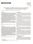
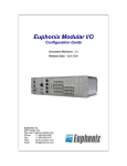
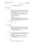
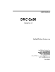
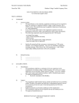
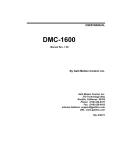
Multi-axis Brushless/Brush Servo Amplifier
AMP-19520/40
Rev. 1.0d
By Galil Motion Control, Inc.
Galil Motion Control, Inc.
270 Technology Way
Rocklin, California 95765
Phone: (916) 626-0101
Fax: (916) 626-0102
Internet Address: [email protected]
URL: www.galilmc.com
Rev 01/10
THIS PAGE LEFT BLANK INTENTIONALLY
Using This Manual
This user manual provides information for proper operation of the AMP-19520 and AMP-19540 multiaxis amplifiers. The AMP-19520/40 has been designed to work with both brushless and brush-type
servo motors and installation will vary depending upon which type of motor is used.
Although the axes are labeled X, Y, Z, and W on the AMP-19520/40, note the following axis naming
conventions:
Total
Controller Axes
Amplifier(s) Used
Controller Axis Names
Amplifier Axis Names
(per Galil software)
(per AMP-19520/40 silkscreen)
1
AMP-19520
A
X
2
AMP-19520
A, B
X, Y
3
AMP-19540
A, B, C
X, Y, Z
4
AMP-19540
A, B, C, D
X, Y, Z, W
5
AMP-19540 and AMP-19520
A, B, C, D, E
X, Y, Z, W, X
6
AMP-19540 and AMP-19520
A, B, C, D, E, F
X, Y, Z, W, X, Y
7
Two AMP-19540s
A, B, C, D, E, F, G
X, Y, Z, W, X, Y, Z
8
Two AMP-19540s
A, B, C, D, E, F, G, H
X, Y, Z, W, X, Y, Z, W
WARNING: Machinery in motion can be dangerous! It is the responsibility of the user to design
effective error handling and safety protection as part of the machine. Galil shall not be liable or
responsible for any incidental or consequential damages.
Contents
INTRODUCTION .................................................................................................................................................................5
ELECTRICAL SPECIFICATIONS ...........................................................................................................................................5
HEAT TRANSFER ...............................................................................................................................................................5
MATING CONNECTORS .....................................................................................................................................................6
SETUP ...............................................................................................................................................................................8
Amplifier Setup............................................................................................................................................................8
Brushless Motor Setup ................................................................................................................................................9
Brush Motor Setup ......................................................................................................................................................9
JUMPERS .........................................................................................................................................................................10
Shunt Regulator (90V, 64V, 33V)..............................................................................................................................10
Amplifier Error Monitoring ......................................................................................................................................10
OPT......................................................................................................................................................................................... 10
ELO ........................................................................................................................................................................................ 10
EFGH...................................................................................................................................................................................... 10
7_IN ........................................................................................................................................................................................ 10
ABORT................................................................................................................................................................................... 10
CHOP...................................................................................................................................................................................... 10
Amplifier Gains .........................................................................................................................................................10
AG2 ........................................................................................................................................................................................ 11
AG0 ........................................................................................................................................................................................ 11
AU1 ........................................................................................................................................................................................ 11
Optoisolation Power .................................................................................................................................................11
EROUT ................................................................................................................................................................................... 11
INCOM ................................................................................................................................................................................... 11
EXT RESET ........................................................................................................................................................................... 11
LSCOM................................................................................................................................................................................... 11
Analog Ground..........................................................................................................................................................11
GND/AG................................................................................................................................................................................. 11
PGM........................................................................................................................................................................................ 11
External Amplifiers ...................................................................................................................................................12
MCM ...................................................................................................................................................................................... 12
AEN ........................................................................................................................................................................................ 12
PWM....................................................................................................................................................................................... 12
SGN ........................................................................................................................................................................................ 12
INDICATOR LIGHTS AND ERRORS....................................................................................................................................12
POWER (and Under-Voltage)..................................................................................................................................12
OVERCURRENT.......................................................................................................................................................12
OVERVOLTAGE.......................................................................................................................................................12
OVERTEMP..............................................................................................................................................................13
ERROR......................................................................................................................................................................13
PINOUT ...........................................................................................................................................................................14
4 • Contents
AMP-19520/40
Introduction
The AMP-19540 (four-axis) and AMP-19520 (two-axis) are multi-axis brush/brushless amplifiers that are capable of
handling 500 watts of continuous power per axis. The amplifier accepts 18-80 VDC and includes breakout for all
controller I/O, including encoders, Hall-effect switches, digital inputs, digital outputs, and analog inputs (Optima
controllers only). The AMP-19520/19540 Brushless drive module can be connected to any of the following Galil
controllers via the 100-pin high density connector:
Optima Series: DMC-1200, 13x8, 1600, 1700, 1800, 2000, 2100, 2200
Econo Series: DMC-18x2, 21x2
Please use the AMP-20520/40 instead with the DMC-21x3.
Electrical Specifications
The AMP-19520/40 is a brush/brushless trans-conductance PWM amplifier. The amplifier operates in torque mode and
will output a motor current proportional to the command signal input.
Input Voltage:
18-80
VDC
Continuous Current:
7 amps
Peak Current
10 amps
Amplifier Gain
0.4, 0.7, or 1.0 A/V (jumper adjustable)
Switching Frequency
60 kHz (up to 175 kHz available--contact Galil)
Minimum Load Inductance
0.5 mH (low inductance option available)
Communtation Angle
120o (60o option available)
Heat Transfer
If all AMP-19520/40 axes run at less than 3 A, thermal cooling is usually not required. For axes running greater than 3
A, it is up to the user to make sure that heat is adequately transferred out of the amplifier. If the amplifier is not properly
cooled, it may reach 110 oC and the amplifier will shut down. All electrical components inside the amplifier that
generate appreciable heat are in thermal contact with the metal back plate, so consideration should be taken to mount the
amplifier to a thermally conductive surface (e.g. metal), preferably with thermal grease.
AMP-19520/40
Introduction • 5
Figure 1. AMP-19540
Mating Connectors
POWER (8 pin)
MX, MY, MZ, MW (4 pin)
6 • Mating Connectors
Connector
AMP: 770579-1
AMP: 172167-1
Terminal Pins
AMP: 171639-1
AMP: 171639-1
AMP-19520/40
Layout and Dimensions
MW
MZ
MY
MX
POWER
+VS
GND
POWER
A
C
90V
-ERR/INCOM
RESET
INCOM
-EROUT
X
+5V
Y
RST/LSCOM
Z
-EXT RESET
W
33V
SHUNT
REGULATOR
MOTOR
64V
B
GALIL MOTION CONTROL
OPT
Z
Y
X
J3
W
AG
1
AG1 NO JUMPER
ANALOG
GND
+5V
AU1
AU1
AG0
AG2
AG0
CHOP
CHOP
AU1
AU1
AG0
AG2
CHOP
AG1 NO JUMPER
POWER
LSCOM
ABORT
AG2
7_IN
AG0
CHOP
AMP
ERR
EFGH
AG2
MADE IN USA
ELO
AUX I/O
OVERCURRENT
1
1
PGM
1
1
1
OVERVOLTAGE
OVERTEMP
ERROR
SPI
1
AMP-19540
W
AUX ENC.
1
Z
J3.31
MCM
1
PWM
AEN
SGN
J3.16
Y
J3.1
MCM
PWM
AEN
SGN
J3.17
X
J3.39
MCM
PWM
AEN
J3.25
MCM
SGN
J3.9
PWM
AEN
J1
SGN
J3.40
1
Figure 2. AMP-19520/40 Dimensions
Overall Dimensions: 8.75” x 6.80”
AMP-19520/40
Mating Connectors • 7
Setup
Connect an unregulated DC power supply (18-80 V) to the POWER connector. Before applying drive power for the first
time, take appropriate safety precautions: set a small error limit (ER *= 1000), set Off on Error for all axes (OE *= 1),
and set a low torque limit (TK *= 2; TL *= 2).
Amplifier Setup
Select the amplifier gain that is appropriate for the motor. The amplifier gain can be set to 0.4 A/V (AG0 jumper), 0.7
A/V (no AG jumper), and 1.0 A/V (AG2 jumper). This is the only jumper setting required to begin turning a motor;
however, more jumper settings may be required to configure the optional shunt regulator, amplifier error monitoring,
optoisolation power, and external amplifiers (see next section, Jumpers).
Peak and continuous torque limits can be set through TK and TL respectively. The TK and TL values are entered in
volts on an axis-by-axis basis. The peak limit sets the maximum voltage that will be output from the controller to the
amplifier. The continuous current sets what the maximum average current is over a quarter second interval. The
following figure captured with WSDK shows the continuous and peak operation. The continuous limit was 2 V and the
peak limit was 10 V (if the gain is set to 0.7 A/V, a torque limit of 2 causes the amplifier to never exceed 1.4 A on the
specified axis).
Figure 3. Peak and Continuous Current Operation
8 • Setup
AMP-19520/40
Brushless Motor Setup
To configure an axis for brushless motor operation, connect the encoders and Hall sensors (15-pin high density X, Y, Z,
or W), home switches, and limit switches (AUX I/O J3). The AMP-19520/40 can normally only be connected to a
brushless motor with 120 degree Hall commutation. 60 degree Hall commutation is an option and can be specified by
ordering AMP-19540-COM60.
Next, connect the three motor power leads to the phase A, B, and C connections for the axis (MX, MY, MZ, or MW).
The motor wiring must correspond to the Hall wiring, so if the motor manufacturer indicates how to do this, simply
connect the power leads as specified. Otherwise, you will need to try up to six motor power lead combinations (keeping
the hall sensor wiring fixed) until smooth motion results. Three of the combinations result in a stall condition (no
torque), two result in jerky motion in one direction but smooth in the other, and the last (correct) combination results in
smooth movement in both directions. The following table will help you connect all six combinations:
Table 1. Aid to connect all six motor power lead combinations
Phase A
Power Lead 1
Power Lead 1
Power Lead 2
Power Lead 2
Power Lead 3
Power Lead 3
Phase B
Power Lead 2
Power Lead 3
Power Lead 3
Power Lead 1
Power Lead 1
Power Lead 2
Phase C
Power Lead 3
Power Lead 2
Power Lead 1
Power Lead 3
Power Lead 2
Power Lead 1
Behavior
Once the motor is wired correctly, the controller is ready to perform closed-loop motion.
Brush Motor Setup
To configure an axis for brush motor operation, connect the two motor leads to the Phase A and Phase B connections for
the axis (MX, MY, MZ, MW). Leave the C Phase disconnected. Connect the encoders (15-pin high density X, Y, Z,
W), home switches, and limit switches (AUX I/O J3). The amplifier has no need for the Hall inputs when operating
brush motors.
AMP-19520/40
Setup • 9
Jumpers
Shunt Regulator (90V, 64V, 33V)
The AMP-19520/40 has an OPTIONAL internal shunt regulator (for example, order AMP-19540-SR). A shunt regulator
is a power resistor and switch connected across the power supply used to dissipate energy fed back to the amplifier from
the motor. This keeps the power supply voltage from exceeding hazardous levels.
The shunt regulator is unused when no jumper is installed (an OVERVOLTAGE error condition will occur if the supply
voltage exceeds 94 V). Install a single jumper on the desired voltage threshold (90V, 64V, or 33V) to use the shunt
regulator. The switch will close when the power supply’s capacitor exceeds the voltage threshold. The voltage threshold
chosen should be the one just higher than the nominal supply voltage (e.g. use the 33 V jumper when using a 24 V
supply).
For more information see Application Note 5448: Shunt Regulator Operation
Amplifier Error Monitoring
When an amplifier error occurs (UNDERVOLTAGE, OVERCURRENT, OVERVOLTAGE, or OVERTEMP), the AMP
ERR digital output is brought low. Insert either the 7_IN or ABORT jumper to notify the controller of these conditions.
OPT
Reserved
ELO
ELO (Emergency Lock Out) is a jumper setting on the AMP-195x0 which configures the amplifier’s behavior when the
abort line goes low. With the jumper absent (default), the behavior of the motors is subject to the OE command. If the
jumper is installed, the amplifiers will be immediately shut down, leaving the axes in a free-spin state. Having the ELO
jumper installed is similar to OE1, except that the amplifiers are disabled in hardware rather than firmware. WHEN
ELO IS INSTALLED, OE SHOULD BE SET TO 1. To recover, issue MO; SH. When ELO is active, the overcurrent
and overvoltage lights will turn on.
EFGH
reserved
7_IN
Install this jumper to tie the amplifier’s AMP ERR digital output to digital input 7 on the controller. This jumper allows
the controller to handle an amplifier error condition for example by issuing the ST command from #ININT (see II in the
command reference). INCOM MUST BE POWERED WITH OPTIMA CONTROLLERS
ABORT
Install this jumper to tie the amplifier’s AMP ERR digital output to the controller’s Abort digital input. When the Abort
input is brought low, the controller will stop program execution and bring all axes to an instantaneous stop (OE0) or
allow the motors to coast (OE1). INCOM MUST BE POWERED WITH OPTIMA CONTROLLERS
CHOP
Install for chopper mode (for low inductance motors), otherwise the amplifier operates in inverter mode (Rev D or
newer).
Amplifier Gains
If AG2 and AG0 are not installed, the amplifier gain on that axis is 0.7 A/V (medium).
10 • Jumpers
AMP-19520/40
AG2
Sets the amplifier gain on that axis to 1.0 A/V (high)
AG0
Sets the amplifier gain on that axis to 0.4 A/V (low)
AU1
No jumper for normal current loop gain. Jumper for high current loop gain.
The normal current loop gain should be chosen for low inductance motors (less than 5 mH with a 24V supply or 10 mH
with a 48 V supply).
Optoisolation Power
These jumpers set the power source for the controller’s digital input optoisolators. If an external supply is used for the
general purpose inputs, the Error digital output is unavailable. If an external supply is used for the limit and home switch
inputs, the Reset digital input is unavailable.
NOTE: If the AMP-19540 will be used with a controller that has optoisolation, such as an Optima or Accelera series
product, and the system requires an isolated supply greater than 5V, please consult Galil.
EROUT
Jumper EROUT to ERR/INCOM to bring out the controller’s error digital output to AUX I/O J3 pin 30.
INCOM
Jumper INCOM to ERR/INCOM to bring the controller’s digital input common to AUX I/O J3 pin 30 (Optima series
only). An external DC power supply between 5 and 24 V must be connected to this pin to use the controller’s general
purpose digital inputs and Abort input.
Jumper INCOM to +5V to tie the controller’s digital input common to the controller’s 5 V power supply (Optima series
only). This bypasses the optoisolation for the digital inputs.
EXT RESET
Jumper EXT RESET to RST/LSCOM to bring out the controller’s Reset digital input to AUX I/O J3 pin 44.
LSCOM
Jumper LSCOM to RST/LSCOM to bring the controller’s limit/home switch common to AUX I/O J3 pin 44 (Optima
series only). An external DC power supply between 5 and 24 V must be connected to this pin to use the controller’s
limit and home switches.
Jumper LSCOM to +5V to tie the controller’s limit/home switch common to the controller’s 5 V power supply (Optima
series only). This bypasses the optoisolation for the limit and home switch inputs).
Analog Ground
GND/AG
Insert jumper when using a DMC-2000, 2100, or 2200 controller. This ties the analog (+/-12 V) ground to digital (5 V)
ground.
PGM
reserved
AMP-19520/40
Jumpers • 11
External Amplifiers
These jumpers must be set if external amplifiers are connected to the controller through the AMP-19520/40.
Install MCM and AEN if the axis drives an external servo amplifier (other than the AMP-19520/40). That axis’s PWM
and SGN digital outputs will be inaccessible.
Install PWM and SGN if the axis drives an external stepper amplifier (or external PWM-input servo amplifier). That
axis’s MCM and AEN outputs will be inaccessible. The SM jumper(s) must be installed on the controller.
MCM
Jumper MCM to J3.x to bring that axis’s Motor Command Analog Output to the J3 AUX I/O J3 connector at pin x.
AEN
Jumper AEN to J3.x to bring that axis’s motor Amplifier Enable Digital Output to the J3 AUX I/O J3 connector at pin x.
PWM
Jumper PWM to J3.x to bring that axis’s Pulse Width Modulation Digital Output to the J3 AUX I/O J3 connector at pin
x.
SGN
Jumper SGN to J3.x to bring that axis’s Sign Digital Output to the J3 AUX I/O J3 connector at pin x.
Indicator Lights and Errors
The amplifier is protected against under-voltage, over-current, over-voltage, and over-temperature conditions, which are
indicated by LEDs. It responds to these conditions by disabling and setting it’s AMP ERR digital output low. The
controller can be informed of amplifier errors via AMP ERR by installing the 7_IN or ABORT jumpers.
POWER (and Under-Voltage)
Indicates whether amplifier power (18-80 VDC) AND board-level power (5, +/-12 VDC) is applied (both the POWER
connector and 100 pin J1 connector must be connected for this indicator to light).
If the power supply voltage drops below 12 V (Under-Voltage), the amplifier disables and the POWER light will turn
off. The amplifier will automatically re-enable once the supply rises above the 12 V.
OVERCURRENT
If the current on any axis exceeds 10 A, the amplifier will disable. The amplifier will remain disabled until the controller
sets all Amp Enable lines low and subsequently sets at least one high (issue MO; SH to reset). This fault indicates a
system-level problem and is usually due to a short across the motor leads or a short from a motor lead to ground.
OVERVOLTAGE
Indicates that the amplifier power (18-80 VDC) applied to the POWER connector has risen above 94 V due to
regenerative energy fed back from the motor. The amplifier will short the motor leads (regenerative braking) and will
automatically return to normal operation when the supply drops below 89 V.
12 • Indicator Lights and Errors
AMP-19520/40
OVERTEMP
If the heat sink temperature rises above 110 °C the amplifier disables and will automatically re-enable when the
temperature drops below 110°C.
ERROR
Reflects the status of the controller’s (NOT the amplifier’s) error digital output. This indicator lights under the following
conditions:
(1)
(2)
(3)
(4)
when the RESET button on the AMP-19520/40 is pushed (this toggles the controller’s Reset digital input)
momentarily lights when power is applied to the controller
one or more of the controller’s axes is not following well (TE exceeds ER)
when a controller hardware failure occurs (e.g. 5 V supply out of tolerance, corrupted firmware…).
Note: Do not “hot swap” the motor power connections. If the amp is enabled when the motor connector is connected
or disconnected, damage to the amplifier can occur. Galil recommends powering the controller and amplifier down
before changing the connector.
AMP-19520/40
• 13
Pinout
POWER
8-pin AMP
Mate-n-lock II
1 Earth
2 +VM (18 V–80 V)
3 +VM (18 V–80 V)
4 +VM (18 V–80 V)
5 Ground
6 Ground
7 Ground
8 Ground
MX, MY, MZ, MW
Motor Output 4-pin
AMP Mate-n-lock II
1 Earth
2A
3C
4B
X, Y, Z, W
15-pin Hi-density
Female D-sub
1 I+
2 B+
3 A+
4 AB+
5 Ground
6 I7 B8 A9 AA10 Hall A
11 AA+
12 AB13 Hall B
14 Hall C
15 5 V
SPI
9-pin Female D-sub
1 Reserved
14 • Pinout
ANALOG (Optima
Controllers Only)
15-pin Male D-sub
1 Ground
2 Analog input 1
3 Analog input 3
4 Analog input 5
5 Analog input 7
6 Ground
7 -12 V
85V
9 Ground
10 Analog input 2
11 Analog input 4
12 Analog input 6
13 Analog input 8
14 Ground
15 +12 V
AUX ENC (connects
to controller)
25-pin Male D-sub
15V
2 AAX+
3 ABX+
4 AAY+
5 ABY+
65V
7 AAZ+
8 ABZ+
9 AAW+
10 ABW+
11 Reserved
12 Reserved
13 Reserved
14 Ground
15 AAX16 ABX17 AAY18 ABY19 Ground
20 AAZ21 ABZ22 AAW23 ABW24 Reserved
25 Reserved
AUX I/O
44-pin Hi-density
Female D-sub
1 PWM/MCMD Z
2 Output 6
3 Output 8
4 Output 5
5 Output 2
6 Abort*
7 Input 6
8 Latch Z/Input 3
9 SIGN/AEN Y
10 Encoder compare
output
11 Reverse limit X
12 Reverse limit Y
13 Reverse limit Z
14 Reverse limit W
15 Forward limit W
16 SIGN/AEN W
17 SIGN/AEN Z
18 Output 7
19 Output 4
20 Output 1
21 Output 3
22 Input 7
23 Latch W/Input 4
24 Latch X/Input 1
25 PWM/MCMD X
26 Home X
27 Home Y
28 Home Z
29 Home W
30 Error
Output*/INCOM
31 PWM/MCMD W
32 5 V
33 5 V
34 Ground
35 Ground
36 Input 8
37 Input 5
38 Latch Y/Input 2
39 PWM/MCMD Y
40 SIGN/AEN X
41 Forward limit X
42 Forward limit Y
43 Forward limit Z
44 Reset*/LSCOM
*Active Low
AMP-19520/40