1
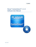
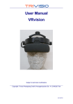
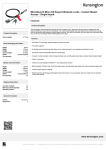
Planar TD3200
Transparent Display
USER MANUAL
www.planar.com
2
TD3200 User Manual
Table of Contents
Precautions
4
Introduction
Getting to Know Your Planar Transparent Display Monitor
5
Display Box Feature Descriptions
5
Placing Your Monitor
6
Attaching Electrical and Video Connections
7
Using Magnetic Vinyl
8
Setup
Presentation of Your Material in the TD3200 Display Box
9
Cleaning Your TD3200
10
Appendix
11
Troubleshooting
11
Specifications
12
Compatible video modes
13
Regulatory Summary
14
Support and Service
15
TD3200 User Manual
3
Usage Notice
WARNING – Please do not open or disassemble the product
as this may cause electric shock.
Precautions
Follow all warnings and precautions as recommended in this user’s manual to
maximize the life of your unit and to insure the safety of the users.
Do:
•
•
•
•
•
•
•
Turn off the display before loading content into the display box
Operate and store your transparent display box in a clean,
dry environment
Be certain to determine your table, countertop or mount can
support the 55lb (121kg) weight of the TD3200 display box plus
weight of the added contents
Disconnect the power plug before cleaning
Clean front glass using a soft clean cloth moistened with
commercial mild window glass cleaner or 50/50 mixture of
water and isopropyl alcohol
Use a soft cloth moistened with mild detergent to clean the
enclosure housing
Remove lint and other loose debris from the inside surface of the
LCD with a dry lint-free soft cloth
Don’t:
•
•
•
•
4
Do not look directly at the LED illumination system in operation
with access door removed
Do not touch the front or the inside display surface with sharp or
hard objects
Do not use abrasive cleaners, waxes or solvents for your cleaning
Do not spray cleaner inside the display enclosure. We recommend
wiping the interior with a soft cloth that has been moistened with
a mild detergent
TD3200 User Manual
Introduction
Getting to Know Your Planar Transparent Display Monitor
Display Box Feature Descriptions
Front View
Back View
Bottom View
TD3200 User Manual
5
Placing your Monitor
When used on a countertop or other supporting surface, the TD3200 can be
oriented in landscape or portrait mode. Be certain to determine the table
or countertop can safely support the 55lb (121kg) weight of the TD3200
display box plus the weight of the added contents. In landscape mode we
recommend the access door be oriented on top but in portrait mode there is
no preferred orientation as to which short side is on top.
The TD3200 can also be mounted using the VESA Flat Panel Mounting
Physical Mounting Interface Standard incorporated into the back plate of
the display. Please refer to the REAR VIEW drawing in the prior section for
mounting pattern dimensions. Again, be certain to check to make sure
the mount is capable of supporting the weight of the TD3200 display box
plus contents. Planar recommends using UL or similarly tested mounting
hardware. In mounting the display on a stand using the 200 mm square
VESA pattern, use the four adjacent holes in the center of the unit. We don’t
recommend using the outer 200 mm square pattern by itself.
To mount the monitor on a swing-arm or other mounting fixture, follow the
instructions included with the mounting fixture to be used. Again, Planar
recommends using UL or similarly tested mounting hardware.
If the monitor is placed against a wall or with the backside against a
countertop, we recommend installing the four rubber feet into the
threaded inserts located at the corners of the backside of the display.
This will permit spacing for cooling ventilation and also allow room for
the power and video cables.
WARNING – For wall or swing-arm VESA mounting, you must
select the proper screw length! Your M6 mounting screws
should protrude no more than 5/8" (16 mm) into the VESA
mount threaded holes (see REAR VIEW figure in prior section).
Use of longer screws can damage the monitor. For example,
if your VESA mounting bracket is ¼" (6mm) thick, use 20
or 22 mm long M6 screws.
6
TD3200 User Manual
Attaching Electrical and Video Connections
Power is supplied to the TD3200 display box through the four pin connector
of the power supply brick. Attach this to the “48C DC input” plug on the
Connection Interface Plate (see figure below). The power switch controls both
the video and the internal illumination for the display box.
Your computer or media player can either employ an HDMI or DisplayPort
output to interface with the TD3200. No special additional hardware is needed.
Detail of Connection Interface Plate
NOTICE – If the graphics card of your computer or player doesn’t
auto-sync with the TD3200, we recommend a manual display
setting of 1366 x 768 for best results. We have listed all the
compatible video modes of your TD3200 in the Appendix
(on page 13) for your reference.
TD3200 User Manual
7
Using Magnetic Vinyl
We have fabricated the TD3200 display box from aluminum to provide a
sturdy but relatively lightweight enclosure. In addition the access door and
other three side panels are made from steel to allow the user to employ these
surfaces for additional messaging or decoration through use of magnetic
vinyl. See examples below.
This material can quickly change the appearance of the exterior of the box to
compliment the video content and/or to blend in with other surfaces in the
environment. Printed magnetic vinyl is readily available online or at printing
service vendors.
Magnetic Vinyl Dimensions
8
TD3200 User Manual
Setup
Presentation of Your Material in the TD3200 Display Box
Place materials to be displayed inside the display box using the access door on
one long side of the enclosure. Loosen the fasteners using a standard Philips #1
or #2 screwdriver. We have included a small screw driver with a clamp mount
that can be positioned on the back of the TD3200 for easy storage. We have also
included a magnetic lift tool with the display box that can be used to assist in
raising the steel access door after loosening the fasteners. You can store the lift
tool by attaching it to a steel plate found in the accessories bag. After removing
the adhesive liner, the plate can be attached on the backside of the display to
provide a place to store the lift tool.
You should experiment with placement of the objects to be displayed in the
TD3200 to optimize their appearance and interaction with your video content.
You will find that the brightness of display box and the legibility of the screen
content can be affected by the color of objectives placed in the display box. For
best results we suggest avoiding large areas of dark colors inside the display box.
Most conventional digital signage video content can be used with the TD3200,
but enhancements to the content are possible to optimize the attentiongrabbing effect you and your customers will see in using the Planar transparent
display box. In preparing video content for the TD3200 driving the LCD to white
will produce the highest transparency while black screen features will result in
the most opacity. Intermediate colors will have intermediate transparency. Note
that slide-show presentation software, such a Microsoft Powerpoint™, can be
used to create simple but effective content for the TD3200.
In order to maximize the brightness of the TD3200 we have provided an
extremely high level of white light illumination inside the display box.
In addition to enhancing the appearance of objects inside the box and of the LCD
display, this intense light level can be used to drive a photovoltaic turntable to
further enhance the eye-catching performance of your Planar transparent display
box by rotating your interior content. These light-driven turntables are available
online: search using the keywords: “solar turntable”. Most of these turntables have
a limited weight capacity.
NOTE: While there is almost no ultraviolet light emitted from the white LEDs we
employ, the white light is sufficiently bright to cause potential photobleaching
of materials susceptible to light-induced color fading. We recommend testing
of light fastness of materials to be displayed for an extended period (weeks to
months) in the display box.
TD3200 User Manual
9
Cleaning
The anti-reflection coating on the front glass of your TD3200 should be
cleaned with standard glass cleaner and a soft cloth. In order to remove
fingerprints effectively it is usually better to wet the cloth with the
cleaning solution and work on small sections of the glass at a time rather
than starting to clean the whole surface at once.
The exterior of the TD3200 can be cleaned with a standard water-based
cleaning solution and a cloth. The interior of the display box can be
cleaned with the same materials.
BE CERTAIN TO TURN OFF THE POWER TO THE DISPLAY BOX WHEN
CLEANING THE INTERIOR OF THE UNIT. APPLY THE CLEANING SOLUTION
TO THE CLOTH. DO NOT SPRAY CLEANING SOLUTION INTO THE INTERIOR
OF THE DISPLAY BOX.
10
TD3200 User Manual
Appendix
Troubleshooting
A properly-functioning TD3200 will show a “splash screen” when power is first
applied. If a suitable video source is attached, the screen will then display
whatever video image is being sent to the TD3200 shortly after the splash
screen appears. Note that when power is applied you should also see light
from the LEDs located around the perimeter of the AMLCD screen. When
power is being supplied to the TD3200 power supply, the indicator light on
the power brick will glow green.
Possible Problem – After setup, the switch on the Connection Interface
Plate (see page 7) has been turned on and no image appears. In addition, the
LEDs in the box are not functioning. This probably means no power is being
applied to the display box. Items to check:
• Verify the power brick is plugged into a power source. Note: if the power
brick is receiving power, a green LED on the brick will be lit.
• Make sure the power cord is securely attached to the power brick.
• Check to see the output plug from the power brick is properly inserted in
the plug located in the Connection Interface Plate.
Possible Problem – The splash screen appears after power is turned on, but
a “no sync” message appears on the screen and afterward the monitor shows
no image. This usually means no recognizable video signal is being received
by the display box. Items to check:
• Make sure the video cable is properly plugged in at the video source
(computer or media player).
• Verify the other end of the same video cable checked previously is
securely plugged into either the HDMI or DisplayPort receptacle in the
Connection Interface Plate (see page 7).
• If an adapter is being used as part of the video cable, check to confirm
the two plugs are properly seated.
• If you are using a DVI plug from the video source, check to make sure
there are no bent pins in the plug.
• Verify that the output of your computer or player is one of the formats
listed on page 13 of this document.
If these troubleshooting instructions do not resolve the problem, please call
1.866.PLANAR1 and select option 1 to determine the next steps.
TD3200 User Manual
11
Specifications
TD3200 - Transparent Display Monitor
12
Product Name
TD3200
Planar Part Number
997-6821-00
Viewable Size
31.25" diagonal (27.3" x 15.2")
Viewing Angle (Typical)
178° Horizontal and Vertical
Response Time (G-to-G, Typical)
8 ms
Brightness (Typical)
350 cd/m2
Native Display Resolution
1366 x 768
Aspect Ratio
16:9
Color Palette
16.7 million colors
Pixel Pitch
0.511 mm
Refresh Rate
50 to 60 Hz
Exterior Dimensions (WxHxD)
29.5" (749 mm) x 17.5" (445 mm) x 15.0" (381 mm)
Interior Dimensions (WxHxD)
27.25" (692 mm) x 15.25" (387 mm) x 13.5" (343 mm)
Access Door Dimensions
24.2" (615 mm) x 8.8" (223 mm)
Display Weight
55.1 lbs (25.0 kg)
Video Inputs
Digital (HDMI, DisplayPort)
Power Supply
External AC adapter, 48V DC
Power Requirements
100-200 VAC (50/60 Hz)
Power Consumption
125W
VESA Compatible/ Location
Built-in 200 x 200 and 400 x 200 mm VESA, Back
Service and Support
3-Year Warranty
Product Approval
NRTL Listed, FCC-Class A, CE, RoHS
In the Box
TD3200 32" LookThru LCD Monitor, Power Adapter
and Cord, HDMI Cable, User’s Guide, Quick Start
Guide, feet and fasteners, access door lift tool and
mount, screwdriver and mount.
TD3200 User Manual
Compatibility Modes
Mode
Resolution
V-Frequency (Hz)
VGA
640 x 480
60
WVGA
800 x 480
60
SVGA
800 x 600
60
XGA
1024 x 768
60
WXGA
1280 x 720
60
WXGA
1280 x 768
60
HD
1366 x 768
60
TD3200 User Manual
13
Compliance Information
Federal Communication Commission Radio
Frequency International Statement
This equipment has been tested and found to comply with the limits for a
Class A digital device pursuant to Part 15 of the FCC Rules. These limits are
designed to provide reasonable protection against harmful interference with
the equipment is operated in a commercial environment. This equipment
generates, uses and can radiate radio frequency energy and, if not installed
and used in accordance with the instruction manual, may cause harmful
interference to radio communications. Operation of this equipment in a
residential area is likely to cause harmful interference in which case the user
will be required to correct the interference at their own expense.
14
TD3200 User Manual
Support and Service
Planar is a US company based in Beaverton, Oregon and Espoo, Finland with a
worldwide sales distribution network.
Visit Planar at http://www.planar.com/support for product registration,
operations manuals, line drawings, touch screen drivers, warranty information
and access to Planar’s Technical Library for online troubleshooting.
To speak with Planar Customer Support please have your model and serial
number available and dial one of these numbers:
Americas Support
Tel: 1-866-PLANAR1 (866-752-6271) or +1 503-748-1100
Hours: M-F, 8am - 8pm Eastern Time | M-F, 5am - 5pm Pacific Time
TD3200 User Manual
15
Planar Systems, Inc.
Customer Service
24x7 Online Technical Support: http://www.planar.com/support
Americas Support
Tel: 1-866-PLANAR1 (866-752-6271) or +1 503-748-1100
Hours: M-F, 8am - 8pm Eastern Time | M-F, 5am - 5pm Pacific Time
© 2012 Planar Systems, Inc. Planar is a registered trademark of
Planar Systems, Inc.
Other brands and names are the property of their respective owners.
Technical information in this document is subject to change without notice.
This document contains proprietary information that is protected by
copyright. All rights are reserved. No part of this document may be
reproduced, translated to another language or stored in a retrieval system, or
transmitted by any means, electronic, mechanical, photocopying, recording,
or otherwise, without prior written permission.
Document No. 020-1199-00A