1
United States Patent [191
[11]
Patent Number:
4,604,708
Lewis
[45]
Date of Patent:
Aug. 5, 1986
[54]
ELECTRONIC SECURITY SYSTEM FOR
EXTERNALLY POWERED DEVICES
[76] Inventor:
21
A
[ 1
[22]
pp
Filed:
OTHER PUBLICATIONS
Byte, Word Protection for Your Computer, by R. Jordan
Kreindler, Mar, 1979, pp, 194-195.
Primary Examiner—Gareth D. Shaw
Gainer R. Lewis, 7018 Paci?c View
Dr" Hollywood’ Cahf' 90068
1' NO‘: 669 727
Assistant Examiner—Daniel K. Dorsey
’
Nov. 8, 1984
Atlorney. Agent, or Firm-Blakely Sokoloff Taylor &
Zafman
[57]
[63]
ABSTRACT
Related US. Application Data
commumion of Sen No_ 328030, Dec 7, 198‘, abam
An electronic security system for a device requiring an
external power source is disclosed. The security system
dorm]
includes a microcomputer which executes a power-on
routine stored in memory whenever the microcomputer
[51]
Int. Cl.4 ...................... .. G08B 13/06; GO6F l/OO;
iS initially coupled to a power source. The user must
[52]
[58]
B6OR 25/00
US. Cl. .............................. .. 364/900; 340/82531
Field of Search ......... .. 340/8253, 825.31, 825.32,
enter a primary security code which is compared to a
predetermined code, and if the codes match, the mi
crocomputer signals a relay to provide power to the
340/825.34; 364/200, 900
device, thereby enabling it. Once enabled, the user need
[56]
not reenter the security code as long as the external
source of power to the device remains uninterru ted. A
secondary security code may be entered if the primary
References Cited
U S PATENT DOCUMENTS
~
' '
kaul'llzel e‘ 31' '
4‘3l0‘720 3:982 Crick]:
""
4,333,090
6/1982
4,447,890
the Secondary code, [he microcomputer displays an
22(1)
"""" "
4'333'074 6/1982 smher'lana
4,366,466 12/1982
p .
code has been forgotten or misplaced. Upon entry of
4,103,289 7/1978 Kolber .......................... .1340/82532
12/
4
encrypted version of the primary security code. If an
{Mr/£500
incorrect code is entered by the user, the microproces
"""_"'540/825_3
sor executes an alarm routine which may include visual
Hirsch ............... ,.
340/8253
Lutz .............. ..
and audlble wammgs
340/8253]
5/1984 Duwiel et al. .................... .. 364/900
16 Claims, 2 Drawing Figures
24
/
D U D D III El
El D Cl C El D
1: 1:1 1:1 1:1 :1 u
j‘
25v
01:24:;
{'12:
if
3"
M
h
MC
A0044
.4»
:>
(wrm 4.6mm‘!
n\
a‘
616m“:
DC
@411? awn/£4‘
2D
I)’
(“If
MA’
SW49’
a
DC
56
Mm!
S
"c
1r“,
AC
Army
a
Am
‘C
——>
azt; _._.
,5,
U.S. Patent Aug. 5, 1986
Sheet 1 of 2
4,604,708
BB
amumvmum vaman
/UM“U
2/
“DUB
4O
J
06
0M4 2/
Ago/w
6C
6@Z
M
m&
0_aw
PHr M
“an [.4T40/Ms
C
~
>
Mm
DC
12%
EH 9 Y ae/mse
10 67C
Poms?
60/0/04 7
as
Maw
AC
—»
Pom/£9
£54 A V
[6/
AC
Hi
US. Patent Aug. 5, 1986
[2/769 04/
?wep-ap *
6574/55’
Sheet20f2
4,604,708
1
4,604,708
2
guests, would have to be provided with the particular
ELECTRONIC SECURITY SYSTEM FOR
EXTERNALLY POWERED DEVICES
pass code in order to operate a device so protected,
thereby potentially compromising security. Moreover,
in a home or business equipped with several pass code
This application is a continuation, of application Ser.
No. 328,080, ?led Dec. 7, 1981, now abandoned.
BACKGROUND OF THE INVENTION
1. Field of the Invention
protected devices known in the prior art, the require
ment of remembering which pass code enables which
device would likely prove intolerable. Thus, it is likely
that consumers would not purchase a device which
incorporates a pass code security system as was typical
The invention relates to electronic security systems, 10 in the art prior to the present invention, since any secu
particulary those systems which require a predeter
mined code to be entered by a user in order to gain
access to or enable a device.
2. Prior Art
The escalating crime rate in recent years has
prompted a need for increased security measures to
protect personal property. A frequent target of thieves
rity benefit would be perceived as outweighed by the
inconvenience factor in using the device.
In addition, with systems such as Schulman and
Launzel, it is possible for a thief to alter or destroy the
serial number of a stolen device and render tracing
difficult if not impossible in many cases. Furthermore,
an unauthorized user could likely obtain the pass code
is electronic devices, such as for example, televisions,
radios, microwave ovens, calculators and stereophonic
systems. Due to the portability of many of these modern
by contacting the manufacturer of the device and repre
electronic devices, a thief can, with relative ease, resell
credibility of the inquiring individual. Accordingly,
or “fence" the stolen device after altering or destroying
the manufacturer’s serial number, thus rendering trac
ing by law enforcement agencies difficult if not impossi
senting that he is the true owner, inasmuch as the manu
facturer had no straightforward method to check the
there exists a need for a security system for electronic
devices which is both secure and convenient for the
user.
ble.
25
As will be disclosed below, the present invention
Attempts to secure electronic devices were initially
overcomes the disadvantages associated with pass code
directed toward mechanical means which physically
systems such as Schulman, Launzel, and other prior art
lock or disable the television, calculator or the like.
systems, by providing a unique security circuit which
However, mechanical means have inherent disadvan
tages which serverely limit the practicality of this type 30 requires that a security code be entered only once in
order to enable a device as long as a continuous source
of solution. For example, the mechanical means are
of power is supplied thereto.
typically expensive, and additionally eliminate or re
strict portability which is a major advantage of modern
SUMMARY OF THE INVENTION
electronic devices.
The present invention is most advantageously used in
Electronic solutions to the problem of theft have 35
conjunction with televisions, radio receivers and other
included the use of a security code system which re
electrical devices which require an external power
quires the user to input a predetermined code in order to
source. A microcomputer executes a power-on routine
gain access to or enable the protected device. Thus,
stored in memory each time the device is coupled to the
each time a user desires to operate a device incorporat
power source. The user must enter a primary security
ing a security code system, he must input the predeter
code which is compared with a stored (or algorithmi
mined code.
An example of an electronic system for a solid state
device is disclosed in US. Pat. No. 4,139,864 by Schul
cally generated) code, and if the codes match the device
is enabled. Once enabled, the device may be operated
without reentering the security code as if the security
man. The Schulman security circuit is in part formed on
one of the same micro-electronic “chips” as that of the 45 system were not present, until the power source is re
electronic device itself, thereby preventing a thief from
physically bypassing the circuit. In order to enable the
device, a user must key in a pass code, which when
compared and matched with a preset internal code
allows access to the device.
moved by, for example, a thief unplugging the device
from an AC. line.
If an incorrect security code is entered, the mi
crocomputer executes an alarm routine which may
50 display “HOT” or the like on a digital readout, and may
energize an audible alarm signal.
If the primary security code is misplaced by a user,
the manufacturer or its authorized agent after satisfacto
rily identifying the user provides a secondary code,
porates a microprocessor which executes a predeter
mined sequence of operations upon the activation of the 55 which upon entry into the security system's microcom
puter causes to be displayed an encrypted version of the
device’s power switch. Once a predetermined security
primary security code. The manufacturer using an de
code has been entered by the user, the circuit compares
the inputted code with a code stored in memory and if
cryption algorithm then provides the primary security
a match occurs the communication system is enabled.
code to the user. Additionally, the primary code may be
Systems such as Schulman and Launzel require that 60 cross-referenced to the device’s serial number to facili
An example of an electronic security system for the
control of communication signals is disclosed by Laun
zel, US. Pat. No. 4,179,733. The Launzel circuit incor
the user enter the pass code each time he desires to
make use of the device. For devices such as televisions,
stereo receivers, microwave ovens and other related
items which are frequently used sporadically during the
tate tracing by law enforcement agencies.
BRIEF DESCRIPTION OF THE DRAWINGS
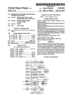
FIG. 1 is a block diagram illustrating the security
course of a day, the requirement of entering a code each 65 system of the present invention.
time operation is desired is extremely inconvenient.
Furthermore, individuals who are not residents of the
consumer’s household, such as baby sitters and house
FIG. 2 is a flow diagram showing the sequence of
steps that the microcomputer executes when power is
first applied to the protected electronic device.
3
4,604,708
DETAILED DESCRIPTION OF THE
INVENTION
A security system for electronic devices such as tele
visions, radio receivers and the like which require an
external source of power is disclosed. In the following
4
it is encountered, then the next operation is the one
determined by following the line marked by a “Y”. If
the condition is not satis?ed, the next instruction is
determined by following the line marked “N". Rectan
gular symbols represent operations which are carried
out by he microcomputer and its associated elements.
An oval symbol represents a starting entry into the
program sequence by virtue of the initial application of
bers, etc. are set forth in order to provide a thorough
power to the microcomputer from logic power supply
understanding of the present invention. However, it
will be apparent to one skilled in the art that the present 0 12 once the device to be protected is plugged in. The
sequence of operations follows the path de?ned by the
invention may be practiced without these speci?c de
arrows. The program is delineated by following the
tails. In other instances, well known circuits and devices
description for purposes of explanation, speci?c num
lines joining the various symbols.
are shown in block diagram form in order not to ob
FIG. 2 indicates the sequence of steps executed when
scure the present invention in unnecessary detail.
Referring now to FlG. 1, the present invention in 5 power is ?rst applied by plugging the protected device
into an A.C. power source. The program begins at the
cludes as a part thereof a microcomputer indicated by
oval marked "Enter on Power-up”. The microcom
Numeral 10. The microcomputer can be any one of a
variety of types currently commercially available. It
will be appreciated from the discussion which follows
that an existing on-board microcomputer of the type
typically used in frequency-synthesized tuning systems
in television and radio may be utilized, with little modi
?cation to those devices which incorporate such tuning
systems.
puter initially executes a "getkey” operation in which it
scans the keypad 24 and awaits the input of the ?rst
digit (or character) of the primary security code. Upon
entry of a ?rst digit by the user, microcomputer 10
compares the entered digit with the ?rst digit of the
predetermined primary security code stored in PROM
34. As is illustrated in FIG. 2, if a match exists the mi
The microcomputer 10 receives DC. power from a
crocomputer executes another “getkey" operation and
DC. logic power supply 12 which, in the presently
compares the second inputed digit or character to the
preferred embodiment, is coupled to an A.C. external
power source 14 by line 16. The logic power supply 12
is also coupled to a relay driver 18 by line 20, which as
will be discussed, controls the operation of the main
power relay 22 which in turn controls the availability of
power to the protected device.
The microcomputer 10 is coupled to a keypad 24 by
line 25, and to a digital display 26 by line 28. In addition,
microcomputer 10 is coupled to a read-only memory
(ROM) 32 and to a programable read-only memory
(PROM) 34. As will be discussed more fully below, the
ROM 32 contains a power-on sequence of operations
which the microcomputer performs whenever external
A.C. power is initially supplied on line 16.
In operation, a device incorporating the present in
vention is supplied with external power, typically by
second digit of the stored primary security code. Mi
crocomputer 10 continues this input and compare se
quence until all of the digits of the security code are
thereby entered and compared.
If the inputted ?rst digit does not match the ?rst digit
of the stored primary code, microcomputer 10 com
pares the ?rst inputted digit with a secondary code also
stored in PROM 34. As will be discussed, this second
ary code provides additional security to the device
since it can only be obtained from the manufacturer or
its authorized agents. If the ?rst inputted digit matches
the ?rst digit of the secondary code, then subsequent
digit entries by the user are compared only with the
stored secondary code. Thus, it will be noted that in the
presently preferred embodiment the primary and sec
ondary codes may not incorporate identical ?rst digits,
in order to avoid ambiguity as to which code mi
coupling line 16 to a household A.C. outlet. The logic
crocomputer 10 is to compare. However, if identical
power supply 12 converts the A.C. current into a DC.
source and provides the requisite DC. current on line 45 ?rst digits are desired, the power-up routine can be
easily modi?ed such that other digits or the like are
17. Microcomputer 10, upon the application of power to
compared to identify which code is being entered. As
the power supply 12 executes a power-on routine which
shown in the ?ow diagram of FIG. 2, upon the proper
is stored in ROM 32. The power-on routine, as will be
entry of all digits of the secondary code, microcom
described, requires the microcomputer to await the
puter 10 displays an encrypted version of the primary
input of a code from keypad 24. As the user inputs a
code, microcomputer 10 compares the keyed in security
code keystroke by keystroke with a predetermined
primary security code stored in PROM 34. If the codes
match, microcomputer 10 signals the relay driver 18 on
line 36 to provide A.C. power to the device by activat
ing the main power relay 22. Power is thereby provided
to the device‘s main power supply 37, or other applica
ble circuit depending on the nature of the device pro
tected. Additionally, once the proper code is entered
microcomputer 10 issues other control and enable sig
nals, as may be required by the particular device which
is protected, such as by way of illustration, frequency
selection, timer, volume and contrast control signals.
security code on digital display 26. It will be appreci
ated, that the encrypted version of the primary security
code may be either stored in a memory location within
the PROM 34 or may be generated by an encryption
algorithm stored within ROM 32 and executed by the
microcomputer.
As shown in FIG. 2, if the ?rst digit or character
entered by the user does not match either the primary
security code or the secondary code as discussed above,
the microcomputer enters an alarm mode and displays
“I-IO'I‘" or some other similar message in the digital
display 26 and does not enable the main power relay 22
through the relay driver 18. Thus, until power is re
With reference to FIG. 2, the power-on sequence of
moved, by for example removing the A.C. plug, the
condition received by the decision is satis?ed at the time
illustrated in FIG. 2, the alarm mode may include an
operations of the microcomputer 10 is described. In the 65 microcomputer will not permit further keyboard entries
and will not enable power to be coupled to the pro
diagrams there shown, diamond shaped boxes with “1'”
tected device through the main power relay 22. As
marks represent decision points in the program. If the
5
4,604,708
optional au_dible alarm tone in the form of a warble
generated by the microcomputer as a digital pulse train
of varying period, and incorporate a ?ashing digital
display. As depicted, if the ?rst inputted digit matches
with either the stored primary or secondary code, any
subsequent digit which when compared fails to match
will automatically send the microcomputer into the
alarm mode.
If all of the digits or characters comprising the pri
mary security code are properly entered, then mi
crocomputer l0 signals relay driver 18 on line 36 to
activate the main power relay 22 thereby providing
power to the protected device. In addition, microcom
puter 10 after a proper code has been fully entered,
performs all other functions as may be required by the
particular device, for example tuning, channel selection
and other similar functions.
6
is believed that a ?ve digit code will provide the desired
level of security without being ungainly for the user.
Additionally, it will be noted that the security codes
may comprise digits, characters, symbols or any combi
nation thereof (hereinafter referred to as alphanumeric
characters) which is appropriate for the speci?c appli
cation of the protected device.
In addition, it will be noted that the secondary code
need not be unique to each device, but may be common
to the entire production run, model or series. Further
more, it will be appreciated that the serial number of a
particular device may be cross-referenced by the manu
facturer to the encrypted version of the primary secu
rity code, or that the PROM 34 may contain the serial
number which can be accessed only upon entry of the
secondary code. Thus, the actual serial number of a
device protected by the present invention can more
Assume for the sake of example that a user plugs a
readily be traced by law enforcement agencies, even
device protected by the present invention into an A.C.
after a thief has altered or destroyed the serial number
outlet. Microcomputer 10 executes the above described 20 located physically on the device itself.
power-on routine and awaits the input of the primary
It will be apparent to one skilled in the art that al
security code. After the user has inputted the code,
though the presently preferred embodiment, as dis
microcomputer 10 enables the protected device by sig
closed, utilizes an AC. source for external power, the
naling the relay driver 18 to provide power to the de
invention can be readily applied to D.C. external
vice’s other systems. Once the proper code has been 25 sources, such as for example an automotive electrical
entered, a subsequent user need not reenter the code in
system. In the case of a D.C. system, the logic power
order to operate the device at a later time. Rather, the
supply 12 would both regulate and provide the appro
user may operate the device as if the security system
was not installed in the device. For example, in the case
of a radio or television, the user would merely switch
the device into the “on" position and operate it in a
normal manner. However, if the protected device is
priate D.C. current and voltage for the microcomputer
10. Similarly, additional obvious modi?cations to the
invention to render it compatible with a D.C. source
would be made. Thus, the present invention may be
adapted to protect electronic devices used on automo
unplugged, as would be the case where a thief has re
biles, aircraft or watercraft, such as, for example, radio
moved it, or if the power fails, then entry of the primary
receivers and tape decks.
code would be required prior to subsequent use since 35
It will be appreciated that if the protected device
once power has returned microcomputer 10 automati
requires a microcomputer for operation, the present
cally executes the above described power-on routine.
invention may be realized without relay driver 18 or the
Assume further that the registered owner of the pro
main power relay 22. Rather than enabling the device
tected device has misplaced or has forgotten the pri
by coupling external power to it, microcomputer 10
mary security code. The owner contacts the manufac 40 may be programmed to withhold all command and
turer of the device or authorized representative, and
control functions necessary to operate the device until a
after supplying proper identi?cation such as, for exam
proper security code is entered. As disclosed in the
ple, name, address, serial number and/ or date and place
presently preferred embodiment, upon the application
of purchase, the manufacturer or its representative
of external power to the device microcomputer 10 exe
supplies the owner with the above described secondary 45 cutes the aforementioned power-on routine. Only upon
security code. The owner plugs the device into an AC.
the entry by a user of a proper code would microcom~
outlet and enters the secondary code on keypad 24. As
puter 10 accept and issue the required control signals
needed to operate the device. Once the correct code is
previously described, microcomputer 10 compares the
entered secondary code with a predetermined code
entered, the user would not be required to reenter the
stored in PROM 34. If the secondary code has been
code as long as power to the microcomputer remains
properly entered, microcomputer 10 displays on digital
uninterrupted. In addition, it will be apparent that al
display 26 an encrypted version of the primary security
though in the presently preferred embodiment the pow
code. The owner reports the encrypted code to the
er-on routine and security codes are stored in ROM 32
manufacturer or its representative, who in turn may
and PROM 34, respectively, memory means within the
enter the encrypted code into a computer which applies 55 microcomputer 10 itself may be used for substantially
a decryption algorithm to recover the actual primary
the same purpose.
code. The manufacturer may then report or mail the
The security system of the present invention provides
actual primary code to the owner, and perhaps charge a
the owner of the device with a level of security hereto
fee for the service. Furthermore, if additional security is
fore not known in the prior art. A thief who removes a
required the primary code may be printed, sealed and
mailed automatically, by for example a computer, such
device protected by the present invention will be unable
that the code is not observable by the manufacturer’s
so protected will likely be deterred from removing it.
Moreover, unlike devices previously known in the art,
personnel.
to use the device, and thus once aware that the device is
The number of digits and/or characters which the
the present invention does not require a user to enter the
primary and secondary codes are comprised of may 65 security code each time the device is to be operated.
vary with any given application of the present inven
Rather, the security code need only be entered when
tion. For example, in cases where higher security is
power is initially applied to the device by plugging it
desired a length of ten digits may be used. However, it
into an AC. socket, or by coupling it to a D.C. power
7
4,604,708
8
source such as an automotive .electrical system. The use
meric character of said ?rst predetermined code and in
of a secondary code to provide an encrypted version of
the absence of a match compares said ?rst received
the primary security code and a decryption algorithm to
recover the true primary code, helps prevent abuses by
personnel who are employed by the manufacturer in
alphanumeric character with a ?rst alphanumeric char
’ acter of said second predetermined code.
tively inexpensive, and may be realized with little modi
?cation to devices already incorporating a microcom
puter control system, such as for example a frequency
4. The security system as de?ned by claim 3 further
including display means coupled to said comparator
means for displaying alphanumeric characters.
5. The security system as de?ned by claim 4 wherein
an encrypted version of said ?rst predetermined code is
displayed if said received code matches said second
synthesized tuning circuit.
predetermined code.
that the primary code may be available only on a need
to know basis. In addition, the present invention is rela
Thus, a security system for electronic devices has
6. The security system as de?ned by claim 5 wherein
said comparator means comprises microcomputer
means capable of executing stored sequences of binary
been described which is both highly secure and conve
nient for the user.
quantities.
I claim:
1. A security system including a microcomputer for
protecting an externally powered device such that once
said device has been enabled it will remain capable of
7. The security system as de?ned by claim 6 wherein:
said storage means includes an alarm routine stored as
a predetermined sequence of binary quantities;
being operated unless the security system is discon
said microcomputer means executes said alarm rou
tine in the absence of a match between said re
nected from the external power source, comprising:
a microcomputer connected to said external power
ceived code and said ?rst and second predeter
mined codes stored within said storage means.
source;
storage means for storing a predetermined code;
input means for receiving a code;
comparator means coupled to said storage means and
said input means for comparing said ?rst predeter
mined code with said received code and for pro
8. The security system as defined by claim 7 wherein
said input means comprises a keypad.
9. A security system including a microcomputer for
protecting an electrically-powered device such that
once said device has been enabled it will remain capable
ducing a ?rst output signal upon determining that
of being operated unless the security device is discon
said ?rst predetermined and received codes are
nected from an external power source, comprising:
30
identical; and
a microcomputer connected to said external power
relay means coupled between said external power
source;
source and the protected device and connected to
storage means connected to said microcomputer for
be actuated by said ?rst output signal such that
external power is provided to enable the protected
storing ?rst and second predetermined codes;
input means connected to said micorcomputer for
receiving a code;
comparator means coupled to said storage means and
said input means for comparing said ?rst predeter
mined code with said received code and for pro
ducing a ?rst output signal upon determining that
said ?rst predetermined and received codes are
device by selectively coupling said external power
source to said device upon receipt of said ?rst out
put signal;
whereby said received code need only be reentered if
the coupling of said microcomputer to said external
power source is interrupted.
2. A security system including a microcomputer for
protecting an externally powered device such that once
said device has been enabled it will remain capable of
being operated unless the security system is discon
nected from the external power source, comprising:
identical;
coupling means connected to receive said ?rst output
signal for enabling said protected device upon re
ceipt of said first output signal; and
whereby said received code need only a reentered if
a microcomputer connected to said external power
the connection of said microcomputer to said exter
source;
nal power source is interrupted.
storage means for storing ?rst and second predeter
10. The security system as de?ned by claim 9, further
mined codes;
50 including display means coupled to said comparator
input means for receiving a code;
means for displaying alphanumeric characters.
comparator means coupled to said storage means and
11. The security system as de?ned by claim 10,
said input means for comparing said ?rst predeter
wherein an encrypted version of said ?rst predeter
mined code with said received code and for pro
mined code is displayed if said received code matches
ducing a ?rst output signal upon determining that
said second predetermined code.
said ?rst predetermined and received codes are
12. The security system as de?ned by claim 11,
identical; and
wherein said comparator means compares a ?rst alpha
relay means coupled between said external power
source and the protected device and connected to
45
numeric character of said received code with a ?rst
alphanumeric character of said ?rst predetermined code
be actuated by said ?rst output signal such that
external power is provided to the protected device 60 and in the absence of a match compares said ?rst re‘
ceived alphanumeric character with a ?rst alphanu
by coupling said external power source to said
meric character of said second predetermined code.
device upon receipt of said ?rst output signal;
13. The security system as de?ned by claim 12,
whereby said received code need only be reentered if
wherein said comparator means comprises microcom
the coupling of said microcomputer to said external
65 puter means capable of executing stored sequences of
power source is interrupted.
binary quantities.
3. The security system as de?ned by claim 2 wherein
14. The security system as de?ned by claim 13
said comparator means compares a ?rst alphanumeric
character of said received code with a ?rst alphanu
wherein:
9
4,604,708
said storage means includes an alarm routine stored as
10
wherein said relay means comprises an electrical relay
driven by a relay driver coupled to said microcomputer
a predetermined sequence of binary quantities;
said microcomputer means executes said alarm rou
tine in the absence of a match between said re
means.
16. The security system as de?ned by claim 15,
wherein said input means comprises a keypad.
ceived code and said ?rst and second predeter
mined codes stored within said storage means.
15. The security system as de?ned by claim 14,
*
1O
20
25
30
35
45
55
65
I‘
‘It
i
1*
UNITED STATES PATENT AND TRADEMARK OFFICE
CERTIFICATE OF CORRECTION
PATENT NU.
: 4,604,708
DATED
-'
August 5, 1986
INVENTUFHS) : Lewis
It is certified that error appears in the above-identified patent and that said Letters Patent is hereby
corrected asshown below:
COLUMN
LINE
‘
DESCRIPTION
8
46
Between the words "only" and "reentered"
delete "a" and insert --be--.
Signed and Sealed this
Twenty-first Day of April, 1987
Arrest:
DONALD J. QUIGG
Arresting O?icer
Commissioner of Parents and Trademarks
US004604708B l
REEXAMINATION CERTIFICATE (335lst)
United States Pilt?llt [19]
[11] B1 4,604,708
Lewis
[45] Certi?cate Issued
[54] ELECTRONIC SECURITY SYSTEM FOR
4,449,385
EXTERNALLY POWERED DEVICES
5/1984 Thin'on et al. .......................... .. 70/277
FOREIGN PATENT DOCUNIEN'I‘S
[76] Inventor: Gainer R. Lewis. 7018 Paci?c View
Dr.. Hollywood. Calif. 90068
49-29527
56-42436
3/1974 Japan.
411981 Japan.
OTHER PUBLICATIONS
Reexamination Request:
No. 901004.150. Feb. 23. 1996
Reference Data for Radio Engineers. Sams and Co.. l'I'I‘ .
pp. 40-19.
Reexamination Certi?cate for:
Patent No.:
4,604,708
Issued:
Appl. No.:
Aug. 5, 1986
669,727
Filed:
Nov. 8, 1984
Webster’s New World Dictionary of Computer Terms. Pren
tice Hall. pp. 234-235 1965.
MCS-4 Microcomputer Set Users Manual. Rev. 5. Intel
Corp. p. 4 1974.
MCS-80 User Manual. Intel Corp.. pp. 11 1977.
Introduction to Microprocessors: Software. Hardware, Pro
gramming, L. Leventhal. Printice Hall. pp. 19. 435 1978.
The art of electronics. Horowitz and Hill. CambridgeUni
vcrsity Press, pp_ 453 and 484 1980,
Related US. Application Data
[63] Con?rmation of Ser. No. 328,080, Dec. 7. 1981, abandoned.
[51] rm. c1.6
G06F 13/00; soar 7104
[52] US. Cl.
395/188.01'' 340/825.31
[58] Field of Search
395/186. 187.01.
395118801; 364/918.7; 307/107. 10.6.
10.5. 10.4. 10.3. 10.2; 380/3. 4. 23; 455/346.
Primary Examiner-Robert w. Beausoliel. Jr.
7
An electronic security system for a device requiring an
external power source is disclosed. ‘The security system
345. 347
US
3,796,889
includes a microcomputer which executes a power-on rou
tine stored in memory whenever the microcomputer is
initially coupled to a power source. The user must enter a
primary security code which is compared to a predetermined
DOCUMENTS
code. and if the codes match. the microcomputer signals a
3/1974 Fradkin et a1.
. 317/134
3987.408 10/1976 5350"! at 31‘ ~
410021956
4,103,239
4 179733
ABSTRACT
[5 1
_
Refemnces Clted
_ ' PATENT
[56]
Oct. 14, 1997
relay to provide power to the device. thmeby enabling it.
340/53
Once enabled. the user need not reenter the security code as
“1977 Mm“ ‘'4 a1- --- 340/230
7/197s Kolber .................. .. 340/164
long as the external source of power to the device remains
“mm 64 A Secondmy mun- code m be cmmd if
12/1979 Lannzel et a].
.
364/200
-
pt
.
ty
-y
4:267:57‘; 5/1981 vmr
'
4,288,659 9/1981 Atalla ................................... 178/2208
4,288,778 9/1981 Zucker
340/64
43033536 12/1931 Sims, In at a],
343/7
4,310,720 1/1982 Check, Jr.
178/2208
the pnmary code has been forgotten or misplaced. Upon
"my °f the se‘mdary co‘1'3: the micmcPmpum displays 3“
cum'YPted vii-9°“ °f ‘11° pnmary mum)’ °°d°- If an mm"
rect code is entered by the user. the microprocessor executes
an alarm routine which may include visual and audible
4,333,074
warnings.
6/1982 Sutherland et a1. ............... .. 340/8253
24
/
D D E] D D D
5013 a as
)6
.MT.
13\/
may
26
,J
‘t
5‘
?aw
MC
A9044
.4,.
"N
(‘Mrpgéj?ééadlE
:36
DC
‘i
£21617 04W‘?
20
Q’...
lac/c
‘a
mum
at
GMPAY
5G
Mm!
W
6/‘
"5
8am’
A
Mu
‘C
?at/IA
my
.8
'—
_-.
_._._
Bl 4,604,708
2
1
storage means for storing ?rst and second predetermined
codes;
input means for receiving a code;
comparator means included in said microcomputer; said
REEXAIVIINATION CERTIFICATE
ISSUED UNDER 35 U.S.C. 307
THE PATENT IS HEREBY AMENDED AS
INDICATED BELOW.
comparator means being coupled to said storage means
and said input means [,1 for comparing said ?rst pre
Matter enclosed in heavy brackets [ ] appeared in the
determined code with said received code and for pro
patent, but has been deleted and is no longer a part of the
patent; matter printed in italics indicates additions made
to the patent.
ducing a ?rst output signal upon determining that said
?rst predetermined and received codes are identical;
10
and
relay means coupled between said external power source
and the protected device and connected to be actuated
AS A RESULT OF REEXAMINATION. IT HAS BEEN
DETERMINED THAT:
by said ?rst output signal such that external power is
provided to the protected device by coupled said exter
Claims 1. 2. 9. 15 are determined to be patentable as
nal power source to said device upon receipt of said
amended.
?rst output signal said relay means being coupled to
Claims 3-8. 10-14. 16. dependent on an amended claim.
are detennined to be patentable.
pling of said microcomputer to said external power
said external power source downstream from the cou
source so that said microcomputer remains connected
20
to said external power source independently of whether
said relay means is coupling said external power
source to said protected device;
whereby said received code need only be reentered if the
coupling of said microcomputer to said external power
source is interrupted.
9. A security system [including a microcomputer] for
New claims 17-126 are added and determined to be
patentable.
1. A security system [including a microcomputer] for
protecting an externally powered protected device corre
25
sponding to all or a portion of an electronic system such that
once said device has been enabled it will remain capable of
protecting an electrically-powered protected device corre
being operated unless the security system is disconnected
from the external power source. comprising:
a microcomputer connected to said external power source
30
and receiving power from said external power source
external power source;
and receiving power from said external power source
unless said security system is disconnected from the
external power source;
storage means for storing a ?rst predetermined code;
input means for receiving a code;
comparator means included in said microcomputer; said
comparator means being coupled to said storage means
storage means connected to said microcomputer for stor
ing ?rst and second predetermined codes;
and said input means for comparing said ?rst prede
termined code with said received code and for produc
ing a ?rst output signal upon determining that said ?rst
input means connected to said [micorcomputer] micro
computer for receiving a code;
comparator means included in the microcomputer; said
predetermined and received codes are identical; and ‘
comparator means being coupled to said storage means
relay means coupled between said external power source
and the protected device and connected to be actuated
45
provided to enable the protected device by selectively
coupled said external power source to said device upon
signal for enabling said protected device upon receipt
being coupled to said external power source down
of said ?rst output signal; and
whereby said received code need only [a] be reentered if
the connection of said microcomputer to said external
stream from the coupling of said microcomputer to said
external power source so that said microcomputer
remains connected to said external power source inde
power source is interrupted.
15. The security system as de?ned by claim 14. wherein
pendently of whether said relay means is coupling said
external power source to said protected device;
55
means.
source is interrupted.
I 7. The security system as de?ned by claim 1 wherein said
comparator means compares said ?rst predetermined code
with said received code responsive to said external power
source being applied to said microcomputer:
18. The security system as de?ned by claim 1 wherein said
sponding to all or a portion of an electronic system such that
once said device has been enabled it will remain capable of
being operated unless the security system is disconnected
protected device comprises the main power supply of said
from the external power source. comprising:
a microcomputer connected to said external power source
unless said security system is disconnected from said
external power source;
said [relay] coupling means comprises an electrical relay
driven by a relay driver coupled to said microcomputer
2. A security system [including a rnicrocomputm] for
protecting an externally powered protected device corre
and receiving power from said external power source
and said input means L] for comparing said ?rst pre
determined code with said received code and for pro
ducing a ?rst output signal upon determining that said
?rst predetermined and received codes are identical;
coupling means connected to receive said ?rst output
receipt of said ?rst output signal. said relay means
whereby said received code need only be reentered if the
coupling of said microcomputer to said external power
capable of being operated unless the security [device] system
is disconnected from an extm'nal power source. comprising:
a microcomputer connected to said external power source
unless said security system is disconnected from said
by said ?rst output signal such that external power is
sponding to all or a portion ofan electronic system such that
once said protected device has been enabled it will remain
65
electronic system.
19. The security system as defined by claim 1 wherein said
protected device comprises an applicable circuit component
of said electronic system.
B1 4,604,708
4
3
storage means for storing a predetermined code;
input means for receiving a code; and
comparator means included in the microcomputer; said
comparator means being coupled to said storage
means and said input means for comparing said pre
determined code with said received code and for pro
20. The security system as de?ned by claim 1 wherein said
comparator means compares each of a plurality of entries of
said received code with a corresponding portion of said?rst
predetermined code as each of said entries are entered
through said input means.
21. The security system as de?ned by claim 1 wherein said
storage means comprises a semiconductor programmable
ducing said ?rst output signal upon determining that
10
said predetermined and received codes are identical;
whereby said received code need only be reentered if the
coupling of said microcomputer to said external power
15
32. The security system as de?ned by claim 31 wherein
said comparator means compares said predetermined code
with said received code responsive to said external power
source being applied to said microcomputer.
33. The security system as de?ned by claim 31 wherein
read only memory integrated circuit.
22. The security system as de?ned by claim 1 wherein said
electronic system includes a main power switch, and
source is intemrpted.
wherein said microcomputer is coupled to said external
power source upstream from the coupling of said main
power switch to said enernal power source so that said
microcomputer remains connected to said external power
source independently of whether said main power switch is
on or o?l
23. The security system as de?ned by claim 1 wherein said
said protected device comprises the main power supply of
microcomputer executes a power-up routine responsive to
said electronic system.
34. The security system as de?nd by claim 31 wherein said
said external power source being initially applied to said
microcomputer; and wherein said power-up routine causes
said comparator means to compare said ?rst predetemtined
code with said received code.
24. The security system as de?ned by claim 1 wherein said
protected device comprises an applicable circuit component
of said electronic system.
20
35. The security system as de?nd by claim 31 wherein said
comparator means compares each of a plurality of entries of
said received code with a corresponding portion of said
stored predetermined code as each of said entries are
entered through said input means.
36. The security system as de?ned by claim 31 wherein
external power source comprises an AC power source.
25. The security system as de?ned by claim 1 wherein said
comparator means produces said ?rst output signal imme
diately upon determining that said ?rst predetermined and
25
received codes are identical.
said storage means comprises a semiconductor program
26. The security system as de?ned by claim 1 wherein said
input means comprises a keypad
27. The security system as de?ned by claim 1 wherein said
microcomputer further controls the operation of at least a
portion of said electronic system other than said security
said electronic system includes a main power switch, and
wherein said microcomputer is coupled to said extemal
power source upstream from the coupling of said main
mable read only memory integrated circuit.
37. The security system as de?ned by claim 31 wherein
power switch to said external power souce so that said
system.
28. The security system as de?ned by claim 1 wherein said
relay means comprise a relay coupled to said comparator
microcomputer remains connected to said external power
source independently of whether said main power switch is
35
means, said relay coupling said external power source to
on or 017'.
38. The security system as de?ned by claim 31 wherein
said microcomputer executes a power-up routine responsive
to said external power source being initially applied to said
microcomputer; and wherein said power-up routine causes
said comparator means to compare said stored predeter
mined code with said received code.
39. The security system as de?ned by claim 31 wherein
said protected device responsive to receiving said ?rst
output signal from said comparator means.
29. The security system as defined by claim 1 wherein said
relay means comprise:
a relay driver coupled to said comparator means, said
relay driver receiving said ?rst output signal and
generating a relay drive signal responsive thereto, and
a relay coupled to said relay driver, said relay coupling
said external power source comprises an AC power source.
40. The security system as de?ned by claim 31 wherein
said comparator means produces said ?rst output signal
immediately upon determining that said predetermined and
said external power source to said protected device
responsive to receiving said relay drive signalfrom said
relay driver.
received codes are identical.
30. The security system as de?ned by claim 1 wherein said
comparator means continuously produces said ?rst output
signal upon determining that said ?rst predetermined and
50
received codes are identical until said external power is
removed from said microcomputer:
31. A security system for protecting an externally powered
protected device corresponding to all or a portion of an
electronic system such that once said device has been 55
41. The security system as de?ned by claim 31 wherein
said input means comprises a keypad.
42. The security system as de?ned by claim 31 wherein
said microcomputerfurther controls the operation ofat least
a portion of said electronic system other than said security
system.
43. The security system as de?ned by claim 31 wherein
said relay means comprises a relay coupled to said com
enabled it will remain capable of being operated unless the
parator means, said relay coupling said external power
security system is disconnected from the external power
source, said security system comprising:
relay means coupled between said external power source
and the protected device and connected to be actuated
by a ?rst output signal such that external power is
?rst output signal from said comparator means.
source to said protected device responsive to receiving said
60
provided to enable the protected device by selectively
coupling said external power source to said device
upon receipt of said ?rst output signal;
a microcomputer connected to said external power source 65
independently of whether or not said protected device
is coupled to said external power source;
44. The security system as de?ned by claim 31 wherein
said relay means comprise:
a relay driver coupled to said comparator means, said
relay driver receiving said ?rst output signal and
generating a relay drive signal responsive thereto; and
a relay coupled to said relay driver; said relay coupling
said external power source to said protected device
responsive to receiving said relay drive signalfrom said
relay driver.
Bl 4,604,708
6
5
54. The security system as de?ned by claim 46 wherein
45. The security system as de?ned by claim 31 wherein
said external power source comprises an AC power source.
said comparator means continuously produces said ?rst
output signal upon determining that said predetermined and
55. The security system as de?ned by claim 46 wherein
said comparator means produces said ?rst output signal
immediately upon determining that said predetermined and
received codes are identical until said external power is
removed from said microcomputer:
46. A security system for pmtecting an externally powered
received codes are identical.
56. The security system as de?ned by claim 46 wherein
said input means comprises a keypad.
57. The security system as de?ned by claim 46 wherein
protected device corresponding to all or a portion of an
electronic system such that once said device has been
enabled it will remain capable of being operated unless the
security system is disconnected from the external power
source, said security system comprising:
said microcomputer?lrther controls the operation of at least
a portion of said electronic system other than said security
system.
58. The security system as de?ned by claim 46 wherein
said relay means comprises a relay coupled to said com
parotor means, said relay coupled said external power
source to said protected device responsive to receiving said
relay means coupled between said external power source
and the protected device and connected to be actuated
by a ?rst output signal such that external power is
provided to enable the protected device by selectively
15
coupling said external power source to said device
?rst output signal from said comparator means.
59. The security system as de?ned by claim 46 wherein
upon receipt of said ?rst output signal;
a microcomputer connected to said external power source
upstream from the coupling of said relay means to said
external power source so that said microcomputer
remains connected to said external power source inde
said relay means comprises;
20
external power source to said protected device;
said external power source to said protected device
storage means for storing a predetemtined code;
input means for receiving code; and
25
comparator means continuously produces said ?rst output
signal upon determining that said predetermined and
received codes are identical until said external power is
removed from said microcomputer:
ducing said ?rst output signal upon determining that
said predetermined and received codes are identical;
whereby said received code need only be reentered if the
coupling of said microcomputer to said extemal power
35
source is interrupted.
47. The security system as de?ned by claim 46 wherein
said comparator means compares said predetermined code
with said received code responsive to said enemal power
source being applied to said microcomputer:
48. The security system as de?ned by claim 40 wherein
’
49. The security system as de?ned by claim 46 wherein
said protected device comprises an applicable circuit com
45
50. The security system as d?ned by claim 40 wherein
said comparator means compares each of a plurality of
entries of said received code with a corresponding portion
of said stored predetemtined codes as each of said entries
are entered through said input means.
51. The security system as de?ned by claim 46 wherein
said storage means comprises a semiconductor program
mable read only memory integrated circuit.
50
power source upstream ?orn the coupling of said main
power switch to said external power source so that said
microcomputer remains connected to said external power
source independently of whether said main power switch is
on or of.
53. The security means as de?ned by claim 46 wherein
said microcomputer executes a power-up routine responsive
to said external power source being initially applied to said
microcomputer, and wherein said power-up routine causes
said comparator means to compare said predetermined code
63. The security system as de?ned by claim 9 wherein said
protected device comprises an applicable circuit component
of said electronic system.
64. The security system as defined by claim 9 wherein said
comparator means compares each of a plurality of entries of
said received code with a corresponding portion of said?rst
predetermined code as each of said entries are entered
through said input means.
65. The security system as de?ned by claim 9 wherein said
storage means comprises a semiconductor programmable
read only memory integrated circuit.
66. The security system as de?ned by claim 9 wherein said
second predetermined code cornpries a plurality of charac- '
ters.
67. The security system as de?ned by claim 9 wherein said
52. The security system as de?ned by claim 46 wherein
said electronic system includes a main power switch, and
wherein said microcomputer is coupled to said extemal
61. The security system as de?ned by claim 9 wherein said
comparator means compares said ?rst predetermined code
with said received code responsive to said external power
source being applied to said microcomputer.
62. The security system as de?ned by claim 9 wherein said
coupling means enables said protected device by selectively
coupling power to said protected device upon receipt of said
?rst output signal.
40
said protected device comprises the main power supply of
ponent of said electronic system.
responsive to receiving said relay drive signalfrom said
relay driver.
60. The security system as de?ne by claim 46 wherein said
comparator means included in the microcomputer; said
comparator means being coupled to said storage
means and said input means for comparing said pre
determined code with said received code and for pro
with said received code.
relay driver receiving said ?rst output signal and
generating a relay drive signal responsive thereto; and
a relay coupled to said relay driver; said relay coupling
pendently of whether said relay means is coupled said
said electronic system.
a relay driver coupled to said comparator means, said
55
microcomputer executes a power-up routine responsive to
said external power source being initially applied to said
microcomputer; and wherein said power-up routine causes
said comparator means to compare said ?rst predetermined
code with said received code.
68. The security system as de?ned by claim 9 wherein said
external power source comprises an AC power source.
69. The security system as de?ned by claim 9 wherein said
comparator means produces said ?rst output signal imme
diately upon determining that said ?rst predetermined and
received codes are identical.
70. The security system as de?ned by claim 9 wherein said
input means comprises a keypad.
B1 4,604,708
8
7
71. The security system as dq‘ined by claim 9 wherein said
microcomputer further controls the operation of at least a
portion of said electronic system other than said security
system.
72. The security system as de?ned by claim 9 wherein said
comparator means continuously produces said ?rst output
identical, said microcomputer being inhibited from
normal operation unless said ?rst predetermined and
received codes are identical; and
coupling means connected to receive said ?rst output
5
signal upon determining that said ?rst predetermined and
whereby said received code need only be reentered if the
connection of said microcomputer to said external
received codes are identical until said external power is
removed from said microcomputer:
power source is interrupted.
73. The security system as de?ned by claim 9 wherein said
comparator means selectively produces said ?rst output
signal responsive to user actions upon determining that said
?rst predetermined and received codes are identical until
said external power is removed from said microcomputer.
74. The security system as de?ned by claim 9 wherein said
second predetermined code is used for a security related
15
?mction.
76. The security system as defined by claim 9 wherein said
microcomputer is programmed to use said ?rst and second
84. The security system as de?ned by claim 81 wherein
said protected device comprises an applicable circuit com
20
predetermined codes for di?'erent functions.
77. The security system as de?ned by claim 76 wherein
said ?rst and second predetermined codes are used for
di?'erent security related functions.
78. The security system as de?ned by claim 77 wherein
said microcomputer causes an encrypted version ofsaid?rst
predetermined code to be displayed responsive to said
said storage means comprises a semiconductor program
characters.
88. The security system as de?ned by claim 81 wherein
produced by said microcomputer to control the operation of
said protected device upon determining that said ?rst pre
said coupling means comprises a signal path coupling said
control signal from said microcomputer to said protected
ponent of said electronic system.
85. The security system as de?ned by claim 81 wherein
said comparator means compares each of a plurality of
entries of said received code with a corresponding portion
of said ?rst predetemtined code as each of said entries are
entered through said input means.
86. The security system as de?ned by claim 81 wherein
mable read only memory integrated circuit.
87. The security system as de?ned by claim 81 wherein
said second predetermined code comprises a plurality of
received code matching said second predetermined code.
79. The security system as defined by claim 9 wherein said
?rst output signal comprises a control signal selectively
determined and received codes are identical, and wherein
82. The security system as de?ned by claim 81 wherein
said comparator means compares said ?rst predetermined
code with said received code responsive to said extemal
power source being applied to said microcomputen
83. The security system as de?ned by claim 81 wherein
said coupling means enables said protected device by selec
tively coupling power to said protected device upon receipt
of said ?rst output signal.
75. The security system as de?ned by claim 9 wherein said
?rst and second predetemined codes are di?’erent?om each
other:
signal for enabling said protected device upon receipt
of said ?rst output signal;
said external power source comprises an AC power source.
35
89. The security system as de?ned by claim 81 wherein
said comparator means produces said ?rst output signal
immediately upon determining that said?rst predetermined
and received codes are identicaL
device.
80. The security system as de?ned by claim 9 wherein said
electronic system includes a main power switch, and
wherein said microcomputer is coupled to said enemal
power source upstream from the coupling of said main
90. The security system as de?ned by claim 81 wherein
said input means comprises a keypad.
91. The security system as de?ned by claim 81 wherein
said microcomputer?irther controls the operation of at least
a portion of said electronic system other than said security
power switch to said external power source so that said
system.
microcomputer remains connected to said external power
92. The security system as de?ned by claim 81 wherein
source independently of whether said main power switch is 45 said comparator means continuously produces said ?rst
on or off
output signal upon determining that said?rst predetermined
81. A security system for protecting an electrically
and received codes are identical until said external power is
powered protected device corresponding to all or a portion
of an electronic system such that once said device has been
enabled it will remain capable of being operated unless the
security system is disconnected from an external power
source, said security system comprising:
50
signal responsive to user actions upon determining that said
?rst predetermined and received codes are identical until
said external power is removed from said microcomputer:
94. The security system as de?ned by claim 81 wherein
said second predetermined code is used for a security
a microcomputer connected to said external power source
and receiving power from said external power source
unless said electronic system is disconnected from said
external power source;
storage means connected to said microcomputerfor stor
related function.
95. The security system as de?ned by claim 81 wherein
said?rst and second predetermined codes are di?’erentfrom
ing ?rst and second predetermined codes;
input means connected to said microcomputerfor receiv
ing a code;
comparator means included in the microcomputer; said
comparator means being coupled to said storage
means and said input means for causing said micro
each other:
96. The security system as de?ned by claim 81 wherein
said microcomputer is programmed to use said ?rst and
second predetermined codes for di?‘erent functions.
97. The security system as de?ned by claim 96 wherein
said ?rst and second predetemrined codes are used for
computer to execute a power-up routine comparing
said ?rst predetermined code with said received code
and for producing a ?rst output signal upon determin
ing that said?rst predetemtined and received codes are
removed from said microcomputer:
93. The security system as de?ned by claim 81 wherein
said comparator means selectively produces said?rst output
65
di?’erent security related functions.
98. The security system as de?ned by claim 7 wherein said
microcomputer causes an encrypted version of said ?rst
B1 4,604,708
9
predetemuned code to be displayed responsive to said
received code matching said second predetermined code.
99. The security system as de?ned by claim 81 wherein
said ?rst output signal comprises a control signal selectively
produced by said microcomputer to control the operation of
said protected device upon determining that said ?rst pre
10
whereby said received code need only be reentered if the
connection of said microcomputer to said external
power source is interrupted.
106. The security system as de?ned by claim 105 wherein
said comparator means compares said ?rst predetermined
5
code with said received code responsive to said external
power being applied to said microcomputer:
107. The security system as de?ned by claim 105 wherein
said protected device comprises an applicable circuit com
determined and received codes are identical, and wherein
said coupling means comprises a signal path coupling said
control signal from said microcomputer to said protected
device.
100. The security system as de?ned by claim 81 wherein
said comparator means compares a ?rst alphanumeric char
acter of said received code with a ?rst alphanumeric char
ponent of said electronic system.
108. The security system as de?ned by claim 105 wherein
said comparator rrteans compares each of a plurality of
entries of said received code with a corresponding portion
of said ?rst predetermined code as each of said entries are
entered through said input means.
109. The security system as de?ned by claim 105 wherein
10
acter of said ?rst predetermined code and in the absence of
a match compares said ?rst received alphanumeric charac
ter with a ?rst alphanumeric character of said second
15
said storage means comprises a semiconductor program
mable read only memory integrated circuit.
predetermined code.
110. The security system as de?ned by claim 105 wherein
101. The security system as de?ned by claim 81, further
including display means coupled to said comparator means
said second predetermined code comprises a plurality of
for displaying alphnumeric characters.
characters.
111 . The security system as de?ned by claim 105 wherein
said external power source comprises an AC power source.
102. The security system as de?ned by claim 81 wherein
an encn'pted version of said ?rst predetemtined code is
displayed if said received code matches said second prede
termined code.
103. The security system as de?ned by claim 81 wherein;
112. The security system as de?ned by claim 105 wherein
said comparator means produces said ?rst output signal
immediately upon determining that said ?rst predetermined
25
and received codes are identical.
said storage means includes an alarm routine stored as a
113. The security system as de?ned by claim 105 wherein
said input means comprises a keypad.
114. The security system as de?ned by claim 105 wherein
predetermined sequence of binary quantities; and
said microcomputer means executes said alarm routine in
the absence of a match between said received code and
said microcomputerfurther controls the operation of at least
a portion of said electronic system other than said security
system.
115. The security system as de?ned by claim 105 wherein
said comparator means continuously produces said ?rst
said ?rst and second predetemiined codes stored within
said storage means.
104. The security system as de?ned by claim 81 wherein
said electronic system includes a main power switch, and
wherein said microcomputer is coupled to said external
power source upstream from the coupling of said main
output signal upon detemu'ning that said?rst predetemtined
and received codes are identical until said external power is
35
power switch to said external power source so that said
removed from said microcomputer:
microcomputer remains connected to said external power
source independently of whether said main power switch is
said comparator means selectively produces said ?rst output
116. The security system as de?ned by claim 105 wherein
signal responsive to user actions upon determining that said
on or of)’.
105. A security system for protecting an electrically 40 ?rst predetermined and received codes are identical until
said extemal power is removed from said microcomputer:
powered protected device corresponding to all or a portion
117. The security system as de?ned by claim 105 wherein
of an electronic system such that once said device has been
said second predetermined code is used for a security
enabled it will remain capable of being operated unless the
security system is disconnected from an external power
related function.
source, comprising:
118. The security system as de?ned by claim 105 wherein
45
a microcomputer connected to said external power source
said ?rst and second predetermined codes are di?‘erentfrom
and receiving power from said external power source
unless said electronic system is disconnected from the
each other:
119. The security system as de?ned by claim 105 wherein
said microcomputer is programmed to use said ?rst and
external power source;
storage means connected to said microcomputer for stor
50
ing ?rst and second predetermined codes;
input means connected to said microcomputerfor receiv
ing a code;
comparator means included in the microcomputer, said
comparator means being coupled to said storage
means and said input means for comparing said ?rst
55
121. The security system as de?ned by claim 120 wherein
said microcomputer causes an encrypted version of said?rst
predetermined code to be displayed responsive to said
received codes matching said second predetermined code.
122. The security system as de?ned by claim 105 wherein
said comparator means compares a ?rst alphanumeric char
acter of said received code with a ?rst alphanumeric char
said ?rst predetermined and received codes are
identical, said ?rst output signal being a control signal
acter of said ?rst predetermined code and in the absence of
a match compares said ?rst received alphanumeric charac
ter with a ?rst alphanumeric character of said second
selectively produced by said microcomputer to control
the operation of said protected device; and
coupling means connected to receive said ?rst output
of said ?rst output signal, said coupling means includ
ing a signal path coupling said control signal from said
microcomputer to said protected device;
120. The security system as de?ned by claim 119 wherein
said ?rst and second predetemu'ned codes are used for
di?'erent security related ?mctions.
predetemtined code with said received code and for
producing a ?rst output signal upon determining that
signal for enabling said protected device upon receipt
second predetennined codes for di?’erent functions.
predetermined code.
65
123. The security system as de?ned by claim 105, further
including display means coupled to said comparator means
for displaying alphanumeric characters.
Bl 4,604,708
12
11
124. The security system as de?ned by claim 105 wherein
126. The security system as de?ned by claim 105 wherein
an encrypted version of said ?rst predetermined code is
displayed if said received code matches said second prede
said electronic system includes a main power switch, and
wherein said microcomputer is coupled to said external
termined code.
125. The security system as de?ned by claim [05 wherein:
power source upstream from the coupling of said main
said storage means includes an alarm routine stored as a
microcomputer remains connected to said external power
source independently of whether said main power is on or
power switch to said external power source so that said
predetemu'ned sequences of binary quantities; and
said microcomputer means executes said alarm routine in
the absence of a match between said received code and
said?rst and second predetermined codes stored within
said storage means.
10