1
OEM
OPERATING AND SERVICE MANUAL
TMIOO-l, TMIOO-2 DISK DRIVES
48 TRACKS PER INCH
I anaiiii
CORPORATION
20320 PRAIRIE STREET
CHATSWORTH, CALIFORNIA 91311
©
COPYRIGHT 1983 TANDON CORPORATION
NOTICE
This document, and the information contained herein, is copyright by Tandon Corporation and may
not be duplicated or reproduced, in whole or in part, without the prior written approval of
Tandon Corporation.
This document is intended to provide the user with detailed information adequate for the efficient
installation, operation, and service of the equipment involved.
However, while every effort has been made to keep the information contained herein current and accurate as of the date of publication, no guarantee is given or implied as to its accuracy.
CONTENTS
Page
Section
Number
Title
SECTION 1
GENERAL DESCRIPTION
1.1
1.2
1.3
1.4
1.5
. SECTION 2
Number
Introduction....................................................................
Scope Of The Document ........................................................
Purpose Of The Drive...........................................................
Major Features.................................................................
Write Protect................................................................
Daisy Chain Capability.......................................................
Internal Trim Erase..........................................................
Industry Standard Interface Compatibility...................................
'!'rack 0 Switch . . . . . . . . . . . . . . . . . . . . . . . . . . . . . . . . . . . . . . . . . . . . . . . . . . . . . . . . . . . . . . .
Index Sensor . . . . . . . . . . . . . . . . . . . . . . . . . . . . . . . . . . . . . . . . . . . . . . . . . . . . . . . . . . . . . . . . .
Activity Indicator..... ..... ..... ........... .... . .... .............. ... ...... ..
Functional Description .........................................................
Physical Description ...........................................................
PRODUCT SPECIFICATIONS
2.1
2.2
2.3
2.4
Introduction. . . . . . . . . . . . . . . . . . . . . . . . . . . . . . . . . . . . . . . . . . . . . . . . . . . . . . . . . . . . . . . . . . . .
Mechanical Specifications ...... . . . . . . . . . . . . . . . . . . . . . . . . . . . . . . . . . . . . . . . . . . . . . . . .
Electrical and Operational Specifications . . . . . . . . . . . . . . . . . . . . . . . . . . . . . . . . . . . . . . .
Reliability Specifications . . . . . . . . . . . . . . . . . . . . . . . . . . . . . . . . . . . . . . . . . . . . . . . . . . . . . . .
Environmental Specifications ..................................................
SECTION 3
OPERATION
3.1
3.2
3.3
3.4
3.5
3.6
1-1
1-1
1-1
1-1
1-1
1-1
1-1
1-1
1-2
1-2
1-2
1-2
1-2
Introduction....................................................................
Unpacking The Drive. . . . . . . . . . . . . . . . . . . . . . . . . . . . . . . . . . . . . . . . . . . . . . . . . . . . . . . . . . .
Preinstallation Checkout .......................................................
Mounting The Drive............................................................
Dust Cover. . . . . . . . . . . . . . . . . . . . . . . . . . . . . . . . . . . . . . . . . . . . . . . . . . . . . . . . . . . . . . . . . . .
Cooling ......................................................................
Interface Connections..........................................................
Input Control Lines ..........................................................
Output Control Lines. . . . . . . . . . . . . . . . . . . . . . . . . . . . . . . . . . . . . . . . . . . . . . . . . . . . . . . . .
Typical Interface Characteristics. . . . . . . . . . . . . . . . . . . . . . . . . . . . . . . . . . . . . . . . . . . . .
D. C. Power.....................................................................
Drive Address and Option Patching.............................................
DSO Through DS3 Jumpers. . . . . . . . . . . . . . . . . . . . . . . . . . . . . . . . . . . . . . . . . . . . . . . . . . .
MXJumper ..................................................................
HS and HM Jumpers . . . . . . . . . . . . . . . . . . . . . . . . . . . . . . . . . . . . . . . . . . . . . . . . . . . . . . . . .
Power Save Option . . . . . . . . . . . . . . . . . . . . . . . . . . . . . . . . . . . . . . . . . . . . . . . . . . . . . . . . . . .
Side Select (WI) .............................................................
Write Flip-Flop Control (W2, W3) ............................................
Write Protect Control (W4, W5) ..............................................
Activity L.E.D. Control (W6, W7, W9) ........................................
Drive Select 3 Enable (WS) . . . . . . . . . . . . . . . . . . . . . . . . . . . . . . . . . . . . . . . . . . . . . . . . . . .
Door Lock Solenoid (W10) ....................................................
i
2-1
2-1
2-1
2-1
2-1
3-1
3-1
3-1
3-1
3-2
3-2
3-2
3-2
3-4
3-4
3-5
3-5
3-5
3-7
3-7
3-7
3-7
3-7
3-7
3-7
3-9
3-9
CONTENTS
Section
Number
3.7
SECTION 4
4.1
4.2
4.3
4.4
4.5
4.6
SECTION 5
5.1
5.2
5.3
5.4
5.5
5.6
5.7
5.8
5.9
5.10
Page
Title
Number
Diskettes ...................................................................... . 3-9
wading The Diskette ....................................................... . 3-9
Write Protect Tab ........................................................... . 3-9
Diskette Handling and Storage .............................................. . 3-9
THEORY OF OPERATION
Introduction ................................................................... . 4-1
Data Recording ................................................................ . 4-1
Components Of The Drive ..................................................... . 4-3
Generate and Interpret Contro~ Signals ........................................ . 4-3
Index Sensor ................................................................ . 4-3
Write Protect Switch ........................................................ . 4-3
Track 0 Switch .............................................................. . 4-3
Drive Select ................................................................. . 4-3
ReadlWrite Head Positioner ................................................... . 4-5
Step and Direction .......................................................... . 4-5
Stepper Motor Control ...................................................... . "4-5
Stepper Motor .............................................................. . 4-5
ReadlWrite Data .............................................................. . 4-7
ReadlWrite Head Assembly ................................................. . 4-7
Side Select Circuits ......................................................... . 4-7
Write/Erase Circuits ........................................................ . 4-7
Read Data Circuits .......................................................... . 4-10
Spindle Control ................................................................ . 4-10
Spindle Motor and Spindle Assembly ........................................ . 4-10
Spindle Motor Enable Circuit ............................................... . 4-10
Spindle Motor Control Circuit ............................................... . 4-12
MAINTENANCE CHECKS AND ADJUSTMENTS
Introduction ................................................................... .
Visual Inspection .............................................................. .
Equipment Required .......................................................... .
Power/Drive Select Check ..................................................... .
Write Protect Switch Check and Adjustment .................................. .
Write Protect Switch Check ................................................. .
Write Protect Switch Adjustment ........................................... .
Drive Motor Speed Check and Adjustment ..................................... .
Drive Motor Check .......................................................... .
Drive Motor Adjustment .................................................... .
Radial Track Alignment Check and Adjustment ............................... .
Radial Track Alignment Check .............................................. .
Radial Track Alignment Adjustment ........................................ .
Index Checks and Adjustment ................................................. .
Index -To-Data Pulse Check ................................................. .
Index Sensor Adjustment ................................................... .
Azimuth Check ................................................................ .
Track 0 Switch Check and Adjustment ......................................... .
Track 0 Switch Check ....................................................... .
Track 0 Switch Adjustment ................................................. .
Track 0 Stop Adjustment ...................................................... .
ii
5-1
5-1
5-1
5-2
5-3
5-3
5-3
5-3
5-3
5-4
5-4
5-6
5-8
5-9
5-9
5-9
5-11
5-12
5-12
5-12
5-13
CONTENTS
Section
Number
Page
Title
Number
5.11
5.12
5.13
Head Output Check. . . . . . . . . . . . . . . . . . . . . . . . . . . . . . . . . . . . . . . . . . . . . . . . . . . . . . . . . . . . .
Cone Centering Check ..........................................................
Compliance Check and Adjustment (Single-Sided Drives) .......................
Compliance Check ...........................................................
Compliance Adjustment .....................................................
SECTION 6
TROUBLESHOOTING GUIDE AND REPLACEMENT PROCEDURE
5-13
5-14
5-15
5-15
5-15
Introduction ................................................................... .
Symptom Diagnostic Techniques .............................................. .
Soft Errors .................................................................... .
Troubleshooting Guide ........................................................ .
Replacement Procedures ...................................................... .
Tool Requirements .......................................................... .
Drive Belt .................................................................. .
Logic Circuit Board ......................................................... .
Servo Circuit Board ......................................................... .
Cone Lever Assembly ....................................................... .
Cone Assembly .............................................................. .
Activity L.E.D............................ ; .................................. .
Front Panel ................................................................. .
GuideRail .................................................................. .
Index Assembly ............................................................. .
Drive Motor Assembly ...................................................... .
Track 0 Switch Assembly ................................................... .
Write Protect Switch Assembly ............................................. .
Upper Arm Assembly (Single-Sided Drives Only) ............................ .
Head Module Assembly ..................................................... .
Latch Plate Assembly ....................................................... .
6-1
6-1
6-1
6-1
6-5
Appendix A
Recommended Spares and Major Assemblies ................................... .
A-I
AppendixB
Circuit Board Schematics and Drawings ....................................... .
B-1
6.1
6.2
6.3
6.4
iii
6-7
6-7
6-7
6-9
6-10
6-13
6-13
6-16
6-16
6-17
6-20
6-22
6-25
6-27
6-27
6-31
ILLUSTRATIONS
FIGURES
Figure
Number
1-1
2-1
3-1
3-2
3-3
3-4
3-5
3-6
4-1
4-2
4-3
4-4
4-5
4-6
4-7
4-8
4-9
4-10
5-1
5-2
5-3
5-4
5-5
5-6
5-7
5-8
5-9
5-10
5-11
5-12
5-13
5-14
6-1
6-2
6-3
6-4
6-5
6-6
6-7
6-8
6-9
6-10
6-11
6-12
6-13
6-14
6-15
Page
Number
Title
DiskDrive .................................................................... .
Disk Drive Outline Drawing ................................................... .
Electrical Interface Characteristics ............................................ .
Control and Data Timing Requirements ....................................... .
Logic Board With Programmable Shunts and Option Patching Locations ....... .
Recording Media .............................................................. .
Write Protect Tab ............................................................. .
Diskette Handling and Storage ................................................ .
Electromagnetic Core ......................................................... .
FM Recording Magnetization Profiles ......................................... .
Read Timing Diagram ......................................................... .
Interconnect Block Diagram ................................................... .
Soft-Sectored Index Pulse ..................................................... .
Track 0 Timing ................................................................ .
Write Data Circuit Block Diagram ............................................. .
Write Operation Timing Diagram .............................................. .
Read Circuit Block Diagram ................................................... .
Servo Circuit Board ............................................................ .
Logic Circuit Board With Test Points .......................................... .
Write Protect Switch Adjustment ............................................. .
Location Of R4 Speed Control Potentiometer ................................... .
Bottom View Of Drive ......................................................... .
Hub Center Line and Track Locations .......................................... .
Cats Eye Patterns ............................................................. .
Head Module Retaining and Cam Screws ....................................... .
Index-To-Data Pulse ........................................................... .
Index Sensor's Retaining Screw and Adjustment ............................... .
Optimum Head Azimuth Alignment ........................................... .
Head Azimuth Alignment of Acceptable Lower Limits ......................... .
Head Azimuth Alignment of Acceptable Upper Limits ......................... .
Track 0 Stop ................................................................... .
Upper Arm and Screws ........................................................ .
Drive Belt and Pulleys ......................................................... .
Logic Circuit Board Mounting ................................................. .
Servo Circuit Board Mounting ................................................. .
Cone ~ver Cable Harnessing .................................................. .
Cone ~ver Assembly and Cable Harnessing ................................... .
Cone Shaft and E-Ring ........................................................ .
Cone's Component Parts ....................................................... .
Activity L.E.D. Cable Harnessing .............................................. .
Activity L.E.D. Assembly Retaining Collar and Grommet ...................... .
Front Panel Locating Tabs and Bushings ...................................... .
Front Panel Mounting Screws ................................................. .
Guide Rail Locating Tabs and Bushings ........................................ .
Index Emitter Sensor's Mounting and Cable Harnessing ....................... .
Index Detector Sensor's Mounting Screw and Cable ............................ .
Cable Harness ................................................................. .
iv
1-3
2-2
3-5
3-6
3-8
3-10
3-11
3-12
4-1
4-2
4-2
4-4
4-6
4-6
4-8
4-9
4-11
4-12
5-2
5-4
5-5
5-5
5-6
5-7
5-8
5-10
5-10
5-11
5-11
5-12
5-13
5-16
6-7
6-8
6-9
6-10
6-11
6-12
6-14
6-15
6-15
6-16
6-17
6-18
6-18
6-19
6-20
FIGURES
Figure
Page
Number
Title
6-16
6-17
6-18
6-19
6-20
6-21
6-22
6-23
6-24
6-25
6-26
6-27
6-28
Drive Motor Harnessing and Mounting ........................................ .
Drive Motor Pulleys ........................................................... .
Track 0 Cable Harnessing ..................................................... .
Track 0 Adjustment Screw .................................................... .
Track 0 Mounting Screw ....................................................... .
Write Protect Mounting Adjustment Screws ................................... .
Write Protect Cable Harness .............
Write Protect Arm and Adjustment Screws .................................... .
Upper Arm Screws ............................................................ .
Upper Arm Parts .............................................................. .
Felt Pad On Upper Arm ....................................................... .
Head Module Assembly ........................................................ .
Latch Plate Mounting ......................................................... .
Number
0 ••••••••••••••••••••••••••••••••••••••
6-21
6-22
6-23
6-24
6-25
6-26
6-26
6-27
6-28
6-29
6-29
6-30
6-31
TABLES
Table
Page
Number
Title
2-1
2-2
2-3
3-1
3-2
4-1
6-1
6-2
Electrical and Operational Specifications . . . . . . . . . . . . . . . . . . . . . . . . . . . . . . . . . . . . . . .
Reliability Specifications.... ... .. .. ..... . ..... ... . .... ...... . .... ....... . . .... .
Environmental Specifications ..................................................
Drive Interface Lines and Pin Assignments . . . . .. . . . . . . . . . . . . . . . . . . . . . . . . . . . . . . .
D. C. Power Connector Pin Assignments ........................................
Stepper Logic Truth Table......................................................
Troubleshooting Guide .........................................................
Checks and Adjustments Guide . . . . . . . . . . . . . . . . . . . . . . . . . . . . . . . . . . . . . . . . . . . . . . . . .
Number
v
2-3
2-4
2-5
3-2
3-5
4-5
6-2
6-6
SECTION 1
GENERAL DESCRIPTION
entry, storage, and retrieval applications.
Typical applications include intelligent terminal
controllers, microcomputers, word processing
systems, data communication systems, error
logging, program loading, and point-of-sale
terminals.
INTRODUCTION
This document provides required information in
order to evaluate and incorporate Tandon's disk
drive into a system.
Tandon Corporation's Model Number TM100-1
and TMI00-2 are full-feature, 5-1/4-inch, flexible disk drives. They are compact data storage
devices that use an ANSI-compatible, industry
standard, 5-1/4-inch diskette.
1.3
WRITE PROTECT
Model Number TM100-1 and TMI00-2 drives
each have forty-eight (48) tracks per inch. The
TMI00-l is a single-sided recording device. The
TMI00-2 is a double-sided recording device.
When a write protected diskette is inserted into
the drive, the write electronics are disabled.
Both drives are capable of reading and writing
in single-density format on a diskette, using a
proprietary read/write head patented by
Tandon. The drives have a double density capability when Modified Frequency Modulation
(MFM) or other appropriate recording technique
is used. Encoding and decoding of the data is
done by the user's controller.
1.1
DAISY CHAIN CAPABILITY
The drive provides the address selection and
gating functions necessary to daisy chain a
maximum of four units at the user's option. The
last drive on the daisy chain terminates the
interface. The terminations are accomplished by
a resistor array plugged into a DIP socket.
SCOPE OF THE
DOCUMENT
This document contains the major features,
physical and functional specifications, mounting
and power requirements, the interface, and typical timing characteristics of the TMI00-l and
TMI00-2 drives. In addition, there is a theory of
operation, checks and adjustment procedures,
troubleshooting guide, replacement procedures,
assembly drawings, and schematics.
1.2
MAJOR FEATURES
INTERNAL TRIM ERASE
The drive provides the control signals necessary
for proper trim erasure of data.
INDUSTRY STANDARD INTERFACE
COMPATIBILITY
PURPOSE OF THE DRIVE
The TMI00-l and TMI00-2 drives are rotating
disk memories designed for random access data
The drive is compatible with controllers that use
an industry standard interface.
1-1
TRACK 0 SWITCH
assembly and its associated electronics. This
positioner uses a one-step rotation to cause a one
track linear movement.
The Track 0 switch is provided to generate a
logic level at the drive interface, indicating the
read/write head is positioned at the outermost
track.
Data recovery electronics include a low-level
read amplifier, differentiator, zero crossover
detector, and digitizing circuits. No data
decoding capabilities are provided.
INDEX SENSOR
The drive has the following sensors:
1. A Track 0 switch detects when the
head/carriage assembly is positioned at
TrackO.
An index sensor is provided to generate
electrical pulses at the drive interface
coincident with sensing Index/Sector holes on
the diskette.
2. An index/sensor is positioned to generate
a digital signal when an index/sensor
hole on the diskette is detected.
ACTIVITY INDICATOR
3. A write protect switch disables the write
electronics when a write protect tab is
applied to the diskette.
An activity indicator, located on the front panel,
is automatically illuminated when the drive is
selected.
1.4
1.5
FUNCTIONAL DESCRIPTION
PHYSICAL DESCRIPTION
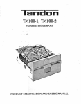
A representative drive is shown in Figure 1-I.
The drive can be mounted in a vertical or
horizontal plane. However, the logic circuit
board must be on the uppermost side when the
drive is mounted horizontally.
The drives are fully self-contained, and require
no opera tor intervention during normal
operation. Each drive consists of electronics to
generate and interpret control signals, a head
positioning system, a read/write system, and a
spindle drive system.
The spindle is belt driven by a D. C. motor with
an integral tachometer. The servo control
circuit and tachometer control the speed of the
spindle.
When the front latch is opened, access is
provided for insertion of a diskette. The diskette
is held in place by plastic guide rails. Its location
is ensured when the diskette is inserted until a
back stop is encountered.
The read/write head assembly is positioned by a
split band positioner mounted to a stepper
motor. The read/write head(s) is a glass-bonded,
ferrite/ceramic structure with a life expectancy
of 20,000 operating hours.
Closing the front latch activates the cone
clamping mechanism, resulting in accurate
centering and clamping of the diskette. The
drive hub is held at a constant speed of 300 RPM
by a servo-controlled D. C. motor. The heads
remain in contact with the recording media
until the front latch is opened;
The electronic components of the drive are
mounted on two printed circuit boards. The logic
circuit board is mounted above the chassis. The
spindle motor control circuit board is mounted
at the rear of the chassis. Power and interface
signals are routed through connectors plugged
directly into the logic circuit board.
The heads are positioned over the desired track
by means of a four-phase stepper motorlband
1-2
D.C. DRIVE MOTOR
LOGIC CIRCUIT BOARD
READ/WRITE HEAD
ASSEMBLY
RESISTOR ARRAY
FRONT PANEL
STEPPER MOTOR
DRIVE CHASSIS
CONE ASSEMBLY
FIGURE 1-1
DISK DRIVE
1-3
SPINDLE ASSEMBLY
SECTION 2
PRODUCT SPECIFICATIONS
INTRODUCTION
This section contains the mechanical, electrical reliability, and environmental specifications for the
TM100-1 and TM100-2drives.
2.1
MECHANICAL SPECIFICATIONS
The physical dimensions of the drive are located in Figure 2-1.
2.2
ELECTRICAL AND OPERATIONAL SPECIFICATIONS
The electrical and operational specifications are located in Table 2-1.
2.3
RELIABILITY SPECIFICATIONS
The reliability specifications are located in Table 2-2.
2.4
ENVIRONMENTAL SPECIFICATIONS
The environmental specifications are located in Table 2-3.
Ia n
aD n
179022-001
CORPORATION, CHATSWORTH, CALIFORNIA 91311
2-1
REV.B
~----(1465~55MM)---~
1E----(139~i~MM)----~
0.B6
(21.84MM)
0.06
(1.52MM)
SERVO
CIRCUIT
BOARD
(203.20MM)
8.00
r
n
....--_~:I
r-
LOGIC
CIRCUIT
BOARD
7.75
(196.85MM)
3.12
(7925 MM)
1.87
(47.50MM)
1.87
(47.50MM)
r(----
JI
0.19
(4.83MM)
0.29
(7.37 MM)
58
(149 i JMM)
I
I
I
I~
3.38
(85.85MM)
I
~
3.38
(85.85 MM)
'----+-_'---_-----'J
NOTES: 1. DIMENSIONS ARE GIVEN IN INCHES. METRIC EQUIVALENTS ARE IN PARENTHESES.
2. TOLERANCE ON ALL DIMENSIONS ±O.020 INCH, UNLESS OTHERWISE SPECIFIED.
3. WEIGHT IS APPROXIMATELY 3 POUNDS (1.35 KILOGRAMS).
FIGURE 2-1
DISK DRIVE OUTLINE DRAWING
lani:lon
179022-001
CORPORATION, CHATSWORTH, CALIFORNIA 91311
2-2
REV.B
TABLE 2-1
ELECTRICAL AND OPERATIONAL SPECIFICATIONS
Media
ANSI-compatible, 5-1/4-inch diskette
Media Life (for reference only)
4 x 10 passes per track
Tracks Per Inch
48 TPI, both drives
6
Tracks Per Drive
TM100-1
40 tracks
TM100-2
80 tracks
Track Spacing
0.529 millimeters, 20.8 milinches
Head Life
20,000 media contact hours
Disk Rotational Speed
300 RPM ± 1.5 percent
Average Rotational Latency
100 milliseconds
Instantaneous Speed Variation (ISV)
±3percent
Motor Start Time
250 milliseconds, maximum
Motor Stop Time
150 milliseconds, maximum
Seek Time, track-to-track
5 milliseconds
Head Settling Time
15 milliseconds
Average Track Access Time,
including head settling time
75 milliseconds
Typical Recording Modes
FM, MFM, MMFM
Data Transfer Rate
250,000 bits per second, double density
Flux Reversals Per Inch (FRPI),
inside track
Both Models, Side 0
5,535FRPI
TM100-2, Side 1
5,877FRPI
Ia n
aD n
CORPORATION, CHATSWORTH, CALIFORNIA 91311
2-3
179022-001
REV.B
TABLE 2-1 (CONTINUED)
ELECTRICAL AND OPERATIONAL SPECIFICATIONS
Unformatted Recording Capacity
TM100-1
250 kilobytes per disk
TM100-2
500 kilobytes per disk
D. C. Voltage and Current
Requirements
+ 12 volts D. C. Power
+ 12 volts ± 0.6 volt, 900 milliamperes,
average, 100 millivolts peak-to-peak
ripple.
+5 volts D. C. Power
+ 5 volts ± 0.25 volt, 600 milliamperes,
average, with less than 100 millivolts
peak-to-peak ripple.
When prepared for shipment by Tandon,
the drive meets the requirements of
NSTA preshipment test procedure Project
1A.
Shipment
TABLE 2-2
RELIABILITY SPECIFICATIONS
Error Rates, maximum, exclusive of
external sources, e.g.: electronics,
defective and contaminated diskettes
Soft Errors {Recoverable}
12
Hard Errors {Nonrecoverable}
One in 10 bits
Seek Errors
One in 10 seeks
6
Mean Time Between Failures
8,000 hours, 25 percent duty cycle
Mean Time To Repair
30 minutes
Ia n
aD n
CORPORATION, CHATSWORTH, CALIFORNIA 91311
2-4
179022-001
REV.B
TABLE 2-3
ENVIRONMENTAL SPECIFICATIONS
Temperature
Operating, media dependent
10°C to 46°C, 50°F to 115°F
Nonoperating
-40°C to 71 °c, -40°F to 160°F
Relative Humidity
Operating, noncondensing,
media dependent
20-to-80 percent
Nonoperating, noncondensing
5-to-95 percent
Altitude
152.4 meters, 500 feet, below sea level, to
15,240 meters, 50,000 feet, above sea level
Operating or nonoperating
Ia n
aD n
CORPORATION, CHATSWORTH, CALIFORNIA 91311
2-5
179022-001
REV.B
SECTION 3
OPERATION
INTRODUCTION
3. Remove the cardboard shipping insert,
and retain for future shipment.
This section contains information on how to
unpack, check out, install, and operate the
TMIOO-l and TMI00-2 drives.
4. Ensure the front panel is secure.
3.1
5. Ensure the drive belt is in place.
6. Manually rotate the drive hub. It should
rotate freely.
UNPACKING THE DRIVE
7. Ensure both circuit boards are secure.
The drives are packaged in protective containers
to minimize the possibility of damage during
shipment. The following list is the recommended
procedure for unpacking the drive.
8. Ensure the connectors are firmly seated.
3.3
1. Place the container on a flat work
surface.
MOUNTING THE DRIVE
2. Remove the upper half of the container.
The drive has been designed to be mounted horizontally or vertically. When mounted horizontally, the logic circuit board side of the drive
must be the top side.
3. Remove the drive from the lower half of
the container.
4. Check the contents of the container
against the packing slip.
Four 6-32 tapped mounting holes are provided
on the bottom of the drive, and two 6-32 tapped
mounting holes on each side, for attachment to
user-supplied mounting brackets. When installed in either plane, horizontal or vertical,
only two mounting screws are required to securely hold the drive in place.
5. Investigate the contents of the container
for possible damage.
6. Notify the carrier immediately if any
damage is found.
3.2
Any mounting scheme in which the drive is part
of the structural integrity of the enclosure is not
permitted. Mounting schemes should allow for
adjustable brackets or incorporate resilient
members to accommodate tolerances. In addition, it is recommended that mounting schemes
include no more than two mounting surfaces.
PREINSTALLATION
CHECKOUT
Before applying power to the drive, the following
inspection should be conducted:
1. Check to ensure the front latch opens
and closes.
The drive is manufactured and tested with some
critical internal alignments that must be
maintained. Hence, it is important that the
mounting hardware not introduce significant
stress on the chassis.
2. When the latch is moved to an open position' the head arm raises.
3-1
DUST COVER
TABLE 3-1
DRIVE INTERFACE LINES
AND PIN ASSIGNMENTS
The design of an enclosure should incorporate a
means to prevent contamination from loose
items, e.g., dust, lint, and paper chad, since the
drive does not have a dust cover.
Input Control Lines:
Controller-To-Disk Drive
Ground
Pin
Signal
1
3
5
9
11
13
15
17
19
21
23
31
2
4
6
10
12
14
16
18
20
22
24
32
Connector Clamp
Spare
Drive Select 3
Drive Select 0
Drive Select 1
Drive Select 2
Motor On
Direction Select
Step
Composite Write Data
Write Enable
Side Select
COOLING
Heat dissipation from a single drive is normally
15 watts, 51 BTU per hour, under high load conditions. When the drive is mounted so the components have access to a free flow of air, normal
convection cooling allows operation within the
specified temperature range.
When the drive is mounted in a confined environment, air flow must be provided to maintain
specified air temperatures in the vicinity of the
motors, printed circuit board, and diskettes.
Output Control Lines:
Disk Drive-To-Controller
When forced air is used, air flow must be directed outward from the drive. Do not intake air
through the drive or heads and diskettes.
3.4
INTERFACE CONNECTIONS
Ground
Pin
Signal
7
25
27
29
33
8
26
28
30
34
Index/Sector
Track 0
Write Protect
Composite Read Data
Spare
Interface connections for the TMI00-l and
TMI00-2 are made via a user-supplied, thirtyfour pin, flat ribbon connector, 3M Part Number
3463-0001 or Amp Part Number 583717-5, using
contact Part Number 1-583616-1 for twisted
pair or its equivalent. This connector mates
directly with the circuit board connector at the
rear of the drive. The D. C. power connector is a
four-pin connector at the rear of the drive. The
interface description of the connectors, and the
location of each one, is contained in this section.
Interface lines are located in Table 3-1. D. C.
power connector pin assignments are located in
Table 3-2.
The Drive Select lines provide a means of selecting and deselecting a drive. These four lines
select one of the four drives attached to the
controller.
The signal wire harness should be of the flat
ribbon or twisted pair type, 26-to-28 gauge
conductor, compatible with the connector to be
used. The recommended cable length is ten feet
maximum.
When the signal logic level is true Oow) , the
drive electronics are activated, and the drive is
conditioned to respond to Step or Read/Write
commands. A Drive Select line must remain
stable in the true Qow) state until a Step or
INPUT CONTROL LINES
DRIVE SELECT LINES
3-2
Read/Write command is completed. When the
signal line logic level is false Origh), the input
control lines and output status lines are disabled.
The drive electronics ignore step pulses when
one of three conditions exists:
1. The write enable is true Qow).
The drive address is determined by a jumper
select on the logic circuit board. Drive Select
lines 0 through 3 provide a means of daisy chaining a maximum of four drives to a controller.
Only one can be true Qow) at a time. An undefined operation results if two or more drives are
assigned the same address or if two or more
Drive Select lines are in the true Qow) state
simultaneously.
2. The direction select is false Origh), and
the head is positioned at Track O.
3. The drive is not selected.
COMPOSITE WRITE DATA
When the drive is selected, this interface line
provides the bit serial composite write data
pulses that control the switching of the write
current in the selected head. The write electronics must be conditioned for writing by the
Write Enable line.
MOTOR ON
When this signal is true Qow), the drive motor
accelerates to its nominal speed of 300 RPM,
and stabilizes at this speed in less than 250
milliseconds. When the signal line logic level
goes false Origh), the drive decelerates to a stop.
This signal is not gated with Drive Select.
For each high-to-Iow transition on the Composite
Write Data line, a flux change is produced at the
write head gap. This causes a flux change to be
recorded on the media.
When a single-density (FM) type encoding technique is used in which data and clock form the
combined Write Data signal, it is recommended
that the repetition of the high-to-Iow transitions, while writing all zeros, be equal to one-half
the maximum data rate, 125 kilohertz + 0.1
percent, and the repetition of the high-to-Iow
transitions, when writing all ones, be equal to
the maximum data rate, 250 kilohertz +0.1
percent.
The motor activates momentarily when the
front latch is closed. This motor start function
remains active for approximately five seconds,
unless Motor On is in the true Qow) condition.
DIRECTION SELECT AND STEP LINES
(TWO LINES)
When the drive is selected, a true Qow) pulse on
the Step line, with a time duration greater than
200 nanoseconds, initiates the access motion.
The direction of motion is determined by the
logic state of the Direction Select line when a
step pulse is issued. The motion is toward the
center of the disk if the Direction Select line is
in the true Oow) state. The direction of motion is
away from the center of the disk if the Direction
Select line is in the false Origh) state.
Host controllers may implement write precompensation circuits that recognize worst case patterns and adjust the write data waveform.
Although a value cannot be specified for write
precompensation, Tandon suggests a value of
250 nanoseconds for systems using MFM double
density recording format.
WRITE ENABLE
To ensure proper positioning, the Direction
Select line should be stable at least 100 nanoseconds prior to issuing a corresponding step pulse,
and remain true Qow) 100 nanoseconds after it.
When this signal is true Qow) , the write
electronics are prepared for writing data and
the read electronics are disabled. This signal
turns on write current in the selected read/write
head. Data is written under the control of the
Composite Write Data and Side Select input
lines. When the Write Enable line is false
Origh) , all write electronics are disabled.
The access motion is initiated on the trailing
edge of the step pulse. The time period between
consecutive trailing edges of step pulses should
be not less than five milliseconds.
3-3
When a write protected diskette is installed in a
drive, the write electronics are disabled, irrespective of the state of the Write Enable or Side
Select lines.
WRITE PROTECT
When the Write Protect line goes true Qow), the
diskette is write protected and the write
electronics are disabled. It is recommended the
controller not issue a Write command when the
Write Protect signal is true Qow).
SIDE SELECT, TM100-2
The Side Select interface line defines which side
of a two-sided diskette is used for data transfer.
When the Write Protect line is false Origh), the
write electronics can be enabled.
A false Origh) level on this line selects the
read/write head on side zero, the lower head, of
the drive. A true Qow) level on this line selects
the read/write head on side one, the upper head
of the drive.
COMPOSITE READ DATA
This interface line transmits the readback data
to the controller when the drive is selected.
It provides a pulse for each flux transition detected from the diskette. The Composite Read
Data output line goes true Qow) for a duration
of 1 + 0.25 microseconds for each flux change
detected from the diskette.
OUTPUT CONTROL LINES
INDEX/SECTOR
The index/sector signal is a composite of the
index pulse and sector signals.
The leading edge of the Composite Read Data
output pulse represents the true position of the
flux transitions on the diskette's surface.
An index pulse is provided once every revolution, 200 milliseconds nominal, to indicate the
beginning of a track to the controller. The leading edge of this signal must always be used to
ensure timing accuracy. The index/sector line remains in the true Qow) state for the duration of
the index pulse, which is nominally four
milliseconds.
TYPICAL INTERFACE
CHARACTERISTICS
Lines between the controller and the drive have
the following characteristics:
The sector signal portion appears only when
using hard sectored diskettes.
Vout True
= + 0.4 volt maximum at lout
= 48 milliamperes, maximum
TRACK 0
Vout False =
+ 2.4 volts minim urn open
collector at lout = 250
microamperes,m~mum
When the drive is selected, the Track 0 interface
signal, when true Qow), indicates to the controller that the read/write head(s) are positioned at
Track O. This signal remains true Qow) until the
heads are moved from Track O.
Figure 3-1 contains the characteristics of the
electrical interface. Figure 3-2 contains the control and data timing requirements.
3-4
+5 VOLTS
150 OHMS
r-------l
I
+TRUE
I
I
+TRUE
I
-
I
L EQUIVALEN~
I
I I
I 74380R
__
TRANSMISSION
LINE :iii 10 FEET
J
I
I
I
I
I
-
I RECEIVER
I
DRIVER
FIGURE 3-1
ELECTRICAL INTERFACE CHARACTERISTICS
3.5
D. C. POWER
The chassis should be connected to earth ground
to ensure proper operation. The conductor
should be lS-to-18 AWG, minimum.
D. c. power is supplied to the drive via a four-pin
AMP connector, J2, mounted on the circuit
board. The mating connector, not supplied, is
AMP Part Number 1-480424-0, using AMP contact Part Number SOS191-1. Pin assignments
are found in Table 3-2. The conductor should be
lS-to-18 AWG, minimum.
3.6
The drive address and option patching is determined by the programmable shunt located at IE
on the logic circuit board. The DSO through DS3
jumpers determine the drive address. The MX
jumper is used only in single drive systems. See
Figure 3-3.
TABLE 3-2
D. C. POWER CONNECTOR
PIN ASSIGNMENTS
Pin
Supply Voltage
1
2
3
4
+ 12 volts D. C.
Pin
Ground lug 3/1S-inch
quick disconnect
DRIVE ADDRESS AND
OPTION PATCHING
The program shunt is AMP Part Number
435704-7. The shunt positions can be cut using
AMP's tool, Part Number 435705. The shunt is
installed in a DIP socket. At the user's option, it
can be removed and replaced by a DIP switch.
12 volts return
5 volts return
+ 5 volts D. C.
DSO THROUGH DS3 JUMPERS
When daisy chaining two or more drives to a
controller, the Drive Select (DS) jumpers patch
the drive select control signal to enable the logic
of the proper drive. Normally, all the shunt
jumpers would be cut, except for the DS jumper
Signal
Chassis ground from
controller
3-5
_,----------------------------------~I~S------------
POWER ON
--1
DRIVE SELECT
t.--- 1MINIMUM
00 MILLISECONDS
I
~--------------------------~JS~------------
~~~~~~----------------------~s~s-----------
MOTOR ON
±3
It+- MILLISECONDS
250 MILLISECONDS ~
MAXIMUM
200
I
1
INDEX----------------------~LJ
LJ-----~'S
-..J I--
500 NANOSECONDS ~
MAXIMUM
I
r-
500NANOSECONDS~
~r-------------------------~'S
4 MILLISECONDS'
------------------1.
TRACK 0
MAXIMUM
- I
WRITE PROTECT --------------~I
------------------------~s f~-----------
------------.
. .,. J
--J
SIDE SELECT
100 NANOSECONDS ,-----. MINIMUM
~
DIRECTION
r-
----------------------4, ...s ------
5 MILLISECONDS--.I
MINIMUM
200 NANOSECONDS --J
__________________M_I_N_IM_U_M_____
~
I
STEP
100NANOSECONDS~
~
MINIMUM
t.-
I--
J.--1
~
I
I
,-
MINIMUM
I
r
S~
=::;f.
I
I ~
900 MICROSECONDS*--.f
I
390 MICROSECONDS*~ I-------------------------~I--------------~
ERASE GATE
I
(TUNNEL ERASE)
200 NANOSECONDS
MINIMUM
,__- - - - - - -
LJ
20 MILLISECONDS
MAXIMUM
I . - 250 MILLISECONDS
WRITE ENABLE
100
NANOSECONDS1
MINIMUM
.1
Id
I 2100 NANOSECONDS
j.--
I
I~----~I ~S----~I------~ 4 MICROSECONDS
I I
WRITE~~-------10-0-M--IC-R-O-S-E-C-O-N-D-S--~~t--r-----------~~
I MAXIMUM
rDATA--------------------I-~ ~ S"""-------MINIMUM
4 MICROSECONDS
READ
250 MILLISECONDS
MINIMUM
-.II
I
J- L
-1
~
L
r - 8 MICROSECONDS
~I IJ4- 1± MICROSECOND
250 NANOSECONDS
8 MICROSECONDS
*FOR REFERENCE ONLY
FIGURE 3-2
CONTROL AND DATA TIMING REQUIREMENTS
3-6
that addresses each individual drive in the daisy
chain. The terminator resistor pack, RPl,
located on the logic circuit board should be installed in the last drive of the daisy chain. All
other drives on the interface must have the
resistor pack removed.
WRITE FLIP-FLOP CONTROL
(W2, W3)
W2 and W3 control the set and preset lines of
the write flip-flop, IC-5C. W2 is installed for the
standard configuration, W3 is for special use.
MX JUMPER
W2
W3
x
The Multiplex (MX) jumper is used only in
single drive systems when the user requires the
drive logics to be enabled at all times. If the
drive is not selected through the DSjumper, and
the MX jumper is not cut, the drive logics are
enabled but the front panel L.E.D. is not on. The
MX jumper must be cut in a multiple drive
system.
x
WRITE FLIP-FLOP
CONTROL
Disables set and preset lines
on the write flip-flop only
during internal N Write.
Disables set and preset lines
on the write flip-flop
continuously.
WRITE PROTECT CONTROL (W4, W5)
HS AND HM JUMPERS
Write Protect Control from the write protect
switch is disabled with W5 installed. Standard
Write Protect Control is enabled with W4
installed.
HS and HM jumpers are not used, and must be
cut.
POWER SAVE OPTION
W4
When shipped from the factory, the drive is configured with a jumper at R5l, 0 ohm resistor, for
the TMlOO-l and TMlOO-2 drives. R5l maintains 200 milliamperes of current to the stepper
motor whether or not the drive is selected. Maintaining power to this motor prevents the head
carriage from moving when the drive is not
selected. The jumper at R5l may be moved to
position R50, which removes the power to the
stepper motor when the drive is not selected, for
a savings of approximately 3.8 watts per drive.
When R50 is used, the user must ensure the
track location when the drive is reselected.
W5
x
x
WRITE PROTECT
CONTROL
Write Protect Control
responds to a write protected
diskette.
Write Protect Control is
inhibited.
ACTIVITY L.E.D. CONTROL
(W6, W7, W9)
The Activity L.E.D. may be illuminated by an
optional input line, Jl-4 (N In Use). Normally,
the Activity L.E.D. is controlled with Drive
Select, W6 installed.
SIDE SELECT (W1)
W6
For use in double-sided drives:
W7
W9
x
Wl
x
SIDE SELECT
For use in single-sided drives,
TMlOO-l.
For use in double-sided drives,
TMlOO-2.
Activity L.E.D. is
controlled with Drive
Select.
X
3-7
ACTIVITY L. E. D.
CONTROL
X
Activity L.E.D. is
controlled with N In
Use, Jl-4.
o
o
W5000W4
R51
oCJo
OR50o
PROGRAMMABLE
SHUNT SOCKET (1 E)
TERMINATOR
SOCKET (2F)
LOGIC CIRCUIT BOARD
1
HS NOT USED
18
2
DSO
15
3
DS1
14
4
DS2
13
5
DS3
12
8
MX
11
7
SPARE
10
8
HM NOT USED
9
PROGRAMMABLE SHUNT SOCKET 1 E
FIGURE 3-3
LOGIC BOARD WITH PROGRAMMABLE SHUNTS AND OPTION PATCHING LOCATIONS
3-8
CAUTION
DRIVE SELECT 3 ENABLE (W8)
Damage to the center of;· the
diskette may result if the door is
closed when the diskette is not
properly inserted. This prevents
reliable recovery of the recorded
data.
Removal of this jumper allows interface JI-6 to
be used as an alternate input/output line. W8 is
normally installed.
W8
X
DRIVE SELECT 3 ENABLE
Allows drive to be selected via JI-6.
Disables Drive Select 3 line.
WRITE PROTECT TAB
DOOR LOCK SOLENOID (W10)
The drive is equipped with a write protect
switch assembly. This switch operates in
conjunction with a diskette that has a slot cut in
the protective jacket. Figure 3-5 contains the
location of the slot.
This jumper is used in conjunction with an
optional door lock solenoid. The WIO jumper is
normally not installed.
WIO
X
3.7
When the slot is covered with an optically
opaque, self-adhesive tab, the diskette is write
protected. The tab must be removed to write on
the diskette. Figure 3-5 contains information on
how to install a tab to cover the slot.
DOOR LOCK SOLENOID
Enables door lock solenoid via JI-2.
Disables door lock circuits.
DISKETTES
DISKETTE HANDLING AND STORAGE
The TMIOO-I and TMIOO-2 drives use an
ANSI-compatible, 5-1/4-inch diskette. Diskettes
are available with a single index hole or with
multiple (index and sector) holes.
It is important the diskette be handled and
stored correctly so the integrity of the recorded
data is maintained. A damaged or contaminated
diskette can impair or prevent recovery of data,
and can result in damage to the read/write
head (s).
Diskettes with a single hole are used when soft
sector format is required. Multiple hole
diskettes provide sector information through
the use of an index sensor and electronics.
Figure 3-5 contains an illustration of the
physical configuration of the diskette. The
5.I25-inch diskette is oxide-coated, flexible
mylar. It is enclosed in a 5-1/4-inch square
protective jacket. Read/write head access is
made through an aperture in the jacket. In addition, openings for the drive hub and diskette
index hole are provided.
Figure 3-4 illustrates the diskette used with the
drive. This recording media is a flexible diskette
enclosed in a protective jacket. The protected
diskette, free to rotate within the jacket, is
continuously cleaned by its soft fabric lining
during normal operation.
Figure 3-6 provides some helpful hints on the
care and handling of the drive and diskettes. In .
addition, to ensure trouble-free operation and to
enhance the service life of the diskette, the
following handling procedures should be
observed.
LOADING THE DISKETTE
The drive is loaded by inserting the diskette,
head aperture forward, into the front slot of the
drive. Access to the diskette loading slot is
obtained by opening the front latch.
1. Return the diskette to the protective
jacket when not in use.
The diskette should be carefully inserted until it
is solidly against the back stop.
2. Avoid exposing the diskette to any
magnetizing force in excess of 50 oersted.
3-9
3. To avoid warping, do not store the
diskette in direct sunlight.
NOTE
The 50-oersted level magnetizing
force is reached at a distance of
approximately three inches from
a typical source, e.g., motors, generators, or transformers.
4. Do not use a lead pencil or a ballpoint
pen to write on the label. Use a felt
tipped pen, and mark lightly on the label.
rJ
3.56 MM
(0.14INCH)
I----~-__+_t
133.4 MM
(5.25 INCH)
L
SEALED
PROTECTIVE
JACKET
++----+-
L
r
133.4MM
(5.25 INCH)
133.4 MM
(5.25 INCH)
6.30 ± 0.25 MM
(0.25 " 0.01 INCH)
r
96.5 ± 0.25 MM
(3.80 ± 0.01 INCH)
J
l
SPINDLE
ACCESS HOLE
LINER
HEAD
APERTURE
FIGURE3-4
RECORDING MEDIA
3-10
WRITE PROTECT TAB
' - WRITE PROTECT TAB
FOLD OVER BACK OF DISKETTE
r
3.56 MM
(0.14 INCH)
.---------4-.J
6.30 MM
(0.25 INCH)
96.5 MM
(3.808 INCHES)
l
INDEX ACCESS HOLE
FIGURE 3-5
WRITE PROTECT TAB
3-11
DO NOT WRITE ON THE
JACKET WITH PEN OR
PENCIL. USE A FELT
TIPPED PEN.
TO AVOID DAMAGE TO
THE DISKETTE AND TO
YOUR DRIVE, INSERT
DISKETTE CAREFULLY
UNTIL THE BACKSTOP
IS ENCOUNTERED.
DO NOT TOUCH PRECISION SURFACE WITH
YOUR FINGERS.
KEEP THE DISKETTE
AWAY FROM MAGNETIC FIELDS.
DISKETTES SHOULD
BE STORED AT
10°C to 52°C
50°F to 125°F
HANDLE WITH CARE;
BENDING AND FOLDING MAY DAMAGE
DISKETTE.
FIGURE 3-6
DISKETTE HANDLING AND STORAGE
3-12
RETURN THE DISKETTE
TO ITS JACKET WHEN
NOT IN USE.
SECTION 4
THEORY OF OPERATION
INTRODUCTION
Recording of data on a magnetic medium is
based on the principles of electromagnetics.
When current flows in a coil of wire it produces
a magnetic field. The field is confined in a core
of magnetic material around which the wire is
wound. A narrow slot, called the air gap, is
placed in the core located closest to the media. It
is the magnetic field in the vicinity of the air
gap that magnetizes the magnetic medium (Figure 4-1). When the current is reversed, the
polarity of magnetization is reversed.
This section contains a description on the theory
of operation of the drive. The discussion begins
with a general summary of magnetic data recording, followed by a description of each major
function of the drive.
Circuit block diagrams and schematics are located in the appendices. They are useful to show
the interconnections between the electronic circuits and the mechanical components.
4.1
Information can be recorded on the diskette by
using a double-frequency code. The magnetization profiles in each bit cell for the number sequence shown for FM recording are shown in
Figure 4-2.
DATA RECORDING
When data is read, the same head that writes
the data is used. The data stored is a digital bit
representing a 0 or 1. In each bit cell, the first
flux reversal represents a clock bit. A second
reversal represents a stored bit 1. The absence of
a second reversal represents a bit o.
Digital information is represented by a sequence
of bits: either 0 or 1. Small areas of the medium
in which such binary information is stored, for
example the iron oxide coating of a magnetic
disk, must be put in one state or the other to represent the data.
- - - - ELECTROMAGNETIC CORE
MAGNETIC FIELD OF HEAD
~ ----'~
MAGNETIC FIELD OF MEDIA
ELECTRIC _ _ __ _
CURRENT
~
..
ROTATION OF MEDIA
FIGURE 4-1
ELECTROMAGNETIC CORE
4-1
-.f BIT CELLI+BIT PATTERN
I
I
I
I
!
I
I
I
!
WRITE DATA
I
I
I
I
MAGNETIZATION
H
H
I
I
I
I
I
I
I
I
PI
~
I I!
f:
I
~
I
=rHO
! I
! I
I
0
I
if
~
\a
P;C::
I:
!
I
MAGNETIC ELEMENTS
N
I
I
I
I
I
I
I
I
I
I
I
I
I
I
I
I
I
I
I
I
I
I
I
I
I
I
I
I
I
I
I
I
I
I
I
I
I
I
I
I
I
I
I
I
I
FIGURE 4-2
FM RECORDING MAGNETIZATION PROFILES
The comparator and the digitizer circuitry generate a one microsecond Read Data pulse, corresponding to each peak of the Read signal. Then,
the composite read data signal is sent to the user
system via the Read Data interface line.
As the disk spins, the magnetic fields of the
stored data pass successively under the head.
The changing fields induce, in the head, an A. C.
voltage signal which is then amplified and
filtered, differentiated, and digitized (Figure
4-3).
LINEAR OUTPUT FROM FILTER
OUTPUT FROM DIFFERENTIATOR
I
I
I
u-ir
READ DATA INTERFACE
I
I
FIGURE 4-3
READ TIMING DIAGRAM
4-2
I
I
4.2
WRITE PROTECT SWITCH
COMPONENTS OF THE
DRIVE
The Write Protect signal is derived from a mechanical switch integrated into the drive, the
switch is deactivated, causing a high signal on
J4, Pin 5. Then, it is buffered and inverted to disable the Write Enable signal. It is also gated
with drive select, producing an output signal on
the interface.
The drive contains the electrical and mechanical
components required to perform four major
functions:
1. Generate and interpret control signals.
2. Position the read/write head(s) to the
desired track.
3. Write and read data.
TRACK 0 SWITCH
4. Control the spindle.
The electrical and mechanical components of
the drive are connected together via four- and
five-pin connectors. This allows the individual
assemblies to be removed (Figure 4-4).
4.3
The Track 0 sensor signal is derived from a mechanical switch internal to the drive. As the
head carriage moves back toward Track 0, the
switch is activated between Tracks 0 and 3.
This low active signal comes in via Connector
P11, Pin 1, and is supplied to a latch that
debounces the switch noise (Figure 4-6). The
combination of the Track 0 switch being activated and the proper stepper motor phase (Phase 0)
produces all high signals at Ie 4B, pins 9, 10, 12,
and 13, causing a low output at Ie 4B, Pin 8
(Test Point 8). Then, this signal is buffered
through Ie 3D, Pins 1 and 2, which inhibits stepping to Track 0 minus 1. Ie IF Pins 11, 12, and
13 gate the Track 0 output with Drive Select, to
give a Track 0 output to Pin 26 of the interface.
GENERATE AND
INTERPRET CONTROL
SIGNALS
The components of the drive required to generate and interpret the control signals are:
1. Index Sensor
2. Write Protect Switch
3. Track 0 Switch
4. Drive Select
DRIVE SELECT
INDEX SENSOR
The Drive Select signal is derived from the host
controller through the interface connector.
The Index signal is derived from an infrared
L.E.D. and phototransistor detector. When the
index/sector hole in the diskette passes through
the index sensor, the light from the L.E.D. is allowed to turn on the index detector, producing a
positive pulse on J4, Pin 15 (Figure 4-5).
R14 holds the output of the appropriate select
line high until the line is driven low. This signal
is buffered through Ie 3E and Ie 3D, which enables the drive electronics.
The front panel L.E.D. is driven by the select
logic through Ie 3E, Pins 3 to 4. If the drive is
not selected through the select jumpers, and the
MX jumper is not cut, the drive electronics are
active but the front panel L.E.D. is not on.
This signal is shaped by an input buffer, Q8, and
supplied to inverter Ie 2E. Then, it is gated with
Drive Select for an output control signal at the
interface J1, Pin 8.
4-3
HEAD 1
HEAD 0
INDEX EMITTER
WRITE
PROTECT SWITCH
INDEX SENSOR
STEPPER MOTOR
NOT USED
TRACK 0 SWITCH
ACTIVITY L.E.D.
P6
POWER
J2
(1-4)
J3
P5
J4
(5-8)
J4
P10 (13-16)
J4
P12 (23-27)
J4
P7 (1-4)
J4
P11 (19-22)
J4
P9 (10-13)
J4
(28-31 )
P8
CONTROL
AND
READ
WRITE
CIRCUIT
BOARD
I/O
INTERFACE
J1
(1-34)
PIN9 }
PIN 18 J4
PIN32
CIRCUIT
BOARD
JUMPER
CABLE
J1
P20 (7-10)
DRIVE MOTOR
PIN 6 REMOVED
0
(0-10)
SERVO
CIRCUIT BOARD
DRIVE MOTOR
J1
L - - - - - - - - - - - - - - t P21 (0-5)
________________
L--~~
FIGURE 4-4
INTERCONNECT BLOCK DIAGRAM
4-4
~
4.4
flop to be toggled, is accomplished by the two exclusive OR gates of IC 5D. These gates are controlled by the Step direction line and by the
state of the two flip flop outputs.
READ/WRITE HEAD
POSITIONER
The components of the drive required to position
the read/write head(s) at the desired track are:
Test Point 8 is low when the carriage is positioned at Track 0 and the stepper motor is at
Phase O. When stepping in or out, Test Point 12
is a high going pulse for each step of the carriage
(Table 4-1).
1. Step and direction circuits
2. Stepper motor control circuits
3. Stepper motor
STEPPER MOTOR CONTROL
STEP AND DIRECTION
The stepper motor control circuits generate the
four phases of the step sequence based on information from the step and direction inputs.
These four phases are fed to the stepper motor
drivers, which produce the current through the
motor's coils.
The Step and Direction signals are derived from
the host controller via interface connector J1,
Pin 20, and J1, Pin 18, respectively.
The direction line sets the proper phase to
the exclusive OR gates of IC 5D. This signal is
also buffered by IC 3D to gate IC 4F to inhibit
stepping outward when the drive is already at
TrackO.
STEPPER MOTOR
The step pulses are buffered by 2E, and gated at
IC 4B by the unit select, the N Write signal
(false), and by the outward step inhibit of the
Track 0 signal. Then, the step pulses go to the
clock inputs of the two flip flops at IC 4C. The direction of the step, hence the selection of the flip
The stepper motor is a unipolar, four-phase
motor, which rotates 3.6 degrees for each phase
(Table 4-1). The capstan and split band translates this rotation to a one track linear movement of the head carriage assembly.
TABLE 4-1
STEPPER LOGIC TRUTH TABLE
Step In Toward The Inner Tracks
Step Out Toward Track 0
Pin
Number
Phase
Pin
Number
Phase
0
1
2
3
0
4C-5
0
0
1
1
0
1
4C-6
1
1
0
0
1
1
0
4C-9
0
1
1
0
0
0
1
4C-8
1
0
0
1
1
0
3
2
1
0
4C-5
0
1
1
0
0
4C-6
1
0
0
1
4C-9
0
0
1
4C-8
1
1
0
4-5
1.--4 MILLISECONDS AVERAGE
......- - - - - - - 2 0 0 MILLISECONDS-------~
FIGURE 4-5
SOFT-SECTORED INDEX PULSE
r--------- +5 VOLTS
TRACK 0, TEST POINT 8
_______10 VOLT
rSVOLTS
TRACK 0 ADJUSTMENT MONITOR POINT
IC 4B,PIN9
~·----------------OVOU
TRACKS
-6
ON
DISKETTE
STEPPER
MOTOR
PHASES
2
-5
-4
-3
-2
-1
0
+1
+2
+3
+4
+5
+6
3
0
1
2
3
0
1
2
3
0
1
2
FIGURE 4-6
TRACK 0 TIMING
4-6
4.5
READ/WRITE DATA
WRITE/ERASE CIRCUITS
The write electronics consist of a write current
source, a write waveform generator, an erase
current source, the trim erase control logic, and
the side select logic (Figure 4-7).
The components of the drive required to read
and write'data are:
1. Read/Write Head Assembly
The signals required to control the data electronics provided by the host controller are:
2. Side Select circuits
3. WritelErase circuits
1. Drive Select
4. Read Data circuits
2. Write Enable
3. Write Data
READ/WRITE HEAD ASSEMBLY
4. Side Select
The read/write head(s) are glass bonded, ferrite
cores mounted in a ceramic structure. The lower
head structure is mounted in a fixed position to
a plastic carriage. The upper head is mounted to
a gimballed flexure to conform to the diskette.
The winding on the head is center tapped.
During a write operation, current from the write
current source flows in alternate halves of the
winding, under control of the write waveform
generator.
The head carriage assembly is attached to the
chassis on guide rails. It is positioned by a split
band attached to the stepper motor.
When the drive is selected and write protect is
false, N Write Enable initiates the write logic.
Seven events that occur are (Figures 4-7 and
4-8):
1. The pre-erase delay one shot is started,
SIDE SELECT CIRCUITS
390 microseconds.
2. The post-erase delay one shot is started,
900 microseconds.
The Side Select signal is derived from the host
controller via the interface connector J1, Pin 32.
This signal is buffered. If the signal is high at
the interface, Side 0 is selected by applying a
voltage potential on the center tap of Head 0,
and allows current to flow in the coils of Head o.
If the signal at the interface is low, Side 1, is
selected, by applying a voltage potential on the
center tap of Head 1, allowing current to flow in
the coils of Head 1.
3. The post-erase delay one shot outputs a
signal: N Internal Write Busy. It is used
to disable the Read Data output circuit,
and to increase the read/write diode
matrix voltage from 5 volts D. C. to 12
volts D. C. via the side select logic during
a write operation.
4. The write current source is enabled only
when the + 5 volts D. C. supplied to the
drive is at the correct value.
In the read mode, a potential of +5 volts D. C. is
applied to the selected head diode matrix. The
write mode increases the voltage applied to the
selected head diode matrix to + 12 volts D. C.
from the beginning of Write Enable until the
end of Internal Write Busy.
5. The write waveform generator has its
preset and clear inputs set to + 5 volts
D. C. instead of ground.
4-7
N INTERNAL WRITE BUSY - - - - - - - - - - .
SIDE
SELECT 1--------.
LOGIC
SIDE SELECT - - - - - - - - -
WRITE
DRIVER 1
Q
D
WRITE
WAVEFORM
C GENERATOR Q
BUFFER
N WRITE DATA
READ/
WRITE
COILS
>----t----4
WRITE
......--------4. . . .-+--~ DRIVER 2
N WRITE ENABLE
N WRITE PROTECT
DRIVE SELECT
(N WRITE)
ERASE
COIL
WRITE
CURRENT
SOURCE
ERASE
DELAY
LOGIC
1---"""
ERASE
~--4~-~CURRENT~----------------
SOURCE
'---------
FIGURE 4-7
WRITE DATA CIRCUIT BLOCK DIAGRAM
4-8
(N INTERNAL
READ DISABLE
~ AND SIDE
WRITE BUSY)
SELECT LOGIC
NOTE 1
t=O
I
I
I
I
I
I
I
I
I
I
I
I
I
I
II
I
I
I
I
WRITE ENABLE
I
390
MICROSECONDS
i
I
900 MICROSEC~NDS ~
~
TRIM ERASE
I
I
I
INTERNAL
WRITE BUSY
I
I
I
I
I
N WRITE DATA
NOTE 2
I
WRITE
WAVEFORM
GENERATOR
I
14-
I
I~
I
~
I
I
I
I
II
WRITE CURRENT
I
I
I
NOTE4
NOTES:
I--
1. t = 0 = 250 MILLISECONDS AFTER DRIVE MOTOR STARTS OR 20 MILLISECONDS AFTER LAST STEP PULSE,
WHICHEVER IS THE LATEST TIME.
2. UNSYNCHRONIZED
3. 8.5 MILLIAMPERAGE PEAK TO PEAK
4. 4 MICROSECONDS MINIMUM, 8 MICROSECONDS MAXIMUM
FIGURE 4-8
WRITE OPERATION TIMING DIAGRAM
4-9
6. Input diodes to the read amplifier are
reverse biased by N Write to protect the
read amplifier during the write
operation.
The drive must be in a ready condition before
reading can begin. This ready condition must be
established by the user system. In addition to
the requirements established in this section, a
100 microsecond delay must exist from the trailing edge of the Trim Erase signal to allow the
read amplifier to settle after the transient
caused by the Read Only circuit returning to the
Read mode.
7. The write data input is inverted and used
to clock the waveform generator which
selects a write driver, thus providing a
ground to forward bias a diode, allowing
current to flow through the coil.
The output signal from the read/write head is
amplified by a read amplifier, and filtered by a
linear phase filter to remove noise. The linear
output from the filter is passed to the differentiator, whicll generates a waveform whose zero
crossovers correspond to the peaks of the Read
signal, then, this signal is fed to the comparator,
time domain filter, and digitizer circuitry
(Figure 4- 9).
When there is a pre-erase delay 390-microsecond
time out, the erase current source is turned on.
The clocking of the waveform generator during
write operation provides a trigger to the posterase delay one shot, and does not allow it to
time out until all data is written.
4.6
N Internal Write Busy is active until the end of
the post-erase delay, and keeps + 12 volts D. C.
on the read/write diode matrix during the erase
time.
SPINDLE CONTROL
The components of the drive required to control
the spindle are:
The duration of a write operation is from the
true going edge of Write Enable to the false
going edge of Trim Erase. This is indicated by
the Internal Write Busy waveform (Figure 4-8).
1. Spindle Motor and Spindle Assembly
2. Spindle Motor Enable circuit
3. Spindle Motor Control circuit
SPINDLE MOTOR AND SPINDLE
ASSEMBLY
READ DATA CIRCUITS
The read electronics consist of:
The Spindle Assembly is driven by a belt attached between two pulleys. The drive motor
pulley is turned by a D. C. motor with a built in
integral tachometer. The spindle pulley connects
to a hub that rotates a clamped diskette.
1. Read Only and Side Select circuits
2. Read Amplifier and Linear Phase Filter
3. Differentiator
SPINDLE MOTOR ENABLE CIRCUIT
4. Comparator, Time Domain Filter, and
Digitizer
The Motor On signal is derived from the host
controller to the interface connector via J1, Pin
16. This signal is buffered and supplied to the
servo circuit board, which uses it to enable the
motor current circuit of the spindle motor
control.
The Read Only circuits are used to isolate the
read amplifier from the voltage excursion across
.. the head during a write operation. The side
select is used to enable one of the read/write
head(s).
4-10
UPPERHEAD~____~~.r--------------,
TM100-2
ONLY
LOWER
HEAD
::
~
...
t - - - - -....
READ ONLY
AND SIDE SELECT
CIRCUITS
...
T
TEST POINT 1
READ AMPLIFIER
AND LINEAR
PHASE FILTER
Ll TE~T
~
~~--------------
TEST POINT 3
----------------
~--------------~
DIFFERENTIATOR
ZERO CROSSOVER
DETECTOR
(COMPARATOR)
TEST POINT 4
DIGITIZER
t--------I~~ DATA OUTPUT
DRIVE SELECT
FIGURE 4-9
READ CIRCUIT BLOCK DIAGRAM
4-11
TIME DOMAIN
FILTER
-
POINT 2
SPINDLE MOTOR CONTROL CIRCUIT
the spindle motor is enabled. The potentiator
provides an adjustable D. C. voltage reference to
the regulator circuit for spindle speed adjustment. The tachometer signal provides feedback
from the motor via Pins 1 and 2 of the servo circuit board to maintain a constant speed of 300
RPM. This signal is 12 volts A. C.
The Spindle Motor Enable signal is input via Pin
7 of the servo circuit board to gate the spindle
motor current (Figure 4-10). This current is controlled by an integrated regulator circuit when
J1
o
SPINDLE SPEED CONTROL
FIGURE4-10
SERVO CIRCUIT BOARD
4-12
SECTION 5
MAINTENANCE CHECKS
AND ADJUSTMENTS
INTRODUCTION
3. Ensure the front panel is secure.
4. Manually rotate the drive hub. It should
rotate freely.
This section is for the use of the OEM Repair
and Service Departments. It contains the maintenance checks and adjustments used during
the normal life of the drive. The purpose of this
section is to outline the steps necessary to verify
the operation of the drive during troubleshooting, or after replacing a part or assembly.
5. Ensure the circuit boards are secure.
6. Ensure the connectors are firmly seated,
and installed correctly.
7. Check for damaged or missing components on the circuit boards.
If a fault is suspected with a drive, following the
checks and adjustments in the order presented
will help to isolate the problem area, and refer
to the proper section of the troubleshooting
guide. However, if a specific check and adjustment is required, the preceding checks do not
necessarily need to be performed.
8. Ensure that a diskette can be inserted
and removed easily.
5.2
EQUIPMENT REQUIRED
The following equipment is required for checks
and adjustments.
The values and tolerances stated in the checks
and adjustments are typical values for working
drives. If the values measured are within tolerances or close to the limits, the suspected fault
is normally caused by some other problem.
Completing other checks and adjustments may
disclose the actual problem.
1. A dual-channel, wideband oscilloscope,
Hewlett Packard Model 1740A or
equivalent.
Refer to the schematics and assembly drawings
in the appendices and the theory of operation in
Section 4 for circuit descriptions. Test point location is illustrated in Figure 5-1.
2. An exerciser, AVA Modell03C or equivalent, or a software routine capable of
stepping the drive to any track, selecting
the upper or lower head, and writing a
IF, all zeros in FM, or 2F, all ones in FM,
pattern.
5.1
3. A power supply.
VISUAL INSPECTION
4. A certified alignment diskette, Dysan
Model 224/2A or equivalent.
Before applying power to the drive, or doing any
checks or adjustments, visually inspect the
drive:
1. Check for loose or missing hardware.
5. A certified output diskette, write protected, Dysan Model 104/2D with tab or
equivalent.
2. Ensure the front latch opens and closes.
The head arm raises when the door is
opened.
6. A certified output diskette, nonwrite protect ed, Dysan Model 104/2D or
equivalent.
5-1
J3 READ/WRITE
HEAD CONNECTORS
I1111
III II!
TP2e
L--..JL--..J
o
P5
TP4e
P6
TP10e
0
TP1e
eTP8
eTP12
STEPPER
MOTOR
TP13
e
eTP5
T:71~
__
----4
SERVO
JUMPER
TP6
TP9
e
e
P8
P9
r----l
P10
r---"1 r----l
'11111111'1111111
>
...
)(
w
:;.
Q
i=~
C.J
()w
!
r
J4
P11
P12 P13
r-----1'-----' ~
'111111111111
o
r
J2 POWER
CONNECTOR
~
~~------'
...
IE:
TERMINATOR
SOCKET (2F)
FIGURE5-1
LOGIC CIRCUIT BOARD WITH TEST POINTS
Test equipment must be in calibration. This may
be verified by observing the calibration due date
on the calibration sticker affixed to the
equipment.
7. Associated power and interface cables.
8. A number 1 Phillips screwdriver.
9. A number 2 Phillips screwdriver.
10. An 0.050-inch Allen wrench.
5.3
11. A flat blade screwdriver.
POWER/DRIVE SELECT
CHECK
12. A 5/64-inch Allen wrench.
The drive select check verifies the activity
L.E.D. can be illuminated, and power is supplied
13. A 7/64-inch Allen wrench.
5-2
to the drive. If the check fails, measure the
power supply voltages to ensure they are cor-
3. With a write protected diskette inserted,
verify there is no continuity between the
two wires of Plug 8 or that there is a
write protect true output to the controller or exerciser, i.e., a low at Jl, Pin 28.
rect, or refer to the troubleshooting guide.
1. Turn off power to the drive.
2. Connect the interface cable that goes
from the exerciser to the drive.
NOTE
A defective circuit board can be
responsible for a write protect
problem. Test Point 9 should be
high for a write protected diskette, low for a nonwrite protected
diskette.
3. Apply power to the drive.
4. Verify power supply voltages are within
tolerances.
5. Ensure a drive select jumper is in place.
WRITE PROTECT SWITCH
ADJUSTMENT
6. Select the drive.
7. Verify the front panel L.E.D. is
illuminated.
1. Loosen the screws holding it to the bracket on the side nearest to the front of the
drive (Figure 5-2).
8. Deselect the drive.
9. Ensure the front
extinguishes.
5.4
panel L.E.D.
2. Move the switch up or down, as required,
and recheck it.
WRITE PROTECT SWITCH
CHECK AND ADJUSTMENT
5.5
The write protect switch check and adjustment
establishes the correct operation of the write
protect switch, i.e., the write electronics are disabled when a write protected diskette is used. If
the switch is faulty or cannot be adjusted, refer
to the troubleshooting guide.
DRIVE MOTOR SPEED
CHECK AND ADJUSTMENT
The long-term drive motor's speed adjustment
ensures the speed is within the specified tolerance. The motor speed tolerance is 300 R.P .M.
+ 1.5 percent. If the motor speed cannot be
adjusted, refer to the troubleshooting guide.
WRITE PROTECT SWITCH CHECK
1. Connect the drive to an exerciser or
computer with a direct monitor of the
write protect output (Jl, Pin 28) or, with
no power to the drive, disconnect Plug 8,
and check the continuity with an
ohmmeter.
DRIVE MOTOR CHECK
1. Verify power:
+ 12 volts D. C. +
0.6 volt
+ 5 volts D. C. + 0.25 volt
2. Apply power to the drive.
2. With a nonwrite protected diskette inserted, verify there is continuity between
the two wires of Plug 8 or there is a nonwrite protected output to the exerciser,
i.e., a high at Jl, Pin 28.
3. Activate the drive motor.
4. Insert a work diskette.
5-3
FIGURE 5-2
WRITE PROTECT SWITCH ADJUSTMENT
5.6
5. Observe the speed disk on the spindle
pulley under ambient fluorescent
lighting.
RADIAL TRACK
ALIGNMENT CHECK
AND ADJUSTMENT
6. Verify the 60 Hertz outer ring is
stationary.
The Radial Track alignment procedure locates
the read/write head at the proper radial distance
on the hub center line, ensuring the track location is accurate (Figure 5-5). Adjustment is
necessary only after servicing or if diskette interchange problems are suspected. If the Cats
Eye pattern cannot be verified or cannot be adjusted, refer to the troubleshooting guide.
DRIVE MOTOR ADJUSTMENT
1. Adjust R4, located on the Servo circuit
board, until the speed disk is stationary
(Figures 5-3 and 5-4).
5-4
0
SERVO
JUMPER
0
DRIVE
MOTOR
SPINDLE SPEED CONTROL
FIGURES-3
LOCATION OF R4 SPEED CONTROL POTENTIOMETER
OUTER BARS ON
TIMING DISK
TIMING DISK
TIMING RING
USED FOR 80 Hz
~
•
I
FRONT~~-~
INNER BARS ON
TIMING DISK
TIMING RING USED FOR 50 Hz
FIGURES-4
BOTTOM VIEW OF DRIVE
5-5
----1------I----1I--..L---I--- HUB CENTER LINE
'-+--TRACK 1
INDEX TO DATA
-+---TRACK 16
CATS EYE PATTERN
-~--TRACK
34
AZIMUTH
FIGURE 5-5
HUB CENTER LINE AND TRACK LOCATION
Adjust amplitude for at least four divisions on the oscilloscope, A. C. coupled.
NOTE
The alignment diskette and drive
must be allowed to stabilize at
room temperature for one hour
before checks and adjustments
are performed.
2. Apply power to the drive.
NOTE
The Track 16 radius is 1.9167
inches from the center of the hub.
Other track locations are computed based upon 4B TPI.
RADIAL TRACK ALIGNMENT CHECK
3. Select the drive.
1. Set up the oscilloscope:
Channel A: Test Point 1
4. Insert a certified alignment diskette,
Dysan Number 224/2A, into the drive.
Channel B: Test Point 2
5. Select Head 0, the lower head.
Ground: Test Point 10
6. Read Track 16 for Radial Track alignment of the lower head.
Read Differentially: A plus B, B inverted
7. Adjust the oscilloscope to observe a Cats
Eye pattern (Figure 5-6).
Time Base: 20 milliseconds per division
B. Verify the smaller of the two Cats Eye
External Trigger: Test Point 7, positive
edge
patterns is not less than 75 percent in
amplitude of the other one.
5-6
NOTE
11. Step the drive to Track 26 or higher;
then, step it back to Track 16.
The 75 percent figure is for use
with an alignment diskette verified against a standard alignment
diskette.
12. Verify the Cats Eye pattern.
13. Switch to Head 1, the upper head.
14. Read Track 16 to verify the alignment of
the upper head, if applicable.
9. Step the drive to Track 0; then, step it
back to Track 16.
10. Verify the Cats Eye pattern.
15. Verify the Cats Eye pattern.
---~oo---+---+-----
-----tOOI----I~-+-----
------t«J-....----+---------+(}--II---+---------t001---+--1---------~(jJI---+---+------
-----Iv--+--+------
EVEN AMPLITUDE (100%)
LEFT 80% OF RIGHT
LEFT 60% OF RIGHT
LEFT 40% OF RIGHT
RIGHT 80% OF LEFT
RIGHT 600/0 OF LEFT
RIGHT 40% OF LEFT
FIGURE 5-6
CATS EYE PATTERNS
5-7
RADIAL TRACK ALIGNMENT
ADJUSTMENT
16. Step the drive to Track 0; then, step it
back to Track 16.
17. Verify the Cats Eye pattern.
1. Loosen the three module retaining
screws 1/2-turn with a 7/64-inch Allen
wrench. Two of the screws are located underneath the module, and one is located
at the rear of the module (Figure 5-7).
18. Step the drive to Track 26 or higher;
then, step it back to Track 16.
19. Verify the Cats Eye pattern.
20. If all the checks verify, the Radial Track
alignment is acceptable.
2. Turn the cam screw counterclockwise.
21. If any check does not verify, the module
must be adjusted.
3. Observe the Cats Eye pattern of the head
farthest out of alignment.
MODULE
RETAINING SCREW
BACK
SERVO
1'--- CIRCUIT------.l
,
BOARD
,
r==== ..
~ffil='::''':'''-;
~
MODULE
RETAINING
FRONT
FIGURE 5-7
HEAD MODULE RETAINING AND CAM SCREWS
5-8
7. Select Head o.
4. Turn the cam screw until the Cats Eye
patterns are equal in amplitude (Figure
8. Read the trigger point to the start of the
first data pulse width (Figure 5-8).
5-6).
5. Tighten the module retaining screws
with a 7/64-inch Allen wrench.
9. For double-sided drives, if Head 0, the
lower head, meets the tolerance, check
the upper head.
6. Recheck the Radial Track alignment
5.7
NOTE
INDEX CHECKS AND
ADJUSTMENT
Head 1 should meet the same
tolerance.
10. If either head does not meet the
The index adjustment changes the time period
from the index pulse to the start of the data in
hard sectored diskettes. The adjustment should
be checked after the drive has been aligned or
when diskette interchange errors are suspected.
If the index checks and adjustments fail, refer
to the troubleshooting guide.
tolerance, adjust the index sensor.
11. Recheck both indexes after they are
adjusted.
12. When both index measurements on a
double-sided drive or the one index measurement on a single-sided drive meet
the tolerance, check the index on Track
34.
INDEX-TO-DATA PULSE CHECKS
13. For double-sided drives, check Heads 0
and 1.
1. Set up the oscilloscope:
NOTE
If any index measurement does
not meet the tolerance, the index
sensor must be adjusted.
Channel A: Test Point 1
Channel B: Test Point 2
14. Recheck all
adjustment.
Ground: Test Point 6
indexes after each
Read Differentially: A plus B, B inverted
INDEX SENSOR ADJUSTMENT
Time Base: 50 microseconds per division
External Trigger: Test Point 7, negative
edge
1. From the bottom of the chassis, loosen
the index sensor's retaining screw counterclockwise one-quarter tum (Figure
Adjust amplitude for at least two divisions on the oscilloscope.
5-9).
2. Adjust the index sensor with a flat blade
2. Apply power to the drive.
screwdriver until the data pulse begins
200 microseconds + 100 microseconds
from the trigger point.
3. Select the drive with the control logic.
4. Check the speed of the drive's motor.
3. Tighten the index sensor's retaining
5. Insert an alignment diskette.
screw.
6. Seek the carriage to Track 1.
4. Recheck the index-to-data pulse.
5-9
NOTE
The tolerance is 200 +
100 microseconds.
~
~
----
-----
--
TIME SCALE: 50 MICROSECONDS PER DIVISION
FIGURE 5-8
INDEX-TO-DATA PULSE
FRONT --Iff-+---#-
-+
INDEX SENSOR'S
RETAINING SCREW
ADJUSTMENT
FIGURE 5-9
INDEX SENSOR'S RETAINING SCREW AND ADJUSTMENT
5-10
5.8
AZIMUTH CHECK
2
3
1
-
Azimuth checks the read/write head's relative
angle to the center line of the diskette. The
Dysan 224/2D alignment diskette has three azimuth bursts, the first one having acceptable
limits of 12 minutes; the second one, 15
minutes; and the third one, 18 minutes. The
third burst of 18 minutes should be used for the
check.
4
-
~
-
I--
FIGURE5-10
OPTIMUM HEAD AZIMUTH ALIGNMENT
The head's azimuth is not adjustable. If the
head's fail the azimuth check, replace the
Module Assembly.
Figure 5-11 depicts an azimuth of exactly minus
18 minutes. This is the lower limit of allowable
azimuth error.
1. Set up the oscilloscope:
Channel A: Test Point 1
Channel B: Test Point 2
Ground: Test Point 10
Read Differentially: A plus B, B inverted
3
1
2
Time Base: 0.5 millisecond per division
4
External Trigger: Test Point 7, positive
edge
-
-
-
-
~
Adjust amplitude for at least four divisions on the oscilloscope.
2. Seek to Track 34.
3. Select Head 0, and observe the third
pulse burst on the oscilloscope.
FIGURE5-11
HEAD AZIMUTH ALIGNMENT
OF ACCEPTABLE LOWER LIMITS
4. Verify the head azimuth is no greater
than ± 18 minutes by comparing the
third set of pulse burst to those in Figures 5-10, 5-11, and 5-12.
5. Select Head 1, and verify the head azimuth. Figure 5-10 depicts an azimuth of
exactly zero minutes. This is the optimum head azimuth alignment.
Figure 5-12 depicts an alignment of exactly plus
18 minutes. This is the upper limit of allowable
azimuth error.
5-11
5. Step the carriage to the radial alignment
track.
2
4
6. Confirm the position by observing the
Cats Eye pattern.
1
7. Set up the oscilloscope to monitor the
TTL signal at IC 4B, Pin 9, or at P11, Pin
2.
8. Step the carriage back to Track 1.
FIGURES-12
HEAD AZIMUTH ALIGNMENT
OF ACCEPTABLE UPPER LIMITS
5.9
9. Ensure the signal at Track 1 is at least
2.5 volts.
10. Step the carriage out to the radial alignmenttrack.
TRACK 0 SWITCH CHECK
AND ADJUSTMENT
11. Step the carriage back to Track 2.
12. Verify the logic level at IC 4B, Pin 9, is
less than 0.8 volt.
The Track 0 switch circuitry provides a signal
identifying Track 0 to the logic electronics. The
electronics disable the step-out function when
Track 0 is reached. In addition, a Track 0 signal
is sent to the controller on Pin 26 of the interface. If the Track 0 switch cannot be adjusted,
refer to the troubleshooting guide.
13. If all of these checks are satisfactory, no
adjustment is required.
14. If any of these checks is unsatisfactory,
adjust the Track 0 switch.
TRACK 0 SWITCH CHECK
TRACK 0 SWITCH ADJUSTMENT
1. Loosen the retaining screw on the base of
the Track 0 bracket.
1. Set up the oscilloscope:
2. Retighten the screw slightly to provide
some friction on the bracket.
Channel A: Test Point 1
Channel B: Test Point 2
3. Rotate the Track 0 adjustment screw, at
the rear of the chassis, counterclockwise
as far as it will go without forcing it.
Ground: Test Point 10
Read Differentially: A plus B, B inverted
4. Step the carriage back from the radial
alignment track to Track 1, but do not restore it to Track o.
Time Base: 20 milliseconds per division
External Trigger: Test Point 7, positive
edge
5. Rotate the Track 0 adjustment screw
clockwise, very slowly, until the signal at
IC 4B, Pin 9, is at least 2.5 volts at Track
1 and less than 0.8 volt at Track 2.
Vertical Display: 0.1 volt per division
2. Apply power to the drive.
6. Retighten the retaining screw.
3. Insert a Cats Eye alignment diskette
into the drive.
7. Repeat the Track 0 Switch check to
ensure the correct setting has been
attained.
4. Close the front latch.
5-12
5.10 TRACK 0 STOP
ADJUSTMENT
5. Turn the Track 0 stop screw counterclockwise two turns with a 0.050-inch
Allen wrench or a number one Phillips
screwdriver <Figure 5-13).
6. Step the carriage to Track 0, and observe
the waveform.
The Track 0 stop screw should be adjusted after
the Cats Eye pattern has been adjusted, or when
the carriage seeks to a track lower than Track o.
7. Slowly tum the screw clockwise until
the output amplitude begins to decrease
on the oscilloscope.
1. Set up the oscilloscope:
B. Turn it counterclockwise until the amplitude stops increasing.
Channel A: Test Point 1
9. Turn it counterclockwise an additional
l/Btum.
Channel B: Test Point 2
Ground: Test Point 10
5.11 HEAD OUTPUT CHECK
Read Differentially: A plus B, B inverted
Time Base: 20 milliseconds per division
The head output check measures the head's
output amplitude relative to the diskette being
used. When using certified, quality media, typical values will be 200 millivolts peak-to-peak or
greater. However, values may be significantly
less, 100 millivolts peak-to-peak typical, if inferior or defective media is used, and does not indicate a faulty head.
External Trigger: Test Point 7
2. Apply power to the drive.
3. Select the drive.
4. Insert an alignment diskette.
TRACK 0 STOP SCREW
FIGURE5-13
TRACK 0 STOP
5-13
Head amplitude can be verified by establishing
a nominal value of amplitude for the diskette on
a known working drive. In all cases, amplitudes
greater than 200 millivolts peak-to-peak are acceptable. If head amplitude is suspected as being
faulty, refer to the troubleshooting guide.
1. Set up the oscilloscope:
Channel A: Test Point 1
Channel B: Test Point 2
1. Remove the alignment diskette, and
insert a nonwrite protected diskette into
the drive.
Vertical Amplitude: 100 millivolts per
division
Ground: Test Point 10
2. Set up the oscilloscope:
Read Differentially: A plus B, B inverted
Channel A: Test Point 1
Time Base: 20 milliseconds per division
Channel B: Test Point 2
External Trigger: Test Point 7, positive
edge
Vertical Amplitude: 50 millivolts per
division
2. Apply power to the drive.
Ground: Test Point 10
3. Select the drive.
Read Differentially: A plus B, B inverted
4. Seek to Track O.
Time Base: 20 milliseconds per division
5. Write a 2F pattern on Head O.
External Trigger: Test Point 7
6. Measure the amplitude of the signal by
positioning the deepest dip in the signal
on the center vertical graticule.
3. Seek to Track 39.
4. Write a 2F, all ones, pattern on Head O.
7. Release the front latch, and remove the
diskette.
5. Verify the amplitude is 200 millivolts or
greater, peak-to-peak.
8. Reinsert the diskette, and close the front
6. Write a 2F, all ones, pattern on Head 1.
latch.
7. Verify the amplitude is 200 millivolts or
greater, peak -to-peak.
9. Repeat Steps 7 and 8 until the deepest
dip in the waveform is produced.
5.12 CONE CENTERING CHECK
10. Measure the amplitude of the deepest
dip.
Cone centering is the ability of the cone clamping mechanism to center the diskette on the
hub, causing it to rotate concentrically. This
check and adjustment should be made whenever
the cone lever assembly has been removed or replaced. If the cone centering cannot be adjusted,
verify the measurement with a second diskette,
otherwise refer to the troubleshooting guide.
11. Divide this measurement by the measurement in Step 6, and multiply it by
100. This result should be above 85
percent.
12. The signal amplitude should not decrease
below 85 percent of the average amplitude at any point on the track.
5-14
5.13 COMPLIANCE CHECK AND
ADJUSTMENT
(SINGLE-SIDED DRIVES)
5. Select the drive.
6. Insert a nonwrite protected diskette.
7. Write a 1F pattern on Track 34.
Compliance is the maximized output of the head
when the pressure of the felt pad is centered
over the read/write gap. For double-sided drives,
a compliance check and adjustment must be
made at the factory. If the compliance check and
adjustment fails, refer to the troubleshooting
guide.
8. Observe the output waveform voltage.
9. With a gram gauge, carefully apply fif-
teen grams pressure to the upper arm.
NOTE
Fifteen grams is about the
weight of a quarter.
COMPLIANCE CHECK
10. If the output shown on the oscilloscope
increases by more than ten percent,
adjust the compliance.
1. Remove the screws attaching the logic
circuit board to the guide rails.
2. Lift out the logic circuit board, and lay it
on the drive.
COMPLIANCE ADJUSTMENT
NOTE
This allows one to reach the drive
to move the head.
Compliance is adjusted by using the same procedure used in the compliance check.
3. Set up the oscilloscope:
1. Loosen the two screws attaching the
upper arm to the carriage assembly
(Figure 5-14) counterclockwise onequarter turn with an Allen wrench.
Channel A: Test Point 1
Channel B: Test Point 2
2. While monitoring the output, move the
upper arm around the axis of the head
until the output amplitude is highest.
Vertical Amplitude: 100 millivolts per
division
Ground: Test Point 10
3. Tighten the two screws, attaching the
upper arm to the carriage assembly,
clockwise with an Allen wrench, while
holding the arm in the highest position.
Read Differentially: A plus B, B inverted
Time Base: 10 microseconds per division
4. Reverify the compliance.
External Trigger: Test Point 7, positive
edge
5. If it cannot be adjusted, replace the
upper arm.
4. Apply power to the drive.
5-15
~~~~~--~~~UPPERARM
SCREWS
CARRIAGE
ASSEMBLY
FIGURE5-14
UPPER ARM AND SCREWS
5-16
SECTION 6
TROUBLESHOOTING GUIDE
AND REPLACEMENT PROCEDURE
INTRODUCTION
2. Verify there is no random electrical
noise to the drive.
This section is designed to help locate and correct failures related to the drive. Table 6-1 is a
troubleshooting guide outlining the problem, its
possible cause, and the recommended action.
This section also contains parts removal and replacement procedures.
3. Verify there is no radiated noise to the
drive.
4. Ensure temperature in the vicinity of
the drive is within specification.
5. Try to verify and duplicate the fault on a
second diskette.
The recommended spare parts list and assembly
drawings in Appendix A are useful when replacing assemblies. In addition, the checks and adjustment procedures in Section 5 must be used
to verify proper installation and ensure the
drive's performance.
6.1
6. Using quality media is usually sufficient
to clean the head(S). When contamination of the head (s) is extreme due to poor
quality media or airborne contaminants,
cleaning diskettes may be used in accordance with the manufacturer's
instructions.
SYMPTOM DIAGNOSTIC
TECHNIQUES
CAUTION
Do not use cotton swabs, solvents,
or otherwise clean the head(s) by
hand. Damage to the head (s) may
result.
When trying to diagnose a fault attributed to
drive failure, a visual inspection of the drive
may reveal an obvious misalignment or broken
part on the drive. Always check the power
supply voltages before proceeding with the troubleshooting guide.
6.3
In some cases, errors attributed to the drive actually may be caused by incorrect operating procedures, faulty system programming, incorrect
drive option patching, and damaged or incorrect
certified diskettes. Review Section 3 to ensure
correct configuration of the drive.
TROUBLESHOOTING GUIDE
The troubleshooting guide is presented in the
form of a table. The table includes:
1. A statement representing the condition.
6.2
SOFT ERRORS
2. A list of possible causes.
3. The recommended action to be taken.
Soft errors can be caused by airborne contaminants' random electrical noise, excessive
temperature, and other external causes. To correct soft errors:
.
NOTE
Check the power supply voltages
to ensure they are within specifi-
1. Ensure proper grounding between power
cation before proceeding with the
troubleshooting guide.
supply, drive, and host system.
6-1
TABLE 6·1
TROUBLESHOOTING GUIDE
Condition
No index.
Spindle speed
out of tolerance
or not turning.
Will not seek or
restore.
Possible Cause
Recommended Action
Diskette not inserted.
Insert Diskette.
Door not closed.
Close door.
Unit not selected.
Verify unit select and jumper
configuration.
Index sensor not connected.
CheckPlO.
Index sensor defective.
Replace index sensor.
Spindle not turning.
See Spindle not turning.
Defective Logic circuit board.
Replace Logic circuit board.
Drive Motor not turning.
Verify interface Motor On signal.
Connectors loose or missing.
Check Connectors Pl3, P20, and
P21.
Drive belt loose or missing.
Replace drive belt.
Defective Servo circuit board.
Replace Servo circuit board.
Defective Logic circuit board.
Replace Logic circuit board.
Defective drive motor.
Replace Drive Motor Assembly.
Interface not enabled.
Verify interface direction, step,
and select signals.
Stepper motor disconnected.
Check Connector Pl2.
Defective step logic.
Replace Logic circuit board.
Defective stepper motor.
Replace Module Assembly.
6-2
TABLE 6-1 (CONTINUED)
TROUBLESHOOTING GUIDE
Condition
Possible Cause
Recommended Action
Will not write.
Will not read.
Front panel
L.E.D.
inoperative
Diskette is write protected.
Remove write protect tab from
diskette.
Interface not enabled.
Verify write enable, select, and
write data interface lines.
Alignment is off.
Verify alignment.
Head(s) or write protect switch not
connected.
Check Connectors P5, P6, and P8.
Write protect switch misadjusted.
Check write protect switch
operation.
Defective write logic.
Replace Logic circuit board.
Defective head(s).
Replace Module Assembly.
Interface incorrect.
Verify select is true and write
enable is false.
Alignment off.
Verify Cats Eye lobes, index
burst, and Track 0 switch
adjustment.
Defective read electronics.
Replace Logic circuit board.
Defective head (s).
Replace Module Assembly.
Interface not enabled.
Verify interface select and
jumper configuration.
L.E.D. not connected.
CheckP9.
L.E.D. defective.
Replace front panel L.E.D.
Assembly.
L.E.D. driver defective.
Replace Logic circuit board.
6-3
TABLE 6-1 (CONTINUED)
TROUBLESHOOTING GUIDE
Condition
Possible Cause
Recommended Action
No Track 0
indication.
Defective seek.
See Will Not Seek or Restore.
Track 0 switch not connected.
CheckPll.
Track 0 switch not adjusted.
Adj ust Track 0 switch.
Defective logic.
Replace Logic circuit board.
Defective Track 0 switch.
Replace Track 0 Switch Assembly.
Power not applied to drive.
Verify power supply voltages.
Drive not selected.
Verify proper jumper
configuration. See Section 3.
Faulty Activity L.E.D.
Replace Activity L.E.D.
Faulty Logic circuit board.
Replace Logic circuit board.
Defective Write Protect switch.
Replace Write Protect switch.
Broken Write Protect lever.
Replace left rail.
Write Protect switch out of
adjustment.
Adjust Write Protect switch.
Fails drive
select check.
Fails Write
Protect switch
check and
adjustment.
Fails drive
motor speed
check and
adjustment.
Fails Cats Eye
alignment check
and adjustment.
See Spindle Speed Out of
Tolerance or Not Turning.
Cannot read.
See Will Not Read.
Cannot step.
See Will Not Seek or Restore.
Track 0 sensor misadjusted.
Perform Track 0 switch
adjustment procedure.
Alignment diskette defective.
Verify alignment diskette, and
replace if necessary.
6-4
TABLE 6-1 (CONTINUED)
TROUBLESHOOTING GUIDE
Condition
Fails index
checks and
adjustment.
Possible Cause
Recommended Action
See No Index.
Diskette not centering.
See Fails Centering Check.
Alignment diskette defective.
Verify alignment diskette and
replace if necessary.
Fails Track 0
switch check
and adjustment.
Fails head
output check.
Fails cone
centering check.
Fails
compliance
check and
adjustment.
See No Track o.
Defective media.
Replace media.
Cannot read.
See Will Not Read.
Compliance misadjusted.
Perform compliance check and
adjustment.
Defective diskette.
Replace diskette.
Cone Lever Assembly misadjusted.
See Cone Lever Assembly
replacement procedure.
Cone faulty.
Replace Cone Assembly.
Defective diskette
Replace diskette.
Head load pad damaged or worn.
Replace Upper Arm Assembly.
6.4 REPLACEMENT PROCEDURES
This section contains the replacement procedures for the major parts and assemblies. Mter replacing a part
or assembly, perform the appropriate check and adjustment recommended in Table 6-2.
6-5
TABLE 6-2
GUIDE TO CHECKS AND ADJUSTMENTS
RECOMMENDED CHECKS AND ADJUSTMENTS
f-
Z
X
f-
u
LIJ
~
LIJ
PART OR ASSEMBLY REPLACED
fIJ
LIJ
:>
a::
Q
a:
LIJ
~
0
e.
U
f~
fIJ
fU
LIJ
S
a::
e.
:E
Q
LIJ
LIJ
e.
fIJ
a::
~
:E
Z
-<
(!)
~
a::
~
LIJ
:>
a::
Q
X
u
-
~
f~
~
a::
f~
- - LIJ
f-
<
Q
<
a::
X
><
LIJ
Q
~
f-
::>
:E
N
<
fIJ
0
~
~
a::
E-
f-
::>
e.
f::>
~a::
LIJ
E-
X
X
0
U
Q
LIJ
-
U
U
<
LIJ
X
Z
LIJ
Z
0
~
e.
:E
0
X
Cone Lever Assembly
X
X
Cone Assembly
X
X
Activity L.E.D.
X
Front Panel
X
X
X
X
X
Index Assembly
X
Drive Motor Assembly
X
Track 0 Switch Assembly
Write Protect Switch
Z
<
X
Servo Circuit Board
Guide Rail
LIJ
U
X
Drive Belt
Logic Circuit Board
LIJ
X
X
X
Upper Arm Assembly
X
Head Module Assembly
X
X
X
X
X
X
X
Latch Plate Assembly
* Single-sided drives only.
6-6
*
TOOL REQUIREMENTS
REPLACEMENT
1. With the shiny side inward, loop the new
drive belt onto the small, flanged motor
pulley.
In addition to the tools listed in Section 5, the
following tools are required for replacement of
assemblies:
1. 0.010 to 0.025-inch feeler gauge
2. While turning the spindle, put the belt
on the large spindle motor pulley
(Figure 6-1).
2. Tiewraps
3. Needle nose pliers
LOGIC CIRCUIT BOARD
DRIVE BELT
REMOVAL
REMOVAL
1. Remove all connectors from the circuit
board (Figure 6-2). Note their location.
1. Turn the drive over, spindle facing up.
2. Remove the two circuit board mounting
screws.
2. Remove the drive belt.
FIGURE6-1
DRIVE BELT AND PULLEYS
6-7
LOGIC CIRCUIT
BOARD~
J4POWER
CONNECTOR
I
FIGURE6-2
LOGIC CIRCUIT BOARD MOUNTING
6-8
SERVO CIRCUIT BOARD
3. Slide the circuit board toward the back
of the drive about one-half inch.
REMOVAL
4. Remove it from the drive.
1. Detach connectors P20 and P21 from the
REPLACEMENT
circuit board (Figure 6-3).
2. Remove the mounting screws and spacers
attaching the circuit board to the chassis.
1. Verify option configuration of the new
circuit board.
2. Place the circuit board on the drive.
NOTE
3. Install the two mounting screws attaching the circuit board to the rails.
Save all spacers and mounting
screws.
4. Plug in all the connectors, ensuring they
are in the proper slots.
3. Remove the circuit board from the
chassis.
SPACER
SPACER
FIGURE 6-3
SERVO CIRCUIT BOARD MOUNTING
6-9
5. Plug Connectors P21 into the bottom
right-hand corner of the circuit board;
plug in P20 above it.
REPLACEMENT
1. Stand the drive on its front panel.
6. Check the drive motor's speed.
CAUTION
CONE LEVER ASSEMBLY
Do not scratch the front panel.
REMOVAL
2. Place the two spacers on top of the
mounting holes in the chassis.
1. Remove the Logic circuit board.
3. Place the new circuit board on top of the
spacers, aligning the holes.
2. Open the front latch.
4. Attach the circuit board to the chassis
with mounting screws.
3. Cut the tie wrap attaching the top index
cables to the assembly (Figure 6-4).
NOTE
4. Remove the mounting screw attaching
the index emitter holder to the assembly.
If using a nylon screw, ensure it
is installed at the bottommost
location, from which it was
removed.
5. Unloop the head cable (s) from the right
rail.
INDEX EMITTER
MOUNTING SCREW
TIE WRAP/
FIGURE 6-4
CONE LEVER CABLE HARNESSING
6-10
6. Cut the tie wraps holding the stepper
motor cables at the rear of the assembly
(Figure 6-5).
11. Slide the assembly toward the rear of the
drive, tilting it until the upper arm
finger is free.
7. Remove the two mounting screws and
ground lug attaching the assembly to the
rear of the chassis.
12. Remove the assembly from the drive.
REPLACEMENT
8. Gently slide the head carriage toward
the rear of the drive.
1. Route the head cable up through the
large open area of the Cone Lever
assembly.
9. Slide the assembly toward the rear of the
drive.
2. Position the assembly to ensure the
upper arm finger is in place. Place the
front door latch in its tracks, and slide it
to the front of the drive.
10. Lift up the assembly and slide it toward
the rear of the drive, and slide the front
latch out of its tracks.
CONE LEVER ASSEMBLY
GROUND LUG
11-___- - - - TIE WRAPS (2)
MOUNTING SCREW
FIGURE6-5
CONE LEVER ASSEMBLY AND CABLE HARNESSING
6-11
3. Install but do not tighten the two mounting screws and ground lug attaching the
assembly to the rear of the chassis.
9. Ensure the cone is centered in the shaft
hole (Figure 6-6).
4. Reloop the head cable (s) on the right rail
in two places.
10. Tighten the two mounting screws attaching the assembly to the chassis.
11. Ensure there is clearance between the
E-ring and the cone lever. The cone shaft
E-ring should be between 0.010 and
0.025-inch above the cone level when the
assembly is in the latched position.
5. Install the mounting screw attaching
the index emitter holder to the assembly.
6. Attach the top index emitter cable harness to the assembly (Figure 6-4).
7. Attach the stepper motor cable harness
at the rear of the assembly (Figure 6-5).
12. If necessary, adjust the clearance by
adding or deleting a washer located
under the E-ring.
8. Close the front latch of the drive to
engage cone and hub.
13. Reinstall the Logic circuit board.
MOUNTING
SCREWS (2)
UPPER ARM
FINGER
0.010" - 0.025"
-+---- -R- ------ItoDEPRESS THE CONE
LEVER ASSEMBLY
INTO THE LATCHED
POSITION
FIGURE 6-6
CONE SHAFT AND E-RING
6-12
c____
I
I
CONE ASSEMBLY
2. Cut the tie wraps attaching the Activity
L.E.D. and the Write Protect Switch Assembly to the chassis (Figure 6-8).
REMOVAL
3. Remove the retaining collar holding the
Activity L.E.D. to the grommet, using
needle nose pliers, gently pulling the
retaining collar away from the front
panel (Figure 6-9).
1. Remove the Logic circuit board.
2. Remove the Cone Lever Assembly.
3. Remove the E-ring that holds on the
cone shaft (Figure 6-7).
4. Push out the Activity L.E.D. toward the
rear of the drive.
NOTE
The cone's parts are now loose
from the cone lever.
5. Remove the Activity L.E.D. from the
drive.
REPLACEMENT
1. Put the cone shaft through the cone.
REPLACEMENT
2. Slip on the cone release spring, expander,
bearing, step washer, cone spring, and
shoulder washer.
1. Slip the retaining collar onto the new
assembly.
NOTE
2. Push the new Activity L.E.D. into the
front panel's grommet.
Ensure that the bearing is fully
seated in the expander.
3. Compress the assembly, and put the cone
shaft through the hole in the Cone Lever
Assembly.
3. Push the retaining collar over the L.E.D.
grommet.
4. Install the E- ring and the three washers,
as required, so there is the proper clearance (Figure 6-6).
4. Attach the Activity L.E.D. and the Write
Protect Switch Assembly cable harness
to the chassis using the two holes in the
bottom of the chassis.
5. Reinstall the Cone Lever Assembly.
5. Bundle the wires behind the drive motor,
and attach a tie wrap to the cable harness
(Figure 6-8).
6. Reinstall the Logic circuit board.
ACTIVITY L.E.D.
6. Reinstall the Logic circuit board.
REMOVAL
7. Using a computer or exerciser, verify the
Activity L.E.D. operates.
1. Remove the Logic circuit board.
6-13
- - - - - E-RING
J_t---~
WASHERS (3)
(AS REQUIRED)
" ' - - - - - CONE LEVER
SHOULDER WASHER
~<f)
~-CONESPRING
STEP WASHER -----
®
~--BEARING
EXPANDER_~
~---
CONE RELEASE SPRING
~t---CONE
g---
CONE SHAFT
FIGURE 6-7
CONE'S COMPONENT PARTS
6-14
FIGURE 6-8
ACTIVITY L.E.D. CABLE HARNESSING
L.E.D.
GROMMET
FIGURE 6-9
ACTIVITY L.E.D. ASSEMBLY RETAINING COLLAR AND GROMMET
6-15
FRONT PANEL
2. Reinstall the two mounting screws attaching the front panel to the chassis.
REMOVAL
3. Reinstall the Activity L.E.D.
1. Remove the Logic circuit board.
4. Install new bushings on both right and
left sides of the front panel over the
locating tabs.
2. Remove the two bushings located on the
right- and left-hand sides of the front
panel (Figure 6-10). Bushings are glued
on. Be careful not to break the locating
tabs.
5. Put a small drop of glue, e.g., Permabond
or Superglue on top of each bushing.
6. Reinstall the Logic circuit board.
3. Remove the Activity L.E.D.
4. Remove the two mounting screws located
" underneath the front of the drive
(Figure 6-11).
GUIDE RAIL
5. Remove the front panel from the chassis.
REMOVAL
1. Remove the Logic circuit board.
REPLACEMENT
2. Remove the front panel.
1. Place the front latch in its tracks on the
front panel, and place the new front
panel on the locating tabs.
3. If the right guide rail is to be replaced,
detach the head cable (s) from it.
FIGURE6-10
FRONT PANEL LOCATING TABS AND BUSHINGS
6-16
i
a
MOUNTING
SCREWsL-------FIGURE6-11
FRONT PANEL MOUNTING SCREWS
4. With a screwdriver inserted between the
guide rail and the chassis, pry up, from
both ends, the guide rail that is to be
replaced, and remove it.
3. If the right guide rail has been replaced,
reloop the head cable(s) over the two
guide rail posts (Figure 6-12).
4. If the left guide rail has been replaced,
verify the Write Protect Switch and its
adjustment.
5. If one of the chassis locating tabs underneath the removed guide rail has broken
off inside the chassis, clean out the hole
completely, using a liB-inch drill or a
soldering iron to melt the plastic, and
remove the debris.
5. Reinstall the Logic circuit board.
INDEX ASSEMBLY
CAUTION
REMOVAL
Do not enlarge the hole in the
chassis.
1. Remove the Logic circuit board.
REPLACEMENT
2. Remove the mounting screw attaching
the index emitter sensor to the Cone
Lever Assembly (Figure 6-13).
1. Evenly press the new guide rail into the
chassis locating tab holes (Figure 6-12).
3. Remove the index emitter sensor cable
harness from the Cone Lever Assembly.
2. Replace the front panel.
6-17
FIGURE6-12
GUIDE RAIL LOCATING TABS AND BUSHINGS
INDEX EMITTER
CABLE HARNESS
/
FIGURE6-13
INDEX EMITTER SENSOR'S MOUNTING AND CABLE HARNESSING
6-18
3. Smooth out the cable harness.
4. Remove the mounting screw from the
bottom of the drive, attaching the index
detector sensor holder to the chassis
(Figure 6-14).
4. Attach the index emitter cable harness
to the Cone Lever Assembly.
5. Cut the tie wrap attaching the index
detector sensor cable harness to the
chassis.
5. Attach the index detector cable harness
to the chassis.
6. Lift out the Index Sensor Assembly from
the drive.
6. Bundle the wires behind the drive motor,
and attach a tie wrap to the cable harness
(Figure 6-15).
REPLACEMENT
7. Insert a diskette into the drive.
l. Install the new index emitter sensor
8. Ensure the sensor cables do not touch
the diskette, Cone Lever Assembly, and
Carriage Assembly.
holder onto the Cone Lever Assembly
using the mounting screw.
2. Install the new index detector sensor
9. Reinstall the Logic circuit board.
holder in the top of the chassis, and while
holding the drive upside down, install
the mounting screw.
10. Adjust the index-to-data timing.
INDEX DETECTOR
SENSOR CABLE
HARNESS--------------------~'~
~~~~-
MOUNTING
_ _- - INDEX DETECTOR
SENSOR HOLDER
:
SCREW,,~
FIGURE6-14
INDEX DETECTOR SENSOR'S MOUNTING SCREW AND CABLE
6-19
DRIVE MOTOR ASSEMBLY
4. Remove the drive belt.
REMOVAL
5. Remove the mounting screws and shoulder washers attaching the Drive Motor
Assembly to the chassis (Figure 6-16).
1. Remove the Logic circuit board.
NOTE
2. Cut the cable harness tie wrap Connector
P21 (Figure 6-15).
Save the mounting screws and
shoulder washers.
3. Detach Connector P21 from the Servo
circuit board.
6. Remove the assembly.
DRIVE MOTOR
TIE
FIGURE6-15
CABLE HARNESS
6-20
MOUNTING
SCREWS (2)
FIGURE6-16
DRIVE MOTOR HARNESSING AND MOUNTING
6-21
6. Attach a tie wrap to the bundle of wires
located behind the drive motor.
REPLACEMENT
1. Insert the pulley end of the new assembly
through the bottom of the chassis
(Figure 6-17).
7. Reinstall the Logic circuit board.
8. Adjust the drive motor's speed.
2. Rotate the assembly until its two tapped
holes are aligned with the holes in the
chassis.
TRACK 0 SWITCH ASSEMBLY
NOTE
REMOVAL
Ensure Connector P21's cables
face the back rather than the
front of the drive.
1. Remove the Logic circuit board.
2. • Cut the tie wraps holding the bundle of
cables at the back of the drive motor and
attach the cables to the bottom of the
chassis (Figure 6-18).
3. Install the shoulder washers and mount-
ingscrews.
4. Reinstall the drive belt (Figure 6-1).
3. Move the head carriage toward the front
5. Plug Connector P21 into the Servo circuit
board.
of the drive.
DRIVE
BELT
FIGURE6-17
DRIVE MOTOR PULLEYS
6-22
TIE WRAPS (2)
FIGURE6-18
TRACK 0 CABLE HARNESSING
4. Remove the mounting screw attaching
the assembly to the chassis (Figure 6-20).
3. Ensure there are no cables underneath
the assembly.
5. Remove the assembly, pulling it toward
the front of the drive, and slipping it out
from the adjustment screw (Figure 6-19).
4. Install the mounting screw (Figure 6-20)
attaching the assembly to the bottom of
the chassis.
5. Attach a tie wrap to the cable harness at
the bottom of the chassis.
REPLACEMENT
6. Tie wrap the bundle of cables located at
the back of the drive motor.
1. Put the new assembly into the drive.
7. Reinstall the Logic circuit board.
2. Push this assembly toward the rear of
the drive, and slip the bracket into the
adjustment screw (Figure 6-19).
8. Adjust the Track 0 Switch Assembly.
6-23
TRACK 0
SWITCH ASSEMBLY
!
TRACK 0 SWITCH
CHASSIS
ADJUSTMENT SCREW
FIGURE6-19
TRACK 0 ADJUSTMENT SCREW
6-24
"'--MOUNTING
SCREW
FIGURE 6-20
TRACK 0 MOUNTING SCREW
WRITE PROTECT SWITCH ASSEMBLY
REPLACEMENT
REMOVAL
1. Install the new assembly, using its
mounting/adjustment screws.
1. Remove the Logic circuit board.
2. Tie wrap the bundle of wires at the back
of the drive motor.
2. Remove the mounting/adjustment
screws attaching the assembly to the
side of the chassis (Figure 6-21).
3. Attach the write protect cable harness to
the chassis.
3. Cut the tie wrap attaching the cable harness to the bottom of the chassis.
4. Ensure the write protect arm causes the
switch to make a clicking noise when the
arm is pushed down (Figure 6-23).
4. Cut the tie wrap attaching the assembly's
cables to the bundle of wires at the back
of the drive motor (Figure 6-22).
5. Reinstall the Logic circuit board.
6. Recheck the Write Protect Switch
adjustment.
5. Remove the assembly.
6-25
WRITE PROTECT SWITCH
MOUNTING/ ADJUSTMENT
SCREWS
FIGURE6-21
WRITE PROTECT MOUNTING/ADJUSTMENT SCREWS
TIE WRAPS (2)
FIGURE 6-22
WRITE-PROTECT CABLE HARNESSING
6-26
WRITE PROTECT
SWITCH ASSEMBLY
FIGURE 6-23
WRITE PROTECT ARM AND ADJUSTMENT SCREWS
UPPER ARM ASSEMBLY
(SINGLE-SIDED DRIVES ONLY)
3. Reinstall but do not completely tighten
the screws.
REMOVAL
4. Visually align the felt pad with the head
(Figure 6-26).
1. Remove the Logic circuit board.
5. Tighten the two screws.
2. Close the front door.
6. After inserting a diskette into the drive,
visually check to ensure the felt pad
clears the disk when the front door is
opened.
3. Using a 5/64-inch Allen wrench, remove
the two screws attaching the upper arm
and spring retainer to the Carriage Assembly (Figure 6-24).
7. Reinstall the Logic circuit board.
4. Carefully lift off the spring retainer and
spring (Figure 6-25).
8. Check the compliance.
HEAD MODULE ASSEMBLY
5. Remove the Upper Arm Assembly.
REPLACEMENT
REMOVAL
1. Place the new assembly on the head
1. Remove the Logic circuit board.
carriage, aligning the screw holes.
2. Remove the head cable (s) from the right
rail.
2. Carefully replace the spring and spring
retainer, ensuring the spring is seated on
both ends, and align the screw holes.
3. Remove the Cone Lever Assembly.
6-27
FIGURE 6-24
UPPER ARM SCREWS
6-28
MOUNTING
SCREWS(2)~
S~ING
,
RETAINER"
""..
FIGURE 6-25
UPPER ARM PARTS
FELT PAD
FIGURE 6-26
FELT PAD ON UPPER ARM
6-29
~
-~
~
~WASHERS
I
(2)
4. Remove the stepper motor cable from
the cable harness.
REPLACEMENT
1. Install the new assembly by placing its
left side against the module spring, and
compressing the module spring to seat
the other side of the assembly. Ensure
the module is seated around the adjustment cam screw.
5. Remove the mounting screws and flat
washers attaching the Head Module Assembly to the chassis (Figure 6-27).
6. Remove the Head Module Assembly
from the chassis.
2. With a 7/64-inch Allen wrench, reinstall
the flat washers and mounting screws.
CAUTION
3. Install the Cone Lever Assembly.
Be extremely careful of the upper
head and head carriage when
handling the assembly. Hold the
assembly by the stepper motor or
the module casting, not the heads.
4. Attach the head cable (s) to the right rail.
5. Attach the stepper motor cables to the
cable harness.
FLAT
WASHERS (2)
MOUNTING
SCREWS (2)
FIGURE 6-27
HEAD MODULE ASSEMBLY
6-30
6. Install the Logic circuit board.
2. Close the front latch.
7. Complete the checks and adjustments in
Section 5.
3. Still holding the Cone Lever Assembly
down, place the latch inhibitor on top of
the assembly.
4. Install but do not tighten the mounting
screws attaching the latch inhibitor and
the Latch Plate Assembly to the Cone
Lever Assembly.
LATCH PLATE ASSEMBLY
REMOVAL
1. Remove the Logic circuit board.
5. Open the front latch.
2. Remove the mounting screws attaching
the Latch Plate Assembly to the Cone
Lever Assembly (Figure 6-28).
6. Insert a diskette into the drive.
3. Remove the latch inhibitor and the
assembly.
8. Align the latch inhibitor so it just
touches the diskette as the front door is
closed.
7. Close the front latch.
REPLACEMENT
9. While holding the latch inhibitor in
place, tighten the mounting screws.
1. Holding the Cone Lever Assembly down,
insert the new assembly into its tracks.
10. Reinstall the Logic circuit board.
~
I
I
~MOUNTING
'1"I
LATCH PINS (2)
FIGURE 6-28
LATCH PLATE MOUNTING
6-31
SCREWS (2)
,
LATCH
INHIBITOR
APPENDIX A
RECOMMENDED SPARES
AND MAJOR ASSEMBLIES
This appendix contains the recommended spare parts list and the major assembly drawings for the drive.
Part numbers on this list should be used for ordering spare parts. A spare parts list with prices for parts and
services is available from Tandon Corporation.
Part Number
Description
171140-001
171010-001
172027-002
171041-001
171036-001
175003-001
172231-001
171002-001
171014-001
171103-001
171113-001
171113-002
973530-151
171147-002
172230-001
914000-001
172266-001
171006-001
171005-001
Latch Assembly
L.E.D. Assembly
Front Panel with Bushings
Index Assembly
Logic Circuit Board, Standard
Cone Assembly (1 Piece)
Left-Hand Guide Rail (Aluminum Chassis)
Cone Lever Assembly
Drive Motor
Upper Arm
Module DSR (Aluminum Chassis)
Module SSR (Aluminum Chassis)
Resistor Pack
Servo Circuit Board, Standard
Right-Hand Guide Rail (Aluminum Chassis)
Drive Belt
Track 0 Stop
Track 0 Switch Assembly
Write Protect Switch Assembly
A-1
L.E.D. ASSEMBLY
171010-001
LATCH ASSEMBLY
171140-001
WRITE PROTECT SWITCH
ASSEMBLY 171005-001
FRONT PANEL ASSEMBLY
& BUSHINGS 172027 -002
INDEX ASSEMBLY
171041-001
LOGIC BOARD
171036-001
GUIDE, LEFT -HAND
172231-001
DRIVE MOTOR ASSEMBLY
171014-001
TRACK 0 SWITCH
171006-001
CONE LEVER ASSEMBLY
171002-001
TRACK 0 STOP
172266-001
CONE ASSEMBLY
175003-001
GUIDE, RIGHT -HAND
172230-001
SERVO BOARD
171147-002
A-2
MODULE A
171113_00SSEMBLY
1
DSR
171113 - 002 SSR
DRIVE BELT
914000-001
A-3
APPENDIX B
CIRCUIT BOARD SCHEMATICS
AND DRAWINGS
This appendix contains the current circuit board schematics and circuit board drawings for the TM100-1
and TM100-2 drives.
Drawing
Number
180010, REV K
Title
Page
Number
Logic Circuit Board Assembly
Drawing
B-2, B-3
180011, REV F
Logic Circuit Board Schematic
B-4, B-5, B-6
180000, REV G
Servo Circuit Board Assembly
Drawing
B-7
Servo Circuit Board Schematic
B-8
180001, REV F
B-1
PARTS LIST REFERENCE
PART LIST
NUMBER
180010·001
REV
~
r-lt-iril-l~~if-H--ft.I81
REMARKS
ooooooooooo~o
~
0
J3
F
180010·005
F
180010·006
E
0
0°
[o]° ~OO
OC
0
0
1 L'
~0
OC40
!! D D D D D D D
~
~
>
roJtB
1'1
N
~o 0
uca::a::uC
0
0]
o
0~
(
~:
R
OJot
~:r
lit
NO SOLDER COATING
ON FINGERS IN THIS AREA
9
-006 ASSEMBLY: INSTALL MODIFICATIONS
DESCRIBED ON SHEET 2.
8
-010 ASSEMBLY: INSTALL 172181 -001 ACROSS PINS 3 & 14 (3E).
VENDOR TO MARK BOARDS PERMANENTLY WITH VENDOR
IDENTIFIER IN AREA SHOWN.
~!! o~
EE
E~O
0
0
6
0
0
0
0
I
°
>
r
>
>
0
oOODOOOO
t-o oL::}o
otR~8_R550
ORS 0
ODDOOOO
0 0
~
~
_0
CZ5
0
0
0
"-
R~-c::rO
-0
"-
O~DD
MAX PENETRATION OF COMPONENT LEADS, BELOW BOARD
AFTER ASSEMBLY AND TRIMMING SHALL NOT EXCEED 2.0 MAX.
COMPONENT HEIGHT, EXCEPT RESISTOR PACKAGE 2F (WHEN
INSTALLED), SHALL NOT EXCEED 8.89 ABOVE P.C. BOARD.
RESISTOR PACKAGE (2F) TO BE 9.65 MAX.
THIS ASSEMBLY SHALL BE MADE FROM PCB 180012·001 REV E.
ASSEMBLE PER STANDARD MANUFACTURING METHODS.
~
0
0
'\~o
~
0
COPPER SIDE
CZ6
"
0 0 0 D D DOC
0 0 0 0 D D C
0 a 0 a RZl
e27 GOCI5 0 0 O~O
o~o o-c::ro
::i-t:::J=0 O-c::rO
ell
0
0 C~
sDcll
«0
0
lEo
I >
I >
o~
I>
[0]
>
T:>
I~O:
+
*
0
I
>
40j
I
2.0 REF.
I
L.-J
+0
I@J Jgt40
°
c?
PIN
CARRIAGE
REF.
0
o
MARK VERSION NUMBER (DASH NUMBER), REVISION LETTER, AND
DATE CODE IN AREA SHOWN.
CUT DESIGNATED PIN, TANGENT TO PIN CARRIAGE.
~
5C b 0
0
Rli 0 0 C
"
>
-+ U +:-i,
>
13 PLACES
0
3C
~ 0 R6~0
0:~
0
0
,16 °
° - - °-°
0
0
TOO
O
0 D D 0 J ] 0 DD D 0 0 D C
D D coo 0 C
a 0 coo~
>
I ao >
~ ~c >
I >
I
°
(; ° zc -0 a 0
-c::ro °
CJ
0
0
0
00
0 o?
0
I
° C DDDD0 0
0 D D D 0 0 0t3=0
0 DC D D D D ° ~EI ° 0 D O~DD D 5~ D D D D D CD
~ ---"53
0
~
0
O-WB-O
OC C!...J
R6~ 0
UoO~-OI'l
0
-t+
0 e~O 00 CIZ
O
C32ci'"-+o
T~ °
0 ~.. 00 °
0 0 E o O 0 o~ciR 0 RZ4 o-r-l-O
--\..V
~
° 0 0 R59
0
0
RU
~~ R61
o DOD 0 0 0 0 ° 0 0 0 0 0 D 0 0 R63
R420
0 D D DOD D D 0
r-.......c36
C37
0
Pll
IF
10
0
R43:§:
o
0 "0 CO D D D c"
o 0 0 D D D D D D 0 @iF 0 D D D D D 0 0
0 600
e34 CL....9
0 C35
o
0
°
T
520
04F
~
~
o
00Wlo-O 0 - " ' - 0 O-WI-O ~
a::RR
O~O
0
O~O
0 0
OJI
000 0 0°
cO ou
0
0
I;---;;.,~
0
R49
zD
-1------......r-==~~"'7'r~~or'J"'Ir_P"l""'"'""'I"'r"1.........._r"'O_._..__rr"=34
?u
R48
0
J4
R72
T::I
1.
o
0
0
oCll 0 R45 wz-O
130
1°0
o
!:
0 O-£JOR~\~Z
~ CDC 0 00 ~O 0 C 0 a 50 0 0 a 0 D D D
c
0 O~O
C38
L.±!.J-c::r
0OOC20 ---!e'o° 0
0-c::r\4~ ~ 0 0
ORZ2
00 0Rft
0 --- ° ~
-W7-0 8~ O~O 00 OC~ 0
OCII 0
@ocoocooo 0 aooooco oOODDDDD oe: OOCO~YcDO DOODCDCD
o
NOTE: SOLDER COATING
ON GOLD FINGERS
ALLOWED UP TO THIS
REFERENCE LINE,
ON BOTH SIDES
OF PCB.
+
T
T
o
o
[Oil
0-"'-0 0 0
o+V·
0 0 !lb 0 0000000
0 0000000
0 a0 0
0
1
I 48
I
!SSO?
I
+O OCDSzeooaaoaau
T
180010·009
3.
0
0
0
ooo~o
_ "'0lc c T
~~o 000
000000 :000
180010-008
F
~ w @0
1
am
180010-007
180010-010
0
lo-c::ro ..
D D D D D'\! D
Ou
** *** *
D
180010·003
G
0 0 0 0
f i
f i o~0 0 0 ~
I ~o] 0[0] 00 0 ; >
I ° 0 0 PIO
0 DDD0 0 0
.[0)
= 0 0 0 0 0 0 0 [0) 0 0
5"mO!I3~ + fO'l- o-c::r-; u ° c[O] [0] [0]
CoO +n
0
C:loOOIo:~OOO
~Wll
1O-ws-O
~w:Jb 0 !u :
:u r-....... .i.!}'~
00
"
~ ~ + 0 ij
u
0 ~0
180010·002
180010·004
+ •
Ii ~
1-.·." •.
J
o
4
J
lana'iiiii CORPORATION
LOGIC CIRCUIT BOARD
ASSEMBLY DRAWING
180010 - REV K
SHEET 1 OF2
B-2
o
REWORK
NUMBER
0
®
REWORK INSTRUCTIONS FOR - 006
REWORK DESCRIPTION
ADD JUMPER BET. J4-6 AND J4-B (W12)
ADD JUMPER BET. J4-7 AND 3E-1 (W11)
(3)
ADD JUMPER BET. J1-34 TO 3E-2 (W13)
(4)
INSTALL R74 BET. 3E-1 AND 3E-14
I andiiii CORPORATION
3
COMPONENT SIDE
LOGIC CIRCUIT BOARD
ASSEMBLY DRAWING
180010 - REV K
SHEET20F2
B-3
TABLE I ~
VERSION
HUMBER
2F
IRPI!
"EI
CR2"
IE
RI
948000-002
OMIT
- ---150
-
-001
973530-151
OMIT
OMIT
-002
-
-
-
-
-
-003
150
9'3530-151
OMIT
OUIT
948000-002
OUIT
-00"
913~30-3JI
1JO
7545]
977C!!5 - 46
IN 400]
~~-OOI
948000-002
OUIT
-005
330
973530-331
OMIT
OMIT
948000-002
OMIT
OMIT
OMIT
~ .. eooo.(]7l
eMIT
-001
~~ll~1"
-
-008
-006
·009
-010
-
-
-
-
-
-
-
-
-
-
-
-
-
-
-
ISO
973530-151
OMIT
OMIT
172181·001
OMIT
TABLE II ~
110
C3IOE SELECT
ENABLE
V[I1SJON
WRI fE r Ir
PRESET
CONTROL
ACTIVITY
wPITE
PROTECT
DISABLE
wJ
110
LED
OS 3
ENABLE
CONTROL
I/O
IN USE
EHABLE
IIQ
DOOR LOCI(
SOLENOID
DOOR
CLOSED
SWITCH
1\74, WII,
----
--
---
W!5
Wi
w7
WI
W9
WIO
USE
OMIT
USE
OMIT
USE
OMIT
USE
OMIT
OMIT
OMIT
-
-
-
-
-
-
-
-
-
-
-
USE
USE
OUIT
OMIT
USE
USE
OUIT
USE
OMIT
OMIT
OMIT
USE
OMIT
USE
OMIT
OMIT
USE
USE
USE
USE
OMIT
OMIT
USE
USE
OMIT
USE
OMIT
OUIT
OMIT
OUIT
OMIT
WI
W2
NUMBER
--
---
-001
USE
-002
-003
W4
-
-
WI!, WI3,
-00"
USE
·005
OUIT
-006
USE
USE
OMIT
uSE
OMIT
USE
~'T
USE
OMIT
OMIT
USE
-007
-
-
-
-
-
-
-
-
-
-
-008
-
-
-
-
-
-
-
-
-
-009
-
-
-
-
-
-
-
-
-
-
-
-
·010
USE
USE
OUIT
USE
OMIT
USE
OMIT
USE
OMIT
OMIT
OMIT
--
---
- - - ---- ---- ---
--
FOR OPTION JUMPER CONFIGURATION, REFER TO TABLE II.
FOR VALUE, PART NUMBER AND USAGE OF
COMPONENTS AFFECTED BY VERSION NUMBER SEE
TABLE 1.
4.
ALL TRANSISTORS NPN ARE 2N4124 & PNP ARE 2N4125.
3.
ALL DIODES ARE IN4446.
2.
ALL CAPS ARE IN JLFD.
1.
ALL RESISTORS ARE IN OHMS, 1/4W,5%.
~'iiiiii~ION ."IF D£S!ONATION
LAS
L4
usn
Nor USEO
c~~
~~1-
1-,!!4
"13
C44
~~~
PI)
04
A41
Ai1
ft31i!.
CAlI
CAl.
lanaiiii CORPORATION
LOGIC CIRCUIT BOARD
SCHEMATIC
180011 - REV F
SHEET 1 OF3
B-4
P6
r-
Jl
..-
!5
H£AD -0 • . - - ~
~
n I
9
4
8
CRI
~
"2~r
~
~
~
~
~
~
~
~
~
'---
]
7
2
6
r-____r-__
L
~
HE AIJ
"ZV,!"
CR4
-I-
~
~
~
4
~
I~
CRS
I~CR7
3
QZ
8.Zk
4.7!'J
5
0,
0
L2
C5
390
UH
.47
.n
)0)0-
....
....
........
~
2
t'---
2
I
.
....
I
~z~!I.C..
CRS
~----~--·~~~--~--~~--~----JI"T~T
BUSY
CR9
°T
1
CRIO
.
1.
4
59
390
ASS
150
SOl
"lV! I
SlD£ ONE
360
C4Z
,
:~~~~[!] ~
lSI.
.01
'.2"
8 l'
R.O
~
7 !SO
06
3E
Q39
390
t'
r-
.,"
SE
5e
0
II ~~t prD
-
RU
8.21(
wz
:~.:"~I~""'I!\,S
···t· Lr.-:
"26
m
,~ I
!I
LY
~
ol2V
Z8
.------J-.....---i!I
N WR TI-
oc
PF',~
TPI
9. 38
Ir
30
•
211
.0'
OAf A
II
H "
"
WAT
BUSY
; e31
N "EAO
221
e'4
100
UH
i
5E $
I~f8 r~ra
II(
4.7
OND
390
,j';~
l~9'
A61
ell
·!V
I An
1"-
OUT
~
'---1~--.....- - - - -
.IIV"
, r-~r_--~----~----------1r---~---------
Rli
2E
w3
ZF
IX
A38
II(
410
",.. .
4.7V
Q2
IYo
A4'
API
"35
j
01
Pa
~
.,.
o~c
HO
I.OK
ClO
.01
T
I/ZW
S~6
IO',Z.ZI<
z.zl«~lJ_--... 750
~~~J~------~------~~~~,
A36
750
I ...
,,"-~
t~
1.574
l21
~J4
01
R24
3.0,1(
elz
11IISO~)lJIIIL.-.o___
,~~
l""'--_....:;a=.f 14 0 5 ~o4 o~,-+-_ _9.::...c:~.!818 6.L-/
~25~-----~------4-------~-----t'
150 RZ9
R10
CRn
RT TRAN
Z8
10
~
·sv
00 [~
£9
~o
.~y
!IV
CI'
R22
210 PjtF'o
.. 101(
"Z~!J
5C
~S,..
06
c ii~r9 88
'----<
I-v
All
pro
.
LSas
·,2VS· ....
R31
390
CQI1
07
8.21(
"
I
TP4
cd
210 UH ]30
;>r---4......;.-t----.+-----l"1.t::.=;--
'6V
R70
C"U~~
J:i
m~~
WI
22
'.8k
<471<
07
WAin DATA
L3
RI3
~28
'5V
12
TPZ
1
1
~;
..
~~g
190
N£R"'S[~
JI
).
ZW
Ts--
....--
I
T~
!
.47
C6
01
~__~JI--3"~",~7
v J.
Rs6
!
RI9
II(
ca
'5V
·IZV,..
7 'IlV! 750
TPIO
'6V -
~~ff
I
~
4i
AI8
Ik
10
4,.
!l9Z
II(
~
3
......!..
R'l
__
• CI
I~
.41
~JOPJ:;
18 pro L.._
rl(
Rl
4.751<
.41
'6V
R8
i
C7
RII
II<
_
Tlt3
C4
ID
CRl
CAS
;=:
I
190 UH
~~~~----~~----r__+--~--~--~~~-:-'-p~rD~~C:~~.~:~-K!---~~-~~.
~~4
::~ ~~¥-~
...
~
I
R7
Ik
, lvr
CRII
CRZ
.
LJ
,.
TPI
LI
C4-3
+.7
"IY
C".II
'IV
en
.01
'IV
• YCZ6,C10.
CJ'.t39
4.7.35V
4.7
3
OND
!TPI
03
3.~1( CR 13
~...I.
......_+_--.J
Al1
II(
LSI.
R\7
IK
landon CORPORATION
LOGIC CIRCUIT BOARD SCHEMATIC
180011 REVF
SHEET20F3
8-5
'5V
'SV
PIO
I
IMOEU
SEC TOq
PHOTO
ASSY
~C
R5Z
I
f '50
'41---1
J"
2E
: :: .~.......,.,_
. ..
-5-V---U'W
R33
n.5
'00
10K
WAT
~
I
2
J'
.--N WRITE GATE
2"1
10
NOS 0
'5v
J,,,
2f"
I Jm
J-----.~---.
,-W.Y~~
J.-_~2~
OSO
HOS I
HOS 2
I ..
1&
~
'r
2 1,.20
DIRECTION
~
18
N STEP
A,~9
,
~I"
150
~
JI
~
N IN USE
..
N LOCI( DOOR ",2
V
(wll)
5
~
~-...
lC
123
II
~
UHJHY
PWR UP
~
1
R 73
R 72
II<
.~
1:1
.r_-/ ~~~-------~
Je
JI
10
f-.!..,
I
I
• 12VJ' - - - I 31
30
OUT:
n
1
~
I .---'!
.,
;~;:·~>L------~2. ~I~~~~-+~~---------~--~-----~21
" wnr r---~~1!.!20
_
...--1 c
OUT~--~'!I~-.. B~\~~~---r------------~
+ ______--il.I~
~
E2
R50
El
T
USE
r--' Il{J[5J
~ .: I ~4EI~)I!------...
- - - •
'----1.L. ~
4
3
N "OTO" 0"
~OTOA
POWER
"OTOA GAOUND
z
RSI O
0
JI
I
lEI
40 ....1
.
"62
-.J
I l ' - - I •I
I' - - - - - III~-~./
Ir'~-I~-----~ 26
_1-
...
38
--/
462
I
I
e~"
I
enzo
4'2
462
... ~
zs
3~
aROWN
RED
01
HUD POSITION
"OTOA
2~
GAUN
04
2.-- _.1
,I"n\
--:/
03
21
.
1.--...
~,I"E2'-1
--:/
" TRACK
ZEAO
J4
aFIs~.-._1I------------~---I-------tr--..,.,...---_t_------..---------__I
11 40 "\..1
f!5V
~----u
1
A68
~ .. r j):ft----+---'II'II(~---I
38
4C
r--.
1
30
--..1.J
51 ..
~CTlVITY
LEO,
2
ZI
'P8
:;R-JJ---....i
t CflZJ
t
OS
I
N IN
0-~I:I :,r ~:I
2
'12VI-'_·6--IN_"_OO_:J~
lPI]
R49
IK
2B
~3
'5V
'5V
j
0"
L..-_ _ _ __
~ ~
P!I
II
~-----0~-----------------~H~'~~~-~---~
'5 V
1 .. ;tK
'sv
J4
I
T"I.'2
H EAASE
N WATt'--*"----------...-------------~~
II
r
R~3
L!(;.;.5_I"_ _-z._-..l
W9
------1Ll-...;.;.R~5
....
'--r~-4-_l.
~
0
....
BUSY
..,-
I
m
J--~71~-O--O- ~
1l'-.')·......
J I l _. . . ._ _
L..-""';
I ....
O~ ~"rT
r---4
,OJ.!=-
" WAITE PAOTECT
T I • ~~O
L.::iI 3B/J'-.J----4
~
R56
I - -.....O----U--r
"---I
IX
'I
123
IZ
28
"I-
O....~IJ-----~-~I·L~~
lC
.- ~
TRAN'
N INOU/sECTOA
30
. , . . - - - - - . - - - - - - - - - - - -..--.A.J
2E
~
1--.
I
2::1K
•
~
0"
,I<
m'---I !I~l~I
m I
....y
.....
I
.J
IK
S.8
~---~-~~~~ ~~---~
.~u.
0"
~~O
1'~
~
,. ,L
.
_/
]8
PWA U"
--.~~-==--- •.-------------------------~:---~~4--------------------------4---------~~1
TPII
,2illJ4WL
N IN USE'
I
0 i W7
I
07
38
+SVR74 - - - - - - - - -
1I1~:e~4m
R 41
3E
C....
.01
07
---/
04 'SV
8
,
R,:2
'i~~ ]~§
~1~-~51
. V
9
~#~JI~~-------------------------+----------------~---~
L
'SV
L!. LS20
~
~
16' 1!ILS20
220
WR T
f--ro
"I" ,WS IOJ'i
04
38
'SV
~O
-,-
L-_ _ _ _ _ _ _ _ _ _ _ _ _ _ _ _.~~-----------~~~),"I
'SV
4
''
.. ,"
SV
t,......J
'---U1y
0
'ISV
'T AI~O ~---,
'--~
COW
W...
~t
IX
L---~~~.--!If_D~HI...;I:-6--------;~-----------------------J1
SV
J"
~"O
1- - -
'Sv
1].3K
6.L 7
'3l>)dd~I--AJV7'1i\o.i--I-------'-!',~Jr--,
~~]_B_~f~-----+--~
m
J~0
19
y:C
"
J
2F
~ I~'
30
J---~-.:::~----_.
. '-"
PI!
.
'!lV
--4~'K------+_--.JIL!..I11 3°...JO
!_4_
O..B~LO- !_l_
f---w'-II-~
~,;
t!G)i
.
~t
, ~~-~
~~_IZ__
,-i; - ·.'VL-__
--'
N WOTOR ON
TP9
]8
If"
15
12 I----~], o..!'~!..o-
NOS 3
TAl( 00
SWITCH
.
R6"
I
-J
'5)'
5 . -_ _ _ _ _ _ _ _ _ _
,.:
~~3
QIS",
t-.
-
C9
J'"
~
PROTECT 0
SWITCH NO
; (
J
V
c
I
TI~1
1..._______+-_ _ _ _ _ _ _-1
LSI"!
O~.041
"1'~
P8
~
44
31(
JI
.---
I
I
C~21
w-rrn.-..
WHITE
! 1-------'
aLAC"
-,
JI
(.,u
134
wl2)
LNO______ ~~('ON~
__
I
I
I
J
landon CORPORATION
LOGIC CIRCUIT BOARD SCHEMATIC
180011 REVF
SHEET30F3
B-6
DETAIL "A"
c
C.8
G-~
~f£1
It 7 '
c!; ceo I ;:.'
C3
C lD
G[J) ~<.J
<n::D
~
R.<D
~9~u
Q1 REF
e
00~
~ckT~
~I
Qt~otC£Ql
O~O+
~
~
-J
c
I 60000- '-
Q2.
~ 0+
a .
=!E
I~~~
(~I)~Q
~~.~~. ~~(~!
~ 0~
~~~
0
U)
-
~ 'e)
C
C
L-
C
C
C
DETAIL "'A"
SCALE: NONE
4.
~
o
1.
PART NUMBER
VERSION CHARACTERISTICS
180000-001
MOTOR START OPTION
180000-002
STANDARD
180000-003
MOTOR START OPTION PLUS ISOLATED GND
180000-004
GND
VENDOR TO MARK BOARD PERMANENTLY WITH VENDOR IDENTIFIER.
TRANSISTOR MOUNTING. TORQUE TO 4.7 INCH - LBS. ± 10%.
MARK VERSION NUMBER, REVISION LETTER AND DATE CODE IN
AREA SHOWN ON COMPONENT SIDE.
ASSEMBLE PER STANDARD MANUFACTURING METHODS.
I anaiiii
CORPORATION
SERVO CIRCUIT BOARD
ASSEMBLY DRAWING
180000-XXX REV G
SHEET 1 OF1
B-7
CD
PH JIA-
!l.0
,
-r--
0.4.
GQI.1. ".~.
I
C-1
"t
1 l
N.c,. 0.4. 3
CD
(15)[]
.A ....
41.Mf
'DK
If, V
~
-'--
... 11"
rll
1..1
'!£' ~.l
10
:--r-
lr---------------i ~
I
'8
,2,
"7 ..1 '
(1
L" 1---..----'--
l.IIf
\1
1l-1
!
!1~
r..4
It 50
~-------~-----J~~-----'NA~~
I.~I(
II(
J·£.7 K
n:rr
I.
,0
,~
~ 1- £.-"Z~"'I("'- . . -L-4C. -8- ,,~&-'
"'l~,.....
2
.q-.f.I1 ,. ,
0..-.-
fll
__
t .00''''
I
t
L_
,.u~r
-
,- •
~r- _
_
t
12
cs
~
.D'~·
t.1K :.
~~'I
t;' z.
.1""'1"
1/"1
__
~ ~IO
~IK
It ,""
;.1 t(
1
0~
~~~ ~wQ(
t.1cryOll ON
..; I r JD
-~--I
-)....
v
r.:-.
lM
1
(It. ~
~
9
~------------
-r"'ti
'IC
•
+
~~
MOfOif p~
,
--------~----------------------~-----~-t---------------f----t---~~~~~l'~.---------~4 ~
C4
rt
t
I~V
4-10
G~"
~:!JT~ ~'O
~
J.t?
!
\b,
I
I
________________ --'
~
-
tJ
..
1~
VVy
""
0
I.
c6
\I·OU.;
...J 14-
Grl
~.
U~
01'4 IT
~
~'T
C.(
z.
U~
OM'J olo4'T
~
ftllT
Illl7
OtIGI
Il 11
(, 1
O"!f&
.,~
R. '"
c;,c.~
U~
U!6
U!lCI
""''T
U!Coo
OM'T
~
0 1041 ,
~""T
eMIT
CR 2 & R17 SHARE THE SAME MOUNTING HOLES, THUS, THEY
CANNOT BE USED SIMULTANEOUSLY. REFER TO TABLE I FOR
USAGE.
FOR PART NO. & USAGE OF COMPONENTS AFFECTED BY VERSION
NR, SEE TABLE I.
3.
DIODES ARE IN 4446.
2.
1 % RESISTORS ARE 1/8 w.
1.
RESISTOR VALUES ARE IN OHMS, 5%.1/4 W.
I a"dan
CORPORATION
SERVO CIRCUIT
BOARD SCHEMATIC
180001 REV F
SHEET 1 OF1
B-8
o
lanaiin
CORPORATE OFFICES
20320 PRAIRIE STREET
CHATSWORTH, CA 91311
TELEPHONE NO.: (213) 993·6644
TELEX NO.: 194794
TWX NO.: 910·494·1721
PRINTED IN U.S.A.
PIN 179022-0018 (T50128 7-83)
o